1
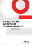
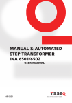
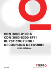
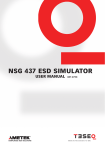
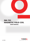
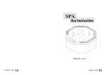
®
E stablished 1981
Advanced Test Equipment Rentals
www.atecorp.com 800-404-ATEC (2832)
1
MD 103 ESD Target Set
User Manual
601-266B
MD 103 ESD Target Set
User Manual
MD 103 ESD target set
contentS
1
Safety terms and symbols
2
The ESD target set
3
Handling of the target set
4
Requirements by a new draft standard
5
Using the target
6
Relation between voltage and real current flowing
7
Preparing the target for calibration with INA 103 adapter
8
Calibrating the target using INA 103 option
9
Determining the low frequency transfer impedance
10 Technical specifications MD 103
11 Ordering information
12Addresses
5
6
7
9
10
12
13
16
19
20
21
22
1 Safety terms and symbols
Please take note of the following explanations of the symbols used in order
to achieve the optimum benefit from this manual and to ensure safety during
operation of the equipment.
The following symbol draws your attention to a circumstance where nonobservation of the warning could lead to inconvenience or impairment in the
performance.
Example:
Caution statements identify conditions or practices
that could result in damage to this product or other property.
5
6
2 The ESD target set
An ESD target is a shunt for measuring the ESD discharge current flowing in
a measurement circuit. The target is intended to emulate a discharge into a
perfect ground plane. To minimize the error caused by any difference between
a perfect conducting plane and the input impedance of the target, a 2.1 Ω limit
has been set for the input impedance.
The impedance of the MD 103 target is 1.03 Ω. An even smaller impedance value
would generate a very small output signal which would be subject to errors due
to coupling into cables and oscilloscope.
A very important parameter of the target is the DC transfer impedance Z SYS, this
is the ratio between the voltage measured on the scope and the real current
flowing through the target. For the exact value, please refer to the calibration
certificate.
MD 103 ESD target set
3Handling of the target set
The target consists of the complete set with cable, attenuator and discharge
part (target) like the pictures below.
The MD 103 is a high precision device,
please handle with care.
Leave the ESD target with the attenuator and the cable
together and do not disassemble the set in parts, since
the whole coupling path has been calibrated in one
piece.
7
8
MD 103 parts identification:
Carry case
User manual
Calibration certificate
ESD target
Attenuator 20 dB
Coax cable Sucoflex
The carry case has extra space for the calibration adapter INA 103, the special
screw tool and an adapter to connect to an analyzer or to a scope.
MD 103 ESD target set
4Requirements by a new draft
standard
In order to improve the reproducibility between calibration laboratories, the
frequency characteristic of the target has now been defined in a new draft
standard submitted by ANSI and IEC.
The new draft of the standard sets limits for the insertion loss of the whole measurement chain including the target itself, cables and any attenuator present.
The variation in the insertion loss of the chain may not exceed:
+/- 0.3 dB up to 1 GHz
+/- 1 dB between 1 GHz and 4 GHz
The MD 103 shows an almost flat frequency response up to 4 GHz. The next
figure shows the insertion loss of the MD 103 (solid line) and the permitted
tolerances (dotted lines).
Reflection coefficent [dB]
–47
–48
–49
–50
0
1·109
Frequenzy [Hz]
2·109
3·109
4·109
4 GHz
9
5 Using the target
The MD 103 target comes fully assembled ready to be screwed into the reference plane. The plane should be at least 1.2 x 1.2 m in size and forms part of a
HF-tight enclosure for cables, attenuators and the oscilloscope.
Shielded enclosure
for the oscilloscope
and connecting
cables
1.2 m
Ground plane
ESD
simulator
Current
target
1.2 m
10
Ground strap
(pulled away
at its
midpoint)
Ground strap
connection point
Power cord
RF filter for
AC power
Typical arrangement for calibration of ESD simulator performance.
MD 103 ESD target set
This is the drilling template for the reference plane.
11
45°
Canter hole
51 + 0.5 mm
Thread M3
60 mm
Schematically, the measurement chain looks as follows.
Frequency
response of
cables, attenuator
and connectors
>>2 GHz
Oscilloscope min. 2 GHz
analogue bandwidth
12
6Relation between voltage and
real current flowing
To get the peak current, a suitable scope will be needed as well as the exact
transfer impedance ratio value Z SYS, which is found in the calibration certificate.
If the target is mounted, and the measuring setup conforms to the standard recommendations, then following calculation has to be made to get the current.
Measured peak voltage [V]
Low frequency transfer impedance ratio [Ω]
= Pulse peak current [A]
Numeric example:
Set the ESD simulator to 8 kV and discharge directly to the target so the peak
voltage on the scope in the 50 Ω system is 2.89 V. The transfer impedance for
1
the MD 103 is Z SYS = 0.098 Ω or 10.3 Ω [Siemens].
2.89 V
0.098 = 29.49 A
So the calculated peak current flow is 29.49 A by 8 kV ESD voltage. To fulfill the
IEC/EN 61000-4-2 recommendation the 30 ns and the 60 ns point needs to be
measured and calculated, too.
MD 103 ESD target set
7 Preparing the target for calibration with INA 103 adapter
The optional INA 103 is needed if the
target has to be calibrated. The INA
103 calibration adapter can be placed
in the MD 103 carry case.
For calibration, unscrew the center
contact bolt with the special screw
tool and remove it carefully.
13
14
Unscrew the INA 103 connector socket from the calibration ring. Disassemble
the INA 103 adapter to the following parts.
Connector socket
Calibration ring
The center pin of the connector socket
can be disassembled to into connector
pin, isolator and screw bolt.
Connector pin
Isolator
Screw bolt
Screw now the calibration ring onto the
target.
MD 103 ESD target set
Screw from the center pin the screw
bolt into the target, add the isolator
and screw the connector pin into the
screw bolt.
Screw the connector socket onto the
calibration ring.
The assembled target with the calibration adapter is now ready to be used for
calibration.
15
16
8Calibrating the target using
INA 103 option
According to the new draft standard, the insertion loss of the target should
be measured with a network analyzer. The network analyzer has two coaxial
connection ports. For insertion loss measurements on the target an adapter is
necessary, which provides a matched low reflection from the front side of the
target to the coaxial connector of the network analyzer.
Network analyzer
Signal
OUT
Attenuator B
Calibration
adaper
INA 103
Signal
IN
MD 103
ESD target
Attenuator C
Cable A
Attenuator A
Calibrate the network analyzer at this point
The ESD current target, attenuator A and cable A are the target-attenuatorcable chain which is calibrated using this setup. Attenuator B and C may not
be needed.
For a proper connection to an analyzer or scope an adaptor may be needed
and can be placed into the spare place of the MD 103 carry case.
MD 103 ESD target set
In order to minimize the influence of the adapter on the measurements, frequency parameters of the adapter are specified in the draft. These parameters are verified for two adapters connected face to face. They must be as
follows:
Reflection coefficient:
< -30 dB up to 1 GHz
< -20 dB between 1 GHz and 4 GHz
–15
–20
Reflection coefficent [dB]
–25
–30
–35
–40
–45
–50
–55
–60
0
1·109
2·109
3·109
4·109
4 GHz
Frequenzy [Hz]
Reflection coefficient of two adapters for the MD 103 placed face to face (solid
line) and the permitted tolerance (dotted line).
17
Insertion loss must be better than -0.3 dB up to 4 GHz.
0
Reflection coefficent [dB]
18
-0.2
0.4
0
1·109
2·109
3·109
4·109
Frequenzy [Hz]
Insertion loss of two adapters for the MD 103 placed face to face (solid line) and
the permitted tolerance (dotted line).
Moreover the characteristic impedance of the adapter must be within the limit
of 50 Ω +/- 2% (i.e. it must be between 49 and 51 Ω). The adapter is an assembly
of coaxial cylinders with a diameter for the outer cylinder D = 16 mm +/- 0.02
mm and a diameter of the inner cylinder d = 7 mm +/- 0.02 mm. The formula
for calculating the characteristic impedance is as follows:
D
Zw = 60 ∙ ln d
The calculated characteristic impedance of the adapter is therefore 49.6 Ω.
Taking into account the tolerances, this impedance is no greater than 49.35 Ω
and no less than 49.84 Ω.
Another significant element of the adapter is the professional connector type
N-7/16 (Huber Suhner). The producer of the connector guarantees 50 Ω +/-2%
characteristic impedance up to 7.5 GHz. The requirement concerning the characteristic impedance of the adapter for the MD 103 is hence fulfilled.
MD 103 ESD target set
9 Determining the low frequency
transfer impedance
The low frequency transfer impedance of a target-attenuator-cable chain is
defined as the ratio between the current injected at the front face of the target
and the voltage across a precision 50 Ω load at the output end of the cable.
The circuit diagram for measuring the low frequency transfer impedance looks
as follows:
TargetAttenuatorCable
50 Ω
A
R
SYS
The low frequency transfer impedance can be determined by:
Injecting a DC or LF current ISYS of approx. 1 A into
the front face of the target.
Measuring the voltage V 50 across the precision 50 Ω.
Calculating the transfer impedance as follows:
D50
Zw = ISYS
V
V50
19
20
10Technical specifications
MD 103
Insertion loss (S21 parameter):
Average low frequency transfer impedance:
Inner target diameter:
Impedance:
Calibration ESD pulse amplitude:
Max. ESD pulse amplitude:
Calibration adapter
reflection coefficient:
Target parts:
Cable connectors:
MD 103 ESD target set
< -48.3 dB DC to 4 GHz
ZSYS = 0.098 Ω
7 mm
1.03 Ω (SMD design)
1/2/4/8/15 kV
30 kV
< -40 dB up to 1 GHz
< -25 dB between 1 GHz and 4 GHz
Gold plated
Type N
11Ordering information
MD 103 ESD calibration target set
Including:
Carry case
User manual
Calibration certificate
ESD target
Attenuator 20 dB
Coax cable Sucoflex
Options:
INA 103
Calibration adaptor
with special screw
tool
21
Headquarters
Teseq AG
4542 Luterbach, Switzerland
T + 41 32 681 40 40
F + 41 32 681 40 48
sales @ teseq.com
www.teseq.com
Manufacturer
Teseq AG
4542 Luterbach, Switzerland
T + 41 32 681 40 40
F + 41 32 681 40 48
sales @ teseq.com
China
Teseq Company Limited
T + 86 10 8460 8080
F + 86 10 8460 8078
chinasales @ teseq.com
France
Teseq Sarl
T + 33 1 39 47 42 21
F + 33 1 39 47 40 92
francesales @ teseq.com
Germany
Teseq GmbH
T + 49 30 5659 8835
F + 49 30 5659 8834
desales @ teseq.com
Japan
Teseq K.K.
T + 81 3 5725 9460
F + 81 3 5725 9461
japansales @t eseq.com
Singapore
Teseq Pte Ltd.
T + 65 6846 2488
F + 65 6841 4282
singaporesales @ teseq.com
Switzerland
Teseq AG
T + 41 32 681 40 50
F + 41 32 681 40 48
sales @ teseq.com
Taiwan
Teseq Ltd.
T + 886 2 2917 8080
F + 886 2 2917 2626
taiwansales @ teseq.com
UK
Teseq Ltd.
T + 44 845 074 0660
F + 44 845 074 0656
uksales @ teseq.com
USA
Teseq Inc.
T + 1 732 417 0501
F + 1 732 417 0511
Toll free +1 888 417 0501
usasales @ teseq.com
© December 2010 Teseq®
Specifications subject to change
without notice. Teseq® is an ISOregistered company. Its products are
designed and manufactured under
the strict quality and environmental
requirements of the ISO 9001. This
To find your local partner within document has been carefully checked.
Teseq®’s global network, please go to However, Teseq® does not assume
www.teseq.com
any liability for errors or inaccuracies.