1
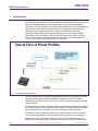
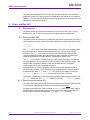
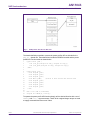
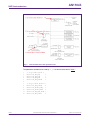
AN11043 Power profiles on the LPC1100L Rev. 1.1 — 1 March 2011 Application note Document information Info Content Keywords Power profiles API, ROM, LPC1100L, Low Current, Efficiency, Performance, set_pll, set_power, LPCXpresso Abstract This application note aims to describe how to use the LPC1100L’s power profiles and to point out what advantages they provide. AN11043 NXP Semiconductors Power profiles on the LPC1100L Revision history Rev Date 1.1 Description 20110301 Updated Fig 2 Added Fig 5 Corrected: Default mode is not required for IAP calls. 1 20110214 Initial version. Contact information For more information, please visit: http://www.nxp.com For sales office addresses, please send an email to: [email protected] AN11043 Application note All information provided in this document is subject to legal disclaimers. Rev. 1.1 — 1 March 2011 © NXP B.V. 2011. All rights reserved. 2 of 24 AN11043 NXP Semiconductors Power profiles on the LPC1100L 1. Introduction The API-driven power profiles featured in the LPC1100L provide users with ready-to-use power management templates. The power profiles can be customized for any low-power application allowing designers to reach ideal power levels with minimal application intervention. The power profiles serve as an excellent alternative to non-configurable low power modes, as they can conduct dynamic power management and optimize CPU operation for various application states. This feature minimizes overall energy consumption while maintaining the lowest operating current at low supply voltages. Optimized for CPU performance, CPU efficiency and lowest active current, the power profiles enable maximum operating frequency through the entire voltage range from 1.8 V to 3.6 V without compromising speed or functionality. 019aab688 Fig 1. Typical flow of power profiles The Low Current mode is intended for applications that focus on lowering active current, keeping the CPU's high processing capabilities available as required. CoreMark benchmarks have shown a 20 % to 30 % improvement in power consumption when this mode is enabled. In CPU Performance mode, the microcontroller is configured to increase CPU throughput by providing more processing capability to the application. CoreMark benchmark results have proven that scores increase by 35 % when compared to regular operation. The Efficiency mode is designed to deliver a fine balance between the CPU's ability to execute code, process data, and at the same time lower active current consumption. Regardless of which power mode is used (Low Current, CPU Performance or CPU Efficiency), all three power profile modes will consume less current than Default mode. AN11043 Application note All information provided in this document is subject to legal disclaimers. Rev. 1.1 — 1 March 2011 © NXP B.V. 2011. All rights reserved. 3 of 24 AN11043 NXP Semiconductors Power profiles on the LPC1100L The goal of this application note is to inform the user when and how to use the power profiles API on the LPC1100L. Moreover, this application note should only be used as a reference. The user needs to determine which power profile would be best suited for their application’s particular requirements. 2. Power profiles API 2.1 Requirements The power profiles API routines are available only on the LPC1100L (LPC111x/x02) devices. LPC1100 or LPC11C00 devices do not support the power profiles API. 2.2 Power profiles API The power profiles API routines are a simple and easy way to configure the LPC1100L’s clock frequency and power modes. The power profiles API consists of two function calls: set_pll() set_power() The set_pll API function determines and switches the LPC1100L to the optimal system PLL and system clock divider settings needed to achieve a desired system clock frequency. The set_pll API function relieves the user from having to calculate the required multiplier and divider settings needed to properly configure the system PLL; effectively simplifying the overall process in configuring the system clock. The set_power API function configures the LPC1100L’s power settings for four different execution profiles: Low Current mode, CPU Performance mode, Efficiency mode, or the Default mode. Changing the device’s power profile allows the user to target the microcontroller for his or her application of interest. This application note is accompanied by a sample code bundle available on NXP’s microcontrollers’ website. This bundle features an implementation of a simple wrapper function that calls both set_pll and set_power API routines. The wrapper is located in power_profiles.c and power_profiles.h files and can be used as a reference. The wrapper implementation code utilizes power profiles header definitions found in the power_api.h header file. The power_api.h header file is found in “..\Common\inc” directory. 2.2.1 Executing power profiles API The LPC1100L’s power profiles API functions are stored on the device’s ROM. API calls to the ROM are called through a series of pointers as illustrated in Fig 2. A pointer to the ROM Driver Table is located at 0x1FFF1FF8. Table entry number 4 within that ROM Driver Table contains a pointer to the power profiles API function table. The power profiles function table contains the set_pll and set_power functions. AN11043 Application note All information provided in this document is subject to legal disclaimers. Rev. 1.1 — 1 March 2011 © NXP B.V. 2011. All rights reserved. 4 of 24 AN11043 NXP Semiconductors Power profiles on the LPC1100L 019aab689 Fig 2. ROM pointer structure for API calls The header definitions needed to execute the power profiles API are included in the power_api.h header file. These definitions include the ROM Driver table and the power profiles API Function table as shown below. 1 2 3 4 5 6 7 8 9 10 11 12 13 14 15 16 17 18 typedef struct _PWRD { void (*set_pll)(unsigned int cmd[], unsigned int resp[]); void (*set_power)(unsigned int cmd[], unsigned int resp[]); } PWRD; typedef struct _ROM { const unsigned p_dev1; const unsigned p_dev2; const unsigned p_dev3; const PWRD * pPWRD; const unsigned p_dev5; const unsigned p_dev6; const unsigned p_dev7; const unsigned p_dev8; } ROM; //Pointer to Power Profiles API function table ROM ** rom = (ROM **) 0x1FFF1FF8; unsigned int command[4], result[2]; To operate the power profile API functions simply call the desired function with a set of command[] and result[] argument arrays. These 32-bit unsigned integer arrays are used to supply commands and return error codes. AN11043 Application note All information provided in this document is subject to legal disclaimers. Rev. 1.1 — 1 March 2011 © NXP B.V. 2011. All rights reserved. 5 of 24 AN11043 NXP Semiconductors Power profiles on the LPC1100L A sample call to the set_pll power profile function would then be performed as follows: 1 2 3 4 5 command[0] = 12000; command[1] = 16500; command[2] = CPU_FREQ_APPROX; command[3] = 0; (*rom)->pWRD->set_pll(command, result); Similarly, the set_power power profile function would be called as follows: 1 2 3 4 command[0] = 24; command[1] = PWR_CPU_EFFICIENCY; command[2] = 12; (*rom)->pWRD->set_power(command, result); With both set_pll and set_power examples the results of the power profile API call are stored in the result[] array. 2.2.2 set_pll API function The set_pll function configures the LPC1100L’s system clock. The primary advantage of using this function is to relieve the user from having to determine the necessary settings needed to configure the system PLL. Usage of this function comes with a set of requirements that must be met to ensure that the system clock is properly configured. The sample software included with this application note performs these steps within the config_pll_power() function. Before calling set_pll ensure the following (see Fig 3): 1. Route the IRC or the system oscillator to sys_pllclkin 2. Configure MAINCLKSEL to (MAINCLKSEL = 0x1) as main clock. a. Note that you must update MAINCLKSEL with the MAINCLKUEN register. 3. Set the System Clock Divider (SYSAHBCLKDIV = 0x1) to divide by 1. 1 2 3 4 5 6 7 8 9 10 AN11043 Application note /**** Required by the Power Profiles set_pll API ****/ /* Switch to the sys_pllclkin to the main clock */ LPC_SYSCON->MAINCLKSEL = 0x1; LPC_SYSCON->MAINCLKUEN = 0x0; LPC_SYSCON->MAINCLKUEN = 0x1; while ( !(LPC_SYSCON->MAINCLKUEN & 0x01) ); /* Wait until updated */ /* Specify AHBCLKDIV = 1 */ LPC_SYSCON->SYSAHBCLKDIV = 1; /**** END Required by the Power Profiles API ****/ All information provided in this document is subject to legal disclaimers. Rev. 1.1 — 1 March 2011 © NXP B.V. 2011. All rights reserved. 6 of 24 AN11043 NXP Semiconductors Power profiles on the LPC1100L 019aab690 Fig 3. LPC111x/LPC11C1x clock generation unit The parameters available to be used by set_pll are shown below and in Table 1. 1 2 3 4 5 6 7 8 9 10 11 12 AN11043 Application note /* set_pll mode options */ #define CPU_FREQ_EQU 0 #define CPU_FREQ_LTE 1 #define CPU_FREQ_GTE 2 #define CPU_FREQ_APPROX 3 /* set_pll result options */ #define PLL_CMD_SUCCESS 0 #define PLL_INVALID_FREQ 1 #define PLL_INVALID_MODE 2 #define PLL_FREQ_NOT_FOUND 3 #define PLL_NOT_LOCKED 4 All information provided in this document is subject to legal disclaimers. Rev. 1.1 — 1 March 2011 © NXP B.V. 2011. All rights reserved. 7 of 24 AN11043 NXP Semiconductors Power profiles on the LPC1100L Table 1. Routine set_pll routine set_pll Description Input command[0]: System PLL input frequency in kHz This argument tells the API function at what frequency the IRC/system oscillator is currently clocked at. command[1]: Expected system clock in kHz This argument specifies the desired system clock frequency the API should apply. command[2]: Mode (CPU_FREQ_EQU | CPU_FREQ_LTE | CPU_FREQ_GTE | CPU_FREQ_APPROX) This mode determines the desired outcome if an exact match of the clock frequency requested cannot be found. A call specifying CPU_FREQ_EQU will only succeed if the PLL can output exactly the frequency requested in command[1]. CPU_FREQ_LTE can be used if the requested frequency should not be exceeded (such as overall current consumption and/or power budget reasons). CPU_FREQ_GTE helps applications that need a minimum level of CPU processing capabilities. CPU_FREQ_APPROX results in a system clock that is as close as possible to the requested value (it may be greater than or less than the requested value). command[3]: System PLL lock timeout This parameter specifies a timeout on how many polling cycles the API function will wait until a PLL has been achieved. This assumes of course that the desired system clock frequency should require the PLL. Setting this parameter to the desired system frequency in Hz divided by 10000 should be enough time for PLL lock to take place. Result result[0]: PLL_CMD_SUCCESS | PLL_INVALID_FREQ | PLL_INVALID_MODE | PLL_FREQ_NOT_FOUND | PLL_NOT_LOCKED A call to the set_pll routine will result with a status code, indicating a successful routine call or some type of error. System clock in kHz If the set_pll function doesn’t return any errors, this return value indicates at what frequency the system clock was set to. result[1]: 2.2.3 set_power API function The set_power function configures internal power control settings to match a desired type of target application. Note that this function does NOT modify the system clock. It requires the current and new system clock arguments only to determine how long it needs to wait until the device can continue execution safely. Calling this function will allow the user to gear the LPC1100L towards four different types of execution profiles: Default mode Low Current mode Performance mode Efficiency mode Each of these profiles is designed to optimize the device towards the specified feature of interest. In any case, Low Current mode, Performance mode, and Efficiency mode will AN11043 Application note All information provided in this document is subject to legal disclaimers. Rev. 1.1 — 1 March 2011 © NXP B.V. 2011. All rights reserved. 8 of 24 AN11043 NXP Semiconductors Power profiles on the LPC1100L yield in a lower current consumption compared to using Default mode. Each particular profile power mode is described in Table 2. Table 2. Power profile modes Power profile Description Low Current mode Low Current mode is designed for applications where minimizing current consumption has higher priority than CPU execution time. Performance mode Performance mode is intended for applications where it is desired to have the fastest CPU execution; regardless of the current consumption. Efficiency mode Efficiency mode is intended as a general purpose mode where a balance between performance and low current consumption is needed. Default mode The device is in Default mode after the device performs a reset. The parameters available to be used by set_power are shown below and in Table 3. 1 2 3 4 5 6 7 8 9 10 /* set_power mode options */ #define PWR_DEFAULT 0 #define PWR_CPU_PERFORMANCE 1 #define PWR_EFFICIENCY 2 #define PWR_LOW_CURRENT 3 /* set_power result options */ #define PWR_CMD_SUCCESS 0 #define PWR_INVALID_FREQ 1 #define PWR_INVALID_MODE 2 Table 3. Routine set_power routine set_power Description Input command[0]: New system clock in MHz This argument is used to inform the API function to what system clock frequency the LPC1100L should be configured for. command[1]: Mode (PWR_DEFAULT | PWR_CPU_PERFORMANCE | PWR_EFFICIENCY | PWR_LOW_CURRENT) This mode indicates which power profile should be enabled. PWR_LOW_CURRENT is intended for those solutions that focus on lowering power consumption rather than CPU performance. PWR_CPU_PERFORMANCE configures the microcontroller so that it can provide more processing capability to the application. CPU performance is 30% better than the default option. PWR_EFFICIENCY setting was designed as a general purpose mode with a focus of providing a balance between execution time and low current consumption. PWR_DEFAULT keeps the device in a baseline power setting similar to its reset state. This mode must be used for In-Application-Programming (IAP) API routines. command[2]: Current system clock in MHz This parameter specifies the current clock rate of the LPC1100L when set_power is called. If set_pll was executed prior to calling set_power, this argument should set to the system clock frequency used before the set_pll call. AN11043 Application note All information provided in this document is subject to legal disclaimers. Rev. 1.1 — 1 March 2011 © NXP B.V. 2011. All rights reserved. 9 of 24 AN11043 NXP Semiconductors Power profiles on the LPC1100L Routine set_power Description Result result[0]: PWR_CMD_SUCCESS | PWR_INVALID_FREQ | PWR_INVALID_MODE A call to the set_power routine will result with a status code, indicating a successful routine call or some type of error. The LPC1100L user manual depicts a flow diagram on how to use the set_pll and set_power API functions in Fig 4. This diagram is useful if one would want to minimize API function calls by calling only the necessary functions required by the user application. It is important to note that a 50 µs delay is only required if set_pll is called immediately after the set_power API function call. 019aab691 Fig 4. AN11043 Application note Power profiles usage flow diagram (taken from the LPC1100L user manual) All information provided in this document is subject to legal disclaimers. Rev. 1.1 — 1 March 2011 © NXP B.V. 2011. All rights reserved. 10 of 24 AN11043 NXP Semiconductors Power profiles on the LPC1100L While Fig 4 is more detailed, another simplified alternate method can be applied. Fig 5 shows a much smaller condensed flow diagram. This version can be used for generic multi-purpose power profile function calls which handle both the set_pll and set_power. The sample project provided with this application note uses the simplified alternate method. The simplified method will always bring the LPC1100L into a default state prior to configuring the new system clock and power mode. Simplified flow: 1. Use set_power to configure the device to Default mode at 50 MHz. 2. Call set_pll to set the desired system clock frequency. 3. Again use set_power to configure the device to the desired power mode. 019aab991 Fig 5. AN11043 Application note Simplified Power Profiles usage flow diagram All information provided in this document is subject to legal disclaimers. Rev. 1.1 — 1 March 2011 © NXP B.V. 2011. All rights reserved. 11 of 24 AN11043 NXP Semiconductors Power profiles on the LPC1100L 3. Application examples This chapter describes how the program examples demonstrate the Power Profiles features. The application examples demonstrate the set_pll and set_power features separately in two different projects. Both demonstrations however utilize a UART user interface and a status LED. Current measurements however are only practical in the set_power demonstration. 3.1 Development boards The software provided along with this application note is available for the LPCXpresso and Keil µVision4 toolchains and development boards. 3.1.1 LPCXpresso The LPCXpresso development software is available at: http://lpcxpresso.code-redtech.com. To use the LPCXPresso board (Fig 6a), it is recommended to attach the Embedded Artists’ LPCXpresso Base Board (Fig 6b) to facilitate UART communications. 019aab710 019aab711 a. LPCXpresso featuring the LPC1114FBD38/302 Fig 6. b. Embedded Artists’ LPCXpresso Base Board LPCXpresso featuring the LPC1114FBD48/302 3.1.1.1 LPCXpresso UART User Interface All sample applications included in this application notes utilize the LPC1100L’s UART as a user interface (UI) to control the device’s functionality. The UART is configured for 57600-N-1. It’s recommended to use the Tera Term Pro serial terminal (with VT100 support) which is freely available. Tera Term Pro download: http://en.sourceforge.jp/projects/ttssh2/releases/ AN11043 Application note All information provided in this document is subject to legal disclaimers. Rev. 1.1 — 1 March 2011 © NXP B.V. 2011. All rights reserved. 12 of 24 AN11043 NXP Semiconductors Power profiles on the LPC1100L The LPCXpresso board itself does not include a UART to RS-232 level shifter. Therefore, it is recommended to use Embedded Artists’ LPCXpresso Base Board. This board uses a UART to USB converter to facilitate UART communications. 3.1.1.2 LPCXpresso Status LED A LED connected to PIO0_7 is used as a status indicator. It toggles every 0x10000 increments within a software counter. The LED is used in both the set_pll and set_power sample demonstrations. In the set_pll demonstration this LED gives the user a simple visual indication of the relative system clock rate chosen by the user. The higher the system clock frequency, the faster the LED will toggle. In the set_power demonstration the LED toggling indicates that the LPC1100L is in a “ready” state, waiting for a user input on the UART UI. 3.1.1.3 LPCXpresso Current Measurements The application example that demonstrates the set_power API functionality allows for current measurements by inserting an ammeter on the VDD jumper shown in Fig 6a. To measure the microcontroller’s current, remove J2 & J3 from the Embedded Artists’ LPCXpresso Base Board (Fig 6b) and use an external 3.3V power supply in series with the ammeter. The set_power software example changes the pin I/O states to minimize the current consumption where applicable. 3.1.2 Keil’s MCB1000 Keil’s µVision4 evaluation version is sufficient to compile the Power Profiles application example. Keil also provides the MCB1000 development board which is shown in Fig 7. Flashing the LPC1114/302 can be performed by using Keil’s uLink JTAG/SW debugger or Flash Magic’s free ISP programming utility. 019aab692 Fig 7. AN11043 Application note MCB1000 featuring the LPC1114FBD48/302 All information provided in this document is subject to legal disclaimers. Rev. 1.1 — 1 March 2011 © NXP B.V. 2011. All rights reserved. 13 of 24 AN11043 NXP Semiconductors Power profiles on the LPC1100L 3.1.2.1 MCB1000 UART User Interface All sample applications included in this application notes utilize the LPC1100L’s UART as a user interface (UI) to control the device’s functionality. The UART is configured for 57600-N-1. It’s recommended to use the Tera Term Pro serial terminal (with VT100 support) which is freely available. Tera Term Pro download: http://en.sourceforge.jp/projects/ttssh2/releases/ 3.1.2.2 MCB1000 Status LED An LED connected to PIO2_0 is used as a status indicator. It toggles every 0x10000 increments within a software counter. The LED is used in both the set_pll and set_power sample demonstrations. In the set_pll demonstration this LED gives the user a simple visual indication of the relative system clock rate chosen by the user. The higher the system clock frequency, the faster the LED will toggle. In the set_power demonstration the LED toggling indicates that the LPC1100L is in a “ready” state, waiting for a user input on the UART UI. 3.1.2.3 MCB1000 current measurements The application example that demonstrates the set_power API functionality allows for current measurements by inserting an ammeter on the VDD jumper (J2) shown in Fig 7. The VDD header pin located next to J3 can be used for current measurements. To measure the microcontroller’s current, it is recommended to use an external 3.3V power supply in series with the ammeter. The set_power software example changes the pin I/O states to minimize the current consumption where applicable. 3.2 Power profiles demonstrations The software provided with the application notes demonstrates the set_pll and set_power API routines separately. Selecting between the set_pll and set_power demonstrations is performed differently between LPCXpresso and Keil’s µVision. 3.2.1 LPCXPresso project selection With LPCXpresso, simply highlight the desired project demonstration and click on “Debug” as shown in Fig 8. AN11043 Application note All information provided in this document is subject to legal disclaimers. Rev. 1.1 — 1 March 2011 © NXP B.V. 2011. All rights reserved. 14 of 24 AN11043 NXP Semiconductors Power profiles on the LPC1100L 019aab719 Fig 8. Build/Debug the project demonstration 3.2.2 Keil’s µVision Project selection For µVision the demonstrations are easily selected as shown in Fig 9. 019aab693 Fig 9. Choose between the set_pll or set_power demonstration After selecting the desired target build, perform a “Rebuild” of all target files. Project Rebuild all target files AN11043 Application note All information provided in this document is subject to legal disclaimers. Rev. 1.1 — 1 March 2011 © NXP B.V. 2011. All rights reserved. 15 of 24 AN11043 NXP Semiconductors Power profiles on the LPC1100L 3.2.3 set_pll demonstration The set_pll power profiles API demonstration is designed to simply show how easy it is to configure the LPC1100L’s system clock by calling the API routines. Changes in the system clock frequency can be observed through the UART UI and the status LED toggle rate. 3.2.4 set_power demonstration The set_power Profile Profiles API demonstration serves to demonstrate several features: Easy usage Reduced current consumption Improved CPU performance To demonstrate the reduced current consumption and improved performance, this sample application repeatedly calls a constant runtime divide routine from a static library. While the LPC1100L is performing 5000000 calls to the division library, the device’s current consumption can be measured externally with an ammeter. Moreover, by using the 32-bit Timer 0, we can also measure how long it takes for these 5000000 division operations to be completed, providing a performance metric. By capturing the current consumption and time duration of 5000000 divisions, we can compare these metrics while the device is in Low Current, Efficiency, and CPU Performance mode to the Default mode. Table 4 simply summarizes what type of typical results can be expected when comparing the Low Current mode vs. Default mode, Efficiency mode vs. Default mode, and Performance mode vs. Default mode. Table 4. set_power power profile comparisons to Default mode Calling 5000000 library division calls Profile Comparison vs. Default Mode Current Consumption Execution Time Low Current mode Efficiency mode Reduced 1 Performance mode Increased Reduced Equal or Increased Reduced Reduced Results of the set_power demonstration can be seen in the 3.4.1 Sample current consumption and performance results. 3.2.5 Configuration options in set_pll and set_power examples The following options will allow for flexible project configurations. 1 2 3 4 /* Configuration options #define UART_BAUD #define ENABLE_CLKOUT #define MAIN_OSC */ 57600 0 1 “UART_BAUD” defines the baud rate for the UART UI. “ENABLE_CLKOUT” will enable or disable the clock signal of the main clock onto the CLKOUT pin (PIO0_1). To keep current consumption to a minimum, this should be kept ‘0’. “MAIN_OSC” allows the user to select between the main oscillator and the IRC oscillator as the clock source to sys_pllclkin. See Fig 3. 1. AN11043 Application note The Execution time results depend on the system clock frequency as shown in Fig 13. All information provided in this document is subject to legal disclaimers. Rev. 1.1 — 1 March 2011 © NXP B.V. 2011. All rights reserved. 16 of 24 AN11043 NXP Semiconductors Power profiles on the LPC1100L 3.3 set_pll application example The set_pll application example simply presents the user a UART UI to select a desired system clock frequency from the presented list shown in Fig 10. 019aab694 Fig 10. set_pll project menu By selecting any one of the displayed menu items (‘0’ – ‘d’) the LPC1100L will call the set_pll API function to change to the selected system clock frequency and then reconfigure the UART for the appropriate baud-rate dividers. “Selected freq:” displays the frequency option that was selected from the menu. “Newly configured freq:” displays the actual frequency output generated from set_pll. Note that set_pll has been coded to use the CPU_FREQ_APPROX parameter. 3.4 set_power application example The set_power application example also presents a UART UI to the user. Here however, the user only has the option to choose which set_power power profile test is to be executed. Fig 11 shows a sample screen after the user has made several power profile selections. A power profile test will: 1. Configure the LPC1100L to the selected power mode. 2. Disable the UART Interrupt routine to prevent unwanted interrupts during the test. 3. Put all the I/Os into a low current consumption state for the MCB1000. 4. Start the 32-bit Timer 0. 5. Execute 5000000 divisions using the division library. Before the 5000000 divisions complete, capture the current consumption from the ammeter. 6. Stop Timer 0 after 5000000 divisions. 7. Enable the I/Os for normal operation. AN11043 Application note All information provided in this document is subject to legal disclaimers. Rev. 1.1 — 1 March 2011 © NXP B.V. 2011. All rights reserved. 17 of 24 AN11043 NXP Semiconductors Power profiles on the LPC1100L 8. Enable the UART Interrupt routine for proper UART operations. 9. Display the timing results (in µs) for 5000000 divisions. To keep this project design simple, the system frequency can only be change during compile time in the main-set_power.c file. The system clock frequency is determined by the SYS_FREQ preprocessor definition. Simply choose one of the commented FREQ definitions to select the system frequency. 1 2 3 4 5 6 7 #define FREQ //#define FREQ //#define FREQ //#define FREQ //#define FREQ 50000000UL 36000000UL 30000000UL 12000000UL 6000000UL #define SYS_FREQ FREQ 019aab695 Fig 11. set_power Project Menu AN11043 Application note All information provided in this document is subject to legal disclaimers. Rev. 1.1 — 1 March 2011 © NXP B.V. 2011. All rights reserved. 18 of 24 AN11043 NXP Semiconductors Power profiles on the LPC1100L 3.4.1 Sample current consumption and performance results 5000000 Divisions: Current consumption (mA) vs Freq (MHz) Default Low Current Efficiency Performance 14 12 Current (mA) 10 8 6 4 2 0 0 5 10 15 20 25 30 35 40 45 50 Freq (MHz) (1) The result depicted in this chart applies to 5000000 “division” function calls from a sample library. (2) Results will vary depending on the application. (3) Clock source: system oscillator (4) No code optimization. Fig 12. Sample results of using set_power to reduce current consumption AN11043 Application note All information provided in this document is subject to legal disclaimers. Rev. 1.1 — 1 March 2011 © NXP B.V. 2011. All rights reserved. 19 of 24 AN11043 NXP Semiconductors Power profiles on the LPC1100L 5000000 Divisions: Process duration (us) vs Freq (MHz) Defaut Low Current Efficiency Performance 160000000 140000000 120000000 Time (us) 100000000 80000000 60000000 40000000 20000000 0 0 5 10 15 20 25 30 35 40 45 50 Freq (MHz) (1) The result depicted in this chart applies to 5000000 “division” function calls from a sample library. (5) Results will vary depending on the application. (6) Clock source: system oscillator (7) No code optimization. Fig 13. Sample Results of using set_power to improve performance 4. Conclusion The power profiles allows the user to easily change the system clock frequency dynamically without having overhead to configure the system PLL, if even necessary. It also provides a mechanism to optimize the LPC1100L for maximum current savings, maximum CPU performance, or an optimal balance of the two. Low Current mode is designed to achieve the lowest current consumption, whereas Performance mode is geared toward the shortest execution time. Efficiency mode is intended for general purpose applications where a balance between current consumption and execution time is desired. In any case, all three of these modes will require less current than Default mode. AN11043 Application note All information provided in this document is subject to legal disclaimers. Rev. 1.1 — 1 March 2011 © NXP B.V. 2011. All rights reserved. 20 of 24 AN11043 NXP Semiconductors Power profiles on the LPC1100L 5. Legal information application and use of customer’s third party customer(s). Customers should provide appropriate design and operating safeguards to minimize the risks associated with their applications and products. 5.1 Definitions Draft — The document is a draft version only. The content is still under internal review and subject to formal approval, which may result in modifications or additions. NXP Semiconductors does not give any representations or warranties as to the accuracy or completeness of information included herein and shall have no liability for the consequences of use of such information. 5.2 Disclaimers Limited warranty and liability — Information in this document is believed to be accurate and reliable. However, NXP Semiconductors does not give any representations or warranties, expressed or implied, as to the accuracy or completeness of such information and shall have no liability for the consequences of use of such information. In no event shall NXP Semiconductors be liable for any indirect, incidental, punitive, special or consequential damages (including - without limitation lost profits, lost savings, business interruption, costs related to the removal or replacement of any products or rework charges) whether or not such damages are based on tort (including negligence), warranty, breach of contract or any other legal theory. Notwithstanding any damages that customer might incur for any reason whatsoever, NXP Semiconductors’ aggregate and cumulative liability towards customer for the products described herein shall be limited in accordance with the Terms and conditions of commercial sale of NXP Semiconductors. Right to make changes — NXP Semiconductors reserves the right to make changes to information published in this document, including without limitation specifications and product descriptions, at any time and without notice. This document supersedes and replaces all information supplied prior to the publication hereof. Suitability for use — NXP Semiconductors products are not designed, authorized or warranted to be suitable for use in life support, life-critical or safety-critical systems or equipment, nor in applications where failure or malfunction of an NXP Semiconductors product can reasonably be expected to result in personal injury, death or severe property or environmental damage. NXP Semiconductors accepts no liability for inclusion and/or use of NXP Semiconductors products in such equipment or applications and therefore such inclusion and/or use is at the customer’s own risk. Applications — Applications that are described herein for any of these products are for illustrative purposes only. NXP Semiconductors makes no representation or warranty that such applications will be suitable for the specified use without further testing or modification. NXP Semiconductors does not accept any liability related to any default, damage, costs or problem which is based on any weakness or default in the customer’s applications or products, or the application or use by customer’s third party customer(s). Customer is responsible for doing all necessary testing for the customer’s applications and products using NXP Semiconductors products in order to avoid a default of the applications and the products or of the application or use by customer’s third party customer(s). NXP does not accept any liability in this respect. Export control — This document as well as the item(s) described herein may be subject to export control regulations. Export might require a prior authorization from national authorities. Evaluation products — This product is provided on an “as is” and “with all faults” basis for evaluation purposes only. NXP Semiconductors, its affiliates and their suppliers expressly disclaim all warranties, whether express, implied or statutory, including but not limited to the implied warranties of noninfringement, merchantability and fitness for a particular purpose. The entire risk as to the quality, or arising out of the use or performance, of this product remains with customer. In no event shall NXP Semiconductors, its affiliates or their suppliers be liable to customer for any special, indirect, consequential, punitive or incidental damages (including without limitation damages for loss of business, business interruption, loss of use, loss of data or information, and the like) arising out the use of or inability to use the product, whether or not based on tort (including negligence), strict liability, breach of contract, breach of warranty or any other theory, even if advised of the possibility of such damages. Notwithstanding any damages that customer might incur for any reason whatsoever (including without limitation, all damages referenced above and all direct or general damages), the entire liability of NXP Semiconductors, its affiliates and their suppliers and customer’s exclusive remedy for all of the foregoing shall be limited to actual damages incurred by customer based on reasonable reliance up to the greater of the amount actually paid by customer for the product or five dollars (US$5.00). The foregoing limitations, exclusions and disclaimers shall apply to the maximum extent permitted by applicable law, even if any remedy fails of its essential purpose. 5.3 Trademarks Notice: All referenced brands, product names, service names and trademarks are property of their respective owners. Customers are responsible for the design and operation of their applications and products using NXP Semiconductors products, and NXP Semiconductors accepts no liability for any assistance with applications or customer product design. It is customer’s sole responsibility to determine whether the NXP Semiconductors product is suitable and fit for the customer’s applications and products planned, as well as for the planned AN11043 Application note All information provided in this document is subject to legal disclaimers. Rev. 1.1 — 1 March 2011 © NXP B.V. 2011. All rights reserved. 21 of 24 AN11043 NXP Semiconductors Power profiles on the LPC1100L 6. List of figures Fig 1. Fig 2. Fig 3. Fig 4. Fig 5. Fig 6. Fig 7. Fig 8. Fig 9. Fig 10. Fig 11. Fig 12. Fig 13. Typical flow of power profiles ............................3 ROM pointer structure for API calls...................5 LPC111x/LPC11C1x clock generation unit .......7 Power profiles usage flow diagram (taken from the LPC1100L user manual) ...........................10 Simplified Power Profiles usage flow diagram 11 LPCXpresso featuring the LPC1114FBD48/302 ........................................................................12 MCB1000 featuring the LPC1114FBD48/302 .13 Build/Debug the project demonstration ...........15 Choose between the set_pll or set_power demonstration .................................................15 set_pll project menu ........................................17 set_power Project Menu .................................18 Sample results of using set_power to reduce current consumption .......................................19 Sample Results of using set_power to improve performance....................................................20 AN11043 Application note All information provided in this document is subject to legal disclaimers. Rev. 1.1 — 1 March 2011 © NXP B.V. 2011. All rights reserved. 22 of 24 AN11043 NXP Semiconductors Power profiles on the LPC1100L 7. List of tables Table 1. Table 2. Table 3. Table 4. set_pll routine....................................................8 Power profile modes .........................................9 set_power routine .............................................9 set_power power profile comparisons to Default mode ...............................................................16 AN11043 Application note All information provided in this document is subject to legal disclaimers. Rev. 1.1 — 1 March 2011 © NXP B.V. 2011. All rights reserved. 23 of 24 AN11043 NXP Semiconductors Power profiles on the LPC1100L 8. Contents 1. Introduction .........................................................3 2. Power profiles API...............................................4 2.1 Requirements.....................................................4 2.2 Power profiles API..............................................4 2.2.1 Executing power profiles API .............................4 2.2.2 set_pll API function ............................................6 2.2.3 set_power API function ......................................8 3. Application examples .......................................12 3.1 Development boards ........................................12 3.1.1 LPCXpresso .....................................................12 3.1.1.1 LPCXpresso UART User Interface...................12 3.1.1.2 LPCXpresso Status LED ..................................13 3.1.1.3 LPCXpresso Current Measurements ...............13 3.1.2 Keil’s MCB1000................................................13 3.1.2.1 MCB1000 UART User Interface .......................14 3.1.2.2 MCB1000 Status LED ......................................14 3.1.2.3 MCB1000 current measurements ....................14 3.2 Power profiles demonstrations .........................14 3.2.1 LPCXPresso project selection..........................14 3.2.2 Keil’s µVision Project selection.........................15 3.2.3 set_pll demonstration .......................................16 3.2.4 set_power demonstration .................................16 3.2.5 Configuration options in set_pll and set_power examples..........................................................16 3.3 set_pll application example ..............................17 3.4 set_power application example ........................17 3.4.1 Sample current consumption and performance results ..............................................................19 4. Conclusion.........................................................20 5. Legal information ..............................................21 5.1 Definitions ........................................................21 5.2 Disclaimers.......................................................21 5.3 Trademarks ......................................................21 6. List of figures.....................................................22 7. List of tables ......................................................23 8. Contents.............................................................24 Please be aware that important notices concerning this document and the product(s) described herein, have been included in the section 'Legal information'. © NXP B.V. 2011. All rights reserved. For more information, please visit: http://www.nxp.com For sales office addresses, please send an email to: [email protected] Date of release: 1 March 2011 Document identifier: AN11043