1
PV Inverter
SUNNY BOY 2000HF‑US/2500HF‑US/3000HF‑US
Installation Guide
SB20_25_30HFUS-eng-IUS113711 | IMUS-SB20-30HFUS | Version 1.1
CA
US
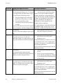
Please contact SMA.
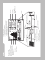
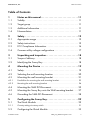
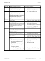
Device fault
Failure that can be removed on-site (see chapter 10.3 )
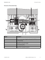
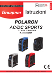
Power curve or energy
curve of the past 16 feedin hours or past 16 days (switching the display is done by knocking on the lid)
• Sunny Boy might need better ventilation
• Clean the fan (if necessary)
Power reduction due to excessive temperature
PV array event number Input voltage / input current
Grid event number
Output voltage / output current
Sunny Boy event number
Grid relay
Bluetooth connection to other Sunny Boys
• Switching through the line display
• Switching through the power values of the past 16 feedin hours to the daily power values of the past 16 days
• Activating the background illumination
Knocking on the upper lid:
Event text
Total energy fed
in since the Sunny Boy was installed
Daily energy
Actual output
SMA America, LLC
Legal Restrictions
Copyright © 2011 SMA America, LLC. All rights reserved.
No part of this document may be reproduced, stored in a retrieval system, or transmitted, in any form
or by any means, electronic, mechanical, photographic, magnetic or otherwise, without the prior
written permission of SMA America, LLC.
Neither SMA America, LLC nor SMA Solar Technology Canada Inc. makes representations, express
or implied, with respect to this documentation or any of the equipment and/or software it may
describe, including (with no limitation) any implied warranties of utility, merchantability, or fitness for
any particular purpose. All such warranties are expressly disclaimed. Neither SMA America, LLC nor
its distributors or dealers nor SMA Solar Technology Canada Inc. nor its distributors or dealers shall
be liable for any indirect, incidental, or consequential damages under any circumstances.
The exclusion of implied warranties may not apply in all cases under some statutes, and thus the
above exclusion may not apply.
Specifications are subject to change without notice. Every attempt has been made to make this
document complete, accurate and up-to-date. Readers are cautioned, however, that
SMA America, LLC and SMA Solar Technology Canada Inc. reserve the right to make changes
without notice and shall not be responsible for any damages, including indirect, incidental or
consequential damages, caused by reliance on the material presented, including, but not limited to,
omissions, typographical errors, arithmetical errors or listing errors in the content material.
All trademarks are recognized even if these are not marked separately. Missing designations do not
mean that a product or brand is not a registered trademark.
The Bluetooth® word mark and logos are registered trademarks owned by Bluetooth SIG, Inc. and
any use of such marks by SMA America, LLC and SMA Solar Technology Canada Inc. is under
license.
SMA America, LLC
3801 N. Havana Street
Denver, CO 80239 U.S.A.
SMA Solar Technology Canada Inc.
2425 Matheson Blvd. E, 8th Floor
Mississauga, ON L4W 5K5, Canada
Installation Guide
SB20_25_30HFUS-eng-IUS113711
3
Important Safety Instructions
SMA America, LLC
IMPORTANT SAFETY INSTRUCTIONS
SAVE THESE INSTRUCTIONS
This manual contains important instructions for models Sunny Boy 2000HF‑US, 2500HF‑US, 3000HF‑US inverter, that must be followed during installation and maintenance of the inverter.
The Sunny Boy is designed and tested according to international safety requirements, but as with all
electrical and electronic equipment, certain precautions must be observed when installing and/
or operating the Sunny Boy. To reduce the risk of personal injury and to ensure the safe installation and operation of the Sunny Boy, you must carefully read and follow all instructions, cautions and
warnings in this installation manual.
Warnings in this document
A warning describes a hazard to equipment or personnel. It calls attention to a procedure or practice,
which, if not correctly performed or adhered to, could result in damage to or destruction of part or all
of the SMA equipment and/or other equipment connected to the SMA equipment or personal injury.
DANGER
DANGER indicates a hazardous situation which, if not avoided, will result in death or
serious injury.
WARNING
WARNING indicates a hazardous situation which, if not avoided, could result in death or
serious injury.
CAUTION
CAUTION indicates a hazardous situation which, if not avoided, could result in minor or
moderate injury.
NOTICE
NOTICE is used to address practices not related to personal injury.
4
SB20_25_30HFUS-eng-IUS113711
Installation Guide
SMA America, LLC
Important Safety Instructions
Other symbols in this document
In addition to the safety and hazard symbols described on the previous pages, the following symbol
is also used in this installation guide:
Information
This symbol accompanies notes that call attention to supplementary information that you
must know and use to ensure optimal operation of the system.
Markings on this product
The following symbols are used as product markings with the following meanings.
Warning regarding dangerous voltage
The product works with high voltages. All work on the product must only be performed
as described in the documentation of the product.
Beware of hot surface
The product can become hot during operation. Do not touch the product during
operation.
Observe the operating instructions
Read the documentation of the product before working on it. Follow all safety
precautions and instructions as described in the documentation.
This inverter is evaluated to UL 1741, which includes assessment to all of the
requirements of IEEE1547 and IEEE1547.1, which are an outgrowth and further
development of the IEEE recommended practices and guidelines contained in IEEE Std.
929-2000. IEEE 929-2000 provides recommendations regarding the proper equipment
and functionality necessary to ensure compatible operation when power generation is
connected to the utility grid. The inverter is additionally evaluated to CAN/CSA C22.2
No. 107.1-1.
Installation Guide
SB20_25_30HFUS-eng-IUS113711
5
General Warnings
SMA America, LLC
General Warnings
General Warnings
All electrical installations must be done in accordance with the local and
National Electrical Code® ANSI/NFPA 70 or the Canadian Electrical Code®
CSA C22.1. This document does not and is not intended to replace any local, state,
provincial, federal or national laws, regulation or codes applicable to the installation and
use of the inverter, including without limitation applicable electrical safety codes. All
installations must conform with the laws, regulations, codes and standards applicable in
the jurisdiction of installation. SMA assumes no responsibility for the compliance or
noncompliance with such laws or codes in connection with the installation of the inverter.
The Sunny Boy contains no user-serviceable parts except for the fan on the bottom of the
enclosure. For all repair and maintenance always return the unit to an authorized SMA
Service Center.
Before installing or using the Sunny Boy, read all of the instructions, cautions, and warnings
on the Sunny Boy in this installation guide.
Before connecting the Sunny Boy to the power distribution grid, contact the local power
distribution grid company. This connection must be made only by qualified personnel.
6
SB20_25_30HFUS-eng-IUS113711
Installation Guide
SMA America, LLC
Table of Contents
Table of Contents
1
1.1
1.2
1.3
1.4
Notes on this manual. . . . . . . . . . . . . . . . . . . . . . . . . . . . . 11
Validity . . . . . . . . . . . . . . . . . . . . . . . . . . . . . . . . . . . . . . . . . . . 11
Target group . . . . . . . . . . . . . . . . . . . . . . . . . . . . . . . . . . . . . . . 11
Additional information . . . . . . . . . . . . . . . . . . . . . . . . . . . . . . . 11
Nomenclature . . . . . . . . . . . . . . . . . . . . . . . . . . . . . . . . . . . . . . 11
2
2.1
2.2
2.3
2.4
Safety . . . . . . . . . . . . . . . . . . . . . . . . . . . . . . . . . . . . . . . . . 12
Appropriate usage . . . . . . . . . . . . . . . . . . . . . . . . . . . . . . . . . . 12
Safety instructions . . . . . . . . . . . . . . . . . . . . . . . . . . . . . . . . . . . 15
FCC Compliance Information . . . . . . . . . . . . . . . . . . . . . . . . . . 16
Common utility voltage configurations . . . . . . . . . . . . . . . . . . . 17
3
3.1
3.2
Unpacking and inspection. . . . . . . . . . . . . . . . . . . . . . . . . 18
Scope of delivery . . . . . . . . . . . . . . . . . . . . . . . . . . . . . . . . . . . 18
Identifying the Sunny Boy . . . . . . . . . . . . . . . . . . . . . . . . . . . . . 18
4
4.1
4.2
4.3
Mounting the Device . . . . . . . . . . . . . . . . . . . . . . . . . . . . . 19
Safety . . . . . . . . . . . . . . . . . . . . . . . . . . . . . . . . . . . . . . . . . . . . 19
Selecting the wall mounting location . . . . . . . . . . . . . . . . . . . . 20
Mounting the wall mounting bracket . . . . . . . . . . . . . . . . . . . . 21
4.3.1
Possibilities for mounting the wall mounting bracket . . . . . . . . . . . . . . . . . . . 23
4.3.2
Mounting the wall mounting bracket. . . . . . . . . . . . . . . . . . . . . . . . . . . . . . . 24
4.4
4.5
4.6
Mounting the SMA DC-Disconnect. . . . . . . . . . . . . . . . . . . . . . 25
Mounting the Sunny Boy onto the Wall mounting bracket . . . . 27
Grounding the SMA DC-Disconnect . . . . . . . . . . . . . . . . . . . . . 28
5
5.1
Configuring the Sunny Boy . . . . . . . . . . . . . . . . . . . . . . . . 29
The Quick Module . . . . . . . . . . . . . . . . . . . . . . . . . . . . . . . . . . 29
5.1.1
Country setting via rotary switch . . . . . . . . . . . . . . . . . . . . . . . . . . . . . . . . . . 31
5.2
Configuring the Quick Module . . . . . . . . . . . . . . . . . . . . . . . . . 33
Installation Guide
SB20_25_30HFUS-eng-IUS113711
7
Table of Contents
SMA America, LLC
5.2.1
Configuration before installation. . . . . . . . . . . . . . . . . . . . . . . . . . . . . . . . . . 33
5.2.2
Configuration for Bluetooth communication . . . . . . . . . . . . . . . . . . . . . . . . . 34
5.2.3
Closing the Quick Module . . . . . . . . . . . . . . . . . . . . . . . . . . . . . . . . . . . . . . 35
5.3
5.4
Mounting the Quick Module . . . . . . . . . . . . . . . . . . . . . . . . . . 35
Configuration after installation . . . . . . . . . . . . . . . . . . . . . . . . . 37
5.4.1
Opening the installed Quick Module . . . . . . . . . . . . . . . . . . . . . . . . . . . . . . 37
5.5
Disassembling the Quick Module . . . . . . . . . . . . . . . . . . . . . . . 39
6
6.1
6.2
6.3
Wiring the Sunny Boy . . . . . . . . . . . . . . . . . . . . . . . . . . . . 40
Safety . . . . . . . . . . . . . . . . . . . . . . . . . . . . . . . . . . . . . . . . . . . . 40
Lower view of the SMA DC-Disconnect . . . . . . . . . . . . . . . . . . 42
Connection of the PV array (DC) . . . . . . . . . . . . . . . . . . . . . . . 43
6.3.1
Installing cable conduits and leading cable into the Sunny Boy. . . . . . . . . . 44
6.4
6.5
6.6
Connection of PV strings without optional string fuses . . . . . . . 46
Connection of PV strings with optional fuses. . . . . . . . . . . . . . . 50
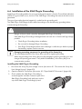
Installation of the SMA Plug-in Grounding . . . . . . . . . . . . . . . . 54
6.6.1
Configurable Grounding Parameters . . . . . . . . . . . . . . . . . . . . . . . . . . . . . . 56
6.6.2
Parameter "Module grounding prescribed?" or "GndMdt". . . . . . . . . . . . . . 56
6.6.3
Error Messages . . . . . . . . . . . . . . . . . . . . . . . . . . . . . . . . . . . . . . . . . . . . . . . 57
6.6.4
Parameter "Prescribed grounding type" or "Md.GndModReq" . . . . . . . . . . 58
6.7
Wiring the AC Output. . . . . . . . . . . . . . . . . . . . . . . . . . . . . . . . 59
6.7.1
AC connection safety requirements. . . . . . . . . . . . . . . . . . . . . . . . . . . . . . . . 59
6.7.2
Connecting the Sunny Boy on the AC side . . . . . . . . . . . . . . . . . . . . . . . . . . 60
6.8
Closing the SMA DC Disconnect . . . . . . . . . . . . . . . . . . . . . . . 62
7
Commissioning . . . . . . . . . . . . . . . . . . . . . . . . . . . . . . . . . . 63
8
8.1
8.2
8.3
Opening and closing . . . . . . . . . . . . . . . . . . . . . . . . . . . . . 65
Disconnect the Sunny Boy from Voltage Sources . . . . . . . . . . . 65
Open SMA DC Disconnect. . . . . . . . . . . . . . . . . . . . . . . . . . . . 66
Closing the SMA DC-Disconnect . . . . . . . . . . . . . . . . . . . . . . . 67
8
SB20_25_30HFUS-eng-IUS113711
Installation Guide
SMA America, LLC
Table of Contents
8.4
Lock-Off function . . . . . . . . . . . . . . . . . . . . . . . . . . . . . . . . . . . . 68
8.4.1
Secure Sunny Boy against reconnection. . . . . . . . . . . . . . . . . . . . . . . . . . . . 68
8.4.2
Unlocking and switching on the Sunny Boy . . . . . . . . . . . . . . . . . . . . . . . . . 69
9
9.1
Maintenance and cleaning . . . . . . . . . . . . . . . . . . . . . . . . 70
Checking Heat Dissipation . . . . . . . . . . . . . . . . . . . . . . . . . . . . 70
9.1.1
Cleaning the fan . . . . . . . . . . . . . . . . . . . . . . . . . . . . . . . . . . . . . . . . . . . . . . 71
9.1.2
Checking the Fan . . . . . . . . . . . . . . . . . . . . . . . . . . . . . . . . . . . . . . . . . . . . . 73
9.2
9.3
Checking the SMA DC Disconnect . . . . . . . . . . . . . . . . . . . . . . 74
Exchanging fuses . . . . . . . . . . . . . . . . . . . . . . . . . . . . . . . . . . . 74
9.3.1
Exchanging SMA Plug-in Grounding fuse. . . . . . . . . . . . . . . . . . . . . . . . . . . 74
9.3.2
Replacing optional string fuses . . . . . . . . . . . . . . . . . . . . . . . . . . . . . . . . . . . 77
9.4
Inspecting and changing the varistors . . . . . . . . . . . . . . . . . . . 80
10
10.1
10.2
10.3
Messages . . . . . . . . . . . . . . . . . . . . . . . . . . . . . . . . . . . . . . 82
Green LED is lit or flashes . . . . . . . . . . . . . . . . . . . . . . . . . . . . . 82
Update Messages. . . . . . . . . . . . . . . . . . . . . . . . . . . . . . . . . . . 82
Error Messages. . . . . . . . . . . . . . . . . . . . . . . . . . . . . . . . . . . . . 83
11
11.1
11.2
11.3
11.4
11.5
Troubleshooting . . . . . . . . . . . . . . . . . . . . . . . . . . . . . . . . . 88
Checking the PV array for Ground Fault. . . . . . . . . . . . . . . . . . 88
Correct Grounding Fuse Fault. . . . . . . . . . . . . . . . . . . . . . . . . . 89
Correct the Grounding Type. . . . . . . . . . . . . . . . . . . . . . . . . . . 90
Exchanging Grounding Fuse . . . . . . . . . . . . . . . . . . . . . . . . . . 91
AC fault. . . . . . . . . . . . . . . . . . . . . . . . . . . . . . . . . . . . . . . . . . . 91
12
12.1
12.2
12.3
12.4
12.5
Decommissioning . . . . . . . . . . . . . . . . . . . . . . . . . . . . . . . . 92
Disassembling the Sunny Boy . . . . . . . . . . . . . . . . . . . . . . . . . . 92
Disassembling SMA DC-Disconnect . . . . . . . . . . . . . . . . . . . . . 95
Disassemble the Sunny Boy for Transport. . . . . . . . . . . . . . . . 100
Packaging the Sunny Boy . . . . . . . . . . . . . . . . . . . . . . . . . . . . 100
Storing the Sunny Boy. . . . . . . . . . . . . . . . . . . . . . . . . . . . . . . 100
Installation Guide
SB20_25_30HFUS-eng-IUS113711
9
Table of Contents
SMA America, LLC
12.6
12.7
Disposing of the Sunny Boy . . . . . . . . . . . . . . . . . . . . . . . . . . 100
Supplementary Information. . . . . . . . . . . . . . . . . . . . . . . . . . . 100
12.7.1
Connect wires to DC terminal block . . . . . . . . . . . . . . . . . . . . . . . . . . . . . . 100
12.7.2
Disconnect wires from DC terminal block . . . . . . . . . . . . . . . . . . . . . . . . . . 101
12.7.3
Disconnect wires from AC-terminal block . . . . . . . . . . . . . . . . . . . . . . . . . . 102
13
13.1
13.2
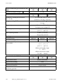
Technical Data . . . . . . . . . . . . . . . . . . . . . . . . . . . . . . . . . 103
Torque Values and Wire Sizes . . . . . . . . . . . . . . . . . . . . . . . . 105
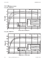
Efficiency curves . . . . . . . . . . . . . . . . . . . . . . . . . . . . . . . . . . . 106
14
Accessories . . . . . . . . . . . . . . . . . . . . . . . . . . . . . . . . . . . . 108
15
Contact . . . . . . . . . . . . . . . . . . . . . . . . . . . . . . . . . . . . . . . 109
10
SB20_25_30HFUS-eng-IUS113711
Installation Guide
SMA America, LLC
Notes on this manual
1 Notes on this manual
This manual describes the assembly, installation, commissioning and maintenance of the following
SMA inverters:
• Sunny Boy 2000HF‑US (SB 2000HFUS-30)
• Sunny Boy 2500HF‑US (SB 2500HFUS-30)
• Sunny Boy 3000HF‑US (SB 3000HFUS-30)
This manual does not cover any details concerning equipment connected to the Sunny Boy (e. g. solar
modules). Information concerning the connected equipment is available from the manufacturer of the
equipment.
1.1 Validity
This manual is valid for the Sunny Boy 2000HF‑US, Sunny Boy 2500HF‑US and
Sunny Boy 3000HF‑US.
1.2 Target group
This manual is for qualified personnel. Qualified personnel have received training and have
demonstrated skills and knowledge in the construction and operation of the device. Qualified
personnel is trained to deal with the dangers and hazards involved in installing electric devices.
WARNING
Dangerous voltages are present at various points in a PV system. For safety reasons, it is
recommended that only qualified personnel install and operate this equipment.
1.3 Additional information
You can find further information on special subjects in the download area of www.SMA‑America.com.
Refer to the user manual for detailed information on operating the Sunny Boy.
1.4 Nomenclature
In this document SMA America Production, LLC and SMA Solar Technology Canada Inc. are referred
to in the following as SMA.
Installation Guide
SB20_25_30HFUS-eng-IUS113711
11
Safety
SMA America, LLC
2 Safety
2.1 Appropriate usage
The Sunny Boy is a PV inverter which converts the direct current of a PV array into alternating current
and feeds this into the power distribution grid. The Sunny Boy is suitable for installation indoors and
outdoors.
You can use the generated alternating current electricity as follows:
House grid:
The energy is fed into the house grid and is used there by connected
consumers (for example household devices or lights). The surplus energy is
fed into the power distribution grid. When the Sunny Boy is not generating
energy, for example at night, the connected consumers are supplied by the
power distribution grid.
The Sunny Boy does not have its own energy meter. When the energy is
supplied into the power distribution grid, the energy meter runs in reverse.
Power distribution grid: The energy is fed directly into the power distribution grid. The Sunny Boy
does not have its own energy meter. Dependent on the utility supplier, the
energy produced is compensated.
Stand-alone grid:
The Sunny Boy is connected to a stand-alone grid. A stand-alone grid is a
grid which is not connected to a power distribution grid. The Sunny Boy
requires a grid forming device, for example a Sunny Island, for operation.
The energy generated is consumed directly on site. Surplus energy can be
stored in batteries using proper equipment.
AC and DC load circuit breaker
Secure the AC and DC cables on the Sunny Boy with load circuit breakers. With the AC and DC load
circuit breakers you can safely disconnect the Sunny Boy from the grid and the PV arrays. A DC load
circuit breaker is included in the Sunny Boy delivery. You must provide an AC load circuit breaker.
12
SB20_25_30HFUS-eng-IUS113711
Installation Guide
SMA America, LLC
Safety
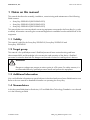
Principle of a PV plant with this Sunny Boy
Position
A
B
C
D
E
F
Name
PV array
Sunny Boy with integrated SMA DC-Disconnect
Line circuit breaker
Load
Energy meter
Power distribution grid
You must operate the Sunny Boy only with PV arrays (modules and cabling) of protection class II.
Do not connect any sources of energy other than PV modules to the Sunny Boy.
When designing the PV system, ensure that the values comply with the permitted operating range of
all components at all times. The free design program ”Sunny Design” (www.SMA‑America.com) will
assist you. The manufacturer of the PV modules must have approved the modules for use with this
Sunny Boy device. You must also ensure that all measures recommended by the module manufacturer
for long-term maintenance of the module properties are taken. You will find further information in the
download area of www.SMA‑America.com.
Do not use the Sunny Boy for purposes other than those described here. Alternative uses,
modifications to the Sunny Boy or the installation of components not expressly recommended or sold
by the manufacturer void the warranty claims and operation permission.
Anti-Islanding protection
Islanding is a condition that can occur if the power distribution grid is disconnected while the
Sunny Boy is operating and the remaining load is resonant at 60 Hz and matches the output of the
Sunny Boy perfectly. This condition is highly unlikely and had never been witnessed outside of a
controlled laboratory. Nevertheless, the Sunny Boy incorporates an advanced active islanding
protection algorithm to ensure that the system will not export power into a balanced 60 Hz resonant
load while the utility is disconnected. The Sunny Boy periodically injects both leading and lagging
reactive current into the power distribution grid. This method has been proven by Underwriters
Laboratories to effectively destabilize and disconnect from a balanced island condition.
Installation Guide
SB20_25_30HFUS-eng-IUS113711
13
Safety
SMA America, LLC
PV ground fault detection and interruption
The Sunny Boy is equipped with a ground fault detection device. If a ground fault current greater than
1 Amp is detected, the Sunny Boy will shut down and display the fault condition on the user interface
display. Once the ground fault is located and corrected, the ground fault error will need to be
manually cleared and the inverter will then resume normal operation.
PV series fusing
Series fusing may be required depending on the type of PV module used in the system.
See National Electrical Code® 690.9
Interconnection code compliance
The Sunny Boy has been tested and listed by Underwriters Laboratories to meet the requirements of
UL1741 Static Inverters and Charge Controllers for use in Photovoltaic Power Systems, as well as
IEEE-929-2000 Recommended Practice for Utility Interface of Photovoltaic Systems and IEEE 1547
Standard for Interconnecting Distributed Resources with Electric Power Systems.
UL1741 is the standard applied by Underwriters Laboratories to the Sunny Boy to certify that it meets
the requirements of the NEC and IEEE-929-2000. IEEE 929-2000 provides recommendations
regarding the proper equipment and functionality necessary to ensure compatible operation when
power generation is connected to the utility grid.
The Sunny Boy is also certified to C22.2 No 107.1-01 (General Use Power Supplies).
Contact the local utility and/or the authority having jurisdiction prior to connecting the
Sunny Boy to the power distribution grid.
Operating temperature
The Sunny Boy has been designed to maintain full power output at ambient temperatures as high as
+113 °F (+45 °C). Fan cooling allows this level of output power to be achieved even in enclosed
spaces. The Sunny Boy will continue to operate well beyond +113 °F (+45 °C) and derates as
needed to maintain a safe internal component temperature.
14
SB20_25_30HFUS-eng-IUS113711
Installation Guide
SMA America, LLC
Safety
2.2 Safety instructions
DANGER
During operation high voltages are present in the Sunny Boy.
Death or serious injury due to electric shock.
• All work on the Sunny Boy must only be carried out by qualified personnel.
During operation high voltages are present in the PV plant.
Death or serious injury due to electric shock in the event of missing or damaged array
grounding.
• Comply with the local requirements for grounding the modules and the PV array.
• Thoroughly connect and ground the generator frame and other electrically
conducting surfaces.
WARNING
The Sunny Boy can become hot during operation.
Risk of burns.
• Do not touch the enclosure body during operation.
• Only touch the lid during operation.
CAUTION
Possible damage to health as a result of the effects of radiation.
• Do not stay closer than 8 in. (20 cm) to the Sunny Boy for any length of time.
Installation Guide
SB20_25_30HFUS-eng-IUS113711
15
Safety
SMA America, LLC
2.3 FCC Compliance Information
SMA PV inverter, model Sunny Boy 2000HF‑US, Sunny Boy 2500HF‑US,
Sunny Boy 3000HF‑US
This device complies with Part 15 A and B of the FCC Rules. Operation is subject to the following
conditions:
(1) This device may not cause harmful interference, and
(2) this device must accept any interference received, including interference that may cause undesired
operation.
NOTE: This equipment has been tested and found to comply with the limits for a Class B digital
device, pursuant to Part 15 of the FCC Rules. These limits are designed to provide reasonable
protection against harmful interference in a residential installation. This equipment generates, uses,
and can radiate radio frequency energy and if not installed and used in accordance with the
instructions, may cause harmful interference to radio communications. However, there is no guarantee
that interference will not occur in a particular installation. If this equipment does cause harmful
interference to radio or television reception, which can be determined by turning the equipment off
and on, the user is encouraged to try to correct the interference by one or more of the following
measures:
• Reorient or relocate the receiving antenna.
• Increase the separation between the equipment and the receiver.
• Connect the equipment into an outlet on a circuit different from that to which the receiver is
connected.
• Consult the dealer or an experienced radio/TV technician for help.
• The user is cautioned that changes or modifications not expressly approved by
SMA America, LLC could void the user’s authority to operate this equipment.
Contact SMA for more information.
RF-exposure Statement
The SMA Sunny Boy 2000HF‑US, Sunny Boy 2500HF‑US, Sunny Boy 3000HF‑US contains a
modular transmitter. Thus it must have a separation of at least 8 in. (20 cm) between the antenna and
the body of the user or nearby persons, excluding hands, wrists, feet, and ankles.
16
SB20_25_30HFUS-eng-IUS113711
Installation Guide
SMA America, LLC
Safety
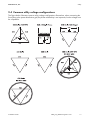
2.4 Common utility voltage configurations
The figure below illustrates common utility voltage configurations. Remember, when connecting the
Sunny Boy to the power distribution grid, the phase relationship is not important, but the voltage must
be compatible.
Installation Guide
SB20_25_30HFUS-eng-IUS113711
17
Unpacking and inspection
SMA America, LLC
3 Unpacking and inspection
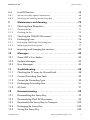
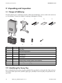
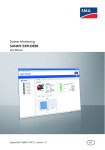
3.1 Scope of delivery
Check the delivery for completeness and for visible external damage, such as cracks in the enclosure
or in the display. Contact your dealer if anything is damaged or missing.
C
B
A
E
D
Gewährleistu
ngs- und Garantie
bedingungen
Bit e f (Name des Gerätes
Typ: ül en Sie die folgenden):
Felder aus:
Datum derSeriennummer:
Instal Anschrift: Inbetriebnahme:
Typ: ationsbetrieb
Datum derSeriIennnummer:
betriebnahme:
Instal atAnschrift:
ionsbetrieb
:
COM
F
Object
A
B
C
D
E
F
G
H
I
G
Quantity
1
1
1
1
1
1
1
1
3
H
I
Description
Sunny Boy
Wall mounting bracket
Installation manual
Document set
User manual
SMA DC-Disconnect
Communication module (SMA Quick Module)
SMA Plug-in Grounding
Screws and washers (M5)
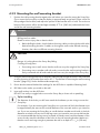
3.2 Identifying the Sunny Boy
You can identify the Sunny Boy using the type label. The type label is on the right side of the enclosure.
The serial number (Serial No.) and the type (Type / Model) of the Sunny Boy are specified on the
type label.
18
SB20_25_30HFUS-eng-IUS113711
Installation Guide
SMA America, LLC
Mounting the Device
4 Mounting the Device
4.1 Safety
DANGER
Danger to life due to fire or explosions.
There is always a certain risk with electric devices that a fire can occur, even though
greatest attention was paid to avoid this during the development.
• Do not install the inverter on flammable construction materials.
• Do not install the inverter in areas where highly flammable materials are stored.
• Do not install the inverter in potentially explosive areas.
WARNING
The Sunny Boy can become hot during operation.
Risk of burns.
• Mount the Sunny Boy in such a way that it cannot be touched inadvertently during
operation.
CAUTION
Danger of crushing due to the Sunny Boy falling.
Crushing of body parts
• Consider the weight of the Sunny Boy with SMA DC-Disconnect of approximately
50 lbs (23 kg) during mounting.
• Always lift the Sunny Boy with both hands.
Installation Guide
SB20_25_30HFUS-eng-IUS113711
19
Mounting the Device
SMA America, LLC
4.2 Selecting the wall mounting location
Observe the following conditions during installation:
• The installation method and mounting location must be suitable for the weight and dimensions
of the Sunny Boy (see section 13 ”Technical Data” (page 103)).
• Mount on a solid surface.
• The mounting location must be accessible at all times. Otherwise proper maintenance of the
Sunny Boy is not possible.
• Vertical installation or tilted backwards by max. 30°.
• The connection area must point downwards.
• Never install the device with a forward tilt.
• Do not install horizontally.
• Install at eye level to allow operating status to be read at all times.
• The ambient temperature must be below +113 °F (+45 °C) to ensure optimal operation.
• Do not expose the Sunny Boy to direct sunlight, in order to avoid power reduction due to
excessive heating.
• In a living area, do not mount the unit on
plasterboard walls (or similar) in order to avoid
audible vibrations.
The Sunny Boy can make noises when in use which
can be regarded as a nuisance when installed in a
living area.
20
SB20_25_30HFUS-eng-IUS113711
Installation Guide
SMA America, LLC
Mounting the Device
• Observe the minimum clearances to walls, other
devices or objects as shown in the diagram in order
to guarantee sufficient heat dissipation.
Overview minimum clearances for indoor installation:
Top
Front
Bottom
12 in. (300 mm)
2 in. (50 mm)
10 in. (250 mm)
For outdoor installation make sure that the Sunny Boy has
a clearance of 3 ft. (90 cm) from ground.
Multiple Sunny Boy units installed in areas with high ambient temperatures
The individual Sunny Boy units must be far enough apart to ensure that the individual
Sunny Boy units do not take in the cooling air of the neighboring unit.
If necessary, increase the clearances and make sure there is enough ventilation to ensure
sufficient cooling of the Sunny Boy units.
Do not install several Sunny Boy inverters on top of each other. The Sunny Boy takes
cooling air in from underneath and blows it out above through the cooling fins. The heated
air disperses upwards. In case several Sunny Boy inverters are installed on top of each
other, the lower Sunny Boy blows the heated air into the Sunny Boy installed above.
This reduces the cooling efficiency and thus the yield of the upper Sunny Boy.
4.3 Mounting the wall mounting bracket
The Sunny Boy is shipped with a wall mounting bracket that is suitable for use with most walls.
The horizontal part of the bracket has 5 holes. Make sure that the wall you choose to mount the
Sunny Boy on is sturdy enough to support its weight (50 lbs./23 kg) over a long period of time and
that the wall is plumb. Be sure to use the appropriate type of mounting hardware for the wall material
and ensure that the hardware is no smaller than 1⁄4 in. (6 mm) in diameter.
Installation Guide
SB20_25_30HFUS-eng-IUS113711
21
Mounting the Device
SMA America, LLC
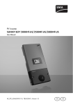
Dimensions of the Wall Mounting Bracket
22
SB20_25_30HFUS-eng-IUS113711
Installation Guide
SMA America, LLC
Mounting the Device
4.3.1 Possibilities for mounting the wall mounting bracket
Mounting on stone wall
For mounting on a stone wall you must affix the wall
mounting bracket with a minimum of 3 screws.
The position of the screws on the wall mounting bracket is
as follows:
• 1 screw on the upper left side of the wall mounting
bracket.
• 1 screw on the upper right side of the wall mounting
bracket.
• 1 screw below on the wall mounting bracket.
Mount the wall mounting bracket as described in section
4.3.2 ”Mounting the wall mounting bracket” (page 24).
Mounting on a wooden wall with a stud
For mounting on a wooden wall with a stud you must affix
the wall mounting bracket with 2 screws. The position of
the screws on the wall mounting bracket is as follows:
• 1 screw at the upper middle of the wall mounting
bracket.
• 1 screw below on the wall mounting bracket.
Mount the wall mounting bracket as described in section
4.3.2 ”Mounting the wall mounting bracket” (page 24).
Installation Guide
SB20_25_30HFUS-eng-IUS113711
23
Mounting the Device
SMA America, LLC
4.3.2 Mounting the wall mounting bracket
1. Position the wall mounting bracket against the wall where you intend to mount the Sunny Boy.
(Try to mount the Sunny Boy so that the display is approximately at eye-level.) Place a level on
the top edge of the bracket, and adjust the position of the bracket until it is level. The enclosure
bottom of the inverter will be located approximately 9 3⁄4 in. (240 mm) underneath the lower
end of the wall mounting bracket.
DANGER
Drilling into live cables.
Death or serious injury due to electric shock.
• Before drilling the holes, check whether electricity cables run through the walls at the
desired mounting location. If cables run through the walls at the desired mounting
location, then select a different mounting location.
CAUTION
Danger of crushing due to the Sunny Boy falling.
Crushing of body parts.
• If mounting onto a wall, ensure that the wall can carry the weight of the Sunny Boy.
• If mounting onto a wooden wall with studs, ensure that the wall mounting bracket is
firmly connected with all studs and the stud can carry the weight of the Sunny Boy.
2. Using the wall mounting bracket as a template, mark the wall through the holes in the horizontal
or vertical portion of the bracket (see section 4.3.1 ”Possibilities for mounting the wall mounting
bracket” (page 23)). Set the bracket aside temporarily.
3. Ensure that the material behind the markings for the drill holes is capable of bearing load.
4. Drill holes at the marks you made on the wall.
5. Insert wall anchors into the drill holes.
DO NOT use molly or toggle bolts to mount the Sunny Boy to sheet rock or panelling.
Tip for installing
The diameter of the holes you drill must match the hardware you are using to mount the
Sunny Boy.
For example, if you are mounting the Sunny Boy to a concrete wall, the hole diameter must
be approximately the same as the outside diameter of the concrete anchors you intend to
use. If you are mounting the Sunny Boy on a wall that has wooden studs inside it, the hole
diameter must be the correct size for the lag screws you intend to use to mount the bracket.
It is recommended that the lag screws be made of stainless steel, and the diameter of the
screws closely match the diameter of the holes in the wall mounting bracket. Make sure
that the screws are long enough to penetrate the wall to a depth of 1 1⁄2 in. (38 mm).
24
SB20_25_30HFUS-eng-IUS113711
Installation Guide
SMA America, LLC
Mounting the Device
6. Insert the screws through the holes in the wall mounting bracket and into the holes you drilled
in the wall.
7. Tighten the screws clockwise until the bracket is held firmly against the wall. Do not overtighten
the screws.
☑ The wall mounting bracket is mounted.
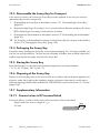
4.4 Mounting the SMA DC-Disconnect
CAUTION
Danger of crushing due to the SMA DC-Disconnect falling.
Crushing of body parts.
• Consider the weight of the SMA DC-Disconnect of approximately 11 lbs (5 kg)
during mounting.
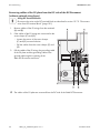
1. Turn the DC disconnect switch of the
SMA DC-Disconnect to position ”Off”.
2. Loosen the screws on the enclosure of the
SMA DC-Disconnect. Do not take the screws out of
the lid.
3. Remove the lid with the screws to the front.
4. Set the lid aside in such a way that it will not
become damaged.
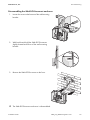
5. Hold the SMA DC‒Disconnect with both hands
slightly slanted. Push both slots of the
SMA DC‒Disconnect to the lower hooks of the
mounting bracket until it clicks.
Installation Guide
SB20_25_30HFUS-eng-IUS113711
25
Mounting the Device
SMA America, LLC
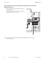
6. Push SMA DC-Disconnect straight onto the wall.
7. Ensure the SMA DC-Disconnect is correctly in
place.
☑ The SMA DC-Disconnect is mounted onto the wall mounting bracket.
26
SB20_25_30HFUS-eng-IUS113711
Installation Guide
SMA America, LLC
Mounting the Device
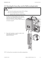
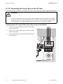
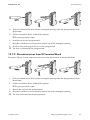
4.5 Mounting the Sunny Boy onto the Wall mounting bracket
CAUTION
The Sunny Boy weighs approximately 40 lbs. (18 kg).
Risk of injury during lifting of the Sunny Boy.
• Always lift the Sunny Boy with both hands.
1. Lift up the Sunny Boy with both hands and hang
from above in the SMA DC-Disconnect and in the
wall mounting bracket. While hanging the
Sunny Boy, ensure that all cables of the inverter do
not become trapped.
2. Ensure the Sunny Boy is correctly in place on the
wall mounting bracket and the
SMA DC‑Disconnect.
☑ The Sunny Boy is mounted onto the wall mounting bracket.
Installation Guide
SB20_25_30HFUS-eng-IUS113711
27
Mounting the Device
SMA America, LLC
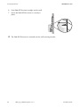
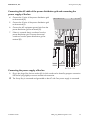
4.6 Grounding the SMA DC-Disconnect
The Sunny Boy is grounded via the connection of the grounding cable to the DC side and
the AC side (see section 6 ”Wiring the Sunny Boy” (page 40)).
To ensure proper grounding of the SMA Disconnect, it must be connected with the
Sunny Boy via an electric conductive connection. This electric conductive connection has
to be provided by a screw and a locking washer included in the scope of delivery.
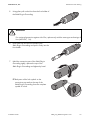
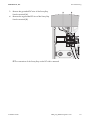
1. Lead the screw with locking washer facing teeth
down into the opening of the Sunny Boy and screw
into the thread of the SMA DC-Disconnect (turn the
screw clockwise).
+
One and Two String
g Wiring
N L1 L2
(for more strings and further
er information see manual)
Negative
gative Grounding
Positive Grounding
GROUNDED
UNGROUNDED
UNGROUNDED
GROUNDED
GROUNDED
Terminal ~
GROUNDED
Terminal
Facing -
=
~
N L1 L2
=
Facing +
+
N L1 L2
+
☑ The SMA DC-Disconnect is connected to the
Sunny Boy via an electric conductive connection.
28
SB20_25_30HFUS-eng-IUS113711
Installation Guide
SMA America, LLC
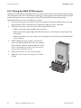
Configuring the Sunny Boy
5 Configuring the Sunny Boy
The Sunny Boy is fitted with the communication interface Quick Module.
You can configure the Quick Module before and after its installation to the Sunny Boy.
5.1 The Quick Module
The inverter is equipped with Bluetooth® Wireless Technology. This allows you to wirelessly request
measurement, event and meter information and to change parameters.
Inside the Quick Module are a slot for a SD card and 3 rotary switches with following functions:
• Rotary switches (A) and (B) for setting the country of installation, the grid type and the display
language (see section 5.1.1 ”Country setting via rotary switch” (page 31)).
• Rotary switch (C) for the allocation of the NetID for communication via
Bluetooth® Wireless Technology (see 5.2.2 ”Configuration for Bluetooth communication”
(page 34)).
Protection against unauthorized access
The inverter is delivered with preset plant passwords. These passwords are the same for
every inverter.
In order to protect the PV plant against unauthorized access, change the preset plant
passwords for the user groups "Installer" and "User" or deactivate Bluetooth completely by
turning the NetID of the inverter to "0" (see section "Configuration for Bluetooth
communication" on page 34).
You can only change the plant passwords using a computer equipped with Bluetooth and
the Sunny Explorer software. The Sunny Explorer user manual describes how to change the
plant passwords. You can download Sunny Explorer free of charge at
www.SMA‑America.com.
Write down the new passwords and inform the user about it.
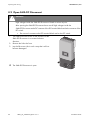
Quick Module 485QM and multi-function relay
You can purchase the Quick Module 485QM with RS485 interface and a multi-function
relay from SMA or your dealer (see section 14 ”Accessories” (page 108)). You will find
detailed descriptions of the functions in the respective manual.
Installation Guide
SB20_25_30HFUS-eng-IUS113711
29
Configuring the Sunny Boy
SMA America, LLC
Identifying the Quick Module
You can identify the Quick Module by its type label. The type label is affixed at the lid of the
Quick Module and shows name, serial number, version and type of the Quick Module.
Inner View of the Quick Module
Object
A
B
C
D
E
Description
Rotary switch for configuration of country and grid type (switch A)
Rotary switch for configuration of language and grid type (switch B)
Rotary switch for configuration of Bluetooth communication
Slot for SD card
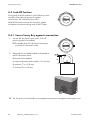
Jumper socket for the configuration of the language to English
Slot for SD card
The Quick Module contains a slot for an SD card. The slot
is on the outside of the Quick Module (A).
• To insert an SD card, flip the lower flap upwards.
In case of a firmware update an SD card is necessary. Contact the SMA Service Line for details.
Properties of the SD Card
• A maximum of 2 GB of storage space.
• Use the SD card exclusively for this Sunny Boy. Do not save any other files on the
SD card.
30
SB20_25_30HFUS-eng-IUS113711
Installation Guide
SMA America, LLC
Configuring the Sunny Boy
5.1.1 Country setting via rotary switch
The switch position 0 / 0 indicates the factory setting. If you have ordered the Sunny Boy with a
certain country or grid setting, the setting is done in the factory via a communication device. The
setting will be overwritten by changes to the rotary switch or via a communication device and can not
be recovered. For orders without a specified installation country or grid type the standard setting is
”US auto” with display language ”German”.
Changes to configuration will immediately be accepted after switching on the line circuit breaker.
If an un-programmed switch setting is selected, the Sunny Boy issues an error message.
• Check whether the Sunny Boy is set to the installation country and grid type using the listed
switch settings in the following table.
• For display language in English set the switch (B) to position "1".
Display Language
Once you have configured the country data set, you can set the display language later
without changing the country data set using rotary switch (B).
Rotary switch positions
The operating parameters show the corresponding parameter set. You can read these off via a
communication device or download them from www.SMA‑America.com.
(A)
0
(B)
0
Parameter Set
Delivery state
Display Language
Delivery state
0
1
as preset
English
0
3
as preset
French
0
4
as preset
Spanish
8
8
8
8
8
8
9
9
9
0
1
2
8
9
A
8
9
A
US 208V without neutral
US 208V without neutral
US 208V without neutral
US 240V without neutral
US 240V without neutral
US 240V without neutral
US auto
US auto
US auto
English
Spanish
French
English
Spanish
French
English
Spanish
French
Installation Guide
Country/grid
dependent on
parameter set
dependent on
parameter set
dependent on
parameter set
dependent on
parameter set
USA
USA
USA
USA
USA
USA
USA
USA
USA
SB20_25_30HFUS-eng-IUS113711
31
Configuring the Sunny Boy
(A)
D
D
D
D
(B)
0
1
2
3
Parameter Set
Off-Grid 60Hz
SMA America, LLC
Display Language
English
German
French
Spanish
Country/grid
flexible
If the Sunny Boy is not set to the correct installation country, configure it via the two rotary switches as
described in section 5.2.2 ”Configuration for Bluetooth communication” (page 34).
Alternatively you can set the settings via the parameters ”CntrySet” or ”Sett.country stand.” using a
communication device, once you have commissioned the Sunny Boy.
If you require adjusted parameter settings for your installation location, you can change these with
the help of a communication device.
32
SB20_25_30HFUS-eng-IUS113711
Installation Guide
SMA America, LLC
Configuring the Sunny Boy
5.2 Configuring the Quick Module
You can configure the Quick Module before connecting it to the Sunny Boy.
The Sunny Boy can be configured in two ways for several countries and grids.
• By using the two rotary switches (A) and (B) of the Quick Module.
• By changing the parameters ”CntrySet” or ”Sett.country stand.” using an external
communication device with Bluetooth interface.
If you don’t want to use Bluetooth communication, deactivate Bluetooth completely by turning the
NetID of the inverter to "0" (see section "Configuration for Bluetooth communication" on page 34).
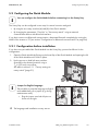
5.2.1 Configuration before installation
If you have not yet installed the Quick Module into the Sunny Boy, proceed as follows for the
configuration:
1. Open the Quick Module by fliping up the lower flap of the Quick Module and opening the lid
of the Quick Module until it locks in place.
2. Set the arrows on both left rotary switches
(A and B) to the desired positions using a
1⁄ in. (2.5 mm) screw driver.
8
See table in section 5.1.1 ”Country setting via
rotary switch” (page 31).
Jumper for English language.
The possibility to swap the language to English
exists additionally via a jumper (e.g. during
maintenance work).
• Plug the jumper onto both left pins as
shown on the right.
☑ The language and installation country are set.
Installation Guide
SB20_25_30HFUS-eng-IUS113711
33
Configuring the Sunny Boy
SMA America, LLC
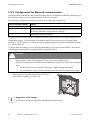
5.2.2 Configuration for Bluetooth communication
Communication via Bluetooth with a communication device is activated as standard. Networking via
Bluetooth with other inverters is deactivated as a delivery condition.
The following configuration settings are possible via a rotary switch (switch C):
Switch position (NetID)
0
1
2 ... F
Setting
Off
Communication via Bluetooth with communication device possible, no
networking with other inverters (factory setting)
Networking with other inverters
In order to restrict communication via Bluetooth between the inverters of your system and those of
neighboring systems, you can assign an individual NetID to the inverters of your system (switch
position 2 ... F). This, however, is only necessary if neighboring systems are to be found within a radius
of 1 640 ft. (500 m).
To ensure that all inverters in your system are detected by your communication device, all inverters
must have the same NetID. To assign a NetID, proceed as follows:
DANGER
High voltages in the inverter. Death or serious injury due to electric shock.
If you have already connected the Quick Module to the Sunny Boy, carry out the following
steps.
• Switch off the line circuit breaker and secure it against being reactivated.
• If a multi-function relay is present, disconnect the multi-function relay power supply.
1. Set the arrow on the right rotary switch (C) using a
screw driver of width 1⁄8 in. (2.5 mm).
Acceptance of the settings
The Bluetooth settings will first be accepted upon commissioning.
34
SB20_25_30HFUS-eng-IUS113711
Installation Guide
SMA America, LLC
Configuring the Sunny Boy
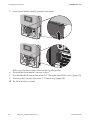
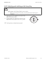
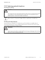
5.2.3 Closing the Quick Module
1. Close the lid of the Quick Module and flip the flap
down.
☑ The Quick Module is closed. You can now mount the Quick Module to the Sunny Boy, as
described in section 5.3 ”Mounting the Quick Module” (page 35).
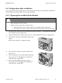
5.3 Mounting the Quick Module
1. If the Sunny Boy is already operating:Disconnect the Sunny Boy from voltage sources
(see section 8.1 ”Disconnect the Sunny Boy from Voltage Sources” (page 65)) and open the
SMA DC Disconnect (see section 8.2 ”Open SMA DC Disconnect” (page 66))
2. Plug the Quick Module into the designated holes on the bracket until it snaps into place.
Installation Guide
SB20_25_30HFUS-eng-IUS113711
35
Configuring the Sunny Boy
SMA America, LLC
3. Push the Quick Module carefully upwards to the stopper.
☑ The lug of the Quick module is flush with the lug of the bracket.
4. Check that the Quick Module is securely in place.
5. Close the SMA DC Disconnect (see section 8.3 ”Closing the SMA DC-Disconnect” (page 67)).
6. Commission the Sunny Boy (see section 7 ”Commissioning” (page 63)).
☑ The Quick Module is mounted.
36
SB20_25_30HFUS-eng-IUS113711
Installation Guide
SMA America, LLC
Configuring the Sunny Boy
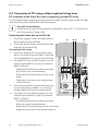
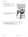
5.4 Configuration after installation
If you would like to make configurations to the Sunny Boy although you already have installed the
Quick Module to the Sunny Boy , then proceed as follows.
5.4.1 Opening the installed Quick Module
DANGER
High voltages inside the inverter
Death or serious injury due to electric shock.
• Switch off the line circuit breaker and secure it against being reactivated.
• If a multi-function relay is present, disconnect the multi-function relay power supply.
1. Disconnect the Sunny Boy from all voltage sources (see section 8.1 ”Disconnect the Sunny Boy
from Voltage Sources” (page 65)).
2. Open the SMA DC Disconnect (see section 8.2 ”Open SMA DC Disconnect” (page 66)).
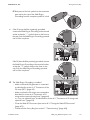
3. Pull the Quick Module carefully downwards to the
stopper.
☑ The Quick Module is completely visible.
4. Flip up the lower flap of the Quick Module and
open the lid.
One
B
B
C
F 01
AB
CDE
AA
6789
Installation Guide
2 3
5 7
and
(for more
Two
Strin
string
One
s and
g Wir
String+and
+ +Two further informing
DC-W
ation
iring
1 2
see manu
Nega
DC -3
tive Grou
al)
DC +
nding
Invert
GRO
er Wire
UND
Positi
UNG
ED
Invert
black
ve Grou
ROUN
er Wire
(-)
nding
DED
UNG
red (+)
PLUGGRO
ROUN
UND
IN GROU
ED
DED
GRO
NDIN
Termi
UND
G
nal =
ED
Termi
Facin
~
nal =
gGRO
UND ~
ED
Facin
g+
5
6. Set the Net ID for Bluetooth communication
(see section 5.2.2 ”Configuration for Bluetooth
communication” (page 34)).
2 3
5 7
23 4
5. Set the installation country and display language
(see section 5.2.2 ”Configuration for Bluetooth
communication” (page 34)).
E
SB20_25_30HFUS-eng-IUS113711
37
Configuring the Sunny Boy
SMA America, LLC
7. Close the lid of the Quick Module.
8. Push the Quick Module carefully upwards to the
stopper.
☑ The lug of the Quick module is flush with the lug of the bracket.
9. Close the SMA DC-Disconnect (see section 6.8 ”Closing the SMA DC Disconnect” (page 62)).
10. Commision the Sunny Boy (see section 7 ”Commissioning” (page 63)).
☑ The country configuration is complete.
38
SB20_25_30HFUS-eng-IUS113711
Installation Guide
SMA America, LLC
Configuring the Sunny Boy
5.5 Disassembling the Quick Module
1. Disconnect the Sunny Boy from voltage sources (see section 8.1 ”Disconnect the Sunny Boy
from Voltage Sources” (page 65)).
2. Open the SMA DC Disconnect (see section 8.2 ”Open SMA DC Disconnect” (page 66)).
3. Pull the Quick Module carefully downwards to the
stopper.
☑ The Quick Module is completely visible.
4. Lay two thumbs on the upper edge of the
Quick Module and carefully push the
Quick Module downwards using your thumbs.
When the Quick Module is at the end of the
bracket, pull the lower edge of the Quick Module
slightly forward.
☑ The Quick Module is loosened from its bracket.
5. Carefully take the Quick Module out of the bracket
to the front.
☑ The Quick Module is disassembled.
Installation Guide
SB20_25_30HFUS-eng-IUS113711
39
Wiring the Sunny Boy
SMA America, LLC
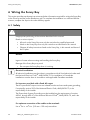
6 Wiring the Sunny Boy
This section provides step-by-step instructions and other information required for wiring the Sunny Boy
to the PV array and the power distribution grid. To complete the installation in a safe and efficient
manner, complete the steps in the order that they appear.
6.1 Safety
DANGER
Inappropriate performing of the activities described in this manual.
Death or serious injuries.
• All work on the Sunny Boy must only be carried out by qualified personnel.
• Work on the Sunny Boy must only be carried out as described in this manual.
• Observe all safety instructions listed on the Sunny Boy, in this manual and those of
the PV plant.
NOTICE
Ingress of water when mounting and installing the Sunny Boy.
Damage of the Sunny Boy may result.
• Do not open the Sunny Boy when it is raining.
Electrical installations
All electrical installations must be done in accordance with all local electrical codes and
the National Electrical Code®, ANSI/NFPA 70. For installation in Canada the
installations must be done in accordance with applicable Canadian standards.
For inverters provided with a fixed AC output
The AC input and AC output circuits are isolated from the enclosure and system grounding,
if required by section 250 of the National Electric Code, ANSI/NFPA 70, is the
responsibility of the installer.
The Photovoltaic System Grounding must be installed per the requirements of sections
690.41 through 690.47 of the National Electrical Code®, ANSI/NFPA 70, and is the
responsibility of the installer.
For optimum connection of the cables to the terminals
Use a 9⁄64 in. x 43⁄4 in. (3.5 mm x 120 mm) screwdriver.
40
SB20_25_30HFUS-eng-IUS113711
Installation Guide
SMA America, LLC
Wiring the Sunny Boy
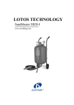
Overview Connection Area
A
grounded
B
ungrounded
+
One and Two String Wiring
N L1 L2
(for more strings and further information see manual)
H
Negative Grounding
Positive Grounding
DC DC +
GROUNDED
UNGROUNDED
UNGROUNDED
GROUNDED
Inverter Wire black (-)
GROUNDED
Terminal ~
GROUNDED
Inverter Wire red (+)
PLUG-IN GROUNDING
Terminal
Facing -
=
~
C
N L1 L2
=
Facing +
+
N
+
L1 L2
G
D
F
Object
A
B
C
D
E
F
G
H
Installation Guide
E
Description
DC side terminals
Connection point grounding Sunny Boy / SMA DC-Disconnect
AC side terminals
Opening for AC cable
Connector for fan power supply
DC-Disconnect Switch
Openings for DC cable
Top-hat rail for optional string fuses
SB20_25_30HFUS-eng-IUS113711
41
Wiring the Sunny Boy
SMA America, LLC
AC Grounding
The Sunny Boy must be connected to the AC ground from the utility via the Ground Terminals
See illustration above (C).
.
PV Grounding
The PV array ground must be connected to the array grounding and DC Grounding Electrode
Conductor – see illustration on page 47. The size for the conductor is usually based on the size of the
largest conductor in the DC system.
DC Grounding Electrode Conductor
A DC grounding electrode conductor may be required by the Authority Having Jurisdiction (AHJ).
Use the array grounding and DC Grounding Electrode Conductor – see illustration on page 47.
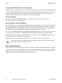
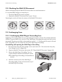
6.2 Lower view of the SMA DC-Disconnect
The following graphic shows the bottom of the SMA DC-Disconnect.
Object
A
B
C
D
E
42
Description
Knob of SMA DC Disconnect
Opening with protective cap (AC side) for 3⁄4 in. (19 mm) cable conduit.
Fan with fan bracket
Handle of the fan bracket
Opening with protective cap (DC side) for 3⁄4 in. (19 mm) cable conduit.
SB20_25_30HFUS-eng-IUS113711
Installation Guide
SMA America, LLC
Wiring the Sunny Boy
6.3 Connection of the PV array (DC)
You can connect two PV strings directly to the terminal of the Sunny Boy. If you need to connect
3 PV strings, fuses as required by the National Electrical Code® may be installed on the hat rail. For
additional information refer to section 6.5 ”Connection of PV strings with optional fuses” (page 50).
WARNING
You must connect the wires that carry the DC voltage from the PV array to the Sunny Boy
in the order described in the following procedure. Deviating from this procedure could
expose you to lethal voltages that can cause serious injury and/or death.
WARNING
PV arrays are energized when exposed to light. Use safe working practices when working
on PV arrays.
WARNING
Always turn OFF all AC breakers and switches in the PV system and wait a minimum of
5 minutes, until the Sunny Boy is completely discharged and all LEDs are off, before
connecting any wires to the Sunny Boy or disconnecting any wires from the Sunny Boy.
Failure to do so could expose you to lethal voltages that can cause serious injury and/or
death.
WARNING
Electric shock as a result of incorrect array grounding before installation of the
SMA Plug-in Grounding. Death or serious injuries.
The PV plant is only grounded when the inverter and the SMA Plug-in Grounding are
completely installed.
Leave the inverter disconnected on both the DC and AC sides until installation of the
inverter and the SMA Plug-in Grounding is completed.
WARNING
Verify that the DC current of your installation does not exceed the maximum values
specified in the type rating label.
Installation Guide
SB20_25_30HFUS-eng-IUS113711
43
Wiring the Sunny Boy
SMA America, LLC
CAUTION
Verify the polarity and the open-circuit voltage from the PV strings before you connect the
DC wires to the Sunny Boy. Applying an open-circuit DC-input voltage that exceeds the
maximum DC-input-voltage range will cause irreversible damage to the Sunny Boy and
void the warranty! Always configure the DC-input-voltage range correctly before
connecting the DC-input wires from the PV array to the Sunny Boy. Use Sunny Design at
www.SMA‑America.com to determine the correct string configuration.
Series fusing may be required depending on the type of PV module and the number of
strings used in the system. See National Electrical Code® 690.9.
Check both the polarity and the open-circuit voltage from the PV strings!
6.3.1 Installing cable conduits and leading cable into the Sunny
Boy
CAUTION
Ground faults, unreliable and resistive connections due to faulty wire nuts.
• Avoid using wire nuts to join any wires together or to make any connections
anywhere in the PV system.
NOTICE
Ingress of water when mounting and installing the Sunny Boy.
Damage to the Sunny Boy will result.
• Do not enlarge openings for the cable conduits. The openings are intended for the
installation of inflexible cable conduits of a size of up to 3⁄4 in. (19 mm).
• For conduit hubs, use only UL Listed raintight, or wet location hubs of type 3R for entry
into the enclosure.
44
SB20_25_30HFUS-eng-IUS113711
Installation Guide
SMA America, LLC
Wiring the Sunny Boy
Installing cable conduit and cable on the DC side
1. Turn the DC disconnect switch of the
SMA DC-Disconnect to position ”Off”.
2. Loosen the screws on the enclosure of the
SMA DC-Disconnect. Do not take the screws out of
the lid.
3. Remove the lid to the front.
4. Lay the lid to one side in such a way that it will not
become damaged.
☑ The SMA DC-Disconnect is open.
5. Push out the protective caps of the openings
through which the DC cables are to be lead from
the inside of the enclosure of the
SMA DC-Disconnect.
6. Install cable conduits (3⁄4 in. (19 mm)) on the free
openings of the SMA DC-Disconnect. Screw the
cable conduits with counter nuts to the inner side of
the SMA DC-Disconnect.
7. Pull the cables of the PV strings and the cable of the
ground rod through the cable conduits.
☑ Cable conduits on the DC side are installed and the cables of the PV strings are lead into the
Sunny Boy.
Installing cable conduit and inserting cable on the AC side
1. Push out the protective caps of the openings through which the AC cables are to be lead from
the inside of the enclosure of the SMA DC-Disconnect.
2. Install cable conduits (3⁄4 in. (19 mm)) on the free openings of the SMA DC-Disconnect.
Screw the cable conduits with counter nuts to the inner side of the SMA DC-Disconnect.
3. Lead the AC cable through the cable conduit from the inside of the safety enclosure into the
inside of the SMA DC-Disconnect.
☑ Cable conduits are installed and the cable for the AC connection are lead into the Sunny Boy.
Installation Guide
SB20_25_30HFUS-eng-IUS113711
45
Wiring the Sunny Boy
SMA America, LLC
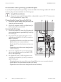
6.4 Connection of PV strings without optional string fuses
DC connection of the Sunny Boy with a negatively grounded PV array
If your PV plant requires negative grounding, connect the cables of the PV strings and the DC cable
of the Sunny Boy to the terminal block in the following way:
Using DC-Terminal blocks
Connect the wires to the DC-terminal block as described in section 12.7.1 ”Connect wires
to DC terminal block” (page 100).
Connecting the Sunny Boy on the DC side
1. Connect the negative inverter wire (black wire) of
the Sunny Boy to the terminal (B).
2. Connect the positive inverter wire (red wire) of the
Sunny Boy to the terminal (C).
Connecting the PV strings
3. Connect the negative DC wires of the PV strings
with a cross-sectional area of of AWG 10 up to but
not including AWG 8 (10 mm²) to the terminal (A).
4. If a negative DC wire of the PV strings has a crosssectional area of AWG 8 (10 mm²) to maximum
AWG 2 (35 mm²):
– Completely loosen the screw of the screw clamp
(F) (turn the screw counterclockwise).
– Feed in the DC wire from below into the screw
clamp.
– Tighten the screw of the screw clamp (turn the
screw clockwise).
5. Connect the positive DC wires of the PV strings with
a cross-sectional area of AWG 10 up to but not
including AWG 8 (10 mm²) to the terminal (D).
6. If a positive DC wire of the PV strings has a crosssectional area of AWG 8 (10 mm²) to maximum
AWG 2 (35 mm²):
– Completely loosen the screw of the screw clamp
(E) (turn the screw counterclockwise).
– Feed in the DC wire from below into the screw clamp.
– Tighten the screw of the screw terminal clockwise.
46
SB20_25_30HFUS-eng-IUS113711
Installation Guide
SMA America, LLC
Wiring the Sunny Boy
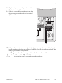
7. Plug the equipment grounding conductor of the
PV plant into terminal (B).
8. If there is a grounding electrode conductor: plug
the grounding electrode conductor into terminal
(A).
+
One and Two String Wiring
iring
(for more strings and further information
rmation see manual)
N L1 L2
Negative
e Grounding
Positive Grounding
GROUNDED
OUNDED
UNGROUNDED
ROUNDED
UNGROUNDED
GROUNDED
GROUNDED
OUNDED
Terminal ~
GROUNDED
Terminal
minal
Facing
cing -
=
~
N L1 L2
=
Facing +
9. Verify that all connections are correctly wired and
properly torqued. Pull the cables in order to make
sure that they are sufficiently fixed.
+
N L1 L2
+
AB
☑ The Sunny Boy is connected on the DC side ready to ground the PV plant negatively.
The grounded conductor may be color coded in accordance with the
National Electrical Code® article 200.
• Use electricians tape for coding the grounded conductor.
Installation Guide
SB20_25_30HFUS-eng-IUS113711
47
Wiring the Sunny Boy
SMA America, LLC
DC connection with a positively grounded PV plant
If your PV plant requires positive grounding, connect the cables of the PV strings and the DC cable of
the Sunny Boy to the terminal block in the following way:
Using DC-Terminal blocks
Connect the wires to the DC-terminal block as described in section 12.7.1 ”Connect wires
to DC terminal block” (page 100).
Connecting the Sunny Boy on the DC side
1. Connect the positive inverter wire (red wire) of the
Sunny Boy to the terminal (B).
2. Connect the negative inverter wire (black wire) of
the Sunny Boy to the terminal (C).
Connecting the PV strings
3. Connect the positive DC wires of the PV strings with
a cross-sectional area of up to AWG 8 (10 mm²) to
the terminal (A).
4. If a positive DC wire of a PV string has a crosssectional area of AWG 8 (10 mm²) to maximum
AWG 2 (35 mm²):
– Completely loosen the screw of the screw clamp
(F) (turn the screw counterclockwise).
– Feed in the DC wire from below into the screw
clamp.
– Tighten the screw of the screw clamp (turn the
screw clockwise).
5. Connect the negative DC wires of the PV strings
with a cross-sectional area of up to AWG 8 (10
mm²) to the terminal (D).
6. If a negative DC wire of a PV string has a crosssectional area of AWG 8 (10 mm²) to maximum
AWG 2 (35 mm²):
– Completely loosen the screw of the screw clamp (E) (turn the screw counterclockwise).
– Feed in the DC wire from below into the screw clamp.
– Tighten the screw of the screw clamp (turn the screw clockwise).
48
SB20_25_30HFUS-eng-IUS113711
Installation Guide
SMA America, LLC
Wiring the Sunny Boy
7. Plug the equipment grounding conductor of the
PV plant into terminal (B).
8. If there is a grounding electrode conductor: plug
the grounding electrode conductor into terminal
(A).
+
One and Two String Wiring
iring
(for more strings and further information
rmation see manual)
N L1 L2
Negative
e Grounding
Positive Grounding
GROUNDED
OUNDED
UNGROUNDED
ROUNDED
UNGROUNDED
GROUNDED
GROUNDED
OUNDED
Terminal ~
GROUNDED
Terminal
minal
Facing
cing -
=
~
N L1 L2
=
Facing +
+
N L1 L2
+
AB
☑ Verify that all connections are correctly wired and properly clamped or torqued. Pull the cables
in order to make sure that they are sufficiently fixed. The Sunny Boy is connected on the DC side
ready to ground the PV plant positively.
The grounded conductor may be color coded in accordance with the
National Electrical Code® article 200.
• Use electricians tape for coding the grounded conductor.
Installation Guide
SB20_25_30HFUS-eng-IUS113711
49
Wiring the Sunny Boy
SMA America, LLC
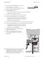
6.5 Connection of PV strings with optional fuses
By using optional fuses for the connection of the PV strings, you can connect up to three PV strings to
the Sunny Boy. For this you must install fuse holders to the top-hat rail next to the terminal block.
Requirements for installing optional fuses
• Only use the fuse holders and fuses specified in section 14 "Accessories" on page 108.
• Use 3 wires with a length of 10 in. (254 mm) and a size of AWG 8 (10 mm²).
These wires are not included in the delivery.
DC connection with a negatively grounded PV plant
Connecting the Sunny Boy on the DC side
Using DC-Terminal blocks
Connect the wires to the DC-terminal block as described in section 12.7.1 ”Connect wires
to DC terminal block” (page 100).
1. Connect the negative inverter wire (black wire) of
the Sunny Boy to the terminal (B).
2. Connect the positive inverter wire (red wire) of the
Sunny Boy to the terminal (C).
Connecting the PV strings
3. Remove the screwless end block from the top-hatrail (left of the DC-terminal block).
4. Mount three fuse holders to the top-hat rail.
5. Install fuses in the fuse holders.
The fuses must be functional and of the correct size.
Refer to section 14 ”Accessories” (page 108) for a
specification of suitable fuses.
6. Put the sticker delivered with the fuse holder plainly
visible near by the fuse holder.
7. Loosen the screws of the lower terminals of the fuses
(G) in a counterclockwise direction.
8. For each positive DC wire of the PV strings:
– Feed in the wire from below into the terminal of
a fuse (G).
– Tighten the terminal screw in a clockwise
direction.
9. Strip the ends of the additional wires on one side in
accordance with the specifications of the fuse
holder manufacturer.
50
SB20_25_30HFUS-eng-IUS113711
Installation Guide
SMA America, LLC
Wiring the Sunny Boy
10. Strip the ends of the additional wires on the other
side to a length of 1⁄2 in. (12 mm).
11. Loosen the screws of the upper terminal of the fuses
(A) in a counterclockwise direction.
12. For each additional wire:
– Feed in the wire from above into the terminal of a fuse holder(A).
– Tighten the terminal screw clockwise.
13. Connect two of the additional wires to the terminals (D).
14. Connect the third additional wire to screw clamp (E):
– Completely open the screw terminal counterclockwise.
– Feed in the wire from below into the screw terminal.
– Tighten the screw clamp clockwise.
15. Connect two of the negative DC wires of the PV strings to the terminals (H).
16. Connect the third negative DC wire of the PV strings to screw terminal (F).
– Completely open the screw clamp counterclockwise.
– Feed in the wire from below into the screw terminal.
– Tighten the screw clamp clockwise.
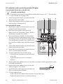
17. Plug the equipment grounding conductor of the
PV plant into terminal (B).
18. If there is a grounding electrode conductor:
plug the grounding electrode conductor into
terminal (A).
+
One and Two String Wiring
iring
(for more strings and further information
rmation see manual)
N L1 L2
Negative
e Grounding
Positive Grounding
GROUNDED
OUNDED
UNGROUNDED
ROUNDED
UNGROUNDED
GROUNDED
GROUNDED
OUNDED
Terminal ~
GROUNDED
Terminal
minal
Facing
cing -
=
~
N L1 L2
=
Facing +
+
N L1 L2
+
☑ Verify that all connections are correctly wired and
properly clamped or torqued. Pull the cables in
order to make sure that they are sufficiently
fixed.The Sunny Boy is connected on the DC side
ready to ground the PV plant negatively.
AB
Installation Guide
SB20_25_30HFUS-eng-IUS113711
51
Wiring the Sunny Boy
SMA America, LLC
DC connection with a positively grounded PV plant
Connecting the Sunny Boy on the DC side
Using DC terminal blocks
Connect the wires to the DC terminal block as described in section 12.7.1 ”Connect wires
to DC terminal block” (page 100).
1. Connect the positive inverter wire (red wire) of the
Sunny Boy to the terminal (B).
2. Connect the negative inverter wire (black wire) of
the Sunny Boy to the terminal (C).
Connecting the PV strings
3. Remove the screwless end block from the top- hatrail (left of the DC terminal block).
4. Mount three fuse holders to the top-hat rail.
Refer to section 14 ”Accessories” (page 108) for a
specification of suitable fuse holders.
5. Ensure that fuses are installed in the fuse holders.
The fuses must be fully operative and of the correct
size. Refer to section 14 ”Accessories” (page 108)
for a specification of suitable fuses. If there are no
functional fuses installed, then install fully operative
fuses.
6. Put the sticker delivered with the fuse holder plainly
visible near by the fuse holder.
7. Loosen the screws of the lower terminals of the fuses
(G) in a counterclockwise direction.
8. For each negative DC wire of the PV strings:
– Feed in the wire from below into the terminal of
a fuse (G).
– Tighten the terminal screw in a clockwise
direction.
9. Strip the ends of the additional wires on one side in accordance with the specifications of the
fuse holder manufacturer.
10. Strip the ends of the additional wires on the other
side to a length of 1⁄3 in. (8 mm).
11. Loosen the screws of the upper terminal of the fuses
(A) in a counterclockwise direction.
12. For each additional wire:
– Feed in the wire from above into the terminal of a fuse holder (A).
– Tighten the terminal screw in a clockwise direction.
52
SB20_25_30HFUS-eng-IUS113711
Installation Guide
SMA America, LLC
Wiring the Sunny Boy
13. Connect two of the additional wires to the terminals (D).
14. Connect the third additional wire to screw clamp (E):
– Completely open the screw clamp (turn the screw counterclockwise).
– Feed in the wire from below into the screw clamp.
– Close the screw clamp (turn the screw clockwise).
15. Connect two of the positive DC wires of the PV strings to the terminals (H).
16. Connect the third positive DC wire of the PV strings to screw clamp (F).
– Completely open the screw clamp (turn the screw counterclockwise).
– Feed in the wire from below into the screw clamp.
– Close the screw clamp (turn the screw clockwise).
17. Plug the equipment grounding conductor of the
PV plant into terminal (B).
18. If there is a grounding electrode conductor:
plug the grounding electrode conductor into
terminal (A).
+
One and Two String Wiring
iring
(for more strings and further information
rmation see manual)
N L1 L2
Negative
e Grounding
Positive Grounding
GROUNDED
OUNDED
UNGROUNDED
ROUNDED
UNGROUNDED
GROUNDED
GROUNDED
OUNDED
Terminal ~
GROUNDED
Terminal
minal
Facing
cing -
=
~
N L1 L2
=
Facing +
+
N L1 L2
+
AB
☑ Verify that all connections are correctly wired and properly torqued. Pull the cables in order to
make sure that they are sufficiently fixed. The Sunny Boy is connected on the DC side ready to
ground the PV plant positively.
Installation Guide
SB20_25_30HFUS-eng-IUS113711
53
Wiring the Sunny Boy
SMA America, LLC
6.6 Installation of the SMA Plug-in Grounding
SMA Plug-in Grounding enables for array grounding and contains a fuse for Ground Fault Indication
(GFDI). If a ground fault occurs, the fuse in the SMA Plug-in Grounding disconnects the fault current
generated.
The type of grounding (positive/negative) is coded into the grounding stick.
The SMA Plug-in Grounding must be installed according to the desired array grounding before
commissioning the Sunny Boy.
DANGER
Danger of electric shock caused by damaged SMA Plug-in Grounding.
If the SMA Plug-in Grounding is damaged water can enter into it. Contact with high voltage
possible.
• Check Plug-in Grounding before installation.
• Do not install a damaged Plug-in Grounding.
• If the Plug-in Grounding fell down and no damage is visible but you doubt its proper
functionality, replace it with a new one.
Changing operating parameter for grounding of the Sunny Boy
The operating parameter of the Sunny Boy is preset to negative grounding.
When the grounding of the Sunny Boy must be changed to positive grounding you must
change the operating parameter ”Cntry.Mdul.GndModReq” of the Sunny Boy via a
communication product.
Installing the SMA Plug-in Grounding
1. Disconnect the Sunny Boy from voltage sources (see section 8.1 ”Disconnect the Sunny Boy
from Voltage Sources” (page 65)).
2. Open the SMA DC Disconnect (see section 8.2 ”Open SMA DC Disconnect” (page 66)).
3. Check whether the SMA Plug-in Grounding is
screwed together: hold the connection part of the
SMA Plug-in Grounding firmly and screw on the
cap of the SMA Plug-in Grounding by hand.
54
SB20_25_30HFUS-eng-IUS113711
Installation Guide
SMA America, LLC
Wiring the Sunny Boy
☑ Both parts of the lock symbol on the connection
part and on the cap of the SMA Plug-in
Grounding form the complete symbol of a lock.
4. If the PV array shall be negatively grounded:
connect the SMA Plug-in Grounding to the terminal
socket so that the ”‒” symbol shows to the front on
the cap. Push the SMA Plug-in Grounding upwards
until it clicks into place.
grounded
ungrounded
+
One and Two String Wiring
(for more strings and further information see manual)
Negative Grounding
Positive Grounding
DC DC +
GROUNDED
UNGROUNDED
UNGROUNDED
GROUNDED
Inverter Wire black (-)
GROUNDED
Inverter Wire red (+)
Terminal
Facing -
Terminal ~
GROUNDED
PLUG-IN GROUNDING
N L1 L2
N L1 L2
=
=
~
Facing +
+
N L1 L2
+
If the PV plant shall be positively grounded: connect
the SMA Plug-in Grounding to the terminal socket
so that the ”+” symbol shows to the front on the
cap. Push the SMA Plug-in Grounding upwards
until it clicks into place.
☑ The SMA Plug-in Grounding is installed.
– Make sure that the PV-generator is connected
as described in section 6.3 ”Connection of the
PV array (DC)” (page 43).
N L1 L2
grounded
ungrounded
+
One and Two String Wiring
(for more strings and further information see manual)
Negative Grounding
Positive Grounding
DC DC +
GROUNDED
UNGROUNDED
UNGROUNDED
GROUNDED
Inverter Wire black (-)
GROUNDED
Inverter Wire red (+)
Terminal
Facing -
Terminal ~
GROUNDED
PLUG-IN GROUNDING
=
~
N L1 L2
N L1 L2
=
Facing +
+
N L1 L2
+
– Make sure that the PV strings are connected as
described in section 6.4 ”Connection of PV
strings without optional string fuses” (page 46)
or, if you use optional fuses, as described in section 6.5 ”Connection of PV strings with
optional fuses” (page 50).
– Close the SMA DC Disconnect (see section 8.3 ”Closing the SMA DC-Disconnect”
(page 67)).
– Commission the Sunny Boy (see section 7 ”Commissioning” (page 63)).
Installation Guide
SB20_25_30HFUS-eng-IUS113711
55
Wiring the Sunny Boy
SMA America, LLC
6.6.1 Configurable Grounding Parameters
Parameter names according to the type of communication
Depending on the communication type (Bluetooth or RS485), the inverter uses a different
communication protocol and the parameters are displayed differently.
• Communication via Bluetooth and Sunny Explorer: DATA II+
• Communication via RS485: DATA I
Two parameters are important for the grounding of the PV plant. You can configure these parameters
in the inverter via a communication device or a PC with the appropriate software.
• Parameter "Module grounding prescribed?" (DATA II+) or "Md.GndMdt" (DATA I)
• Parameter "Prescribed grounding type" (DATA II+) or "Md.GndModReq" (DATA I)
6.6.2 Parameter "Module grounding prescribed?" or "GndMdt"
The grounding module in the inverter is configured via the parameter "Module grounding
prescribed?" or "Md.GndMdt". Make sure you comply with the requirements of the module
manufacturer as well as the regulations applicable at the installation location of the PV plant.
There are two configuration possibilities:
Value
Explanation
Default Value
(DATA II+ / DATA I)
(DATA II+ / DATA I)
No
not available
Yes
Yes
Grounding is prescribed by normative regulation
or the module manufacturer. The inverter can only
be operated with an SMA Plug-in Grounding set.
In case of a grounding error, the inverter will not
continue to feed into the grid and interrupts
operation. The inverter displays a warning with the
event number "35" in case of an insulation error.
56
SB20_25_30HFUS-eng-IUS113711
Installation Guide
SMA America, LLC
Wiring the Sunny Boy
6.6.3 Error Messages
Always correct errors
Immediately correct errors, even if the inverter continues to feed into the grid.
The inverter behaves differently, depending on the configuration of the parameter "Module grounding
prescribed?" or "MdGndMdt".
The following error messages may occur:
Parameter "Module grounding prescribed?" / "MdGndMdt"
Configuration: Yes
Cause / Correction
• Event number 35
• Display message
< Ground fuse fault - check ground fuse >
• Red LED glows continuously.
An overcurrent has occurred.
• Correct the error as described in
section 11.2 ”Correct Grounding Fuse
Fault” (page 89).
• Green LED blinks or disappears.
• The inverter does not feed into the grid.
• Event number 35
• Display message
< Insulation resist. - check generator >
• Red LED glows continuously.
• Green LED blinks or disappears.
• The inverter does not feed into the grid.
• Event number 42
• Display message
< Wrong earthing type; check earthing set >
• Red LED glows continuously.
• Green LED blinks or disappears.
• The inverter does not feed into the grid.
Installation Guide
An insulation fault has occurred.
• If an SMA Plug-in Grounding is
installed, correct the fault as described
in section 11.2 ”Correct Grounding
Fuse Fault” (page 89).
• If the SMA Plug-in Grounding is
missing, connect the
SMA Plug-in Grounding as described
in section 6.6 ”Installation of the SMA
Plug-in Grounding” (page 54).
The SMA Plug-in Grounding has been
connected incorrectly (reverse polarity) or is
missing.
• Correct the error as described in
section 11.3 ”Correct the Grounding
Type” (page 90).
SB20_25_30HFUS-eng-IUS113711
57
Wiring the Sunny Boy
SMA America, LLC
Parameter "Module grounding prescribed?" / "MdGndMdt"
Configuration: No
Cause Correction
• Event number 42
• Display message
< Wrong earthing type; check earthing set >
• Red LED glows continuously.
• Green LED glows continuously.
• The inverter feeds into the grid.
The SMA Plug-in Grounding has been
connected incorrectly (reverse polarity) or is
missing.
• Correct the error as described in
section 11.3 ”Correct the Grounding
Type” (page 90).
6.6.4 Parameter "Prescribed grounding type" or
"Md.GndModReq"
Via the parameter "Prescribed grounding type" or "Md.GndModReq" you will be able to specify the
required grounding type. Default configuration for the parameter is "Negative".
There are two ways to specify this parameter:
• Automatically: When in learning mode, the inverter automatically saves the grounding type
of the plugged in SMA Plug-in Grounding after 10 hours of operation.
• Manually: You can change the grounding type you want to use via the communication tool
(Bluetooth/RS485), after you have started up the inverter. It is also possible to manually
configure the parameter without the SMA Plug-in Grounding.
There are four configuration options:
Value
(DATA II+ / DATA I)
Positive / GndModPs
Negative / GndModNg
None prescribed /
GndModNoneReq
Learning / GndModLrn
Explanation
The inverter only allows positive grounding.
The inverter only allows negative grounding.
No specific grounding mode is required.
Default Value
(DATA II+ / DATA I)
Negative /
GndModNg
The inverter detects the grounding and, after
10 hours of operation with the plugged in SMA
Plug‑in Grounding, saves the grounding type.
The inverter can be operated with or without
grounding.
58
SB20_25_30HFUS-eng-IUS113711
Installation Guide
SMA America, LLC
Wiring the Sunny Boy
6.7 Wiring the AC Output
This subsection provides complete, step-by-step procedures for wiring the AC output from the Sunny
Boy to the power distribution grid.
6.7.1 AC connection safety requirements
WARNING
All electrical installations must be done in accordance with all local electrical codes and
with the National Electrical Code®, ANSI/NFPA 70. Use 6 AWG (maximum), 194 °F
(90 °C), copper wire for all AC wiring connections to the Sunny Boy. Voltage drop and
other considerations may dictate that larger size wires be used. Use only solid wire or
stranded wire.
WARNING
The National Electrical Code® states that the inverter must be connected to a dedicated
circuit, and that no other outlets or devices can be connected to the same circuit. See
National Electrical Code® section 690-64(b)(1). The National Electrical Code® also
imposes limitations on the size of the inverter and the manner in which it is connected to the
power distribution grid. See National Electrical Code® section 690-64(b)(2).
WARNING
Before connecting the Sunny Boy to the electrical power distribution grid, contact the local
utility company. This connection must be made only by qualified personnel.
WARNING
To reduce the risk of fire, connect only to a circuit provided with the required branch circuit
overcurrent device sized in accordance with the National Electrical Code®, ANSI/NFPA
70. The maximum size overcurrent device shall not be more than 20 amperes.
Installation Guide
SB20_25_30HFUS-eng-IUS113711
59
Wiring the Sunny Boy
SMA America, LLC
6.7.2 Connecting the Sunny Boy on the AC side
Use the following procedure to connect the AC wires to the Sunny Boy with the SMA DC-Disconnect:
WARNING
You must connect the wires that carry the AC voltage from the Sunny Boy to the power
distribution grid in the order described in this procedure. Deviating from this procedure
could expose you to lethal voltages that can cause serious injury and/or death.
Connecting the AC output of the Sunny Boy to the terminal block
1. Connect the N wire (white wire) of the Sunny Boy
to the terminal (A).
2. Connect the L1 wire (black wire) of the Sunny Boy
to the terminal (B).
3. Connect the L2 wire (red wire) of the Sunny Boy to
the terminal (C).
60
SB20_25_30HFUS-eng-IUS113711
Installation Guide
SMA America, LLC
Wiring the Sunny Boy
Connecting the AC cable of the power distribution grid and connecting the
power supply of the fan
4. Connect the L1 wire of the power distribution grid
to the terminal (E).
5. Connect the L2 wire of the power distribution grid
to the terminal (F).
6. Connect the AC equipment ground wire from the
power distribution grid to terminals (G).
7. If there is a neutral electic conductor from the
power distribution grid: Connect the neutral
conductor from the power distribution grid to
One and Two String Wiring
iring
terminal (D).
+
(for more strings and further information
rmation see manual)
Positive Grounding
GROUNDED
OUNDED
UNGROUNDED
ROUNDED
UNGROUNDED
GROUNDED
GROUNDED
OUNDED
Terminal ~
GROUNDED
Terminal
minal
Facing
cing -
Connecting the power supply of the fan
N L1 L2
Negative
e Grounding
=
~
N L1 L2
=
Facing +
A
+
N L1 L2
+
BCD E F G
8. Plug in the plug of the fan into socket (A). A click sound can be heard by propper connection.
Pull the fan plug slightly to ensure mechanical connection.
☑ The Sunny Boy is connected and grounded on the AC side. Fan power supply is connected.
Installation Guide
SB20_25_30HFUS-eng-IUS113711
61
Wiring the Sunny Boy
SMA America, LLC
6.8 Closing the SMA DC Disconnect
When you have finished connecting the DC input wires, the AC output wires and the fan power supply
recheck all the connections to ensure that everything is in the right place and that all connections and
knockout fittings are secure and properly torqued. Check all of the knockout fittings of the
SMA DC-Disconnect to ensure that they are in place.
1. Check wire routing to ensure that no wires can interfere with proper sealing of the cover and
that no pressure will be exerted on the connections when the cover is replaced.
2. Carefully position the cover on the front of the SMA DC-Disconnect.
– Make sure that the switch handle snaps into place.
– Make sure that the upper edge of the DC-Disconnect is covered by the lower edge of the
Sunny Boy.
– Make sure that the two screws in the cover are aligned correctly with the two threaded holes
in the enclosure.
3. While holding the cover in place, insert the two
screws into the threaded holes in the case and turn
them clockwise until they are hand-tight. Be careful
not to cross-thread any of the screws. Do not use
power tools to fasten the screws.
4. Verify that the cover is in the correct position.
5. Tighten the cover screws to a torque of 53 in-lbs.
(6 Nm).
62
SB20_25_30HFUS-eng-IUS113711
Installation Guide
SMA America, LLC
Commissioning
7 Commissioning
#
WARNING
Follow the steps in the commissioning procedure in the order they are presented. Deviating
from these procedures could expose you to lethal voltages that can cause serious injury
and/or death.
CAUTION
Follow the steps in the commissioning procedure in the order they are presented. Deviating
from these procedures could cause irreversible damage to the Sunny Boy and void the
warranty.
All Sunny Boy inverters have a sophisticated system for detecting and responding to PV array ground
faults as required by National Electrical Code® section 690.5. The PV array normally operates in a
grounded configuration. Depending on the type of system, the array’s negative or positive conductor
is connected to the grounding system inside the inverter through the SMA Plug-in Grounding as a part
of the UL1741 listed ground fault detection system. The GFDI protection is active whenever there is
sufficient DC voltage to turn on the LCD in the Sunny Boy.
To commission the Sunny Boy, follow these simple instructions:
1. Make sure any covering placed over the PV array is removed.
2. If a multi-function relay is present, connect the multi-function relay power supply.
3. Connect the grid voltage to the Sunny Boy by switching on the main AC circuit breaker in the
main utility panel.
4. Switch the SMA DC-Disconnect to position ”On”.
Installation Guide
SB20_25_30HFUS-eng-IUS113711
63
Commissioning
SMA America, LLC
Display messages during initialization
• First, the firmware version of the internal processors
appears in the text lines.
• After 5 seconds or after tapping the enclosure lid
the serial number or the identifier of the inverter
appears. This identifier can be changed with a
communications device.
• After another 5 seconds, or when you tap again,
the configured standard and the grid type are
displayed.
• After another 5 seconds, or when you tap again,
the configured language is displayed.
• In normal operation the scrolling lines are
subsequently empty. You can refer to the possible
event messages in the scrolling lines and their
meaning in section 10 ”Messages” (page 82).
If there is a ground fault in the array before DC is switched on, the messages ”Insulation
Failure” and ”Check Generator” will be displayed in turns and the GFDI fuse may clear.
If there is a ground fault in the array while DC is switched on, the messages ”Ground Fuse
Fault” and ”Check Ground Fuse” will be displayed in turns.
• If these error messages are encountered, switch off the DC and AC disconnects to
the Sunny Boy and troubleshoot the array.
Refer to section "Checking the PV array for Ground Fault" on page 88.
If the Sunny Boy is not operating as expected after the commissioning procedure has been
completed, refer to Section 10 ”Messages” (page 82) and to
section 11 ”Troubleshooting” (page 88).
If there is adequate sun irradiation and the resulting PV input voltage is greater than
220 V DC, the Sunny Boy will automatically begin feeding power to the power distribution
grid.
Anytime the AC power is disconnected from the inverter, either manually or as a result of
an AC disturbance, the inverter will wait 5 minutes after the AC power has been restored
to reconnect. When servicing the inverter, always disconnect the AC first, then switch off
the DC-Disconnect.
64
SB20_25_30HFUS-eng-IUS113711
Installation Guide
SMA America, LLC
Opening and closing
8 Opening and closing
8.1 Disconnect the Sunny Boy from Voltage Sources
DANGER
Electric shock due to improper opening of the SMA DC-Disconnect. Death resulting from
burning and electric shock.
• Observe the sequence described here when opening the Sunny Boy.
• If problems occur when performing the work described here, contact SMA.
1. Set the line circuit breaker on the AC side to position ”Off” and secure against reconnection.
2. If a multi-function relay is present, disconnect the multi-function relay power supply.
3. Turn the DC disconnect switch to position ”Off” and
wait 5 minutes, until the capacitors of the Sunny
Boy are discharged all LEDs are off.
Installation Guide
SB20_25_30HFUS-eng-IUS113711
65
Opening and closing
SMA America, LLC
8.2 Open SMA DC Disconnect
DANGER
High voltages inside the SMA DC-Disconnect. Death or serious injuries.
After opening the SMA DC-Disconnect there are still high voltages inside the
SMA DC-Disconnect at the DC contacts of the DC terminal block and at the contacts of the
DC switch.
• Do not touch contacts at the DC terminal block and on the DC switch.
1. Turn and loosen the screws on the enclosure of the
SMA DC-Disconnect in a counterclockwise
direction.
2. Remove the lid to the front.
3. Lay the lid to one side in such a way that it will not
become damaged.
☑ The SMA DC-Disconnect is open.
66
SB20_25_30HFUS-eng-IUS113711
Installation Guide
SMA America, LLC
Opening and closing
8.3 Closing the SMA DC-Disconnect
Recheck all your connections to ensure that everything is in the right place and that all connections
and knockout fittings are secure and properly torqued. Check all of the knockout fittings of the
SMA DC-Disconnect to ensure that they are in place.
1. Check wire routing to ensure that no wires can interfere with proper sealing of the cover and
that no pressure will be exerted on the connections when the cover is replaced.
2. Carefully position the cover on the front of the SMA DC-Disconnect.
– Make sure that the switch handle snaps into place.
– Make sure that the upper edge of the SMA DC-Disconnect is covered by the lower edge of
the Sunny Boy.
– Make sure that the two screws in the cover are aligned correctly with the two threaded holes
in the enclosure.
3. While holding the cover in place, insert the two
screws into the threaded holes in the enclosure and
turn them until they are hand-tight. Be careful not to
cross-thread any of the screws. Do not use power
tools to fasten the screws.
4. Verify that the cover is in the correct position.
5. Tighten the cover screws to a torque of 53 in-lbs.
(6 Nm).
☑ The SMA DC-Disconnect is closed.
Installation Guide
SB20_25_30HFUS-eng-IUS113711
67
Opening and closing
SMA America, LLC
8.4 Lock-Off function
During work on the PV modules in your PV plant you must
switch the Sunny Boy off and secure against
reconnection. The Lock-Off function of the
SMA DC-Disconnect secures the Sunny Boy against
accidental reconnection during work on the PV plant.
8.4.1 Secure Sunny Boy against reconnection
1. Turn the DC disconnect switch to the ”Lock off”
position (symbol of a padlock).
☑ The handle of the DC disconnect switch pops
out of the DC disconnect switch.
2. Hang and lock a suitable padlock in the handle of
the DC disconnect switch.
Dimensions of the padlock:
A: maximum diameter of the shackle: 1⁄4 in. (6 mm)
B: maximum 7⁄10 in. (18 mm)
C: minimum 5⁄8 in. (16 mm)
☑ The Sunny Boy is mechanically secured against reconnection and against removing the cover.
68
SB20_25_30HFUS-eng-IUS113711
Installation Guide
SMA America, LLC
Opening and closing
8.4.2 Unlocking and switching on the Sunny Boy
WARNING
High voltages in the PV plant. Death or serious injuries.
• Before reconnecting the Sunny Boy, ensure that all work on the PV sytem is
completed.
1. Open and remove the padlock on the switch of the
SMA DC-Disconnect switch.
2. Push the handle of the SMA DC-Disconnect into the
SMA DC-Disconnect and turn to the ”On” position.
☑ The Sunny Boy is unlocked and connected.
Installation Guide
SB20_25_30HFUS-eng-IUS113711
69
Maintenance and cleaning
SMA America, LLC
9 Maintenance and cleaning
Check the correct operation of the Sunny Boy at regular intervals.
Impurities such as dust or pollen can cause heat accumulation that can lead to yield losses. Also check
the Sunny Boy and the cables for visible external damage. Undertake repairs if necessary.
9.1 Checking Heat Dissipation
If the Sunny Boy regularly reduces its output due to too high heat (temperature symbol on the display
illuminates), this can be caused by the following:
CAUTION
The cooling fins of the Sunny Boy become hot during operation.
Burn injuries will result when touching the fins.
• Wait for the Sunny Boy to cool down, before checking the heat dissipation.
• The cooling fins on the rear side of the enclosure are clogged with dirt.
– Clean the cooling fins with a soft brush.
• The fan is clogged with dirt.
– Clean the fan.
70
SB20_25_30HFUS-eng-IUS113711
Installation Guide
SMA America, LLC
Maintenance and cleaning
9.1.1 Cleaning the fan
If the fan enclosure is soiled with loose dust, it can be cleaned using a vacuum cleaner. For locating
the fan refer to section "Lower view of the SMA DC-Disconnect" on page 42.
If you do not achieve satisfactory results with a vacuum cleaner, you can dismantle the fan for
cleaning.
If the enclosure and fan are dirtier, proceed as follows:
1. Disconnect the Sunny Boy from voltage sources (see section 8.1 ”Disconnect the Sunny Boy
from Voltage Sources” (page 65)).
2. Open the SMA DC Disconnect (see section 8.2 ”Open SMA DC Disconnect” (page 66)).
3. Unlock (1) and pull out (2) the fan socket.
4. Pull the handle of the fan bracket carefully
downwards, until the fan bracket is pulled out of its
guide rail.
☑ The fan and fan bracket are removed.
NOTICE
Damage to the fan during cleaning with compressed air.
• For cleaning the fan, only use a soft brush, a paint brush or a damp cloth.
Installation Guide
SB20_25_30HFUS-eng-IUS113711
71
Maintenance and cleaning
SMA America, LLC
5. Clean the fan with a soft brush, a paint brush, or a
damp cloth.
6. Insert the fan and the fan bracket into the guide rail
and push upwards.
7. Plug the fan plug into the socket. A click sound can
be heard by propper connection. Pull the fan plug
slightly to ensure proper connection.
8. Close SMA DC-Disconnect (see section 8.3 ”Closing the SMA DC-Disconnect” (page 67).
9. Commission the Sunny Boy (see section 7 ”Commissioning” (page 63)).
☑ The fan has been cleaned.
72
SB20_25_30HFUS-eng-IUS113711
Installation Guide
SMA America, LLC
Maintenance and cleaning
9.1.2 Checking the Fan
Checking the Fan
In order to check the fan you need a special data acquisition device (e.g. Sunny WebBox)
or a PC with the appropriate software (e.g. Sunny Explorer) in order to be able to change
the parameters of the Sunny Boy.
You will also need the installer password to access the installer mode.
1. Request the installer password from the SMA Service Line (contact info see page 109).
2. Set the ”CoolSys.FanTst” parameter to ”on” in the installer mode using a communications
device (e.g. Sunny WebBox, Sunny Explorer).
3. Check the air-flow of the fan. The Sunny Boy takes cooling air in from underneath and then
blows it out through the cooling fans. Listen for any unusual noise, which could indicate incorrect
installation or that the fans are faulty.
4. After the test, set the parameter ”CoolSys.FanTst” back to position ”Off”.
☑ The fan has been checked.
Installation Guide
SB20_25_30HFUS-eng-IUS113711
73
Maintenance and cleaning
SMA America, LLC
9.2 Checking the SMA DC Disconnect
When used appropriatly the SMA DC Disconnect does not need maintenance.
It is recommended, though not compulsory to:
• Check the SMA DC Disconnect regularly.
• Operate the SMA DC Disconnect once a year 10 times.
Operating the switch will clean the contacts of the SMA DC Disconnect.
9.3 Exchanging fuses
9.3.1 Exchanging SMA Plug-in Grounding fuse
SMA Plug-in Grounding enables for array grounding and contains a fuse for Ground Fault Indication
(GFDI). If a ground fault occurs, the fuse in the SMA Plug-in Grounding disconnects the fault current
generated. Once the ground fault is eliminated (see section 11.1 ”Checking the PV array for Ground
Fault” (page 88)), you must replace the fuse of the SMA Plug-in Grounding.
Dismantling and opening the SMA Plug-in Grounding
1. Disconnect the Sunny Boy from voltage sources (see section 8.1 ”Disconnect the Sunny Boy
from Voltage Sources” (page 65)).
2. Open the SMA DC Disconnect (see section 8.2 ”Open SMA DC Disconnect” (page 66)).
3. Remove the SMA Plug-in Grounding. Turn it in
counterclockwise direction and then pull it down.
☑ The SMA Plug-in Grounding is loosened from its
bracket.
4. Hold the connection part of the SMA Plug-in
Grounding tightly, loosen and remove the cap of
the SMA Plug-in Grounding.
74
SB20_25_30HFUS-eng-IUS113711
Installation Guide
SMA America, LLC
Maintenance and cleaning
5. Using pliers pull out the fuse from the fuse holder of
the SMA Plug-in Grounding.
WARNING
For continued protection against risk of fire, replace only with the same type and ratings of
fuse (600 VDC, 1 A).
6. Insert new fuse into the fuse holder of the
SMA Plug-in Grounding and push it firmly into the
fuse holder.
7. Hold the connection part of the SMA Plug-in
Grounding tightly, replace the cap of the
SMA Plug-in Grounding and tighten by hand.
☑ Both parts of the lock symbol on the
connection part and on the cap of the
SMA Plug-in Grounding form the complete
symbol of a lock.
Installation Guide
SB20_25_30HFUS-eng-IUS113711
75
Maintenance and cleaning
SMA America, LLC
8. If the PV plant shall be negatively grounded and is
properly wired as described in section 6.3, section
6.4 and section 6.5: connect the SMA Plug-in
Grounding to the terminal socket so that the ”—”
symbol shows to the front on the cap. Push the
SMA Plug-in Grounding upwards until it clicks into
place.
grounded
ungrounded
+
One and Two String Wiring
(for more strings and further information see manual)
Negative Grounding
Positive Grounding
DC DC +
GROUNDED
UNGROUNDED
UNGROUNDED
GROUNDED
Inverter Wire black (-)
GROUNDED
Inverter Wire red (+)
Terminal
Facing -
Terminal ~
GROUNDED
PLUG-IN GROUNDING
N L1 L2
N L1 L2
=
=
~
Facing +
+
N L1 L2
+
9. If the PV plant shall be positively grounded and is
properly wired as described in section 6.3, section
6.4 and section 6.5: connect the SMA Plug-in
Grounding to the terminal socket so that the ”+”
symbol shows to the front on the cap. Push the
SMA Plug-in Grounding upwards until it clicks into
place.
10. Close the SMA DC-Disconnect (see section
8.3 ”Closing the SMA DC-Disconnect” (page 67)).
11. Commission the Sunny Boy (see section
7 ”Commissioning” (page 63)).
N L1 L2
grounded
ungrounded
+
One and Two String Wiring
(for more strings and further information see manual)
Negative Grounding
Positive Grounding
DC DC +
GROUNDED
UNGROUNDED
UNGROUNDED
GROUNDED
Inverter Wire black (-)
GROUNDED
Inverter Wire red (+)
Terminal
Facing -
Terminal ~
GROUNDED
PLUG-IN GROUNDING
=
~
N L1 L2
N L1 L2
=
Facing +
+
N L1 L2
+
☑ The SMA Plug-in Grounding fuse is changed.
76
SB20_25_30HFUS-eng-IUS113711
Installation Guide
SMA America, LLC
Maintenance and cleaning
9.3.2 Replacing optional string fuses
PV String Fuse Sizing
CAUTION
The string fuse size must not be greater than the maximum fuse size rating of the PV module
as provided on the PV module manufacturers data sheet. If no maximum fuse size is
indicated, please contact the PV module manufacturer!
Refer to section 14 ”Accessories” (page 108) for a specification of suitable fuses.
DC Disconnect Requirements
National Electrical Code® 690.15-18 allows the use of fuse holders as a suitable means of
disconnecting PV arrays for servicing. Additional DC disconnects external to the inverter may be
required by the local authority having jurisdiction.
WARNING
Never remove a fuse while it is under load. Electrical arcing and damage to the fuse holder
will occur if a fuse is removed under load.
Installation Guide
SB20_25_30HFUS-eng-IUS113711
77
Maintenance and cleaning
SMA America, LLC
Replacing string fuses
WARNING
The PV string fuses become hot during operation.
Burn injuries will result when touching the fuses.
• Wait for the fuses to cool down, after switching off the line circuit breaker and turning
the DC-Disconnect switch to position ”Off”.
1. Disconnect the Sunny Boy from voltage sources (see section 8.1 ”Disconnect the Sunny Boy
from Voltage Sources” (page 65)).
2. Open the SMA DC Disconnect (see section 8.2 ”Open SMA DC Disconnect” (page 66)).
3. Open fuse holder.
4. Take the fuse out of the fuse holder.
78
SB20_25_30HFUS-eng-IUS113711
Installation Guide
SMA America, LLC
Maintenance and cleaning
WARNING
For continued protection against risk of fire, replace only with the same type and ratings of
fuse.
5. Insert new fuse into the fuse holder.
6. Close fuse holder.
7. Repeat the replacement of fuse for each string.
8. Close the SMA DC-Disconnect (see section 8.3 ”Closing the SMA DC-Disconnect” (page 67)).
9. Commission the Sunny Boy (see section 7 ”Commissioning” (page 63)).
☑ The string fuses have been replaced.
Installation Guide
SB20_25_30HFUS-eng-IUS113711
79
Maintenance and cleaning
SMA America, LLC
9.4 Inspecting and changing the varistors
Varistors are used to protect circuits against excessive transient voltages by incorporating them into
the circuit in such a way that, when triggered, they will shunt the current created by the high voltage
away from the sensitive components. Varistors are designed according to the expected product use.
Their functionality may diminish with following repeated responses as a result of overvoltages. It is
therefore possible that one of the varistors has lost its protective function.
Inspect and change the varistors in the following manner:
1. Disconnect the Sunny Boy from voltage sources (see section 8.1 ”Disconnect the Sunny Boy
from Voltage Sources” (page 65)).
2. Open the SMA DC Disconnect (see section 8.2 ”Open SMA DC Disconnect” (page 66)).
3. The position of the varistors are shown in the figure
(A).
Inspect the varistors for discoloration or other signs
of visual damage. Furthermore test the varistors
with an ohmmeter: when the resistance of the
varistor is nearly or equal 0, the varistor is
damaged.
If varistors are discolored or damaged, you must
replace them. Always replace the entire set of
varistors.
+
One and Two String Wiring
(for more strings and further information see manual)
Negative Grounding
g
N L1 L2
N L1 L2
Positive Grounding
UNGROUNDED
GROUNDED
=
Terminal ~
GROUNDED
Facing +
80
SB20_25_30HFUS-eng-IUS113711
+
N L1 L2
+
A
Installation Guide
SMA America, LLC
Maintenance and cleaning
NOTICE
Destruction of the inverter due to overvoltage.
If varistors are missing or damaged, the inverter is not protected against overvoltages.
• Procure replacement varistors as soon as possible and replace the defective varistors
immediately.
• Do not operate inverters with faulty varistors or without varistors.
Use AC varistor replacement kit from SMA only.
See section ”Accessories” (Seite 108) for the order number.
Arrangement of the varistors
Arrange the varistors as shown in the figure.
4. Insert the insertion tool into the openings of the
terminal contacts (1).
☑ The terminal clamps loosen.
5. Remove the varistor (2).
6. Insert a new varistor (3).
7. Close the DC Disconnect as described in section
8.3 ”Closing the SMA DC-Disconnect” (page 67).
8. Commission the Sunny Boy (see section
7 ”Commissioning” (page 63)).
Installation Guide
SB20_25_30HFUS-eng-IUS113711
81
Messages
SMA America, LLC
10 Messages
10.1 Green LED is lit or flashes
Green LED is lit
• If the green LED is lit, the Sunny Boy is in feed-in operation.
Green LED is flashing
• If the green LED flashes over a long period, this can mean that there is not sufficient DC voltage
available.
No display in the event of insufficient DC voltage
Measurements and the issuing of messages are only possible when there is sufficient
DC voltage.
10.2 Update Messages
Appropriate display messages will be shown in the scrolling lines of the display in the event of an
update.
Display
< Inst.code valid >
Description
The Inst.-Code entered is valid.
The configured country data set is now unblocked
and can be changed.
< No new update on the SD card >
< Grid parameters not changed >
< Parameters were successfully set >
< Reading SD card >
< Setting parameters >
< Update complete >
< Bluetooth update >
< Display update >
< Main computer update >
< Communication update >
< Language table update >
< Update file OK >
82
SB20_25_30HFUS-eng-IUS113711
If the configured country data set is protected, the
unlocking is valid for a maximum of 10 feed-in hours.
There is no update file relevant for this Sunny Boy on
the SD card or the available update has already been
carried out.
The selected switch setting is not programmed or
there is no country data set available on the SD card.
A new country data set has been configured.
The Sunny Boy is currently reading the SD card.
The Sunny Boy is setting the configured parameters.
The Sunny Boy has successfully completed the
update.
Successful update of the Bluetooth components.
Successful update of display.
Successful update of inverter component.
Successful update of communication component.
Successful update of language table.
The file found is valid.
Installation Guide
SMA America, LLC
Messages
10.3 Error Messages
Appropriate display messages will be shown in the scrolling lines of the display if an event occurs.
By tapping on the enclosure lid the multi-line messages can be switched further.
If an error exists over a long period of time, the red LED begins to light and the multi-function relay is
switched (if available).
Event No. Display message and cause
1
< Grid fault >
2
Corrective measures
• Check the grid voltage and the grid
connection to the Sunny Boy.
The grid voltage has over-stepped the
permissible range. This error can have the If the grid voltage lies outside the
acceptable range because of local grid
following causes:
• The grid voltage at the connection conditions, ask the grid operator if the
point of the Sunny Boy is too high. voltage can be adjusted at the feed-in point
or if he agrees to changes in the values of
• The grid impedance at the
the monitored operational limits.
connection point of the Sunny Boy is
If the grid voltage lies within the tolerance
too high.
range, yet this error is still being displayed,
For safety reasons, the Sunny Boy
contact the SMA Service Line.
disconnects itself from the grid.
• Check for tripping of the line circuit
< Grid fault >
breaker.
The grid voltage has fallen below the
permissible range. This error can have the
following causes:
• Grid disconnected
• AC cable damaged
• The grid voltage at the connection
point of the Sunny Boy is too low.
For safety reasons, the Sunny Boy
disconnects itself from the grid.
Installation Guide
• Check the grid voltage and the grid
connection to the Sunny Boy.
If the grid voltage lies outside the
acceptable range because of local grid
conditions, ask the grid operator if the
voltage can be adjusted at the feed-in point
or if he agrees to changes in the values of
the monitored operational limits.
If the grid voltage lies within the tolerance
range, yet this error is still being displayed,
contact the SMA Service Line.
SB20_25_30HFUS-eng-IUS113711
83
Messages
SMA America, LLC
Event No. Display message and cause
3
< Grid fault >
4
5
6
Corrective measures
• Check the grid voltage at the
connection point of the Sunny Boy.
The average grid voltage over 10 minutes
is no longer within the permissible range. If due to local grid conditions the grid
voltage exceeds the configured limiting
This can have the following causes:
value, ask the utility operator whether the
• The grid voltage at the connection
voltage can be adjusted at the feed-in
point of the Sunny Boy is too high.
point, or whether he will agree to a
• The grid impedance at the
modification of the limiting value for
connection point of the Sunny Boy is voltage quality monitoring.
too high.
If the grid voltage is continually within the
The Sunny Boy disconnects from the grid to acceptable range, and this error is still
assure compliance with the voltage quality. displayed, contact the SMA Service Line.
< Grid fault >
• Check the grid connection for strong,
short-term frequency variations.
The Sunny Boy stop feeding in due to grid
fault.
< Grid fault >
• If possible, check the grid frequency
and observe how often major
The grid frequency is not within the
deviations occur.
permissible range. For safety reasons, the
Sunny Boy disconnects itself from the grid. If repeated frequency variations occur and
as a result this error occurs, ask the grid
operator if he agrees to a modification to
the operating parameter.
< Grid fault >
The internal inverter monitoring has
detected an impermissibly high proportion
of direct current in the grid current.
7
< Frequency not permitted >
The grid frequency has left the allowable
range. For safety reasons, the Sunny Boy
disconnects itself from the grid.
Discuss the proposed parameters with the
SMA Service Line.
• Check the grid connection for direct
current.
• If this is a recurrent phenomenon,
check with the grid operator whether
it is possible to raise the limiting value
of monitoring.
• If possible, check the grid frequency
and observe how often major
deviations occur.
If repeated frequency variations occur and
as a result this error occurs, ask the grid
operator if he agrees to a modification to
the operating parameter.
Discuss the proposed parameters with the
SMA Service Line.
84
SB20_25_30HFUS-eng-IUS113711
Installation Guide
SMA America, LLC
Messages
Event No. Display message and cause
8
< Wait for grid voltage >
< Grid Failure >
< Check fuse >
33
< Unstable operation >
The supply at the DC input of the
Sunny Boy is not sufficient for a stable
operation.
34
< DC overvoltage >
< Disconnect the generator >
The DC input voltage is too high at the
Sunny Boy.
35
< Isolation resistance >
The Sunny Boy has detected a ground fault
in the PV array.
Corrective measures
• Check fuse.
• Check AC installation.
• Check whether there is a general
black-out.
• Wait for higher sun irradiation.
• If this event recurs at medium sun
irradiation, check the PV plant design
and correct connection of the
PV array.
• Immediately disconnect the Sunny
Boy from the PV array, as described
in section 8.1 ”Disconnect the Sunny
Boy from Voltage Sources”
(page 65). Otherwise the Sunny Boy
can be destroyed.
• Check the DC voltage of the strings
for adherence to the maximum input
voltage of the Sunny Boy, before you
re-connect the Sunny Boy to the
PV array.
• Check the strings for ground faults, as
described in section 11.1 ”Checking
the PV array for Ground Fault”
(page 88).
• The installer of the PV array must
remedy the ground faults before you
re-connect the affected string.
38
< DC Overcurrent >
39
An overcurrent condition occurs on the
DC side of the Sunny Boy and the Sunny
Boy switches off.
< Wait for DC start conditions >
< Check Generator >
< Start conditions not achieved >
The input power or the voltage of the
PV modules is not sufficient for feeding into
the grid.
Installation Guide
• Check the SMA Plug-in Grounding.
The fuse may be cleared.
If this event occurs often:
• Check the layout and the wiring of
the PV array.
• Wait for higher sun irradiation.
• If this event recurs at medium sun
irradiation, check the PV plant design
and correct connection of the
PV array.
SB20_25_30HFUS-eng-IUS113711
85
Messages
SMA America, LLC
Event No. Display message and cause
Corrective measures
42
Wrong earthing type.
• Check the polarity of the SMA Plug-in
The SMA Plug-in Grounding is not installed
Grounding and refer to the inverter
with the correct polarity.
setting of the grounding polarity
parameter (positive or negative).
60 - 64
< Self diagnosis >
• Contact the SMA Service Line (see
section 15 ”Contact” (page 109)).
< Device Fault >
65
< Self diagnosis >
• Ensure sufficient ventilation.
< Overtemperature >
• Check heat dissipation, as described
in section 9.1 ”Checking Heat
Dissipation” (page 70).
66
Sunny Boy switches off due to too high
temperature
< Self diagnosis >
67
< Overload >
< Communication disturbed >
68
A fault has occurred in the internal
communication of the inverter. However,
the Sunny Boy continues to feed in.
< Self diagnosis >
70
< Input A defective >
< Sensor fault fan on permanently >
71
< SD Card defective >
< Parameter file not found or defective >
< Parameter configuration unsuccessful >
< Update file defective >
< No update file found >
72
< Data cannot be saved >
73
Internal device fault: however, the Sunny
Boy continues to feed in.
< Main computer update not successful >
Internal device fault.
86
SB20_25_30HFUS-eng-IUS113711
• Contact the SMA Service Line (see
section 15 ”Contact” (page 109)).
If this event occurs often:
• Contact the SMA Service Line (see
section 15 ”Contact” (page 109)).
• Contact the SMA Service Line (see
section 15 ”Contact” (page 109)).
• Contact the SMA Service Line (see
section 15 ”Contact” (page 109)).
Re-format the SD card. Format the SD card
with file system ”FAT32”.
• Re-save the files to the SD card.
• Copy the parameter file into the
Carddrive:\PARASET directory.
• Check the parameters for valid
values.
• Ensure change rights via Inst. Code.
• Re-format the SD card.
• Re-save the files to the SD card.
• Copy the update file into the SDCarddrive:\UPDATE directory.
• If this fault occurs often, contact the
SMA Service Line (see section
15 ”Contact” (page 109)).
• Contact the SMA Service Line (see
section 15 ”Contact” (page 109)).
Installation Guide
SMA America, LLC
Messages
Event No. Display message and cause
< Bluetooth update not successful >
Internal device fault: however, the
Sunny Boy continues to feed in.
< Display update not successful >
Corrective measures
• Re-try update.
• If this fault occurs again, contact the
SMA Service Line (see section
15 ”Contact” (page 109)).
Internal device fault: however, the
Sunny Boy continues to feed in.
< Language table update not successful >
77
Internal device fault: however, the
Sunny Boy continues to feed in.
< Self diagnosis >
80
< Device Fault >
< Derating pending >
The delivered power of the Sunny Boy was
reduced below nominal power due to a
too-high temperature for more than
10 minutes.
90
< Inst.-Code invalid >
The Inst.-Code entered (personal installer
password) is invalid.
< Grid parameters locked >
The actual country data set is locked.
< Abort self test >
< Changes to the grid parameters not
possible >
• The selected rotary switch setting for
the country configuration is not
programmed.
• Contact the SMA Service Line (see
section 15 ”Contact” (page 109)).
If this event occurs often:
• Ensure sufficient ventilation.
• Check heat dissipation, as described
in section 9.1 ”Checking Heat
Dissipation” (page 70).
• Enter the valid Inst.Code.
• Enter the valid Inst.Code for
changing the country data set.
• Contact the SMA Service Line (see
section 15 ”Contact” (page 109)).
• Check setting of the rotary switch
(see section 5.2.2 ”Configuration for
Bluetooth communication”
(page 34)).
• Enter the Inst.Code.
• The parameters to be changed are
protected.
< Ensure DC supply >
– The DC supply for the writing
procedure is not sufficient.
Installation Guide
• Ensure that sufficient DC voltage is
available.
SB20_25_30HFUS-eng-IUS113711
87
Troubleshooting
SMA America, LLC
11 Troubleshooting
11.1 Checking the PV array for Ground Fault
If the Sunny Boy displays the event number ”35” (see section 10.3 ”Error Messages” (page 83)),
then there is probably a ground fault in the PV array.
Check the strings for ground faults, as described in the following:
1. Disconnect the Sunny Boy from voltage sources (see section 8.1 ”Disconnect the Sunny Boy
from Voltage Sources” (page 65)).
2. Open the SMA DC Disconnect (see section 8.2 ”Open SMA DC Disconnect” (page 66)).
NOTICE
Excessive voltages can destroy measuring devices.
• Only use measuring devices with a DC input voltage range up to at least 600 V.
3. Measure the voltages between the plus and minus
pole for each string against the ground potential.
☑ If a voltage is found, then there is a ground fault
in the corresponding string.
DANGER
Danger to life due to voltage in the PV array. Death or serious injuries.
• Do not touch the frame of the PV array.
• Do not connect strings with ground faults to the Sunny Boy.
• Wait until no voltage can be measured.
You can determine the approximate position of the ground fault from the ratio of the measured
voltages between plus against ground potential and minus against ground potential.
88
SB20_25_30HFUS-eng-IUS113711
Installation Guide
SMA America, LLC
Troubleshooting
Example:
The ground fault is between the second and third module in this case.
WARNING
High voltages in the PV plant. Death or serious injury due to electric shock.
• Only qualified personnel must carry out the installation of PV modules.
4. The installer must remedy the ground fault in the respective string.
5. Close the SMA DC-Disconnect (see section 8.3 ”Closing the SMA DC-Disconnect” (page 67)).
6. Commission the Sunny Boy (see section 7 ”Commissioning” (page 63)).
☑ The PV array has been checked for ground faults.
11.2 Correct Grounding Fuse Fault
Proceed as follows to correct the error < Ground fuse fault - check ground fuse >:
7. Disconnect the Sunny Boy from voltage sources (see section 8.1 ”Disconnect the Sunny Boy
from Voltage Sources” (page 65)).
8. Open the SMA DC Disconnect (see section 8.2 ”Open SMA DC Disconnect” (page 66)).
9. Make a note of the type of generator grounding (" − " or " + ").
10. Remove the SMA Plug-in Grounding. Turn it in counterclockwise direction and then pull it down.
11. Check the PV array for a ground fault (see section 11.1 ”Checking the PV array for Ground
Fault” (page 88)).
12. Close the SMA DC-Disconnect (see section 8.3 ”Closing the SMA DC-Disconnect” (page 67)).
Installation Guide
SB20_25_30HFUS-eng-IUS113711
89
Troubleshooting
SMA America, LLC
13. Start operating the inverter without the SMA Plug-in Grounding, as described in section
7 ”Commissioning” (page 63).
☑ The inverter will now check, whether there is still a ground fault.
– If the ground fault has been removed, the display shows < Insulation resist > as soon as
the initial voltage has been reached.
– If the ground fault still exists, the error message < Ground fuse fault > will remain on the
display. In that case, repeat steps 3 and 4.
14. Disconnect the Sunny Boy from voltage sources (see section 8.1 ”Disconnect the Sunny Boy
from Voltage Sources” (page 65)).
15. Open the SMA DC Disconnect (see section 8.2 ”Open SMA DC Disconnect” (page 66)).
16. Check the SMA Plug-in Grounding fuse and, if necessary, replace it as described in section
9.3.1 ”Exchanging SMA Plug-in Grounding fuse” (page 74).
17. Connect the fully operative SMA Plug-in Grounding to the inverter as described in section
6.6 ”Installation of the SMA Plug-in Grounding” (page 54).
18. Close the SMA DC-Disconnect (see section 8.3 ”Closing the SMA DC-Disconnect” (page 67)).
19. Start up the inverter again as described in section 7 ”Commissioning” (page 63) . In this
process, the inverter checks whether the configured grounding type corresponds to the
grounding type of the installed SMA Plug-in Grounding.
☑ After having been re-started, the inverter will start feeding into the grid again.
11.3 Correct the Grounding Type
Proceed as follows to remove the error < Wrong earthing type - check earthing set >:
1. Disconnect the Sunny Boy from voltage sources (see section 8.1 ”Disconnect the Sunny Boy
from Voltage Sources” (page 65)).
2. Open the SMA DC Disconnect (see section 8.2 ”Open SMA DC Disconnect” (page 66)).
3. Connect a fully operative SMA Plug-in Grounding with correct polarity to the inverter as
described in section 6.6 ”Installation of the SMA Plug-in Grounding” (page 54).
4. Close the SMA DC-Disconnect (see section 8.3 ”Closing the SMA DC-Disconnect” (page 67))
5. Start up the inverter again as described in section 7 ”Commissioning” (page 63).
In this process, the inverter will check whether the grounding type corresponds to the configured
or learned grounding type.
☑ The error has been corrected and the inverter is feeding into the grid again.
90
SB20_25_30HFUS-eng-IUS113711
Installation Guide
SMA America, LLC
Troubleshooting
11.4 Exchanging Grounding Fuse
Proceed as described in chapter 9.3.1 ”Exchanging SMA Plug-in Grounding fuse” (page 74).
11.5 AC fault
If the line circuit breaker installed at the Sunny Boy tripped out, check the varistors as described in
section 9.4 ”Inspecting and changing the varistors” (page 80).
Installation Guide
SB20_25_30HFUS-eng-IUS113711
91
Decommissioning
SMA America, LLC
12 Decommissioning
12.1 Disassembling the Sunny Boy
Removing the connection of the Sunny Boy on the DC side
1. Disconnect the Sunny Boy from voltage sources (see section 8.1 ”Disconnect the Sunny Boy
from Voltage Sources” (page 65)).
2. Open the SMA DC Disconnect (see section 8.2 ”Open SMA DC Disconnect” (page 66)).
CAUTION
Danger of burn injuries due to hot enclosure parts.
• Wait before disassembling until the enclosure has cooled down.
WARNING
High voltages inside the SMA DC-Disconnect. Death or serious injuries.
After opening the SMA DC-Disconnect there are still high voltages inside the
SMA DC-Disconnect at the DC contacts of the DC terminal block and at the contacts of the
DC switch.
• Do not touch contacts at the DC terminal block and on the DC switch.
Using DC Terminal blocks
Disconnect the wires to the DC terminal block as described in section 12.7.2 ”Disconnect
wires from DC terminal block” (page 101).
92
SB20_25_30HFUS-eng-IUS113711
Installation Guide
SMA America, LLC
Decommissioning
3. Remove the grounded DC wire of the Sunny Boy
from the terminal (A).
4. Remove the ungrounded DC wire of the Sunny Boy
from the terminal (B).
☑ The connection of the Sunny Boy on the DC side is removed.
Installation Guide
SB20_25_30HFUS-eng-IUS113711
93
Decommissioning
SMA America, LLC
Removing the connection of the Sunny Boy on the AC side
5. Remove the N wire of the Sunny Boy from the
terminal (B).
BC D
A
6. Remove the L1 wire of the Sunny Boy from the
terminal (C).
7. Remove the L2 wire of the Sunny Boy from the
terminal (D).
8. Remove the grounding cables of the Sunny Boy
and from the PV plant both AC- and DC-side from
the terminal block (E).
9. Remove the plug of the fan from the socket (A).
+
One and Two String Wiring
N L1 L2
(for more strings and further information see manual)
Negative Grounding
ding
Positive Grounding
GROUNDED
UNGROUNDED
D
UNGROUNDED
GROUNDED
GROUNDED
Terminal ~
GROUNDED
Facing -
Facing +
N L1 L2
=
+
N L1 L2
+
E
Loosening the connection of the Sunny Boy with the SMA DC-Disconnect
10. Loosen the screw which is used for grounding of the
SMA DC-Disconnect counterclockwise. Lay the
screw to one side in such a way that it will not get
lost.
☑ The connection between Sunny Boy and
SMA DC-Disconnect is removed.
+
One and Two String
g Wiring
N L1 L2
(for more strings and further
er information see manual)
Negative
gative Grounding
Positive Grounding
GROUNDED
UNGROUNDED
UNGROUNDED
GROUNDED
GROUNDED
Terminal ~
GROUNDED
Terminal
Facing -
94
SB20_25_30HFUS-eng-IUS113711
=
~
N L1 L2
=
Facing +
+
N L1 L2
+
Installation Guide
SMA America, LLC
Decommissioning
11. Remove the Sunny Boy from the wall mounting
bracket using both hands.
☑ The Sunny Boy is disassembled.
12.2 Disassembling SMA DC-Disconnect
WARNING
High voltages in the Sunny Boy. Death or serious injuries.
• Cover the solar modules.
• Switch off the AC load disconnection switch.
• Before dismounting the SMA DC-Disconnect ensure that the SMA DC-Disconnect is
disconnected on both the AC and DC sides.
Before you can dismount the SMA DC-Disconnect, you must disassemble the Sunny Boy
(see section 12.1 ”Disassembling the Sunny Boy” (page 92)).
Installation Guide
SB20_25_30HFUS-eng-IUS113711
95
Decommissioning
SMA America, LLC
Removing cables of the PV plant from the DC side of the DC-Disconnect
(without optional string fuses)
Using DC-Terminal blocks
Disconnect the wires to the DC terminal block as described in section 12.7.2 ”Disconnect
wires from DC terminal block” (page 101).
1. Remove cables of the PV strings from the terminals
(A) and (B).
2. If the cables of the PV strings are connected to the
screw clamps (C) and (D):
– Loosen the screws of the screw clamps
(C) and (D) counterclockwise.
– Pull the cables from the screw clamps (C) and
(D).
3. Pull the cables of the PV string, the grounding cable
of the PV plant and the grounding cable of the
ground rod through the opening of the
SMA DC-Disconnect enclosure.
☑ The cables of the PV plant are removed from the DC side of the SMA DC-Disconnect.
96
SB20_25_30HFUS-eng-IUS113711
Installation Guide
SMA America, LLC
Decommissioning
Removing cables of the PV strings from the DC side of the DC-Disconnect (with
optional string fuses)
WARNING
Danger of short circuit.
Voltage may be present at the DC cables of the PV plant.
• Do not short circuit the cables.
• Insulate the DC+ and DC‒ cable in such way, that they do not have contact.
• Pull out the cables out of the enclosure only after they have been separately
insulated.
Using DC-Terminal blocks
Disconnect the wires to the AC-terminal block as described in section 12.7.3 ”Disconnect
wires from AC-terminal block” (page 102).
1. Remove cables of the PV string from the terminals
(A).
2. Remove the cables of the PV string connected to the
screw clamps (B):
– Loosen the screws of the screw clamps (B)
counterclockwise.
– Pull the cables from the screw clamps (B).
3. Remove the cables of the PV string connected to the
screw clamps (C):
– Loosen the screws of the screw clamps (C)
counterclockwise.
– Pull the cables from the screw clamps (C).
4. Pull the cables of the PV string, the grounding cable
of the PV plant and the grounding cable of the
ground rod through the opening of the
SMA DC‑Disconnect enclosure.
☑ The cables of the PV plant are removed from the DC side of the SMA DC-Disconnect.
Installation Guide
SB20_25_30HFUS-eng-IUS113711
97
Decommissioning
SMA America, LLC
Removing cables of the power distribution grid from the AC side of the
SMA DC-Disconnect
1. Remove cables of the power distribution grid from
terminal block (A).
Pull the cables of the power distribution grid from
the SMA DC-Disconnect enclosure.
+
One and Two String Wiring
iring
(for more strings and further information
rmation see manual)
N L1 L2
Negative
e Grounding
Positive Grounding
GROUNDED
OUNDED
UNGROUNDED
ROUNDED
UNGROUNDED
GROUNDED
GROUNDED
OUNDED
Terminal ~
GROUNDED
Terminal
minal
Facing
cing -
=
~
N L1 L2
=
Facing +
A
☑ The cables of the power distribution grid are removed from the AC side of the
SMA DC-Disconnect.
98
SB20_25_30HFUS-eng-IUS113711
Installation Guide
SMA America, LLC
Decommissioning
Disassembling the SMA DC-Disconnect enclosure
1. Loosen the screw at the bottom of the wallmounting
bracket.
2. With both hands hold the SMA DC Disconnect
slightly slanted and lift out of the wall mounting
bracket.
3. Remove the SMA DC-Disconnect to the front.
☑ The SMA DC-Disconnect enclosure is disassembled.
Installation Guide
SB20_25_30HFUS-eng-IUS113711
99
Decommissioning
SMA America, LLC
12.3 Disassemble the Sunny Boy for Transport
In the event of a fault it can be that your Sunny Boy must be replaced. In this case you receive a
replacement device with a transport lid.
1. Disassembling the Sunny Boy as described in section 12.1 ”Disassembling the Sunny Boy”
(page 92).
2. Remove the SMA Plug-in Grounding. Turn it in counterclockwise direction and then pull it down.
☑ The SMA Plug-in Grounding is loosened from its bracket.
3. Disassemble the Quick Module as described in section 5.5 ”Disassembling the Quick Module”
(page 39).
☑ The Sunny Boy is disassembled for transport. Pack the Sunny Boy for transport as described in
section 12.4 ”Packaging the Sunny Boy” (page 100).
12.4 Packaging the Sunny Boy
If possible, always package the Sunny Boy in the original packaging. If it is no longer available, you
can also use an equivalent box. The box must be completely closeable, have a handle system and
made to support both the weight and size of the Sunny Boy.
12.5 Storing the Sunny Boy
Store the Sunny Boy in a dry place where ambient temperatures are always between
‒13 °F (‒25 °C) and +140 °F (+60 °C).
12.6 Disposing of the Sunny Boy
Dispose of the Sunny Boy at the end of its service life in accordance with the disposal regulations for
electronic waste which apply at the installation location at that time. Alternatively, send it back to
SMA with shipping paid by sender, and labeled ”FOR DISPOSAL” (contact see section 15 ”Contact”
(page 109)).
12.7 Supplementary Information
12.7.1 Connect wires to DC terminal block
Proceed as follows, in order to fix the wires into the terminals of the terminal block:
Strip the end of the wire to a length of 1⁄2 in.
(12 mm).
100
SB20_25_30HFUS-eng-IUS113711
Installation Guide
SMA America, LLC
Decommissioning
4. Push an insulated screw driver into the rectangular opening under the spring terminal, which
should open.
5. Push the screwdriver down, and hold this position.
☑ The spring terminal is open.
6. Lead the wire into the spring terminal.
7. Bring the screwdriver to its exit position and pull out of the rectangular opening.
8. Check for firm positioning of the wire in the spring terminal.
☑ The wire is connected to the spring terminal.
12.7.2 Disconnect wires from DC terminal block
Proceed as follows, in order to disconnect the wires from the terminals of the terminal block:
1. Push an insulated screw driver into the rectangular opening under the spring terminal, which
should open.
2. Push the screwdriver down, and hold this position.
☑ The spring terminal is open.
3. Remove the wire from the spring terminal.
4. Bring the screwdriver to its exit position and pull out of the rectangular opening.
☑ The wire is removed from the spring terminal.
Installation Guide
SB20_25_30HFUS-eng-IUS113711
101
Decommissioning
SMA America, LLC
12.7.3 Disconnect wires from AC-terminal block
N
N
L1
L1
N
L1
L2
N
L2
L1
N
L1
L2
N
L2
L1
L2
L2
1. Strip the end of the wire to a length of 5⁄9 in.
(14 mm).
2. Push an insulated screw driver into the rectangular
opening under the spring terminal, which should
open.
3. Push the screwdriver down, and hold this position.
☑ The spring terminal is open.
4. Remove the wire from the spring terminal.
5. Bring the screwdriver to its exit position and pull out of the rectangular opening.
☑ The wire is removed from the spring terminal.
102
SB20_25_30HFUS-eng-IUS113711
Installation Guide
SMA America, LLC
Technical Data
13 Technical Data
PV array connection data
Max. input voltage, MPP
Input voltage range
PV start voltage, adjustable
Max. input current
Max. input power
Number of MPP trackers
Max. number of strings
(parallel), extendable
Voltage ripple
*
UDC Max
UPV
UPV Start
IPV Max
PDC
Upp
SB 2000HFUS- SB 2500HFUS- SB 3000HFUS30
30
30
600 V*
175 V ... 480 V 220 V ... 480 V 220 V ... 480 V
220 V
220 V
220 V
15.0 A
15.0 A
15.0 A
2 200 W
2 750 W
3 300 W
1
2, 3
< 10 % of the input voltage
The maximum open circuit voltage, which can occur at a cell temperature of 14 °F (‒10 °C), must not exceed the maximum
input voltage.
Power distribution grid connection (AC) SB 2000HFUS- SB 2500HFUS- SB 3000HFUSdata
30
30
30
2 000 W
2 500 W
3 000 W
AC nominal power
PAC nom
Max. AC power
PAC max
2 000 W
2 500 W
3 000 W
PAC red
2 300 W
Rated output power,
220 VDC at 280 VAC
PAC red
2 400 W
Rated output power,
480 VDC at 208 VAC
8.3 A
10.4 A
12.5 A
Nominal AC current at 240 V IAC nom
Nominal AC current at 208 V IAC max
9.6 A
12.0 A
14.4 A
25 A
Max. Branch Circuit overcurrent AAC max
protection
<4%
Harmonic distortion of output
KIAC
current (at KUgrid < 2 %,
PAC < 0.5 PACnom)
Nominal AC voltage
UAC nom
183 V ... 229 V
Operating range
AC grid frequency
UAC
fAC nom
211 V ... 264 V
60 Hz / 59.3 Hz … 60.6 Hz
Operating range
Power factor
fAC
cos ϕ
(At nominal AC power)
Overvoltage category
Test voltage DC
Test surge voltage
Installation Guide
1
III
3.74 kV (1 s routine testing / 5 s type testing)
4 kV
SB20_25_30HFUS-eng-IUS113711
103
Technical Data
SMA America, LLC
Power distribution grid connection (AC) SB 2000HFUS- SB 2500HFUS- SB 3000HFUSdata
30
30
30
Internal consumption at night
<1W
General data
Dimensions, including DC-Disconnect
(W x H x D)
Weight, including DC-Disconnect
Degree of protection
Operating temperature range
Max. operating altitude
Topology
Cooling concept
Noise emission (typical)
Conditions for full power output
(class 4K4H)
SB 2000HFUS- SB 2500HFUS- SB 3000HFUS30
30
30
13 3⁄4 in x 28 5⁄8 in x 7 1⁄4 in
(348 mm x 727 mm x 183 mm)
approximately 50 3⁄4 lbs.
(23 kg)
Electronics: NEMA 4X
Connection area: NEMA 3R
-13 °F ... +140 °F
(–25 °C ... +60 °C)
6 560 ft. (3 000 m)
above mean sea level
HF-transformer
OptiCool
OptiCool
OptiCool
38 dBA
38 dBA
38 dBA
Ambient temperature range:
–13 °F ... +113 °F
(–25 °C ... +45 °C)
Ambient air humidity range:
0 ... 100 %
Ambient air pressure range:
79.5 kPa ... 106 kPa
Protective function DC side
Disconnection device
Ground fault handling
DC reverse polarity protection
Short-circuit protection
All-pole disconnection unit on power
distribution grid side
104
SB20_25_30HFUS-eng-IUS113711
SB 2000HFUS- SB 2500HFUS- SB 3000HFUS30
30
30
SMA DC-Disconnect
GFDI
Via short-circuit diode
Current control
Automatic disconnection device
Installation Guide
SMA America, LLC
Technical Data
Communication interfaces
SB 2000HFUS- SB 2500HFUS- SB 3000HFUS30
30
30
standard
optional
Bluetooth
Quick Module 485QM
(galvanically isolated)
Efficiency
CEC efficiency
ηmax
SB 2000HFUS- SB 2500HFUS- SB 3000HFUS30
30
30
90 %
96.5 %
96.5 %
Certificates
UL 1741, UL 1998, IEEE 1547, CSA.22.107
Electromagnetic Compliance
FCC, Part 15, Class A&B
13.1 Torque Values and Wire Sizes
Terminal
Cage Clamp AC Terminal
Blocks in DC Disconnect
Screw Clamp DC Terminal
Blocks in DC Disconnect
Cage Clamp DC Terminal
Blocks DC Disconnect
Screws for fastening the Sunny
Boy and the DC Disconnect
DC-Disconnect Lid Screws
Enclosure Lid Screws
Optional String Fuse Holder
Installation Guide
in-lbs
---
Nm
---
Wire Size
AWG 12 … 8
40
4.5
AWG 8 … 2
---
---
AWG 10 … 8
44
5
---
26.5
53
19.5
3
6
2.2
----AWG 10 … 8
SB20_25_30HFUS-eng-IUS113711
105
Technical Data
SMA America, LLC
13.2 Efficiency curves
Sunny Boy 2000HF‑US
Sunny Boy 2500HF‑US
106
SB20_25_30HFUS-eng-IUS113711
Installation Guide
SMA America, LLC
Technical Data
Sunny Boy 3000HF‑US
Installation Guide
SB20_25_30HFUS-eng-IUS113711
107
Accessories
SMA America, LLC
14 Accessories
You will find the corresponding accessories and replacement parts for your product in the following
overview. If needed, you can order these from SMA or your dealer.
Name
Optional Quick Module 485QM with RS485
interface
Optional Flush-Mount Kit for surface-flush
installation
SMA Plug-in Grounding (stick) as replacement for
positive or negative connection to ground
Spare fuse for grounding,
set of 10 fuses 1A, 600V
Optional string fuse kit, set of 3 holders with
optional fuses (4, 5, 6, 8, 10, 12, 15, 20 A)
Optional string fuses, set of 10
Fuses listed to UL2579 under category JFGA,
600V DC, several sizes
Varistor
108
SB20_25_30HFUS-eng-IUS113711
SMA order number
485QMUS-10-NR
MOUNT KIT-10-NR
PLUGIN-GRDUS-10-NR
KLKD-1
SB-SFK-US-10-NR
PV-FUSE
SB-VAC-US01
Installation Guide
SMA America, LLC
Contact
15 Contact
If you have technical problems with our products, please contact our Service Line. We require the
following information in order to provide you with the necessary assistance:
• Inverter type
• Serial number of the Sunny Boy
• Type and number of modules connected
• Event number or display message of the Sunny Boy
• Type of communication, if applicable
• Type of fault signaling contact connected, if applicable
SMA Solar Technology America, LLC
6020 West Oaks Blvd, Ste 300
Rocklin, CA 95765
Tel. +1 916 625 0870
Tel. +1 877-MY SMA TECH
Tel. +1 877 697 6283 (Toll free, available for USA, Canada and Puerto Rico)
Fax +1 916 625 0871
[email protected]
www.SMA-America.com
SMA Solar Technology Canada Inc.
2425 Matheson Blvd, 8th Floor
Mississauga, ON L4W 5K5, Canada
Tel. +1 877 506 1756 (Toll free, available for Canada)
[email protected]
www.SMA-Canada.ca
Installation Guide
SB20_25_30HFUS-eng-IUS113711
109
4.""NFSJDB--$
XXX4.""NFSJDBDPN