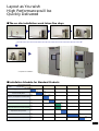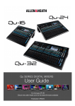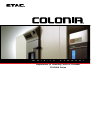
1
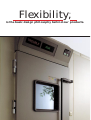
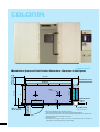
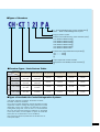
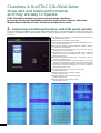
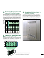
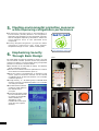
W a l k - I n
C h a m b e r
Temperature (& Humidity) Walk-In Chamber
COLONIA Series
Flexibility,
※
is the basic design philosophy behind our products.
ETAC has gained a solid reputation as a manufacturer of environmental chambers that incorporate ergonomics. Our
human approach to design can be found in the rounded corners of our original main test chambers. Now, ETAC is
ready to introduce a second generation of walk-in chambers in our COLONIA Series. These new units, known as the
"New COLONIA," will continue to offer the high degree of flexibility ※ that has been appreciated in our first
generation units. In addition, the new unit has been designed to improve and perfect its major functions through
several innovations, including the following
●using the LCD panel in the controller to enhance its monitoring capability,
●extending its temperature and humidity control ranges, and
●enlarging the effective space in the test chamber.
To raise the product assembly level at the factory prior to shipment, we have adopted a unitary design concept. This
concept has resulted in the reduction of on-site chamber installation time and the improvement of the unit's overall
quality. New COLONIA chambers include specifications that are ideal for testing finished products such as TVs,
audiovisual equipment, automotive parts, and OA equipment. As well, we have fully organized our overseas service
system to provide complete assembly, installation, and maintenance for our products in foreign countries. Choose
the unit that best suits your specific applications. COLONIA Series are available in a variety of highly original
designs, and unique features and functions.
※ Flexibility : To meet specific user needs in terms of installation, disassembly and transfer, and in obtaining optimal specifications through a broad selection of available options,
COLONIA environmental chambers are designed to be very flexible.
FRONT VIEW
500 or more
(work space)
■Installation Space and Test Chamber Dimensions Characters in the figures
W+785
W
back-side cover
3
refrigeration unit
1090
A
500 or more
(work space)
(opening and
shutting space)
W
opening width
65
D
D+130
lamp
air conditioner
▼panel
(maintenance
space)
600
control unit
□Work Space Requirement for Chamber Assembly
※The required ceiling height is the height of the chamber plus 500mm.
□The overall dimensions of the unit are determined by adding 785 mm and 130 mm to the
width and depth of the test chamber respectively.
□Installation Space
※ As shown in the figure, add the work area to the dimensions of the chamber for
maintenance, door opening/closing, and joint sealing.
■Types of Chambers
A :Air Cooled Refrigeration System Specification
None. . . Water- Cooled Refrigeration System
Program Control System
Indicates Internal Dimensions of Test Chamber (mm)
♯11: W1670×H2200×D1670
♯21: W3470×H2200×D1670
♯31: W3470×H2200×D2570
♯41: W3670×H2200×D3270
♯51: W4370×H2200×D3470
♯61: W5270×H2200×D3470
Indicates the Lowest Attainable Temperature
♯1・・・・・・−10℃
♯3・・・・・・−35℃
Only Temperature Control Chamber
Temperature and Humidity Control Chamber
■Chamber Types / Basic Feature Tables
Internal Dimensions
Specifications
(mm) W1670×H2200×D1670
W3470×H2200×D1670 W3470×H2200×D2570 W3670×H2200×D3270 W4370×H2200×D3470 W5270×H2200×D3470
Low Temperature
and Humidity Chamber
−10℃∼+80℃
15%∼95%RH
CH111P
CH111PA
CH121P
CH121PA
CH131P
CH141P
CH151P
CH161P
−35℃∼+80℃
15%∼95%RH
CH311P
CH311PA
CH321P
CH321PA
CH331P
CH341P
CH351P
CH361P
Low Temperature
Chamber
−10℃∼+80℃
CT111P
CT111PA
CT121P
CT121PA
CT131P
CT141P
CT151P
CT161P
−35℃∼+80℃
CT311P
CT311PA
CT321P
CT321PA
CT331P
CT341P
CT351P
CT361P
■Types of Available Air-Cooled Refregeration Systems
(CH111PA、CH121PA、CH311PA、CH321PA、CT111PA、
CT121PA、CT311PA、CT321PA)
Use of the air-cooled refrigeration system eliminates the work
required for condenser cooling water piping. With the air-cooled
refrigeration system, the chamber can eliminate the need for
cooling water piping work. Since the unit is so constructed that
the hot air from the heat exchanger (condenser) is discharged
to the space above, the unit requires a system to handle this
waste (such as an exhaust fan or an air-conditioner)
※The products other than those specified above can be altered to an aircooled system (Option).
4
Chambers in the ETAC COLONIA Series
stress safe and stable performance,
and they are easy to operate.
ETAC COLONIA achieves its people-oriented design objectives
by incorporating environmental protection measures and security functions.
Please note the variety of basic functions included in the unit.
1.
Improving monitoring functions with LCD panel permits.
The new controller ETACOM41 is a controller specifically designed for environmental test chambers of ETAC. This
controller is equipped with a large display screen, is easy to operate, and is capable of providing monitoring
functions.
●The settings or the execution of the program can be checked on
the graphic display screen.
●Program steps can number as many as 999.
●The program can be set to repeat as often as 9999 times, or it can
be set to repeat indefinitely.
●The controller permits the partial alteration, addition, deletion,
or skipping of program steps.
●Changing the control setting during the operation (setting
change function) is now possible.
●The controller contains an internal calendar function capable of
indicating the time of test completion (year, month, day, hour)
before the start of test.
●By selecting the program starting step, it is possible to start the
test at an intermediate step.
●To protect the test specimens in the test chamber, the controller
is equipped with an upper and lower limit setting capability that
generates an abnormal temperature alarm when the chamber
temperature exceeds the maximum or minimum allowable
temperatures set prior to test.
●Two output terminals for time signals are provided
(contact capacity 0.1A).
●Output terminals for test completion signals
(contact capacity 0.1A).
●Output terminals for external warning signals
(contact capacity 0.1A).
●Output terminals for test interlock signals
(contact capacity 0.1A).
5
Menu Screen
Program Profile Verification Screen
Program Setting Screen
Operation Screen
and
Expanding Effective Space in
2. ExtendingTemperature
4.
Humidity Control Ranges
the Test Chamber
−35℃Specification
humidity (% RH)
The temperature and humidity control ranges of the new
unit is expanded from that of the existing units so that the
lower temperature range limit can be extended to as low as
+10 ℃. This expansion of the temperature and humidity
control zone towards the lower temperature range has been
made specifically to satisfy our customers' requests, and this
has widened the applicable performance range of this new
unit.
100
95
90
80
70
60
50
The effective chamber space has been expanded by
minimizing wall protrusions, such as by incorporating the
use of the flat air conditioning unit in the space. Since these
protrusions used to inconvenience the workers when
positioning and setting test specimens, it is now possible to
make more effective use of the test chamber space.
temperature & humidity
control range
40
30
20
15
10
0
0
10
20
30
40
50
60 70
80
temperature (℃)
Temperature and
3. Improving
Humidity Uniformity
The temperature and humidity uniformity within the test
chamber has been improved by increasing the air
recirculation rate. This improvement is also applicable for
handling the heat generated from test specimens.
150
indicates the wind direction <unit m/sec.>
1.0
4.0
0.2
0.2
0.2
0.4
0.4
0.3
0.3
0.7
350
1,100
0.3
Air conditioner
0.3
These data are based on measurements made from the
vertical cross section along the centerline of the CH331P
type unit (the cross hatched section in the illustration).
6
environmental protection measures
5. Meeting
while improving refrigeration performance
●To achieve the company's goal of "The Realization of
Environmentally Friendly Products," the refrigeration
equipment and refrigeration circuits have been improved,
and the refrigerant replaced by HFC404A to achieve the
ozone depletion factor of zero (ISO14000 series
compliance).
●A newly designed refrigeration cycle permits stable
refrigeration performance even under ambient
temperatures as high as +35℃. (Water-Cooled System).
This product meets established
freon standards for cleaner air.
Security
6. Emphasizing
Through Basic Design
Photo1
By a basic design that puts an emphasis on security, the new
environmental chamber provides secure and protective
systems in its electric circuits and water piping, and provides
protection to workers in the test chamber.
●The chamber can be ventilated (air supply and exhaust)
when occupied by a worker.
●The door lock release mechanism operated from inside of
the chamber has a double feature. (photo 1)
●Since the system is equipped with an emergency stop
switch, people outside the chamber can be notified
immediately when an abnormal situation in the chamber
is detected. (photo 2)
●A large and easy - to - see warning lamp is installed above
the door so that any unexpected problem in the chamber
can readily be checked.
●Includes a double overheat
protection system based on
two different action
principles.
●A monitoring system checks
the life of the water purifier
to prevent any undesirable
effects caused by the
degradation of the
humidification water upon
other parts of the system.
(Photo 3).
Photo2
7
Photo3
Meeting Future Needs
by Advancing COLONIA
In response to the needs of society for increased measures
such as energy conservation,
COLONIA many advanced features are a step ahead.
Chamber
1. Easy-to-See
Condition Display Panel
In addition to the display of controller, a large display panel
is provided above the door to indicate chamber conditions
so that its temperature and humidity can be checked
visually when entering and leaving the chamber.
Electric Power
2. Realizing
Savings
The thorough redesign of electric circuits permits the
reduction of electric power for control to two thirds of that
required by the traditional units (our company products).
This contributes to energy conservation.
of New Packing Based on
3. Use
an Original ETAC Design for
Exterior Envelope Sealing
Traditional silicon caulking requires a long drying period.
With the use of a specially developed sealing gasket, the
exterior envelope of Colonia chambers is well sealed,
allowing for a shorter work period.
Window Comes
4. AasLarge
a Standard Item
Since the viewing window (a wiperless type) at the shoulder
height of the door is approximately 1.7 times larger than
those in traditional units, it makes the observation of
chamber interior from the outside easier. Since the window
glass surface is coated with a membrane heater, no frosting
problems occur.
8
Principle Only One
5. In
Person in the Chamber
is Permitted
Regardless of the size of the chamber, the chamber
ventilation is so designed as to permit only one working for
extended period of time.
※We can provide the ventilation system for several person if necessary.
Please do not hesitate to ask.
Rounded Corner is
6. With
Easy on People
This "kind to human" design concept employs rounded corner
wall panels, an idea that originated with our company.
These rounded corners prevent people working within or
near the chamber to feel confined or uncomfortable.
7. Grounding of Test Chamber
All panels in this unit are electrically connected via
grounding chips specially designed for COLONIA to shield
the chamber from external electrical noises and
disturbances.
9
Layout as You wish
High Performance will be
Quickly Delivered
■The on-site installation work takes five days.
Installation of floor panels
Installation of control unit
Installation of air conditioning units
Installation of wall panels
Installation of doors
Completion of installation
■Installation Schedule for Standard Products
Standard Number of Days
Items
1st
2nd
3rd
4th
5th
Carrying in the Materials
Panel Assembly Work
Machinery and Equipment Installation Work
Secondary Side Electrical Construction
Primary Side Water Piping Construction (Customer)
Primary Side Electrical Construction (Customer)
Adjustment Trial Operation
Inspection
Witness Explanation・Acceptance
10
Low
Temperature and
Humidity Chamber
CH
S P E C I F I C A T I O N S
S E R I E S
Types
Specifications
CH111P
CH111PA
CH121P
CH121PA
CH141P
CH131P
Temperature Range
−10℃∼+80℃
Humidity Range
20%∼95%RH
Temperature Heat-Up Rate
Performance
※
Temperature Dropping Rate
+20℃→−10℃
60 minutes
80 minutes
60 minutes
80 minutes
70 minutes
Temperature and Humidity Uniformity
Temperature and Humidity Variation Range
Temperature and Humidity Resolution
Sensors
Allowable Ambient Temperature
+5℃∼+35℃(+5℃∼+30℃ for Air Cooled Units)
Test Chamber Interior Dimensions (W ×H×D in mm)
1670×2200×1670
3470×2200×1670
Internal Volume (m 3)
6.1
12.7
2
Main Body
Internal Floor Area (m )
2.79
5.79
Overall Dimensions of the Unit (W × H × D in mm)
2455×2405×1800
4255×2405×1800
3470×2200×2570 3670×2200×3270
19.6
26.4
8.92
12.0
4255×2405×2700 4455×2405×3400
Door Opening Dimensions (mm)
Allowable Floor Load
Exterior Material
Interior Material
Thermal Insulation
Fans
Refrigeration Units (Hermetically Sealed Units)
Water Cooled
Air Cooled
Water Cooled
Water Cooled Air Cooled
Major Equipment
Refrigerants
Expansion Method
Thermal Heaters
Humidifier Heaters
Evaporator
Display
Power Supply
200V AC, 3 Phase, 50/60 Hz Fluctuation for Voltage Less Than ± 10%.
Required Facility
Standard Electric Current [Max. Consumption] (A)
49
Standard Electric Power (kVA)
Cooling Water (Refrigeration Ton)
Maximum Humidifier Water Flow (liters/hr)
17
1.9
−
93
56
32.2
19.4
1.9
−
3.7
2
Humidifying Water
Drain Flow
Protection Devices
Additional Functions
Communication Function
Standard Feature
11
Leakage Breaker for Power Supply, Overheat Protector Overload Relay for Refrigeration, Emergency Shut-Off Switch Microcomputer Self-Diagnosis Function, Power Failure Recovery Protection, Function, Output Function for Upper and Lower Limit Temperature, Time Signal Message Function, Pause Function, Humidifier Water Monitoring Function, Viewing Window (W 350 × H 350 mm), Room Lamps, φ54 mm Cable Port, Water Regulating Valve (except for Specification A), ※The indicated performance represents the unit performance measured during thirty minutes of stable operation without test specimens.
※Please be aware that the specification tables may be changed without notice when the units are improved or updated.
※One Refrigeration Ton =13 liters per minute
■Allowable Thermal Load Diagram
■ Allowable Thermal Load Diagram
Control Mode Operation)
36
1
C
CH
6
1
6
H1
1
36
CH
61
CH1
5
4
31
3
3
CH
1
H13
1
C
33
CH
CH
2
CH
1
4
H1
6
C
5
4
321
21
21 CH1
1
32
CH
kW
1
34
CH CH141
1
2
CH1
CH
2
1
-30
1
34
7
3
H131
331 C
*Those indicated in these diagrams are
the maximum allowable load under the
AUTO running condition.
8
34
1
7
9
H
C
H
36
1
8
CH3
1
-20
-10
0
10
20
30
40
50
60
70
80℃
-30
-20
-10
0
10
20
30
40
Room Temperature
CH161P
CH151P
50
60
70
Allowable Thermal
Load Diagram
Allowable Thermal Load Diagram
Allowable Thermal Load Diagram
9
*The allowable thermal load will vary
depending upon the ambient
temperature, cooling water temperature.
(High Humidity Operation at 90% RH)
kW
10
C
kW (Temperature
10
4
3
2
1
-30
80℃
-20
-10
0
10
20
30
40
CH311P
CH311PA
50
60
70
80℃
Room Temperature
Room Temperature
CH321PA
CH321P
CH331P
CH341P
CH351P
CH361P
70 minutes
60 minutes
70 minutes
−35℃∼+80℃
15%∼95%RH
+20℃→+80℃
60 minutes
+20℃→−30℃
60 minutes
60 minutes
80 minutes
90 minutes
110 minutes
80 minutes
±0.75℃/±5.0%RH
±0.3℃/±2.5%RH
±0.1℃/±1.0%RH
Type-T Thermocouples
+5℃∼+35℃(+5℃∼+30℃ for Air Cooled Units)
4370×2200×3470 5270×2200×3470
33.4
40.2
15.16
18.29
5155×2405×3600 6055×2405×3600
1670×2200×1670
3470×2200×1670
6.1
12.7
2.79
5.79
2455×2405×1800
4255×2405×1800
3470×2200×2570 3670×2200×3270 4370×2200×3470 5270×2200×3470
19.6
26.4
33.4
40.2
8.92
12.0
15.16
18.29
4255×2405×2700 4455×2405×3400 5155×2405×3600 6055×2405×3600
Single Swing Door W 850 × H 1820
600 kg/m2 (Surface Load)
PVC Coated Steel Plate
Stainless Steel Plate SUS304 2B Finish
Rigid Expanded Polyurethane Board (Thickness 65mm)
Sirocco Fan
Water Cooled
Water Cooled
Air Cooled
Water Cooled
Air Cooled
Water Cooled
HFC404A
Pulse Control Electronic Expansion Valve + Automatic Expansion Valve
Ni-Cr Strip Heaters
Sheathed Heaters
Plate Fin Coils
LCD Display by Graphic Matrix
200V AC, 3 Phase, 50/60 Hz Fluctuation for Voltage Less Than ± 10%.
56
108
19.4
37.4
3.7
7.4
4
−
3.7
2
−
63
108
123
21.8
37.4
42.6
5.5
7.4
11.1
4
Tap Water
Natural Drain (Open to atmosphere) 20A
(Double Protection), Overheat Protector for Boil-Dry, High and Low Pressure Limit Switch, Overload Relay for Fan Switch,
Circuit Breaker for Thermal Heater, Circuit Breaker for Humidifier Heater, Circuit Breaker for Control Circuit,
and Emergency Escape Mechanism
Keeping Function Prevention with Instant Power Failure, Test Specimen and Power Supply Interlock Function, External Alarm Output
Output Terminals, Time Up Signal Output Terminal, Calendar Timer Function, Wait Function, Memory Backup Function, User
Test Chamber Temperature and Humidity Display Function, "RUN" Display Function, "TROUBLE" Display Function.
GP-IB, RS232C or RS422A (Option).
Ventilation Fan(for air supply and exhaust), Refrigeration Pressure Gauges, Water Purifier, Wick (for Wet-Bulb Temperature Sensor),
User's Manual, Inspection Certificate (with performance data), Warranty Document.
12
Low Temperature
Chamber
CT
S P E C I F I C A T I O N S
S E R I E S
Types
Specifications
CT111PA
CT111P
CT121P
CT121PA
Temperature Range
CT141P
CT131P
−10℃∼+80℃
Humidity Range
Rerformance
※
Temperature Heat-Up Rate
+20℃→−10℃
60 minutes
80 minutes
60 minutes
80 minutes
70 minutes
Temperature and Humidity Uniformity
Temperature and Humidity Variation Range
Temperature and Humidity Resolution
Sensors
Allowable Ambient Temperature
+5℃∼+35℃(+5℃∼+30℃ for Air Cooled Units) Test Chamber Interior Dimensions (W ×H×D in mm)
1670×2200×1670
3470×2200×1670
Internal Volume (m 3)
6.1
12.7
2
Main Body
Internal Floor Area (m )
2.79
5.79
Overall Dimensions of the Unit (W × H × D in mm)
2455×2405×1800
4255×2405×1800
3470×2200×2570 3670×2200×3270
19.6
26.4
8.92
12.0
4255×2405×2700 4455×2405×3400
Door Opening Dimensions (mm)
Allowable Floor Load
Exterior Material
Interior Material
Thermal Insulation
Fans
Major Equipment
Refrigeration Units (Hermetically Sealed Units)
Water Cooled
Air Cooled
Water Cooled
Water Cooled
Air Cooled
Refrigerants
Expansion Method
Thermal Heaters
Evaporator
Display
Required Facility
Power Supply
200V AC, 3 Phase, 50/60 Hz Fluctuation for Voltage Less Than ± 10%.
Standard Electric Current [Max. Comsumption] (A)
31
Standard Electric Power (kVA)
Cooling Water (Refrigeration Ton)
10.7
1.9
−
59
38
20.4
13.2
1.9
−
3.7
Drain Flow
Protection Devices
Additional Functions
Leakage Breaker for Power Supply, Overheat Protector (Double Protection), Overload Relay for Refrigeration, Emergency Shut-off Switch, Microcomputer Self-Diagnosis Functions, Power Failure Recovery Protection, External Alarm Output Function, Upper Calendar Timer Function, Wait Function, Memory Backup Function, Communication Function
Standard Feature
13
Viewing Window (W350 × H350 mm), Refrigeration Pressure Gauges, Water Regulating Valve ※The indicated performance represents the unit performance measured during thirty minutes of stable operation without test specimens.
※Please be aware that the specification tables may be changed without notice when the units are improved or updated.
※One Refrigeration Ton =13 liters per minute
■Allowable Thermal Load Diagram
(Temperature Control Mode Operation)
kW
8
7
6
1
14
CT
5
41
CT1
4
3
21
CT1
2
10
9
8
1
34
7
CT
T341
6
C
5
4
321
CT
3
9
*Those indicated in these diagrams are
the maximum allowable load under the
AUTO running condition.
1
36
8
CT
7
6
361
CT
5
331
CT
1
33
31
CT3
CT
3
2
1
10
4
CT321
1
CT12
*The allowable thermal load will vary
depending upon the ambient
temperature, cooling water temperature.
11
36
1
Allowable Thermal Load Diagram
Allowable Thermal Load Diagram
9
Allowable Thermal Load Diagram
kW
10
CT
kW
2
1
1
-30
-20
-10
0
10
20
30
40
50
60
70
80℃
-30
-20
-10
0
10
20
30
40
Room Temperature
50
60
70
80℃
Room Temperature
-30
-20
-10
0
10
20
30
40
50
60
70
80℃
Room Temperature
CT151P
CT161P
CT311P
CT311PA
CT321P
CT321PA
CT331P
CT341P
CT351P
CT361P
70 minutes
60 minutes
70 minutes
−35℃∼+80℃
+20℃→+80℃
60 minutes
+20℃→−30℃
60 minutes
60 minutes
80 minutes
90 minutes
110 minutes
80 minutes
±0.75℃
±0.3℃
±0.1℃
Type-T Thermocouples
+5℃∼+35℃(+5℃∼+30℃ for Air Cooled Units)
4370×2200×3470 5270×2200×3470
33.4
40.2
15.16
18.29
5155×2405×3600 6055×2405×3600
1670×2200×1670
3470×2200×1670
6.1
12.7
2.79
5.79
2455×2405×1800
4255×2405×1800
3470×2200×2570 3670×2200×3270 4370×2200×3470 5270×2200×3470
19.6
26.4
33.4
40.2
8.92
12.0
15.16
18.29
4255×2405×2700 4455×2405×3400 5155×2405×3600 6055×2405×3600
Single Swing Door W850×H1820
600kg/m2(Surface Load)
PVC Coated Steel Plate
Stainless Steel Plate SUS304 2B Finish
Rigid Expanded Polyurethane Board (Thickness 65mm)
Sirocco Fan
Water Cooled
Air Cooled
Water Cooled
Water Cooled
Air Cooled
HFC404A
Pulse Control Electronic Expansion Valve + Automatic Expansion Valve
Ni-Cr Strip Heaters
Plate Fin Coils
LCD Display by Graphic Matrix
200V AC, 3 Phase, 50/60 Hz Fluctuation for Voltage Less Than ± 10%.
74
38
25.8
7.4
13.2
3.7
−
3.7
−
46
74
89
15.9
25.6
30.8
5.5
7.4
11.1
Natural Drain (Open to atmosphere) 20A
High and Low Pressure Limit Switch, Overload Relay for Fan Switch,
Circuit Breaker for Thermal Heater, Circuit Breaker for Control Circuit.
and Emergency Escape Mechanism
Keeping Function Prevention with Instant Power Failure, Test Specimen and Power Supply Interlock Function,
and Lower Temperature Output Function, Time Signal Output Terminals, Time Up Signal Output Terminal,
User Message Function, Pause Function, Test Chamber Temperature Display Function, "RUN" Display Function, "TROUBLE" Display Function.
GP-IB, RS232C or RS422A (Option).
Room Lamps, φ54mm Cable Port, Ventilation Fan (for air supply and exhaust),
(except for Specification A), User's Manual, Inspection Certificate (with performance data), Warranty Document.
14
Hinged Double Door
Hinged Single Door
Effective Opening Dimensions:
W1400 × H1820 mm
Effective Opening Dimensions:
W850 × H1820mm
User Option List
Abundant Options to
Meet a Variety of Customer
Needs.
Large Door
Hinged Double door with an
opening of W2000 × H2000 mm.
This door is most suitable when
handling large products or test
specimens that are brought in on
the rack for environmental testing.
expansion
valve
Cable Port
Operation Slot
This panel is needed to prevent rut
marks on the floor surface when
castered dollies are used to move test
specimens into the test chamber. Since
the standard floor surface loading is 600
kg/m2 of the floor area, this reinforcing
panel is needed only when the floor
loading exceeds 600 kg/m2.
※When the floor reinforcing panel is
used, the standard time required for
heating and cooling will be altered.
The measurement port of the
standard inner φ54 mm or 120 mm
is available. (The location of the port
will be determined with the consent
of the customers)
The inner diameter of this port is
150mm. The port is used to insert or
extract the specimens from outside
of the test chamber. Use this slot in
conjunction with the viewing
window.
Flashing Warning Light
Sloped Stepping Plate
Viewing Window
Defrost Circuit
vaporizer
Stainless Steel Plate for
Reinforcement of Interior Bottom
(containing an anti-freezing heating element)
dryer
intake air pressure
adjustable valve
hot gas device
solenoid valve
cooling Water
capacitor
accumulator
compressor
This is a defrost circuit for the hot
gas defrost method. Use this circuit
when test specimens are frequently
taken in and out of the low
temperature test chamber.
This hot wire imbedded glass
window has the dimensions of W600
× H400 mm. The window is best
suited for monitoring and studying
the interior of the test chamber.
Vinyl Curtain
Additional Cooling System
for Specimens Load
This curtain is used to minimize
fluctuations in the test chamber
environment when its door is
opened and closed frequently.
15
Use this system when the heat
generated by the test specimens
exceeds the standard allowable
thermal load.
This light will be lit whenever an
abnormality occurs in the chamber
operation. The blinking signals are
generated by the rotation of the
lamp at a rate of 170 times/minute,
and the signals can be visible from
a distance.
Air cooled refrigerator
specification
Use the air cooled hermetically
sealed refrigeration system for
chamber cooling when cooling
water piping (for condenser) cannot
be installed due to building
construction complications or due to
chamber location.
This plate is made of 6mm thick
aluminum plate, and is available
either in the one-side-openable type
or the two-side-openable type.
Indicator Lights Face Plate
This plate display panel is used to
indicate the chamber's operating
conditions and equipment names.
The signs are either printed or
engraved. The standard sign is
"RUN."
Indoor Fluorescent Lamps
Plug Socket
The specification of this moisture
resistant fluorescent lamp is 40W ×
2 bulbs × one set/3.3 m2.
The allowable temperature range
for these lamps is +5℃∼+40℃/
95%RH.
Humidity-proof electric outlets with
grounding, 100V/20A∼200V/20A,
have been provided. And, it is also
possible to attach an interlock circuit.
Relative Humidity
Output System
Recorder
The recording chart width is 100
mm, and its scale is from −50℃ to
+100℃. This is a small two-point
and hybrid recorder. The unit is also
available for the direct analog
output of humidity with its
corresponding recorder.
Low Temperature and
Low Humidity Specification
This is an analog output unit
capable of printing the relative
humidity (%RH) directly over the
recording chart.
The −40℃ Specification
Interphone
Interphone is available for
communication between the inside
and outside of the test chamber.
The allowable temperature is up to
+40℃.
Smoke Detector
A smoke detector is installed within
the control unit to detect smoke
resulting from abnormal heat
generation.
RS232C Interface
GP-IB Interface
This is an interface compatible with
the RS232C standard. When this
interface is used for controlling a
group of RS232C's, the interface
after the second unit will become
RS422A. This system is very
effective in the centralized control of
several environmental chambers.
This interface is compatible with the
IEEE-488 standard. The GP-IB card
is installed within the ETACOM and
its connector terminal is located on
the front face of the chamber for
easy access (a GP-IB cable of 2m
length is attached).
Ceiling Air Discharge
Specification
Preparation Room
dehumidifier
air exhaust heat
(honeycomb rotor)
O.A.
heater
test chamber
WET AIR
1980
FAN
DRY AIR
treated air
FAN
Preparation
room
test chamber
With this specification, the unit will
be equipped with a highly durable
dry-type dehumidifier so that it is
possible to reproduce an accurate
low temperature and low humidity
environment (as low as +5℃
/10%RH)
With this specification, a second
stage refrigeration system is added
so that the chamber can run
continuously with its temperature as
low as −40℃.
No-Floor-Panel Specification
The preparation room helps to
maintain the stability of the test
chamber temperature (humidity) when
the door is opened or closed. By
specifying the temperature control
option for the foyer, this space can be
used to acclimatize the worker prior to
entering the very high or low
temperature test chamber for
inspection or measurement.
With this specification, the supply
air will be discharged uniformly
across the entire ceiling surface to
create an uniform downward air flow
pattern in the chamber.
●AUTO START/AUTO STOP function
With this command, the starting and completion time of the test
chamber operation can be set at any desired value.
●Automatic Power Failure Recovery Function
With this command, the chamber can automatically resume its
operation from the condition prior to the power outage. This is
possible without activating the START key when the power is
restored after outage (the response time for this command has
been factory set at 5 minutes).
The no-floor-panel Specification is used in the CT series chambers. This
type of floor is suitable for heavy test specimens that can be carried onto the
concrete floor directly. Use this type of floor in the temperature range of +
5℃∼+50℃.
●Additional Overheat Protector
Although the standard chamber is equipped with three overheat
protectors, this option can provide an additional overheat protection for
test specimens.
●Overcooling Protector
This command provides an option to prevent the chamber temperature
from going below the set limit.
16
Option Table
ETAC Watching System
(Central Control and Monitoring
/Automated Instrumentation System)
C-BUS, Central Control
and Monitoring System
Types
Option Names
CT
Hinged Double Door
●
●
Hinged Single Door
●
●
Large Door
●
●
Stainless Steel Plate for
Reinforcement of Interior Bottom
●
●
Sloaped Stepping Plate
●
●
Vinyl Curtain
●
●
Cable Port (φ54 mm)
●
●
Cable Port (φ128 mm)
●
●
Flashing Warning Light
●
●
Plug Socket (100V/15A)
●
●
Plug Socket (200V/20A)
●
●
Indoor Fluorescent Lamps
●
●
Interphone
●
●
Large Viewing Window
(with the imbedded frost prevention heating wire)
●
●
Smoke Detector
●
●
Indicator Light Face Panel
●
●
Defrost Circuit
●
●
Total Ceiling Surface Air Diffuser System Specification
●
●
No Floor Panel Specification
×
●
Preparation Room
●
●
Additional Cooling System
●
●
Air-Cooled Refrigeration System Specification
●
●
The −40℃ Specification
●
●
Low Temperature and Low Humidity
Specification
●
×
Recorder
●
●
●
●
GP−IB Interface
●
●
AUTO START/AUTO STOP Function
●
●
RS232C Interface
17
Automatic Power Failure Recovery Function
●
●
Additional Overheat Protector
●
●
Overcooling Protector
●
●
C−BUS permits the checking and
monitoring of the running conditions of environmental
testers through a personal computer. As long as the
environmental tester is equipped with a communication
interface (RS232C), which is the case for HIFLEX series
testers and others, the C−BUS enables that computer to set
up the test conditions, monitor the test in progress, verify
the test completion time, and assess problems if there are
any.
First chamber
second chamber
third chamber
20th chamber
RS232C
RS232C/
RS422A
or modem
Computer
Protocol converter
●To connect more than two environmental test chambers
Automated
Instrumentation
System
In addition to C−BUS, the system is equipped with AUTEST,
which is capable of automatically controlling the voltage
applied to the test specimens by making it synchronous with
the environmental test conditions. AUTEST permits the real
time display of test conditions, specimen temperatures, as
well as the voltage data at the specified measurement
locations by converting these data into a digital form via A/D
converter. These digitized data can also be stored for other
uses. By having the standard characteristic data of the test
specimens input and stored in its memory prior to the test,
AUTEST can identify and reject the defective specimens in its
data processing stage if any one of these data during the test
exceeds the allowable limit. One "Watching Unit" is installed
on each environmental chamber. For a multiple chamber
system, information from each chamber is integrated into
the personal computer through the protocol converter for
the management and analysis of the measured data.
watching unit
function board
Power supply
Walk in Chamber
COLONIA
power supply
control board
controller
temperature
voltage
electric
current
electric
resistance
specimen
board for measuring
temperature
board for measuring
voltage
board for measuring
current
board for measuring
resistance
RS232C
System structure
M oth er Boa rd
CH
RS232C
/RS422A
or modem
personal computer
Construction Work for Connecting to the Primary Side
55
0
0
53
Primary Power Supply
Cable Opening
RS
T
φ51
E
Terminal Block
3φ AC200V
Refrigerator Unit
Control Panel
of Floor
Surface
A Leveling
Prepare the floor surface to be
as flat and horizontal as
possible. Also secure the space
needed to store parts and
equipment for installing the
test chamber. An area twice as
large as the installed space of
the chamber must be made
available.
B Electric Construction
Connect the power cables
securely at the terminal block of
the chamber through its cable
port of 50 mm diameter. The
allowable voltage fluctuation of
the power supply is ±10%, and
the noise level should be less
than 1.5 kV for 1 microsecond or
higher. Make sure that the power
supply is firmly grounded.
Inlet
PT 1 1/
4
Outlet
PT 1 1/
4
Inlet
PT 1/
2
290
Drain from the Inside
Bottom of Chamber
Polyvinyl Chloride
Pipe 20A
Refrigerator
Unit
Refrigerator
Unit
110
Refrigerator
Unit
740
1070
85
1070
Refrigerator
Unit
Drain from Humidifying
Water Circuit
Polyvinyl Chloride
Pipe 20A
490
70
250
FL
FL
Water
Construction
C Cooling
Complete the cooling water
work by using specified piping
materials (equivalent of SGP).
The pipe diameter is PT11/4B.
Make sure that the water flow
rate satisfies the specified value
(see the table below).
Water
Construction
D Humidifier
Connect the water line whose
quality is better than ordinary
tap water and whose pressure is
between 2.0 -7.0 kg.
(CH Type)
165
FL
FL
Connection
Construction1
E Drain
Drainage from air-conditioner.
The diameter of the drain pipe
is PT3/4B.
Connection
Construction2
F Drain
Drainage from the inside
bottom of chambers.
The drain pipe diameter is
3/4B.
The drain outlet should be
open to the atmosphere.
■Maximum Power Consumption (In case of 200VAC, 3phase)
111P 111PA 121P 121PA 131P
141P
(49)
Electric Power(kVA)
17
19.4
Current Rating(A)
(31)
(38)
(59)
(38)
Electric Power(kVA)
10.7
13.2
20.4
13.2
CH
CT
(56) (93)
151P 161P 311P 311PA 321P 321PA 331P
Current Rating(A)
32.2
(108)
(56)
37.4
19.4
341P
351P
(63)(108)
21.8
37.4
361P
(123)
42.6
(46) (74)
(89)
15.9
25.6
30.8
5.5
7.4
11.1
■Cooling Water for Refrigerator Unit ※1RT =13 liters/minute
Total Flow Rate (RT)
2
Friction Loss (kg/cm G)
1.9
−
1.9
−
3.7
0.7
−
0.7
−
0.7
7.4
3.7
0.7
−
3.7
−
−
0.7
−
0.7
■Humidifier Water Flow (liters/hr)
Only for the CH type
2.0
4.0
2.0
4.0
18
ETAC creates IA ( Inspect Automation).
KUSUMOTO CHEMICALS LTD. / ETAC Division
Kusumoto No.1 Building 1-11-13 Uchikanda, Chiyoda-ku Tokyo, 101 JAPAN
TEL 81-3-3295-8681 FAX 81-3-3233-0217
This clover logo represents our reliable services
Promptness and accuracy are our company's first priority.
For further inquiries, contact:
Notice for safe use
When using, please read attached manual
carefully. Avoid installing in places where water,
moisture, dust, or soot may gather. These may
cause fire, accident, or electric shock.
9709-MP-10000