1
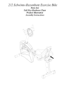
USER MANUAL – EN IN 8727 Spinning Bike inSPORTline Atana 1 CONTENTS SAFETY INSTRUCTIONS .................................................................................................................................... 3 IMPORTANT NOTES ........................................................................................................................................... 3 EXPLODED DRAWING ....................................................................................................................................... 4 PARTS LIST ........................................................................................................................................................... 4 CHECK LIST .......................................................................................................................................................... 8 ASSEMBLY INSTRUCTIONS .............................................................................................................................. 9 SM7224-64 INSTRUCTION MANUAL .............................................................................................................. 15 2 SAFETY INSTRUCTIONS To ensure the best safety of the exerciser, regularly check it on damages and worn parts. If you pass on this exerciser to another person or if you allow another person to use it, make sure that that person is familiar with the content and instructions in these instructions. Only one person should use the exerciser at a time. Before the first use and regularly make sure that all screws, bolts and other joints are properly tightened and firmly seated. Before you start your work-out, remove all sharp-edged objects around the exerciser. Only use the exercise for your work-out if it works flawlessly. Any broken, worn or defective part must immediately be replaced and/or the exerciser must no longer be used until it has been properly maintained and repaired. Parents and other supervisory persons should be aware of their responsibility, due to situations which may arise for which the exerciser has not been designed and which may occur due to children’s natural play instinct and interest in experimenting. If you do allow children to use this exerciser, be sure to take into consideration and assess their mental and physical condition and development, and above all their temperament. Children should use the exerciser only under adult supervision and be instructed on the correct and proper use of the exerciser. The exerciser is not a toy. Make sure there is sufficient free space around the exerciser when you set it up. To avoid possible accidents, do not allow children to approach the exerciser without supervision, since they may use it in a way for which it is not intended due to their natural play instinct and interest in experimenting. Please note that an improper and excessive work-out may be harmful to your health. Please note that levers and other adjustment mechanisms are not projecting into the area of movement during the work-out. When setting up the exerciser, please make sure that the exerciser is standing in a stable way and that any possible unevenness of the floor is evened out. Always wear appropriate clothing and shoes which are suitable for your work-out on the exerciser. The clothes must be designed in a way so that they will not get caught in any part of the exerciser during the work-out due to their form (for example, length). Be sure to wear appropriate shoes which are suitable for the work-out, firmly support the feet and which are provided with a non-slip sole. Be sure to consult a physician before you start any exercise program. He may give you proper hints and advice with respect to the individual intensity of stress for you as well as to your work-out and sensible eating habits. IMPORTANT NOTES Assemble the exerciser as per assembly instructions and be sure to only use the structural parts provided with the exerciser and designed for it. Prior to the assembly, make sure the contents of the delivery is complete by referring to the parts list of the assembly and operating instructions. Be sure to set up the exerciser in a dry and even place and always protect it from humidity. If you wish to protect the place particularly against pressure points, contamination, etc., it is recommended to put a suitable, non-slip mat under the exerciser. 3 The general rule is that exercisers and training devices are no toys. Therefore, they must only be used by properly informed or instructed persons. Stop your work-out immediately in case of dizziness, nausea, chest pain or any other physical symptoms. In case of doubt, consult your physician immediately. Children, disabled and handicapped persons should use the exercise only under supervision and in presence of another person who may give support and useful instructions. Be sure that your body parts and those of other persons are never close to any moving parts of the exerciser during its use. When adjusting the adjustable parts, make sure they are adjusted properly and note the marked, maximum adjusting position, for example of the saddle support, respectively. Do not work out immediately after meals! EXPLODED DRAWING 84 85 13 14 83 9 97 63 41 25R 7 82 86 42 12 83 88 89 79 16 19 20 21 22 33R 10 24R 11 28 29 12 23R 27 90 87 18 33L 37 36 26 30 31 32 35 34 1 8 66 67 68 74 72 65 73 69 53 71 92 93 94 88 17 15 4L 2 4R 78 80 30 81 53 23L 24L 76 57 26 27 57 91 77 44 25L 51 52 7 6 5 47 48 5 6 95 38 5 6 7 75 53 50 49 56 57 59 64 60 62 96 64 98 99 100 101 102103 104 105 45 39 40 61 63 3 46 PARTS LIST Part No. Description Qty 1 Main frame 1 2 Front stabilizer 1 3 Rear stabilizer 1 4L Left triangle cap 2 4R Right triangle cap 2 4 43 5 Allen bolt M8x1.25x20L 12 6 Spring washer D15.4xD8.2x2T 12 7 Flat washer D16xD8.5x1.2T 12 8 Front post 1 9 Seat post 1 10 Seat 1 11 Seat adjustable tube 1 12 L knob 25L 2 13 Handlebar 1 14 Computer fixing plate 1 15 D plug 1 16 Cover of front post 1 17 Protective cover 1 18 Inner insert 1 19 Stop plate(1) 2 20 Spring 2 21 Stop plate(2) 2 22 L knob 50L 2 23L Left chain cover 1 23R Right chain cover 1 24L Left crank 1 24R Right crank 1 Pedal 1 26 Hex bolt 2 27 Bolt cover 2 28 Allen screw M10*1.5*20L 5 29 Hex nut M10*1.5*8T 5 30 Round cross bolt M5x0.8x15L 4 31 Pin D6*26.5*7.7 1 32 Cross screw ST4.2*1.4*20L 9 33L Left cover of brake 1 33R Right cover of brake 1 34 Brake handlebar 1 35 Belt 1 36 Pulley 1 37 BB sets 1 38 Flat washer D25*D8.5*2T 2 39 Outer flywheel 1 25L/R 5 40 Inner flywheel 1 41 Cable plug 2 42 Swing connection fixing bracket 1 43 Protecting ring 1 44 Allen screw M6*1*15L,8.8级 6 45 Tension cable 1 46 Lower tension cable 1 47 Magnet fixing bracket 1 48 Magnet 8 49 Magnet fixing plate 1 50 Axle of magnet fixing bracket 1 51 Spring D1.2*55L 1 52 Flat washer D18*D8.5*1.0T 1 53 Nylon nut M8*1.25*8T 5 56 Magnet cell 6 57 Cross bolt M5*0.8*10L 4 59 Adjustable round wheel 4 60 Allen bolt M8*1.25*40L 2 61 Round moving wheel 2 62 Bushing 4 63 Nylon nut 3 64 Screw ST4*1.41*12L 10 65 Idle wheel fixing plate 1 66 Carriage bolt M8*1.25*20L 3 67 Adjustable bolt 1 68 Hex nut M6*1*5T 1 69 Bearing 2 71 Flat washer D18*D8.5*1.2T 2 72 C ring S-17(1T) 2 73 Curved washer D17*D22*0.3T 1 74 Hex nut M8*1.25*6T 1 75 Allen screw M8*1.25*16L 4 76 spring D1.4*55L 1 77 Fixing plate of brake strap 1 78 Hex boltM8*52L 1 80 Brake plate 1 81 Cow leather 1 82 Allen bolt M8x1.25x45L 1 6 83 Square plug 38x38x18L 3 84 Cross bolt M5*0.8*10L 4 85 Computer 1 86 Round-head screw M5*0.8*15L 2 87 Nylon nut M6*1.0*6T 1 88 Allen screw M6*1*15L 2 89 Tension fixing plate 1 90 Screw ST4.2*1.4*15L 4 91 Fixing plate (1) 1 92 Buffer D10*5.5T 2 93 Hex bolt M5*0.8*10L, 2 94 Flat washer D15*D5.2*1.0T 2 95 Fixing plate (2) 1 96 Round magnet 1 97 Cross bolt M5*10L 1 98 Sensor bracket 1 99 Sensor cable 1 100 Adaptor 1 101 Electric cable 1 102 Cable buckle 1 103 Cross screw ST4.2x1.4x12L 4 104 Motor 1 105 Upper computer cable 1 7 CHECK LIST 1 2 x1 3 x1 13 x1 x1 14 x1 x2 x1 x1 5 M8*1.25*20L x8 6 D15.4*D8.2*2T x8 7 x1 x1 D16*D8.5*1.2T x8 M5*0.8*15L x2 x1 M5*10L x1 15 13 x1 8 x1 ASSEMBLY INSTRUCTIONS STEP 1 5 6 M8*1.25*20L 7 D16*D8.5*1.2T D15.4*D8.2*2T (x8) (x8) (x8) 59 5 6 7 2 1 5 6 7 3 Step-1 1) Assemble the front stabilizer (2) and rear stabilizer (3) onto the main frame (1) by using the flat washer (7), spring washer (6), and allen bolt (5). 2) Adjust the proper height by turning the adjustable round wheel (59). 9 STEP 2 8 UP 9 UP DOWN 8 DOWN 9 22 22 Step-2 Handlebar post (8) and seat post (9) has been preassembled, you can adjust them stepless up and down by knob (22). 10 STEP 3 97 M5*10L (x1) 8 13 13 12 8 9 9 Step-3 1) Assemble the handlebar (13) onto the handlebar post (8) by knob (12) 2) Assemble the seat (10) onto the seat post (9) by knob (12), cross screw (97). 11 STEP 4 14 a c b d 84 M5*1.0*10L(x4) 86 M5*1.0*15L (x2) Step-4 1) Assemble the computer fixing plate (14) onto handlebar post (8) by using round-head screw (86) as the fig a shown. 2) Pass the upper computer cable (105) through the hole of computer fixing plate (14) as the fig b shown. 3) Insert the cable plug (41) as the fig c shown. 4) Assemble the computer (85) onto the computer fixing plate (14) by cross bolt (84) as the fig d shown. 12 STEP 5 15 13 100 Step-5 1) Assemble the left pedal (25L) onto left crank by anti-clockwise, and assemble the right pedal (25R) onto right crank by clockwise. 2) Plug the adaptor (100) and turn on the computer. 13 STEP 6 You can move the machine easily like the fig. 14 SM7224-64 INSTRUCTION MANUAL DISPLAY FUNCTIONS ITEM TIME SPEED DISTANCE CALORIES PULSE RPM WATT DESCRIPTION Setting range 0:00~99:00; Display range 0:00 ~ 99:59 Display range 0.0 ~ 99.9 Setting range 0.00~99.90KM; Display range 0.0 ~ 99.99 Setting range 0~9990; Display range 0 ~ 9999 Setting range 0-30~230; Display range P-30~230 Display range 0 ~ 999 Setting range 10~350; Display range 0~999. KEY FUNCTION ITEM DESCRIPTION Recovery Test heart rate recovery status. Hold on pressing for 2 seconds, computer will reboot and start from user setting. Reset Reverse to main menu during presetting workout value or stop mode. Down To select training mode and adjust function value down. Up To select training mode and adjust function value up Start/ Stop Start or Stop workout. 15 Mode Confirm/Enter setting or selection. OPERATION PROCEDURE POWER ON When POWER ON, buzzer will sound 1s and LCD full display for 2 seconds (Picture1). Then display wheel diameter and unit (Picture2). Then go to Standby mode (Picture 3). Picture 1 Picture 2 Picture 3 WORKOUT MODE SELECTION User can press UP and DOWN to select: Manual Program User Target H.R.C, then press MODE to enter. MANUAL MODE When select Manual mode, user can press START/STOP to start workout. Then TIME begins to count up and RPM/SPEED/DISTANCE/CALORIES/WATT display the exercise value (Picture 4 & 5). If user input WATT Target, user can adjust the WATT target during exercise, and the load level will automatically adjust per the preset WATTS value and current RPM. If user does not input WATT Target, user can adjust the load level during work out (Picture 6). Picture 4 Picture 5 16 Picture 6 PROGRAM MODE Entering PROGRAM mode, LCD display as Picture 7. User can press UP or DOWN key to select program with 12 profiles from P1 to P12. After selecting the program, PX (X=1, 2, 3.....12) will display in 2s. Press START/STOP to start workout. Load level also can be adjusted during exercise. Picture 7 USER MODE When select USER mode, LCD will show as Picture 8. User can press UP or DOWN to adjust LOAD level and confirm by MODE key. Then set TIME, hold MODE for 2s to confirm setting. Press START/STOP to start workout. Picture 8 17 TARGET H.R.C. MODE Before exercise in Target H.R.C. mode, user can press UP or DOWN to set up AGE (Picture 9) and confirm by MODE key. Then press UP or DOWN to select H.R.C: 55%, 75%, 90% or TAG, system will calculate pulse value accordingly and display on PULSE window (Picture 10). Picture 9 Picture 10 RECOVERY During exercise, when there is pulse detected, press RECOVERY key. Then all function display will stop except TIME starts counting down from 00:60 to 00:00 (Picture 11). Screen will display your heart rate recovery status with F1, F2….to F6 (Picture 12). F1 is the best, F6 is the worst. User may keep exercising to improve the heart rate recovery status. (Press the RECOVERY button again to return the main display.) Picture 11 Picture 12 18 REMARK: When console acts abnormal, please plug out the adaptor and plug in again. SEVEN SPORT, s.r.o. Borivojova 35/878 130 00 Praha 3, Czech Rebublic CRN: 268 47 264, VAT ID: CZ26847264 Orders: +420 556 300 970, [email protected] Warranty Claims: +420 556 770 190, Mobile: +420 604 853 019, [email protected] Service: +420 556 770 190, Mobile: +420 604 853 019, [email protected] Fax: +420 556 770 192, (Service +420 556 770 191) Web: www.insportline.cz, www.worker.cz, www.worker-moto.cz INSPORTLINE, s.r.o. Bratislavska 36, 911 05 Trencin, Slovakia CRN: 36311723, VAT ID: SK2020177082 Orders: +421(0)326 526 701, +421(0)917 649 192, [email protected] Warranty Claims: +421(0)326 526 701, +421(0)918 408 519, [email protected] Fax: +421(0)326 526 705 Web: www.insportline.sk, www.worker.sk, www.worker-moto.sk Date of Sale: Stamp and Signature of Seller: 19