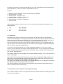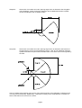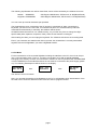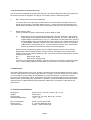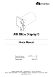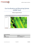
1
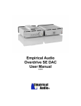
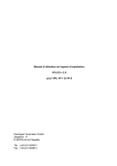
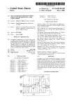
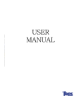
User-manual for the GPS-flightrecorder VP 8 from Peschges Variometer GmbH
Version 2.0
1. Overview
1
2. Modes of operation
2
2.1 Recordingmode
2.1.1 Startphase
2.1.2 Automatic sector-recognition and taskpointswitching
2.1.3 Automatic reset of the data-memory
2.1.4 Maunually clearing of the data-memory
2.1.5 Startform (Optional)
2
3
3
5
5
6
2.2 PC-Mode
7
3. Mounting / installation / maintenance
8
3.1 Mounting
8
3.2 Installation
3.2.1 Connection to the power-supply
3.2.2 Connection to a motorcontrol-unit
8
8
9
3.3 Maintenance
9
4. Technical specifications
9
1. Overview
The GPS-flightrecorder VP 8 from Peschges Variometer GmbH is a standalone device, that is
intended to record GPS-positiondata. In addition to the positiondata, the height calculated from the air
pressure by using the ICAO-standard-atmosphere is recorded, too. A precision pressure altitude
sensor, that is temperature-compensated across the complete temperature range is used for that
purpose.
The device is constructed to be mounted onto the cameraholder in the glider. For that purpose, a
camerascrew-holder is inserted into the bottom of the unit.
For information of the user and for displaying different modes of operation, a LC-display is used. A
push-button beside the display allows the direct control of the device in the different modes.
Additionally, a connector for the external power supply and a connector for the data-transmission to a
PC are placed on the backside.
No internal power-supply is included in the VP 8! So, the user has to ensure a good power-supply
from an external battery, which should only be used for the VP 8.
page 1
2. Modes of operation
The flightrecorder can be operated in 2 modes. The first mode is the recordingmode which is normally
used during the flight, the 2nd mode is the PC-mode, which is used for data-transmission.
2.1 Recordingmode
If the unit is switched on by applying an external 12V DC-voltage and the device is not connected to a
PC, it starts in the normal recordingmode. The LC-display shows the following startsequence:
PESCHGES
VP8 v2.x
2 sec.
Ser.-Nr.
xxxxxxxx
3 sec.
and after that, the VP 8 switches to the normal operationscreen
Startform
OK!xxxxx
1 sec.
GPS-Init
1-7 sec.
dddxxccc
NAMEyzzm
You can see the following values on the display:
ddd
- Distance to the next taskpoint:
Display of the distance from the last valid GPSposition to the next point of the flighttask in km,
if the distance is > 1000 km, 999 is displayed.
xx
- operationstatus of GPS-receive:
ok no -
Recording of a valid GPS-position in the last
recording-interval
No recording of a valid GPS-position
possible during the last recording-interval
ccc
- Course to the next taskpoint
Display of the course from the last valid GPSposition to the next turnpoint of the flighttask in
degree (0 - 359).
y
- Shows, that an Event-Marker has been recorded (* for 3 sec.)
zz
- Remaining recording-time in hours, i.e. 15 means >= 15 hours remaining time
ST stands for waiting for the takeoff
-- means, that no memory is left for recording flightdata
m
- Indicator for motor-activity (*)
With the push-button, an additional GPS-position and pressure-altitude can be recorded, a so called
"event-marker". This can be used to mark a special position, i.e. the rounding of a turnpoint. The
"event-marker"-recording only works if the GPS-receive is OK.
If the VP 8 is switched off and back on during the normal recording, the data recorded before are
retained. The unit switches immediately into the recording-mode without waiting for a start or to allow
page 2
the editing of the startform. During the data-transfer to the PC, the flighttraces recorded between the
power off/power on - events are stored in separate files on the PC.
Example:
1.
2.
3.
4.
5.
6.
7.
Switch on the VP 8 and clear memory and eventually edit startform
record flighttrace (1. flight)
Switch off VP 8 - Switch on VP 8
record flighttrace (2. flight), no startphase
Switch off VP 8 - Switch on VP 8
record flighttrace (3. flight), no startphase
Switch off VP 8
With a regular currentflow of about 140 mA, the unit needs the following battery-capacities for the
listed flighttimes:
•
•
4 hr
8 hr
• 12 hr
about 550 mAh
about 1100 mAh
about 1700 mAh
2.1.1 Startphase
After clearing the memory or when the VP 8 is switched on and it didn’t start yet, the shorthand
symbol for start ST appears in the display at the position of the remaining recording-time and the VP
8 waits for the takeoff. During this waitingtime, the unit records flightdata, but only the data from the
last 5 minutes are stored. Thereby, unnecessary recording before the start is omitted.
If the VP 8 moves for longer than 5 seconds with a speed of 15 km/h or more, a takeoff is detected
and it switches to the normal recording-mode. The remaining recordingtime is displayed starting with
15. This method needs a good GPS-receive.
If you want to simulate the takeoff, i.e. to make a barograph-calibration or if you have no GPSreceive, you must press the event-button for about 20-25 seconds. You can recognise the simulated
takeoff, if below the shorthand symbol switches from ST (for Start) to 15 (15 hours remaining time).
The unit then works like usual.
Even without GPS-receive, the recording of the pressure altitude is working, so you can use the VP 8
only as a barograph.
If the event-button is pressed during the first 10 seconds after the takeoff (the display switches from
ST to 15), the calculated altitude is displayed alternated with the GPS-status. This works for both
takeoff-methods, automatic by GPS-speed or manually by hand.
The display of the altitude can be useful for the barograph-calibration if i.e. a calibration-chart should
be produced by hand without a data-readout of the VP 8.
The alternating display of the GPS-status and the altitude stays activated until the data-memory is
reset or cleared by hand or automatically.
2.1.2 Automatic sector-recognition and taskpointswitching
The VP 8 with firmware version 2.0 or higher has a build in automatic detection of reaching the sector
at start- and turningpoints:
page 3
Startpoint:
Sector with 3 km radius and a 90° opening angle which is directed to the elongation
of the departure course through the startpoint and an additional tolerance cylinder
around the startpoint with a variable radius.
turnpoints:
Sector with 3 km radius and a 90° opening angle which is directed to the bisector of
the approaching course and the departure course + 180° and an additional tolerance
cylinder around the turnpoint with a variable radius. The sector 2 ist not recognized by
the VP8.
If the VP 8 detect the reaching of the sector of the actual turnpoint of the flighttask, it switches to the
next turnpoint automatically. Additionally, a seperate recording of the actual position is initiated, so
there will be almost one record in the sector.
page 4
The switchover to the next turnpoint can also be done manually. This is necessary if the pilot can’t
reach the sector but wants to continue with the flighttask. You can switch to the next turnpoint by
pressing the event-button for longer than 5 seconds. Due to the double usage of the button, 2 events
will be recorded with this method, one when pushing the button and one about 5 seconds later when
the turnpoint changes.
Attention:
A manual switchover can not be made during the startphase (Display of ST) because of the double
usage of the pushbutton during this phase.
2.1.3 Automatic reset of the data-memory
To make it easier for the pilot to handle the VP 8, an automatic datamemory-reset function was
implemented, so that a manual clearing/reset of the data-memory is not necessary.
If the recorded flightdata has been transferred to the PC, the VP 8 enters the startphase again when
switched on without a PC connected. But, until a real takeoff is made, the previous recorded
flightdata of the last flights can still be transferred to the PC by entering the monitormode described
below and then proceed as usual. Only if a takeoff is made during the startphase (2.1.1.), the
previous recorded data are deleted.
A 2nd automatic resetfunction also brings the unit into the startphase. This is done, if the unit was
switched off for longer than 3 hours, and midnight lies between off- and on-switching. Therefore, the
local time is calculated from the longitude. Also with this resetfunction, the previous recorded old
flightdata can still be transferred to the PC as long, as no real takeoff takes place (2.1.1.)
The conclusion is, that no flightdata or old inputs to the startform are lost, until a new takeoff is
detected by the VP 8.
By these both automatic resetfunctions it is nearly impossible to have not enough recordingtime left
even for long flights.
2.1.4 Maunually clearing of the data-memory
The data-memory of the VP 8 can also be cleared manually. By doing so, all previously recorded
flightdata are deleted and the full recording-capacity is available again. This operation is done as
described below:
• Be sure the VP 8 is disconnected from the power supply
• Press the push-button and connect the VP 8 to the power supply (switch on) and hold the pushbutton pressed during the following startsequence:
PESCHGES
VP8 v2.x
2 sec.
Ser.-Nr.
xxxxxxxx
3 sec.
Clearxxx
Mem?xxxx
If OK appears in the 2nd line, release the push-button.
Then you have to wait for the normal operationscreen. This can last up to 8-10 seconds:
Startform
OK!xxxxx
1 sec.
GPS-Init
1-7 sec.
page 5
dddxxccc
NAMEyzzm
The data-memory is cleared now, and the VP 8 is waiting for the takeoff.
2.1.5 Startform (Optional)
To use the VP 8 i.e. with the german DMSt, a decentral national championship, the VP 8 gives you
the possibility to enter information, that have to be given before the start to validate the flight. These
information are then transmitted to the PC during the regular flightdata-transfer. These information
can be entered using a special PC-keyboard, that is connected to the data-port of the VP 8. To select
the desired inputfield, you must press the functionkey attached to that inputfield. You can enter or
change data in these inputfield only if no takeoff took place. Therefore it is ensured, that all
information entered have been made before the flight.
To reach each field of the startform within the VP8, you use the functionkeys F1 - F12 and the TABkey. The TAB-key is used as an additional sub-switch key to have access to the data of all turnpoints.
Inputfields:
F1
F2
F3
F4
F5
F6
F7
F8
-
F9
-
F10
-
F11
-
F12
-
pilotname (complete name)
glidertype (type and wing-span)
competition-class
glider-ID
type of flight(triangle, ..) and radius of tolerance-cylinder
startpoint, incl. geographic latitude / longitude and height of the startpoint
type of start
departure point, 1. - 2. turnpoint,
incl. geographic latitude / longitude and height of departure-/turnpoint
with the ENTER-key, you can reach the next inputfield
with the TAB-key you can reach the next (turn)point
3. - 5. turnpoint,
incl. geographic latitude / longitude and height of the turnpoint
with the ENTER-key, you can reach the next inputfield
with the TAB-key you can reach the next (turn)point
6. - 8. turnpoint,
incl. geographic latitude / longitude and height of the turnpoint
with the ENTER-key, you can reach the next inputfield
with the TAB-key you can reach the next (turn)point
9. - 11. turnpoint,
incl. geographic latitude / longitude and height of the turnpoint
with the ENTER-key, you can reach the next inputfield
with the TAB-key you can reach the next (turn)point
12. - 14. turnpoint, finish point,
incl. geographic latitude / longitude and height of the turnpoint / finish point
with the ENTER-key, you can reach the next inputfield
with the TAB-key you can reach the next (turn)point
In the inputfiled for the type of flight (F5), the startpoint (F6) and for the departure point, turnpoints
and finish point (F8 - F12), the ENTER-key switches to the next inputfield.
page 6
The following inputformats are valid in these fields, which will be checked by the software for errors:
Latitude: GGMMSSH
Longitude: GGGMMSSH
GG-Degree, MM-Minutes, SS-Seconds, H- N/S(North/South)
GGG-Degree, MM-Minutes, SS-Seconds, H- E/W(East/West)
You can enter up to 20/30 characters per inputfield.
The keyboard have to be connected to the VP 8 when it is switched off. After connecting the
keyboard, you switch on the VP 8 and, if no takeoff took place or if the data-memory has been
reset/cleared automatically or manually, the startform will be shown.
All startform-data are stored in non-volatile memory, so you often only have to change the flightspecific data (start, departure, turnpoints, finish), while the rest remains unchanged.
After entering the data, you can unplug the keyboard. The VP8 then switches to the recordingmode.
Even if you entered a new startform but did not yet start, the old startform is correctly transmitted
together with the old flightdata if you make a flightdata-transfer.
2.2 PC-Mode
For the transmission of the recorded flightdata including the startform to the PC, the unit can be put
into a communication-mode. To do so, it must be connected to a PC with a special datacable
belonging to the delivery-contents, the transmission software on the PC(VPLOG.EXE, VPDOWN.EXE
or DATA-PES.EXE) must be started and then the unit must be connected to the power-supply (switch
on). The following startsequence will be shown on the display:
PESCHGES
VP8 v2.x
2sec.
Ser.-Nr.
xxxxxxxx
3sec.
PC-Mode
Ready
The device is now in PC-Mode.
Now, you can start the transfer of the flightdata on the PC, or a flighttask can be transmitted to / from
the VP8. How to do that is described in the manual of the PC-program VPLOG.
page 7
3. Mounting / installation / maintenance
3.1 Mounting
The VP 8 was constructed for the direct mount of the unit onto a cameraholder. For that purpose, a
camera-screw holder is build into the bottom of the unit. If the mounting on a cameraholder is not
possible, the VP 8 can also be mounted onto the instrument-panel. When mounting the VP 8, it is
important that the antenna on the top of the unit is not shielded by signal-reducing materials, it must
have „free sight“ to the sky. This is important especially for CFK-components of the glider, because
this material shields the satellite signals. In gliders made of GFK, a mounting behind the pilot is also
possible, but often, a great part of the sky is shielded by the pilot.
3.2 Installation
For the connection of the VP 8 to the power-supply and optional a motorcontrol-unit, a connection
cable is supplied together with the VP 8. On one side, a connector for connecting to the VP 8 is
mounted, on the other side, 4 single lines come out of the cable, which are connected as shown:
red
black (thick)
- positive supplyvoltage
- ground
brown
black (thin)
- MoP-control, signal
- MoP-control, ground
The connector works with a push/pull-mechanism. When plugging in the connector, it is automatically
secured. This can be recognised by a click. To unplug the connector, the black case of the connector
must be pulled in the direction of the cable.
3.2.1 Connection to the power-supply
The VP 8 operates on an external supply voltage between 10 and 16 volts DC, which is supplied by
every usual 12V accumulator.
The following connections between the VP 8 connection-cable and the power supply must be made:
- red line to the + - pole of the accumulator
- black line to the - - pole of the accumulator
The connection must be made with as much care as possible to prevent the system from loss of
power.
The best solution would be a separate battery for the VP 8, only if that is absolute impossible, a
connection to the general power should be made.
page 8
3.2.2 Connection to a motorcontrol-unit
The VP 8 has the possibility to record motor-activity by an external signal-line carrying a signal from
the motorcontrol-unit of the glider. The signal can be taken from the following systems:
1.
DEI - motorcontrol from Schicke Elektronik:
To connect the VP 8 to this type of motorcontrol, connect the MoP-controlline of the VP 8
(brown line of the VP 8 connection cable) to pin no. 7 of the DG-connector and make sure
that the MoP-groundline (thin black line) is connected to the ground of the motorcontrol-unit.
2.
Motorcontrol by ILEC:
There are 2 different types of motorcontrol, that are build by ILEC.
a)
Motorcontrol for non-self-launching gliders: this is a 57mm-instrument, which has a
output-signal, that is proportional to the RPM of the motor. For every 1000 RPM, the
output-voltage is increased by 1 volt. (1 V / 1000 RPM). For this instrument, the VP 8
has an analogue input, which detects the motor-running, if the voltage rises above 2
V (=2000 RPM). The MoP-controlline of the VP 8 (brown line in the VP 8 connectioncable) must be connected to pin no. 10 of the feature-connector of the motorcontrol
and the groundlines of both devices must be connected together.
Motorcontrol for self-launching gliders: this is a 80mm-instrument, which has an internal
digital signal, which indicates, that the motor is running. This signal is only internal at the
moment, but it can be made available by ILEC. The connector used for that purpose has the
following connections:
pin 1 MoP-control, signal
pin 2 MoP-control, signal ground
You must connect the MoP-controlline of the VP 8 (brown line of the VP 8 connection-cable)
to pin 1 and the MoP-signalground (thin black line of the VP 8 connection-cable) to pin 2.
3.3 Maintenance
The build-in GPS-receiver of the VP 8 includes a real-time-clock, that decreases the time, the VP 8
needs to make a GPS-fix even after longer times of non-usage. This clock works even if the VP 8 is
not connected to a power-supply and is buffered by a small accumulator. To ensure the correct
function of this accumulator, the VP 8 should be connected to a power-supply every 2 months for at
least 24 hours, which charges the accumulator. If possible, a good GPS-receive should be ensured
during this time to update different GPS-parameters (almanach). This leads to a fast and secure
GPS-receive.
4. Technical specifications
Dimensions:
Weight:
Power supply:
Operating temperature:
about 64 mm x 110 mm x 46 mm (B x L x H)
about 450 g
external 10 - 16 V DC, about 130 - 150 mA
-20°C - +70°C
Max. recordingtime:
GPS-receiver:
Transmissionport:
about 15 hours 20 minutes
6 - channel parallel-receiver
RS232 - communicationport
page 9