1
October 2002
Process Control Instrument Division
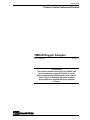
TMO2D Oxygen Analyzer
User’s Manual
910-084A5
!ATTENTION!
This manual contains instructions for TMO2D units
that use software versions STD.004.E or earlier.
Units manufactured in Waltham with serial numbers
below 1350 or in Shannon with serial numbers
below 300E were supplied with these software
versions.
4/8/92
TMO2D Oxygen Analyzer
iii
1/20/97
Warranty
The TMO2D Oxygen Analyzer is warranted by PANAMETRICS to
be free from defects in material and workmanship. Liability under
this warranty is limited to servicing, calibrating and replacing any
defective parts of the instrument. Fuses and batteries are specifically
excluded from any liability. This warranty is effective from the date
of delivery to the original purchaser. For the warranty to be valid, the
equipment must be determined by Panametrics to have been
defective. This warranty is effective with respect to the following:
•
one year for electronic failures
•
one year for mechanical failures (shorts or opens) to the transmitter
If damage is determined to have been caused by misuse or abnormal
conditions of operation, the owner will be notified and repairs will be
billed at standard rates after approval.
Maintenance Policy
If any problems develop, take the following steps:
•
Notify PANAMETRICS, giving full details of the problem. Be
sure to include the model and serial number of your O2 Analyzer.
PANAMETRICS will then give you a RETURN
AUTHORIZATION NUMBER if the analyzer has to be returned
to the factory.
•
If PANAMETRICS instructs you to send your O2 Analyzer back
to the factory, please send it prepaid to the authorized repair station
as indicated in the shipping instructions.
•
If damage has been caused by misuse, abnormal conditions, or if
the warranty has expired, an estimate will be made and provided
upon request before repairs are started.
The PANAMETRICS TMO2D Oxygen Analyzer warranty is limited
to that which is stated above; PANAMETRICS will not be liable for
anything beyond this.
©Copyright, Panametrics, Inc. 1997
iv
1/20/97
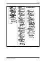
Table of Contents
Chapter 1: Features and Capabilities
Introduction to the TMO2D. . . . . . . . . . . . . . . . . . . . . . . . . . . . . . . . . . . . . . . . . . . . . . . . . . . . . .1-1
System Description . . . . . . . . . . . . . . . . . . . . . . . . . . . . . . . . . . . . . . . . . . . . . . . . . . . . . . . . . . . .1-1
The TMO2 Transmitter. . . . . . . . . . . . . . . . . . . . . . . . . . . . . . . . . . . . . . . . . . . . . . . . . . . . . .1-2
The TMO2D Electronics Display . . . . . . . . . . . . . . . . . . . . . . . . . . . . . . . . . . . . . . . . . . . . . .1-3
The Sample System. . . . . . . . . . . . . . . . . . . . . . . . . . . . . . . . . . . . . . . . . . . . . . . . . . . . . . . . .1-3
System Operation . . . . . . . . . . . . . . . . . . . . . . . . . . . . . . . . . . . . . . . . . . . . . . . . . . . . . . . . . . . . .1-4
Chapter 2: Installation
Introduction . . . . . . . . . . . . . . . . . . . . . . . . . . . . . . . . . . . . . . . . . . . . . . . . . . . . . . . . . . . . . . . . . .2-1
Mounting the TMO2 Transmitter . . . . . . . . . . . . . . . . . . . . . . . . . . . . . . . . . . . . . . . . . . . . . . . . .2-2
Mounting the TMO2 Sample System . . . . . . . . . . . . . . . . . . . . . . . . . . . . . . . . . . . . . . . . . . . . . .2-3
Mounting the TMO2D Electronic Display . . . . . . . . . . . . . . . . . . . . . . . . . . . . . . . . . . . . . . . . . .2-4
Making Wiring Connections . . . . . . . . . . . . . . . . . . . . . . . . . . . . . . . . . . . . . . . . . . . . . . . . . . . . .2-5
Wiring the Transmitter to the Display . . . . . . . . . . . . . . . . . . . . . . . . . . . . . . . . . . . . . . . . . .2-6
Wiring Recorders, AutoCal System, Alarms, etc. . . . . . . . . . . . . . . . . . . . . . . . . . . . . . . . . .2-8
RS-232C Serial Port . . . . . . . . . . . . . . . . . . . . . . . . . . . . . . . . . . . . . . . . . . . . . . . . . . . . . . . .2-9
Connecting Power . . . . . . . . . . . . . . . . . . . . . . . . . . . . . . . . . . . . . . . . . . . . . . . . . . . . . . . . .2-10
Chapter 3: Operation
Introduction . . . . . . . . . . . . . . . . . . . . . . . . . . . . . . . . . . . . . . . . . . . . . . . . . . . . . . . . . . . . . . . . . .3-1
Powering Up the TMO2D . . . . . . . . . . . . . . . . . . . . . . . . . . . . . . . . . . . . . . . . . . . . . . . . . . . . . . .3-1
Establishing Gas Flow . . . . . . . . . . . . . . . . . . . . . . . . . . . . . . . . . . . . . . . . . . . . . . . . . . . . . . . . . .3-1
Operating the Display . . . . . . . . . . . . . . . . . . . . . . . . . . . . . . . . . . . . . . . . . . . . . . . . . . . . . . . . . .3-1
The LCD Display. . . . . . . . . . . . . . . . . . . . . . . . . . . . . . . . . . . . . . . . . . . . . . . . . . . . . . . . . . . . . .3-2
The Keypad . . . . . . . . . . . . . . . . . . . . . . . . . . . . . . . . . . . . . . . . . . . . . . . . . . . . . . . . . . . . . . . . . .3-2
v
1/20/97
Table of Contents (cont.)
Chapter 4: Programming the TMO2D
Introduction . . . . . . . . . . . . . . . . . . . . . . . . . . . . . . . . . . . . . . . . . . . . . . . . . . . . . . . . . . . . . . . . . 4-1
Entering Data into the User Program . . . . . . . . . . . . . . . . . . . . . . . . . . . . . . . . . . . . . . . . . . . . . . 4-1
Key Functions . . . . . . . . . . . . . . . . . . . . . . . . . . . . . . . . . . . . . . . . . . . . . . . . . . . . . . . . . . . . 4-2
Programming the TMO2D via the Display . . . . . . . . . . . . . . . . . . . . . . . . . . . . . . . . . . . . . . . . . 4-2
Display Navigation . . . . . . . . . . . . . . . . . . . . . . . . . . . . . . . . . . . . . . . . . . . . . . . . . . . . . . . . 4-2
Menu Navigation . . . . . . . . . . . . . . . . . . . . . . . . . . . . . . . . . . . . . . . . . . . . . . . . . . . . . . . . . . 4-3
The Setup Menu . . . . . . . . . . . . . . . . . . . . . . . . . . . . . . . . . . . . . . . . . . . . . . . . . . . . . . . . . . . . . . 4-4
Set Time?. . . . . . . . . . . . . . . . . . . . . . . . . . . . . . . . . . . . . . . . . . . . . . . . . . . . . . . . . . . . . . . . 4-4
Set Date? . . . . . . . . . . . . . . . . . . . . . . . . . . . . . . . . . . . . . . . . . . . . . . . . . . . . . . . . . . . . . . . . 4-5
Set Backlight? . . . . . . . . . . . . . . . . . . . . . . . . . . . . . . . . . . . . . . . . . . . . . . . . . . . . . . . . . . . . 4-5
Set Display?. . . . . . . . . . . . . . . . . . . . . . . . . . . . . . . . . . . . . . . . . . . . . . . . . . . . . . . . . . . . . . 4-6
Set Communications? . . . . . . . . . . . . . . . . . . . . . . . . . . . . . . . . . . . . . . . . . . . . . . . . . . . . . . 4-6
The Recorder Menu . . . . . . . . . . . . . . . . . . . . . . . . . . . . . . . . . . . . . . . . . . . . . . . . . . . . . . . . . . . 4-9
The Alarm Menu . . . . . . . . . . . . . . . . . . . . . . . . . . . . . . . . . . . . . . . . . . . . . . . . . . . . . . . . . . . . 4-11
The Tests Menu . . . . . . . . . . . . . . . . . . . . . . . . . . . . . . . . . . . . . . . . . . . . . . . . . . . . . . . . . . . . . 4-13
DVM Test . . . . . . . . . . . . . . . . . . . . . . . . . . . . . . . . . . . . . . . . . . . . . . . . . . . . . . . . . . . . . . 4-13
Recorder Calibrate Test . . . . . . . . . . . . . . . . . . . . . . . . . . . . . . . . . . . . . . . . . . . . . . . . . . . . 4-14
Alarms Test . . . . . . . . . . . . . . . . . . . . . . . . . . . . . . . . . . . . . . . . . . . . . . . . . . . . . . . . . . . . . 4-15
The Calibration Menu . . . . . . . . . . . . . . . . . . . . . . . . . . . . . . . . . . . . . . . . . . . . . . . . . . . . . . . . 4-17
Auto Cal Parameters? . . . . . . . . . . . . . . . . . . . . . . . . . . . . . . . . . . . . . . . . . . . . . . . . . . . . . 4-17
Edit Calibration Data? . . . . . . . . . . . . . . . . . . . . . . . . . . . . . . . . . . . . . . . . . . . . . . . . . . . . . 4-30
Chapter 5: Specifications
TMO2 Oxygen Transmitter . . . . . . . . . . . . . . . . . . . . . . . . . . . . . . . . . . . . . . . . . . . . . . . . . . . . .
TMO2D Display Specifications. . . . . . . . . . . . . . . . . . . . . . . . . . . . . . . . . . . . . . . . . . . . . . . . . .
Performance. . . . . . . . . . . . . . . . . . . . . . . . . . . . . . . . . . . . . . . . . . . . . . . . . . . . . . . . . . . . . .
Functional . . . . . . . . . . . . . . . . . . . . . . . . . . . . . . . . . . . . . . . . . . . . . . . . . . . . . . . . . . . . . . .
Physical . . . . . . . . . . . . . . . . . . . . . . . . . . . . . . . . . . . . . . . . . . . . . . . . . . . . . . . . . . . . . . . . .
5-1
5-2
5-2
5-2
5-3
Appendix A: Thermoparamagnetic (Magnetic Wind) Theory
Basic Principle . . . . . . . . . . . . . . . . . . . . . . . . . . . . . . . . . . . . . . . . . . . . . . . . . . . . . . . . . . . . . . . A-1
The TMO2 Transmitter Oxygen Measurement Bridge . . . . . . . . . . . . . . . . . . . . . . . . . . . . . . . . A-1
The TMO2 Transmitter Compensation Bridge . . . . . . . . . . . . . . . . . . . . . . . . . . . . . . . . . . . . . . A-2
TMO2D Electronics Microprocessor-based Compensation for Variations in Background Gas
Composition . . . . . . . . . . . . . . . . . . . . . . . . . . . . . . . . . . . . . . . . . . . . . . . . . . . . . . . . . . . . . . . . . A-2
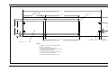
Appendix B: Outline and Installation Drawings
Appendix C: RS-232C Serial Port
RS-232C Serial Port. . . . . . . . . . . . . . . . . . . . . . . . . . . . . . . . . . . . . . . . . . . . . . . . . . . . . . . . . . . C-1
vi
1/20/97
Table of Contents (cont.)
Appendix D: The TMO2 Transmitter Calibration Procedure
Introduction . . . . . . . . . . . . . . . . . . . . . . . . . . . . . . . . . . . . . . . . . . . . . . . . . . . . . . . . . . . . . . . . .
Equipment and Drawings . . . . . . . . . . . . . . . . . . . . . . . . . . . . . . . . . . . . . . . . . . . . . . . . . . . . . .
Setup . . . . . . . . . . . . . . . . . . . . . . . . . . . . . . . . . . . . . . . . . . . . . . . . . . . . . . . . . . . . . . . . . . . . . .
Preliminary Explanation . . . . . . . . . . . . . . . . . . . . . . . . . . . . . . . . . . . . . . . . . . . . . . . . . . . . . . .
Internal Background Gas Compensation. . . . . . . . . . . . . . . . . . . . . . . . . . . . . . . . . . . . . . . . . . .
Zero: . . . . . . . . . . . . . . . . . . . . . . . . . . . . . . . . . . . . . . . . . . . . . . . . . . . . . . . . . . . . . . . . . . .
Span Compensation: . . . . . . . . . . . . . . . . . . . . . . . . . . . . . . . . . . . . . . . . . . . . . . . . . . . . . . .
External Compensation . . . . . . . . . . . . . . . . . . . . . . . . . . . . . . . . . . . . . . . . . . . . . . . . . . . . . . . .
Zero: . . . . . . . . . . . . . . . . . . . . . . . . . . . . . . . . . . . . . . . . . . . . . . . . . . . . . . . . . . . . . . . . . . .
Oxygen Span: . . . . . . . . . . . . . . . . . . . . . . . . . . . . . . . . . . . . . . . . . . . . . . . . . . . . . . . . . . . .
External Compensation: . . . . . . . . . . . . . . . . . . . . . . . . . . . . . . . . . . . . . . . . . . . . . . . . . . . .
Internal Pressure Compensation . . . . . . . . . . . . . . . . . . . . . . . . . . . . . . . . . . . . . . . . . . . . . . . . .
Zero: . . . . . . . . . . . . . . . . . . . . . . . . . . . . . . . . . . . . . . . . . . . . . . . . . . . . . . . . . . . . . . . . . . .
Span Compensation: . . . . . . . . . . . . . . . . . . . . . . . . . . . . . . . . . . . . . . . . . . . . . . . . . . . . . . .
External Pressure Signal Calibration. . . . . . . . . . . . . . . . . . . . . . . . . . . . . . . . . . . . . . . . . . . . . .
Zero: . . . . . . . . . . . . . . . . . . . . . . . . . . . . . . . . . . . . . . . . . . . . . . . . . . . . . . . . . . . . . . . . . . .
Oxygen Span: . . . . . . . . . . . . . . . . . . . . . . . . . . . . . . . . . . . . . . . . . . . . . . . . . . . . . . . . . . . .
External Pressure Signal: . . . . . . . . . . . . . . . . . . . . . . . . . . . . . . . . . . . . . . . . . . . . . . . . . . .
Internal Hydrogen Gas Compensation . . . . . . . . . . . . . . . . . . . . . . . . . . . . . . . . . . . . . . . . . . . .
Zero: . . . . . . . . . . . . . . . . . . . . . . . . . . . . . . . . . . . . . . . . . . . . . . . . . . . . . . . . . . . . . . . . . . .
Span Compensation: . . . . . . . . . . . . . . . . . . . . . . . . . . . . . . . . . . . . . . . . . . . . . . . . . . . . . . .
External Hydrogen Gas Compensation . . . . . . . . . . . . . . . . . . . . . . . . . . . . . . . . . . . . . . . . . . . .
Internal Methane Gas Compensation
(Reverse Compensation) . . . . . . . . . . . . . . . . . . . . . . . . . . . . . . . . . . . . . . . . . . . . . . . . . . . . . . .
Zero: . . . . . . . . . . . . . . . . . . . . . . . . . . . . . . . . . . . . . . . . . . . . . . . . . . . . . . . . . . . . . . . . . . .
Span Compensation: . . . . . . . . . . . . . . . . . . . . . . . . . . . . . . . . . . . . . . . . . . . . . . . . . . . . . . .
D-1
D-2
D-3
D-3
D-5
D-5
D-6
D-6
D-6
D-6
D-7
D-7
D-8
D-8
D-8
D-8
D-8
D-9
D-9
D-9
D-9
D-9
D-9
D-9
D-9
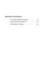
Appendix E: Main Menu Flow Diagrams
Appendix F: Installation Instructions for CE Mark Compliance
Installation Instructions for CE Mark Compliance . . . . . . . . . . . . . . . . . . . . . . . . . . . . . . . . . . . .F-1
vii
Chapter 1
Features and Capabilities
Introduction to the TMO2D . . . . . . . . . . . . . . . . . . . . . . . . . . . . . . . 1-1
System Description . . . . . . . . . . . . . . . . . . . . . . . . . . . . . . . . . . . . .1-1
System Operation. . . . . . . . . . . . . . . . . . . . . . . . . . . . . . . . . . . . . . . 1-4
11/30/92
Introduction to the
TMO2D
In this section you will find the following:
•
An introduction to the TMO2D Oxygen Analyzer and its
components
•
A description of the TMO2D configurations and accessories
•
A brief discussion of the TMO2D operating system
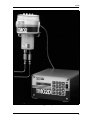
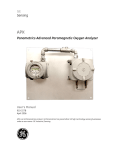
The TMO2D Oxygen Analyzer is a complete system that measures
oxygen concentration from 0-100% in gaseous mixtures. The main
components of the Analyzer are the TMO2 Transmitter (a measuring
cell mounted within an aluminum housing) and the TMO2D
Electronic Display.
The TMO2D Electronic Display is connected to the TMO2
Transmitter via a 3- or 4-wire non-shielded cable. The Electronic
Display provides user-friendly software that allows you to enter
parameters specific to your process application, i.e., your O2 range,
recorder output range, alarm settings, etc.
System Description
The TMO2D Oxygen Analyzer is configured with the following
components and accessories:
•
The TMO2 Transmitter
•
The TMO2D Electronic Display
•
The Sample System (specific to your application) on which the
Transmitter is mounted
•
A three- or four-wire color coded cable, T(*) N4
Note: All applications require a sample system; consult Panametrics
whether you are ordering a sample system or planning to
build one.
Features and Capabilities
1-1
11/30/92
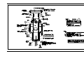
The TMO2 Transmitter
The TMO2 Transmitter is self-contained, consisting of the oxygen
measuring cell and associated electronics enclosed in a cast
aluminum housing (see Appendix B for outline and installation
dimension drawings).
The Transmitter has no moving parts. It requires 24 VDC power and
outputs a 4-20 or 0-20 mA signal proportional to oxygen
concentration. It can also output an optional pressure or background
gas compensation signal. The Transmitter housing is weatherproof
and can be made explosion-proof with inlet and outlet flame arrestors
(see Figure 1-1 below).
Inlet
Outlet
Flame Arrestors
Figure 1-1: TMO2 Transmitter with Inlet and Outlet Piping
1-2
Features and Capabilities
4/8/92
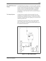
The TMO2D Electronics
Display
The TMO2D Electronics Display is an electronic module containing
user-friendly software that allows you to enter specific parameters for
O2 range, recorder output range, alarm settings, etc. The Display
features a two-line by 24-character backlit liquid crystal display
(LCD) and comes in either rack, bench, panel or weatherproof
configurations. A color-coded cable is used to connect the Display to
the Transmitter.
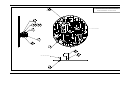
The Sample System
A Sample System is required to bring a gas sample flow to the
Transmitter at a well-defined pressure. The Sample System design
will depend on the application. Generally, it consists of the mounted
Transmitter, a sample gas inlet, flow regulating valve, flow meter, and
calibration gas inlet valves.
The Sample System may also include a pressure gauge/regulator,
pump, aspirator, coalescer/filter, or other components. Figure 1-2
below is an illustration of a Sample System which includes most of
the components described above.
Figure 1-2: A TMO2 Sample System
Features and Capabilities
1-3
11/30/92
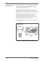
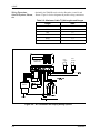
System Operation
The TMO2 Transmitter uses the thermoparamagnetic (“magnetic
wind”) principle to measure oxygen concentration in gases (see
Appendix A for “magnetic wind” theory).
During operation, the TMO2 Transmitter generates an electrical
signal proportional to oxygen concentration, and (optionally) one
additional signal for either background gas or pressure compensation.
The TMO2D Electronics Display accepts the oxygen and
compensation signals from the Transmitter and, using transmitter
calibration, background gas compensation, and pressure
compensation data, calculates oxygen concentration and displays it as
a percentage of the sample (see Figure 1-3 below).
Note: The TMO2D milliamp output range can be independent of the
Display range.
Figure 1-3: TMO2 Transmitter and TMO2D Display
1-4
Features and Capabilities
Chapter 2
Installation
Introduction . . . . . . . . . . . . . . . . . . . . . . . . . . . . . . . . . . . . . . . . . . . 2-1
Mounting the TMO2 Transmitter . . . . . . . . . . . . . . . . . . . . . . . . . . .2-2
Mounting the TMO2 Sample System . . . . . . . . . . . . . . . . . . . . . . . 2-3
Mounting the TMO2D Electronic Display . . . . . . . . . . . . . . . . . . . . 2-4
Making Wiring Connections . . . . . . . . . . . . . . . . . . . . . . . . . . . . . . 2-5
1/20/97
Introduction
This section provides information on how to mount and wire the
Transmitter and Display. Read this section if you are installing the
TMO2D for the first time. A typical TMO2D installation consists of
the following:
•
Mounting the TMO2 Transmitter
•
Mounting the TMO2 Sample System
•
Mounting the TMO2D Electronic Display
•
Wiring the Transmitter to the Display
•
Wiring Recorders, AutoCal System, Alarms, etc.
•
Connecting Power
Caution!
The interconnecting wiring between the transmitter and
display must be completed before powering up.
!WARNING!
TO ENSURE THE SAFE OPERATION OF THE
TMO2D, YOU MUST INSTALL AND OPERATE IT AS
DESCRIBED IN THIS MANUAL. IN ADDITION, BE
SURE TO FOLLOW ALL APPLICABLE SAFETY
CODES AND REGULATIONS FOR INSTALLING
ELECTRICAL EQUIPMENT IN YOUR AREA.
ALL INSTALLATION PROCEDURES SHOULD BE
PERFORMED BY TRAINED SERVICE PERSONNEL.
Installation
2-1
1/20/97
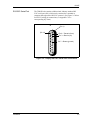
Mounting the TMO2
Transmitter
The TMO2 Transmitter is shown in Figure 2-1 below. For optimum
response, mount it as close as possible to the process being monitored
(preferably within 5 feet (1.52 meters)). Be sure to keep the
Transmitter level to within 15° of vertical and provide at least 9
inches of clearance above the top cover of the Transmitter to allow
access to the printed circuit board (PC Board) for calibration and
maintenance.
Note: Be sure to have the correct certified configuration if the
Transmitter is mounted in a hazardous area. Ambient
temperature must be -20°C to 40°C (-4° to 104°F).
Figure 2-1: The TMO2 Transmitter in Mounted Position
2-2
Installation
1/20/97
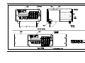
Mounting the TMO2
Sample System
A complete Sample System includes the Transmitter and associated
sample tubing and components already mounted to a metal panel.
Figure 2-2 below shows a Sample System which includes calibration
gas inlet valves, filter/coalescer with drain valve, pressure regulator
and bypass flowmeter in addition to the mandatory sample flow meter
and flow regulating valve.
Mount the TMO2 Sample System as close to the process as possible.
Once the Sample System is mounted, connect the oxygen sample
input and output lines via the 1/4" tube fittings at the bottom of the
Transmitter.
The sample line is generally recommended to be 1/4" stainless steel
tube and 1/4" stainless steel tube fittings. Attempt to minimize the
sample line length. Similarly connect calibration gas inlets, sample
outlets, bypass outlet, and filter/coalescer drain as applicable.
Figure 2-2: A Mounted TMO2 Sample System
Installation
2-3
1/20/97
Mounting the TMO2D
Electronic Display
The Electronic Display comes in four mounting configurations:
bench, rack, panel, and weatherproof mount (see Appendix B for
mounting dimensions).
No special mounting requirements are needed for the Display. If you
have a bench mount, simply put the Display in a convenient location,
connect the wires from the Transmitter, and connect the power. If you
have a rack or panel mount, insert the Display into the rack or panel,
connect the wires from the Transmitter, and connect the power. The
weatherproof model can be similarly mounted.
Note: The power cord is the main disconnect device.
IMPORTANT: To comply with the European Low Voltage Directive,
you must install a switch or circuit breaker on the
input power line. For greatest safety, locate the
circuit breaker or switch near the unit that the line
serves.
2-4
Installation
1/20/97
Making Wiring
Connections
Normally, a 3- or 4-wire, color-coded cable is supplied to connect the
Transmitter to the Display.
First make wiring connections from Terminal Block 1 (TB1) pins 1-4
on the Transmitter PC Board to the OXYGEN CELL Terminal Block
located on the rear panel of the Display.
!ATTENTION EUROPEAN CUSTOMERS!
IN ORDER TO MEET CE MARK REQUIREMENTS,
YOU MUST SHIELD AND GROUND ELECTRICAL
CABLES AS DESCRIBED IN APPENDIX F.
Installation
2-5
1/20/97
Wiring the Transmitter to
the Display
Remove the Transmitter cover by loosening the set screw and
unscrewing the cover. The Transmitter PC board is located directly
beneath (see Figure 2-3 below).
Note: There is a “1” printed on the PC Board next to the #1 pin
connection on TB1.
1. Route the cable into the Transmitter through one of the 3/4"
conduit holes on the side of the Transmitter.
2. Unplug TB1 on the Transmitter PC Board by carefully pulling it
directly up without bending the pins attached to the board.
3. Loosen the TB1 sidescrews and insert the colored wires into the
corresponding openings on top of TB1 (see Table 2-1 on page 2-7
for color-coded pin connections).
4. Tighten the sidescrews and carefully plug TB1 back onto the PC
Board.
5. Similarly connect the cable to the OXYGEN CELL Terminal
Block located on the rear panel of the Display (see Table 2-1 for
color-coded pin connections).
Figure 2-3: Top View of Transmitter PCB and TB1
= Protective Conductor Terminal
2-6
Installation
1/20/97
Wiring the Transmitter to
the Display (cont.)
Table 2-1: Transmitter to Display Wiring Pin Connections
Transmitter
Terminal Block
Display Terminal
Block
Power +24VDC
Red
Pin 1
Pin 1
Power Return
Black
Pin 2
Pin 2
Oxygen
White
Pin 3
Pin 3
Compensation
Blue or Green
Pin 4
Pin 4
Wire Connections
!WARNING!
BE SURE TO PLUG UP THE UNUSED CONDUIT
HOLE ON THE SIDE OF THE TRANSMITTER TO
MAINTAIN THE APPROPRIATE WEATHERPROOF
OR EXPLOSION-PROOF RATING.
Note: Refer to Figure 2-4 on the following page for a detailed
description of all wiring connections.
Installation
2-7
1/20/97
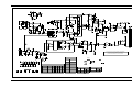
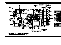
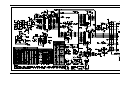
Wiring Recorders,
AutoCal System, Alarms,
etc.
Optionally, the TMO2D can be wired to Recorders, AutoCal, and
Alarms. Figure 2-4 below diagrams all possible wiring connections.
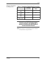
Table 2-2: Maximum Cable T(*)N4 Lengths and Gauges
Length
AWG
300’
22
500’
20
800’
18
1250’
16
2000’
14
3125’
12
+,*+
$/$50
702'
2;<*(1
&HOO
63$5( 5(&25'(56
,13876 P$
$872&$/
/2:
$/$50
$/$506
5 &2 5(&$5(&% 352&(66&$/ /2:+,*+
9 71 2; 0 9 517 1, ,1 &1&12&1&12&1&12&1&12
3
$/$50
32:(5
5(&25'(5
$
B
62/(12,'9$/9(
32:(5
702
237,21$/
5(&25'(5
%
B
=(52
*$6
287/(7
63$1
*$6
352&(66*$6,1/(7
$872&$/,%5$7,216<67(0
Figure 2-4: All Transmitter and Display Wiring Options
2-8
Installation
1/20/97
RS-232C Serial Port
The TMO2D also contains a bidirectional, industry standard RS232C serial port (#J8), which can be connected to a terminal or
computer that supports the RS-232C protocol. (See Figure 2-5 below
for RS-232 wiring pin connections; see Appendix C for a
corresponding key chart.)
J8
(Pin 14)
(Pin 1)
Pin 2 = Transmit (from)
Pin 3 = Receive (to)
Pin 7 = Return (ground)
Figure 2-5: Display RS-232C Serial Port Connections
Installation
2-9
1/20/97
Connecting Power
Once you have mounted and connected the Transmitter and Display,
and (if applicable) wired recorders, alarms, etc., connect the Display
to one of the following power supplies:
•
Japan, 100 VAC
•
U.S., 110/120 VAC
•
Europe, 220 VAC
•
Australia, 240 VAC
Caution!
The interconnecting wiring between the Transmitter and
Display must be completed before powering up.
Note: The power cord is the main disconnect device.
IMPORTANT: To comply with the European Low Voltage Directive,
you must install a switch or circuit breaker on the
input power line. For greatest safety, locate the
circuit breaker or switch near the unit that the line
serves.
= Protective Conductor Terminal
2-10
Installation
Chapter 3
Operation
Introduction . . . . . . . . . . . . . . . . . . . . . . . . . . . . . . . . . . . . . . . . . . . 3-1
Powering Up the TMO2D . . . . . . . . . . . . . . . . . . . . . . . . . . . . . . . . . 3-1
Establishing Gas Flow . . . . . . . . . . . . . . . . . . . . . . . . . . . . . . . . . . . 3-1
Operating the Display . . . . . . . . . . . . . . . . . . . . . . . . . . . . . . . . . . . 3-1
The LCD Display. . . . . . . . . . . . . . . . . . . . . . . . . . . . . . . . . . . . . . . . 3-2
The Keypad . . . . . . . . . . . . . . . . . . . . . . . . . . . . . . . . . . . . . . . . . . . . 3-2
11/30/92
Introduction
Once the TMO2D has been installed, the analyzer must be powered
up and a gas flow must be established before operating the analyzer
via the Electronics Display.
This section covers the following:
•
Powering Up The Transmitter
•
Establishing Gas Flow
•
Operating The Electronic Display
Powering Up the
TMO2D
The Transmitter has no power switch and will begin operating once it
has been connected to the Display and the power has been turned on.
Allow 90 minutes after power is turned on for the Transmitter to
warm-up and stabilize. During this time, establish gas flow through
the system.
Establishing Gas Flow
Open the necessary valves to establish the flow at 1.0 ±0.2 SCFH
(500 ±100 cc/min). Make sure that nothing impedes the flow of gas
thereby causing a pressure or vacuum buildup within the Transmitter.
For proper operation the Transmitter should be vented to the
atmosphere.
Note: The Transmitter has been calibrated at atmospheric pressure.
Unless pressure compensation is being used, operating the
Transmitter at other pressures will cause erroneous readings.
Operating the Display
The Electronic Display unit contains a 2-line by 24-character backlit
Liquid Crystal Display screen (LCD). On power-up, the Display unit
tests its memory (RAM) then searches for valid calibration data from
the Display as well as input from the TMO2 Transmitter.
If calibration data has already been entered into the Display, the unit
immediately begins taking measurements from the Transmitter and
the LCD begins displaying percent oxygen concentration.
If valid calibration data has not been entered and stored in the
Display, or if the the Transmitter is not hooked up to the Display, the
LCD will display erroneous readings. (Proceed to Chapter 4, page 41, to enter data into the Display.)
Operation
3-1
11/30/92
The LCD Display
The TMO2D is operated via the Display keypad. In order to facilitate
operation, it is important to familiarize yourself with the Display and
keypad functions
The first line of the LCD screen displays the current measurement
source or menu title and a real-time clock. The second line of the
LCD screen displays the measured data on the left and the current
alarm condition on the right (see Figure 3-1 below).
Note: The LCD contains an electroluminescent (EL) panel to
enhance readability of the screen during operation. To
activate the EL panel, press any key except the NO key.
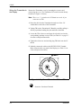
The Keypad
For operational purposes, the keypad (Figure 3-1 below) contains the
digits 0-9, a minus sign, a decimal point, and four special operations
keys:
•
YES
•
NO
•
Left Arrow
•
Right Arrow
Note: For details on how to use the keypad to program the Display,
refer to Chapter 4.
Figure 3-1: TMO2D Display and Keypad
3-2
Operation
Chapter 4
Programming the TMO2D
Introduction . . . . . . . . . . . . . . . . . . . . . . . . . . . . . . . . . . . . . . . . . . . 4-1
Entering Data into the User Program . . . . . . . . . . . . . . . . . . . . . . . 4-1
Programming the TMO2D via the Display . . . . . . . . . . . . . . . . . . . 4-2
The Setup Menu . . . . . . . . . . . . . . . . . . . . . . . . . . . . . . . . . . . . . . . . 4-4
The Recorder Menu . . . . . . . . . . . . . . . . . . . . . . . . . . . . . . . . . . . . .4-9
The Alarm Menu . . . . . . . . . . . . . . . . . . . . . . . . . . . . . . . . . . . . . . . 4-11
The Tests Menu . . . . . . . . . . . . . . . . . . . . . . . . . . . . . . . . . . . . . . .4-13
The Calibration Menu. . . . . . . . . . . . . . . . . . . . . . . . . . . . . . . . . . .4-17
9/30/93
Introduction
The TMO2D contains an interactive user-friendly program that
allows the user to change operating parameters as desired.
The user program has six main menus. Use the front panel keypad
and display to check or change the current operating parameter
settings. Data is stored in memory and is retained for several years,
even if the main power is lost. New data overrides any previously
entered data.
The user program consists of the following six main menus:
Entering Data into the
User Program
•
Setup
•
Recorders
•
Alarms
•
Test
•
Calibration
•
Resume
To enter data into the user program or to check previously entered
values, enter the Menu Mode. When power is turned on, the TMO2D
is in the Operate Mode. To enter the Menu Mode:
1. Press the NO key.
2. Key in the code 1 2 3. The TMO2D will display an asterisk (*)
after each digit is entered.
The LCD screen now displays the Setup Menu, the first of the six
main menus. At this display press YES to enter this menu, or NO to
go on. Pressing NO continuously scrolls through all six main menus.
Note: The first five options are main menus, the “RESUME” prompt
is used to exit the Menu Mode and return to Operate Mode.
If an incorrect code is entered or a non-numeric (YES/NO or arrow)
key is pressed rather than 1 2 3, the LCD will automatically resume
displaying data, and the user must press NO to re-attempt the code.
Once all three digits have been entered correctly, the Display will
cease collecting data and the LCD will switch to Menu Mode.
Programming the TMO2D
4-1
9/30/93
Key Functions
The YES key is used to confirm numeric entries or to select a
displayed menu option.
The NO key is used to clear a numeric entry or to scroll forward
through the menu options.
The Left Arrow key has two functions:
•
It is used as a backspace key during numeric entry. The right most
digit of the entry will be erased for each press of the left arrow.
•
It is used to step backward through a list of menu options.
The Right Arrow key is used to scroll forward through the menu
options. It is equivalent to pressing the NO key in the Menu Mode.
Programming the
TMO2D via the Display
This section gives a brief explanation of Display and menu navigation
and then takes you through the programming procedure.
Display Navigation
On power-up, the first line of the LCD screen contains the current
measurement source and a real-time clock. The second line of the
LCD contains the measured data on the left and the current alarm
condition on the right (see Figure 4-1 below).
Figure 4-1: TMO2 Display and Keypad
While displaying oxygen concentration, the Display will ignore all
keys except the NO key. On receipt of a NO, the LCD will begin
displaying “Enter Code:” and await the program entry code, 1 2 3.
During code entry the Display continues to update the data display,
alarm status, and recorder ouput.
4-2
Programming the TMO2D
9/30/93
Menu Navigation
After the passcode 1 2 3 is entered, the LCD switches to Menu Mode,
which allows programming of the Display, i.e., setting parameters and
calibration data, performing alarm and recorder tests. While in Menu
Mode, data collection is suspended and alarm status and recorder
outputs hold their current values.
In Menu Mode, the first line of the LCD shows the title of the current
menu in capital letters. The second line displays the current menu
options.
The two types of response keys available in the Menu Mode are YES/
NO and Selector keys. Pressing YES selects the displayed option.
Pressing NO skips that option and displays the next option in the list.
The Selector option is used to choose between two or three possible
choices in the menu.
Note: The menu lists are circular, i.e., skipping over the last option
in the list returns to the first option in the list.
The following sections describe the programming procedure and
menu navigation in detail one menu at a time. (Also refer to Appendix
E for flow diagrams of each menu.)
Programming the TMO2D
4-3
9/30/93
The Setup Menu
The first Main Menu is the Setup Menu. The Setup Menu contains the
following six submenus:
•
Set Time
•
Set Date
•
Set Backlight
•
Set Display
•
Set Communications
•
Done
These submenus allow the user to alter operating parameters. Once
entered, these values will remain in the Display memory until they are
changed. (Refer to Appendix E for a flow diagram of the Setup
Menu.)
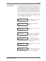
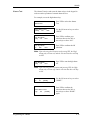
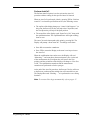
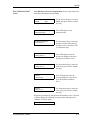
Set Time?
The first display in the Setup Menu is “Set Time?,” which sets the
current time in 24-hour format. For example, to enter 1:15 pm (13.15
in 24-hour time):
:
4-4
MAIN MENU
Setup?
Press YES to enter the Setup
Menu.
SETUP MENU
Set Time?
Press YES to set the time.
Enter 24 hour time:
HH.MM [XX.XX]: 13.15
Then use the numeric keys to enter
a 1, 3, . , 1 and 5. (The X’s
represent the previous time
entered.)
Enter 24 hour time:
HH.MM [13.15]:
Press YES to confirm the entry.
Press YES again to exit.
SETUP MENU
Set Time?
Press NO to proceed to the next
submenu.
Programming the TMO2D
9/30/93
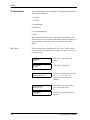
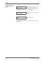
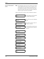
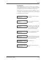
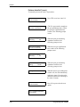
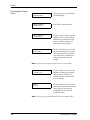
Set Date?
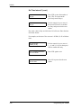
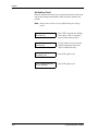
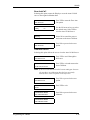
Set Backlight?
Programming the TMO2D
The Set Date submenu is used to set the current date in USA (month,
day, year) format. For example, to enter February 24, 1991:
SETUP MENU
Set Date?
Press YES to set the date.
Enter Date (MM.DD.YY):
[XX.XX.XX]:2.24.91
Then use the numeric keys to enter
a 2, 24, and 91. (The X’s represent
the previous date entered.)
Enter Date (MM.DD.YY):
2.24.91
Press YES to confirm the entry.
SETUP MENU
Set Date?
Press YES again to exit.
SETUP MENU
Set Backlight?
Press NO to proceed to the next
submenu.
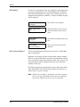
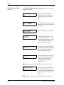
The LCD contains an electroluminescent (EL) panel to enhance the
readability of the screen in dim light. EL panels have a finite life
span, dimming with use. To maintain the life of the EL backlight, the
Display will automatically turn the backlight off after a
predetermined time period. The Backlight time-out period can be set
from 0 (never on) to 60 minutes. The default timeout is 3 minutes. For
example, to set this time to 10 minutes:
SETUP MENU
Set Backlight?
Press YES to set the backlight.
SETUP MENU
Remain ON (min) [X]: 10
Then use the numeric keys to enter
10. (The X’s represent the previous
time entered.)
SETUP MENU
Remain ON (min) [10]:
Press YES to confirm the entry.
SETUP MENU
Set Backlight?
Press YES again to exit.
SETUP MENU
Set Display?
Press NO to proceed to the next
submenu.
4-5
9/30/93
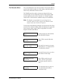
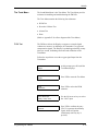
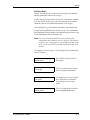
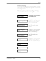
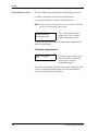
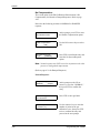
Set Display?
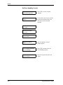
Set Communications?
In order for a compensation value to be displayed, either background
or pressure compensation must be enabled through the Calibration:
Edit Calibration Data Menu (see page 4-30). If neither pressure nor
background compensation is enabled, a “Comp not enabled” message
will be displayed.
SETUP MENU
Set Display?
Press YES to set the display.
Display Compensation
[YES]
no
Then use the NO or arrow keys to
move the brackets to the desired
entry.
SETUP MENU
Set Display?
Press YES to confirm the entry and
exit.
SETUP MENU
Set Communications?
Press NO to proceed to the next
submenu.
The Set Communications submenu has two choices: (1) Baud Rate,
and (2) Update Rate.
Baud Rate: The Display contains a bi-directional, industry standard
RS-232C serial port that allows operation of the instrument remotely
with a terminal or computer that supports the RS-232C protocol. All
keypad operations and most display operations can be performed
remotely via this port.
The Display supports the communication rates of 9600, 4800, 2400,
1200, and 300 baud. The default setting is 9600 baud. Word size is
fixed at 8 bits, 1 stop bit, no parity.
Note: 300 baud is provided for compatibility with older equipment;
however, the use of 300 baud greatly limits the computation
speed of the TMO2D, and its use is not recommended.
4-6
Programming the TMO2D
9/30/93
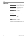
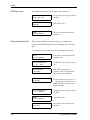
Set Communications?
(cont.)
The Set Communications submenu is used to set a baud rate and an
update rate.
SETUP MENU
Set Communications?
Press YES to enter the Set
Communications submenu.
SET COMMUNICATIONS
Set Baud Rate?
Press YES to enter the baud rate.
SELECT BAUD RATE
9600 baud?
Use the NO or arrow keys to scroll
through the choices.
SELECT BAUD RATE
4800 baud?
SELECT BAUD RATE
2400 baud?
SELECT BAUD RATE
1200 baud?
SELECT BAUD RATE
300 baud?
Press YES to select the desired
baud rate and exit.
SET COMMUNICATIONS
Set Baud Rate?
Press NO to proceed to the next
submenu.
Note: The baud rate can be changed via a terminal connected to the
RS-232C port. However, this is not recommended, as the
TMO2D will immediately change to the new baud rate.
Display and keyboard operation will not be correct until the
baud rate of the terminal is changed to match the new baud
rate set in the TMO2D.
SET COMMUNICATIONS
Set Update Rate?
Programming the TMO2D
Press YES to set the update rate.
4-7
9/30/93
Set Communications?
(cont.)
Update Rate: This option is used to change the interval at which data
goes to the serial port. The current data interval will appear in
brackets, and users can enter a new data interval.
Data intervals range from 0 to 300 seconds. A data rate of zero will
prevent data from passing to the serial port.
SET COMMUNICATIONS
Set Update Rate?
Press YES to set the update rate.
SET COMMUNICATIONS
Data Interval [X]: 180
For example, enter 1, 8 and 0 for a
180 sec (3 min) interval. (The X
represents the previously entered
data interval.).
SET COMMUNICATIONS
Data Interval [180]:
Press YES to confirm the entry.
SET COMMUNICATIONS
Set Update Rate?
Press YES again to exit.
SET COMMUNICATIONS
Done?
Press NO to proceed to the next
submenu.
SETUP MENU
Set Communications?
Press YES to exit.
SETUP MENU
Done?
Press NO to proceed to the next
submenu.
MAIN MENU
Setup?
Press YES to exit.
This completes the Setup Menu. Press NO to proceed to the next
Main Menu title.
4-8
Programming the TMO2D
9/30/93
The Recorder Menu
The second Main Menu is the Recorder Menu. The Recorder Menu is
used to select which recorder (A or B) to adjust, and allows entry of
all necessary information for that recorder.
The TMO2D provides a choice of one non-isolated 0/4-20 mA
recorder output, or two isolated 0/4-20 mA recorder outputs. Both
recorder options can be set for a 0-20 mA or a 4-20 mA response.
Output can be scaled anywhere within the range of the transmitter.
Note: The Display is programmed to accept settings for two
recorders; however, if only a single, non-isolated recorder
output is used, only recorder A is effective.
Use the steps in the following example to set up recorders. We will set
recorder A for a 0-20 mA output, with 0 mA equal to 0% oxygen and
20 mA equal to 100% oxygen. (Refer to Appendix E for a flow
diagram of the Recorder Menu.)
Programming the TMO2D
MAIN MENU
Setup?
At this prompt, press NO until the
Recorder Menu displays.
MAIN MENU
Recorders?
Press YES to enter the Recorder
Menu.
Select Recorder to set:
[A]
B
done
Use the NO or arrow keys to move
the brackets to “A,” and press YES
to confirm the selection.
Rcd A Output (mA):
[0-20]
4-20
Use the NO or arrow keys to select
the desired recorder range..
Recorder A 0 mA Value
%O2 [X.XX]:
Press YES to set the low end
value. (The X’s represent the
previously entered value for 0
mA.)
Recorder A 0 mA Value
%O2 [0.00]:
Use the numeric keys to enter a 0,
., 0, and 0, then press YES to
confirm the entry.
4-9
9/30/93
The Recorder Menu
(cont.)
Recorder A 20 mA Value
%O2 [X.XX]:
Press YES again to proceed to the
high end value. (The X’s represent
the previously entered value for 20
mA.)
Recorder A 20 mA Value
%O2 [100.0]:
Use the numeric keys to enter a 1,
0, 0, ., and 0, then press YES to
confirm the entry.
Select Recorder to set:
[A]
B
done
Press YES to exit.
Recorder B is programmed the same way. After entering the
necessary values:
Select Recorder to set:
A
B
[DONE]
Use the NO or arrow keys to select
“DONE.”
MAIN MENU
Recorders?
Press YES to exit.
This completes the Recorder Menu. Press NO to proceed to the next
Main Menu title.
4-10
Programming the TMO2D
9/30/93
The Alarm Menu
The third Main Menu is the Alarm Menu. The TMO2D is provided
with two four-pole double throw relays for use in activating alarm
devices. Both relays provide a normally-open and a normally-closed
set of contacts. The alarms are addressed as HIGH and LOW. The
HIGH alarm relay will trip when the current reading is greater than or
equal to the high alarm setpoint. The LOW alarm relay will trip when
the current reading is less than or equal to the low alarm setpoint.
Use the steps in the following example to set the high alarm setpoint
to 75% O2 and the low alarm setpoint to 25% O2. (Refer to Appendix
E for a flow diagram of the Alarm Menu.)
Programming the TMO2D
MAIN MENU
Setup?
At this prompt, press NO until the
Alarm Menu displays.
MAIN MENU
Alarms?
Press YES to enter the Alarm
Menu.
Select Alarm to set:
[HIGH] low done
Use the NO or arrow keys to select
“HIGH.”
Enter Alarm Setpoint:
High %O2 [X.XX]:
Press YES to enter the high alarm
setpoint. (The X’s represent the
previously entered setpoint.)
Enter Alarm Setpoint:
High %O2 [75.0]:
Use the numeric keys to enter 7
and 5, then press YES twice to
confirm the entry and proceed to
the next prompt.
Select Alarm to set:
high [LOW] done
Use the NO or arrow keys to select
“LOW.”
Enter Alarm Setpoint:
Low %O2 [X.XX]:
Press YES to enter the low alarm
setpoint. (The X’s represent the
previously entered setpoint.)
4-11
9/30/93
The Alarms Menu
(cont.)
Enter Alarm Setpoint:
Low %O2 [25.0]:
Use the numeric keys to enter 2
and 5, then press YES twice to
confirm the entry and proceed to
the next prompt.
Select Alarm to set:
high low [DONE]
Use the NO or arrow keys to select
“DONE.”
MAIN MENU
Alarms?
Press YES to exit.
This completes the Alarms Menu. Press NO to proceed to the next
Main Menu title.
4-12
Programming the TMO2D
9/30/93
The Tests Menu
The fourth Main Menu is the Tests Menu. The Tests Menu provides
assistance in installing and troubleshooting the TMO2D.
The Tests Menu contains the following four submenus:
•
DVM Test
•
Recorder Calibrate Test
•
Alarms Test
•
Done
(Refer to Appendix E for a flow diagram of the Tests Menu.)
DVM Test
The DVM test allows the Display to operate as a simple digital
voltmeter to measure, in milliamps, the Transmitter’s oxygen and
compensation signals. The Display is updated approximately twenty
times per second, facilitating connection and calibration of the
Transmitter.
Follow the steps below to test the oxygen signal input from the
Transmitter.
Programming the TMO2D
MAIN MENU
Setup?
At this prompt, press NO until the
Test Menu displays.
MAIN MENU
Tests?
Press YES to enter the Test Menu.
Tests
DVM Test?
Press YES to select the DVM
submenu.
Select DVM Input:
[GAS] comp done
Use the NO or arrow keys to select
the “GAS” input.
O2 DVM TEST
X.XX mA
Press YES to confirm the entry.
(The X’s represent the milliamp
signal, which will update
continuously until any key is
pressed.)
4-13
9/30/93
DVM Test (cont.)
Recorder Calibrate Test
The compensation signal input is displayed the same way.
Select DVM Input:
[GAS] comp done
Use the NO or arrow keys to select
“DONE.”
TESTS
DVM Test?
Press YES to exit.
TESTS
Recorder Calibrate?
Press NO to proceed to the next
submenu.
The Recorder Calibrate Test allows a %O2 to be output to the
recorder to facilitate adjustment of the recording device’s zero and
span.
For example, to enter a %O2 of 36.39 to be output to recorder A:
4-14
TESTS
Recorder Calibrate?
Press YES to select the Recorder
Calibrate Test.
Select Recorder to test:
[A]
B
done
Use the NO or arrow keys to select
“A.”
Set Recorder A to:
%O2 [XX.XX]:
Press YES to confirm your
selection. (The X’s represent the
previously entered setpoint.)
Set Recorder A to:
%O2 [36.39]:
Use the numeric keys to enter 3, 6,
., 3, and 9, then press YES twice to
confirm the entry and proceed to
the next prompt.
Select Recorder to test:
A
B
[DONE]
Use the NO or arrow keys to select
“DONE.”
TESTS
Recorder Calibrate?
Press YES to exit.
TESTS
Alarms Test?
Press NO to proceed to the next
submenu.
Programming the TMO2D
9/30/93
Alarms Test
The Alarms Test trips and resets the alarm relays via the keypad in
order to test the operation of external alarm devices.
For example, to test the high alarm relay:
TESTS
Alarms Test?
Press YES to select the Alarms
Test.
Select Alarm to test:
[HIGH]
low
done
Use the NO or arrow keys to select
“HIGH.”
Turn High Alarm:
[ON]
off
done
Press YES to confirm your
selection, then use the NO or
arrow keys to select “ON.”
Turn High Alarm:
on
OFF
done
Press YES to confirm the ON
selection/
Note: Upon selecting the ON option and pressing YES, the High
Alarm relay will turn on, and the selection brackets will skip
to OFF.
Turn High Alarm:
[ON]
off
done
Press YES to turn the high alarm
off.
Note: Upon selecting the OFF option and pressing YES, the High
Alarm relay will turn off, and the selection brackets will skip
to ON.
Programming the TMO2D
Turn High Alarm:
on
off
[DONE]
Use the NO or arrow keys to select
“DONE.”
Select Alarm to test:
high
low
[DONE]
Press YES to confirm the
selection, then use the NO or
arrow keys to select “DONE”
again.
4-15
9/30/93
Alarms Test (cont.)
TESTS
Alarms Test?
Press YES to confirm the selection
and exit.
TESTS
Done?
Press NO to exit the submenu.
MAIN MENU
Done?
Press YES to exit the Tests Menu.
This completes the Tests Menu. Press NO to proceed to the next Main
Menu title.
4-16
Programming the TMO2D
9/30/93
The Calibration Menu
The fifth Main Menu is the Calibration Menu. The Calibration Menu
is used to enter measurement parameters and calibration data into the
TMO2D.
The Calibration Menu contains the following three submenus:
•
Auto Cal Parameters
•
Edit Calibration Data
•
Done
(Refer to Appendix E for a flow diagram of the Calibration Menu.)
Auto Cal Parameters?
The Display can be programmed to perform an automatic calibration
procedure (Auto Cal) at specified time intervals ranging from minutes
to months.
By performing measurements on two calibration gases (zero and
span), the Display can correct for changes in the response of the
Transmitter without operator intervention.
At the specified time interval, the Display activates a solenoid
controlled valve on an optional sampling system. This isolates the
Transmitter from the process stream and connects the Transmitter to
the span calibration gas. After a programmable settling time, during
which the span gas replaces the process gas, measurements are taken
of the span calibration gas.
The Display then activates a second solenoid valve to connect the
Transmitter to the zero calibration gas. The Transmitter then settles as
the zero gas replaces the span gas, and measurements are taken of the
zero calibration gas.
After taking span and zero gas measurements, the Display reconnects
the Transmitter to the process stream. Then a final settling time takes
place while the process gas replaces the zero gas.
Once settling has been completed, if no error has occurred, the
Display calculates the amount of drift and applies the calculated drift
to the factory oxygen calibration data. The factory calibration data is
not changed. The corrections to the calibration data are stored as the
Drift Curve.
If the Auto Cal measurements were out of range, the data is
disregarded and the Display uses the drift curve already stored in
memory. If Auto Cal Error Handling is enabled, the screen, alarms,
and recorders will respond as programmed.
Programming the TMO2D
4-17
9/30/93
Auto Cal Parameters?
(cont.)
Note: Auto Calibration requires the Auto Cal option to be ordered
with the TMO2D. Auto Cal also requires a sampling system
with solenoid valves, and two distinct calibration gases (or
one calibration gas and air). Using the Auto Cal procedure
without these options will produce an erroneous calibration
and prevent proper operation of the TMO2D.
Follow the steps below to enter the Auto Cal Parameters submenu.
MAIN MENU
Setup?
At this prompt, press NO until the
Calibration Menu displays.
MAIN MENU
Calibration?
Press YES to enter the Calibration
Menu.
CALIBRATION MENU
Auto Cal Parameters?
Press YES to select the Auto Cal
Parameters submenu.
AUTO CALIBRATION MENU
Set Time Interval?
Then use the NO or arrow keys to
view the eight options within this
submenu.
AUTO CALIBRATION MENU
Set Zero Gas?
AUTO CALIBRATION MENU
Set Span Gas?
AUTO CALIBRATION MENU
Set Settling Time?
AUTO CALIBRATION MENU
Perform AutoCal?
AUTO CALIBRATION MENU
Zero AutoCal?
AUTO CALIBRATION MENU
View Drift Curve?
AUTO CALIBRATION MENU
Done?
4-18
Programming the TMO2D
9/30/93
Auto Cal Parameters?
(cont.)
The Auto Cal options are described individually in the following
sections.
Set Time Interval?
The Set Time Interval option is used to set the time interval at which
an Auto Cal will occur.
Pressing YES at the “Set Time Interval?” prompt provides the option
of selecting an interval of either hours or days.
Hours can be entered fractionally, i.e., 90 minutes = 1.5 hours, up to a
maximum of 24. An interval of zero hours prevents Auto Cal from
occurring.
Days can range from 0 to 99. Fractional days are not permitted. An
interval of zero days prevents Auto Cal from occurring. If a non-zero
number of days is entered, the Display will prompt for the time of day
when the Auto Cal should occur.
For example, to set the time interval for 12 hours:
AUTO CALIBRATION MENU
Set Time Interval?
Scroll to the Set Time Interval
option, then press YES.
Select AutoCal Interval:
[HOURS]
days
Use the NO or arrow keys to select
“HOURS.”
Auto-Cal Interval:
Hours [XX.XX]:
Press YES to enter the number of
hours. (The X’s represent the
previously entered hours.)
Auto-Cal Interval:
Hours [12.00]:
Use the numeric keys to enter a 1
and 2, then press YES to confirm
the entry.
To set the time interval for 3 days:
Programming the TMO2D
AUTO CALIBRATION MENU
Set Time Interval?
Press YES twice to re-enter the Set
Time Interval submenu.
Select AutoCal Interval:
hours
[DAYS]
Use the NO or arrow keys to select
“DAYS.”
4-19
9/30/93
Set Time Interval? (cont.)
Auto-Cal Interval:
Days [X]:
Press YES to enter the number of
days. (The X’s represent the
previously entered days.)
Auto-Cal Interval:
Days [3]:
Use the numeric keys to enter a 3,
then press YES twice to confirm
the entry and proceed to the next
option.
Now enter a time of day at which Auto Cal will occur. Enter the time
in 24-hour format.
For example, set the Auto Cal to occur at 1:45 P.M. (13.45 in 24-hour
time).
4-20
Auto-Cal at Time:
HH.MM [13.45]:
Use the numeric keys to enter a 1,
3, ., 4, and 5 (1:45 pm), then press
YES to confirm the entry.
AUTO CALIBRATION MENU
Set Time Interval?
Press YES again to exit.
AUTO CALIBRATION MENU
Set Zero Gas?
Press NO to proceed to the next
option.
Programming the TMO2D
9/30/93
Set Zero Gas?
The Set Zero Gas option is used to enter the oxygen concentration
and the equilibration time for the zero gas.
If 100% nitrogen is used for the zero gas, the concentration would be
zero. If a mixture is used, the oxygen concentration of the mixture
should be entered. The default concentration is 0% oxygen.
After entering the O2 concentration, the display will automatically
prompt for the equilibration time for the zero gas. The equilibration
time should allow for the distance the calibration gas must travel, and
for the settling time of the Transmitter cell.
Note: For a successful auto calibration to be performed, the
equilibration time should be at least 3 minutes. The default is
5 minutes. For testing purposes, the equilibration time can be
as low as 10 seconds. The maximum equilibration time is 30
minutes.
For example, set the zero gas for 100% nitrogen for an equilibration
time of 3 minutes.
Programming the TMO2D
AUTO CALIBRATION MENU
Set Zero Gas?
Press YES to enter the Set Zero
Gas option.
Zero Gas
%O2 [X.XX]:
(The X’s represent the previously
entered oxygen concentration.)
Zero Gas
%O2 [0.00]:
Use numeric keys to enter a 0, then
press YES twice to confirm the
entry and proceed to the next
option.
Zero Gas ON for
MM.SS [X.XX]:
(The X’s represent the previously
entered equilibration time.)
4-21
9/30/93
Set Zero Gas? (cont.)
4-22
Zero Gas ON for
MM.SS [3.00]:
Enter the equilibration time (in this
case a 3 for 3 minutes), then press
YES to confirm the entry.
AUTO CALIBRATION MENU
Set Zero Gas?
Press YES to exit.
AUTO CALIBRATION MENU
Set Span Gas?
Press NO to proceed to the next
option.
Programming the TMO2D
9/30/93
Set Span Gas?
The Set Span Gas option is used to enter the oxygen concentration
and the equilibration time for the span gas. The default concentration
for the Span Gas is 20.93%, the concentration of oxygen in air.
The procedure to set the span gas is identical to setting the zero gas.
For example, set the span gas for a gas that is 50% O2 and 50% N2 for
an equilibration time of 4 minutes:
Programming the TMO2D
AUTO CALIBRATION MENU
Set Span Gas?
Press YES to enter the Set Span
Gas option.
Span Gas
%O2 [XX.X]
(The X’s represent the previously
entered value.)
Span Gas
%O2 [50.00]
Use numeric keys to enter a 5 and
0 for 50% oxygen, then press YES
twice to confirm the entry and
proceed to the next prompt.
Span Gas ON for
MM.SS [X.XX]
(The X’s represent the previously
entered equilibration time.)
Span Gas ON for
MM.SS [4.00]
Enter the equilibration time (in this
case a 4 for 4 minutes), then press
YES to confirm the entry.
AUTO CALIBRATION MENU
Set Span Gas?
Press YES to exit.
AUTO CALIBRATION MENU
Set Settling Time?
Press NO to proceed to the next
option.
4-23
9/30/93
Set Settling Time?
Enter the amount of time the process gas should remain on before the
unit resumes taking measurements. Enter the time in minutes and
seconds.
Note: Alarms and recorders are not updated during the settling
period.
4-24
Settling Time:
MM.SS [XX.XX]
Press YES to enter the Set Settling
Time option. (The X’s represent
the previously entered value.)
Settling Time:
MM.SS [14.30]
Use the numeric keys to enter the
desired settling time, then press
YES to confirm the entry.
AUTO CALIBRATION MENU
Set Settling Time?
Press YES again to exit.
AUTO CALIBRATION MENU
Set Error Handling?
Press YES again to exit.
Programming the TMO2D
9/30/93
Set Error Handling?
Use the Set Error Handling option to program the display screen, the
alarms, and the recorders to respond to any invalid measurement that
occurs during Auto Cal.
Follow the steps below to enable Error Handling, set the display
screen, and select the alarm and recorder responses.
AUTO CALIBRATION MENU
Set Error Handling?
At this prompt press YES to set the
Error Handling option.
Enable Error Handling
[YES]
no
Use the NO or arrow keys to make
the desired selection, then press
YES to confirm the entry.
Auto Cal Error Effects:
Set Display Response?
Press YES to set the display
response.
Display AutoCal Error?
[YES]
no
Use the NO or arrow keys to make
the desired selection, then press
YES to confirm the entry.
Auto Cal Error Effects:
Set Alarm Response?
Press YES to set the alarm
response.
Select Alarm Effects
No Effect?
Use the NO or arrow keys to make
the desired selection, then press
YES at the desired alarm response.
Select Alarm Effects
Trip High?
Select Alarm Effects
Trip Low?
Select Alarm Effects
Trip Both?
Programming the TMO2D
4-25
9/30/93
Set Error Handling? (cont.)
Auto Cal Error Effects:
Set Recorder Response?
Press YES to set the recorder
response.
Select Recorder Effect
No Effect?
Use the NO or arrow keys to make
the desired selection, then press
YES at the desired recorder
response.
Select Recorder Effect
Force High?
Select Recorder Effect
Force Low?
Select Recorder Effect
Hold Last Value?
4-26
Auto Cal Error Effects:
Done?
Press NO until the “Done?”
prompt appears.
AUTO CALIBRATION MENU
Set Error Handling?
Press YES to return to the Set
Error Handling option.
AUTO CALIBRATION MENU
Perform AutoCal?
Press NO to proceed to the next
option.
Programming the TMO2D
9/30/93
Perform AutoCal?
The Perform AutoCal option is used to activate the Auto Cal
procedure without waiting for the specified Auto Cal interval.
When an Auto Cal is performed, either by pressing YES at “Perform
AutoCal?” or when the specified time arrives, the following occurs:
•
The top line of the display changes to “*Auto Cal in Progress*.” At
this point, the Process/Cal relay will trip to the Cal position, and
the Zero/Span relay will trip to the Span position.
•
The second line of the display reads “Span Gas is ON,” along with
the equilibration time. The equilibration time will begin counting
down to zero.
The Auto Cal can be interrupted at this point by pressing NO. The
Display will prompt “Abort AutoCal?” Two things can be done:
•
Press NO to resume the countdown.
•
Press YES to return the Display to the state it was in previous to
the Auto Cal.
When the equilibration time reaches zero, the Display will read
“Measuring...” and count down the measurement cycles. At the end
of the measurement, the Zero/Span relay will reset to the Zero
position, and the second line of the display will change to “Zero Gas
is ON.” The equilibration countdown and the measurement
countdown are performed as for the span gas.
At the end of the Auto Cal procedure, the Process/Cal relay will reset
to the Process position and the settling time will count down to zero.
The Display then reads “Working. . .” as it performs the curve fitting
functions.
Note: To set Auto Cal to begin automatically, refer to page 4-17.
Programming the TMO2D
4-27
9/30/93
Perform AutoCal? (cont.)
To manually activate the Auto Cal procedure:
AUTO CALIBRATION MENU
Perform AutoCal?
Press YES to activate Auto Cal.
*Auto Cal in Progress*
Span Gas is ON XX.XX
(The X’s represent the countdown
for gas equilibration time.) When
the span gas equilibration time
reaches 0, the following prompt
occurs:
*Auto Cal in Progress*
Measuring. . .
XX
When the span gas measuring
countdown reaches 0, the
following prompt occurs:
*Auto Cal in Progress*
Zero Gas is ON XX.XX
When the zero gas equilibration
time reaches 0, the following
prompts occur:
*Auto Cal in Progress*
Measuring. . .
XX
*Auto Cal in Progress*
Settling. . .
XX:XX
When the span gas measuring
countdown reaches 0, the
following prompt occurs:
Working . . .
When the process gas settling time
reaches zero, the unit immediately
applies the Auto Cal results to the
calibration data before returning to
the Auto Cal menu.
AUTO CALIBRATION MENU
Perform AutoCal?
Press NO to proceed to the next
option.
AUTO CALIBRATION MENU
Zero AutoCal?
4-28
Programming the TMO2D
9/30/93
Zero AutoCal?
Selecting this option causes the Display to reset the Auto Cal drift
curve to the original calibration data.
AUTO CALIBRATION MENU
Zero AutoCal?
Press YES to enter the Zero Auto
Cal option.
Zero AutoCal?
[YES]
no
Use the NO or arrow keys to select
the desired entry. Select YES to
zero the Auto Cal drift curve.
Working . . .
Select NO to cancel the process
and return to the Auto Cal Menu.
AUTO CALIBRATION MENU
Zero AutoCal?
Press NO to proceed to the next
option.
View Drift Curve?
Selecting this option allows the user to view the Auto Cal drift curve.
AUTO CALIBRATION MENU
View Drift Curve?
Press YES to scroll through the
drift curve.
Drift Values:
Press YES to exit and return to the
Auto Cal Menu.
X .XX %O2, X.XX mA
Note: If the unit is uncalibrated and/or has not undergone the auto
cal procedure (no calibration data has been previously
entered) there will be no points in the drift curve.
AUTO CALIBRATION MENU
View Drift Curve?
Press NO to proceed to the next
option.
AUTO CALIBRATION MENU
Done?
Press YES to exit.
CALIBRATION MENU
Auto Cal Parameters?
Press NO to proceed to the next
submenu.
CALIBRATION MENU
Edit Calibration Data?
Programming the TMO2D
4-29
9/30/93
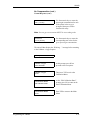
Edit Calibration Data?
The Edit Calibration submenu contains the following two options:
•
Enable Compensation (for Pressure and Background)
•
No Compensation (for Normal or Damped Response)
Note: Normal response may NOT be used in conjunction with either
pressure or background compensation.
CALIBRATION MENU
Edit Calibration Data?
At the “Edit Calibration Data?”
prompt, press YES to enter the
Enable Compensation option.
Proceed to the appropriate section to either enable compensation or
select no compensation.
To Enable Compensation:
Enable Compensation:
[YES]
no
Use the NO or arrow keys to select
YES. Press YES to confirm the
entry and enter the Select
Compensation option.
The Select Compensation option allows the user to calibrate for either
pressure or background compensation; proceed to the following
sections for a description of each choice.
4-30
Programming the TMO2D
9/30/93
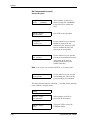
Edit Calibration Data?
(cont.)
To Calibrate for Pressure Compensation, the user must enter both
transducer data and pressure grid data:
Select Compensation:
[PRES]
bkgd
Use the NO or arrow keys to select
PRES, then press YES to confirm
the entry.
Calibrate - Pressure
Transducer Data?
Press YES again to enter
transducer data.
Pressure Curve Entry
# of Points [ 2 ]:
Use the numeric keys to enter the
number of points in the pressure
transducer curve, then press YES
to confirm the entry.
Point #1
mmHg [ XXX.X ]:
Press YES again to enter the
pressure in mmHg for the given
point in the transducer curve.
Point #1
mmHg [ 767.3 ]:
Use the numeric keys to enter the
value, then press YES to confirm
the entry.
Point #1
P mA [ X.XX ]:
Press YES again to enter the
corresponding mA value for the
given point in the transducer
curve.
Point #1
P mA [ 9.17 ]:
Use the numeric keys to enter the
value, then press YES to confirm
the entry.
Repeat the procedure for each point in the transducer curve. The unit
will then display the “Working” message before returning to the
Calibrate - Pressure option.
Working . . .
Programming the TMO2D
.
4-31
9/30/93
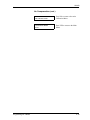
Edit Calibration Data?
(cont.)
Calibrate - Pressure
Transducer Data?
Press NO to proceed to the Enter
Grid Data option.
Calibrate - Pressure
Enter Grid Data?
Press YES to enter grid data.
Pressure Grid Entry
# of Curves [ 2 ]:
Use the numeric keys to enter the
number of curves in the pressure
calibration grid, then press YES
twice to confirm the entry and
proceed to the next prompt.
Curve #1
mmHg [ 760.0 ]:
Use the numeric keys to enter the
pressure in mmHg for each of the
curves in the pressure grid, then
press YES twice to confirm the
entry and proceed to the next
prompt.
Note: Be sure to repeat the procedure for each curve number.
Pressure Grid Entry
# of Points [ 2 ]:
Use the numeric keys to enter the
number of points in the pressure
grid, then press YES twice to
confirm the entry and proceed to
the next prompt.
Point #1
O2 [XX.X]:
Use the numeric keys to enter the
percent gas concentrations for each
of the points in each curve as
prompted, then press YES to
confirm the entry.
Note: Percent gas concentrations MUST be in ascending order.
4-32
Programming the TMO2D
9/30/93
Edit Calibration Data?
(cont.)
XX.X %O2, XXX.X mmHg
Enter Point? yes [NO]
At this prompt, select YES to enter
the calibration data for the given
point, or select NO to have the unit
determine the value for the given
point.
Note: Each curve must have AT LEAST TWO entered data points.
XX.X %O2, XXX.X mmHg
Enter Point? [YES] no
To enter the calibration data, use
the NO or arrow keys to select
YES, then press YES to confirm
the entry.
XX.X %O2, XXX.X mmHg
O2 mA [ X.XX ]:
Use the numeric keys to enter the
corresponding milliamp value for
the given point.
Repeat the procedure for every point in the pressure grid. The unit
will then display the “Working. . .” message before returning to the
Calibrate - Pressure option.
Working . . .
Programming the TMO2D
Calibrate - Pressure
Enter Grid Data?
At this prompt, press NO to
proceed to the next option.
Calibrate - Pressure
Done?
Then press YES to return to the
Calibration Menu.
CALIBRATION MENU
Edit Calibration Data?
At the “Edit Calibration Data?”
prompt, press YES to enter the
Enable Compensation option.
4-33
9/30/93
Edit Calibration Data?
(cont.)
To Calibrate for Background Compensation, the user must enter
background grid data.
Enable Compensation:
[YES]
no
At this prompt, use the NO or
arrow keys to select YES, then
press YES again to confirm the
entry.
Select Compensation:
pres
[BKGD]
Use the NO or arrow keys to select
BKGD, then press YES to confirm
the entry.
Calibrate - Background
Enter Grid Data?
Press YES again to enter grid data.
O2 Grid Entry
# of Curves [ 2 ]:
Use the numeric keys to enter the
number of curves in the
background grid, then press YES
twice to confirm the entry and
proceed to the next prompt.
O2 Grid Entry
# of Points [ 2 ]:
Use the numeric keys to enter the
number of points, then press YES
twice to confirm the entry and
proceed to the next prompt.
Point #1
O2 [XX.X]:
Use the numeric keys to enter the
percent gas concentrations for each
of the points in each curve as
prompted, then press YES to
confirm the entry.
Note: Percent gas concentrations MUST be in ascending order.
X.XX %O2, Curve #1
Enter Point? yes [NO]
At this prompt, select YES to enter
the calibration data for the given
point, or select NO to have the unit
determine the value for the given
point.
Note: Each curve must have AT LEAST TWO entered data points.
4-34
Programming the TMO2D
9/30/93
Edit Calibration Data?
(cont.)
X.XX %O2, Curve #1
Enter Point? [YES] no
To enter calibration data, use the
NO or arrow keys to select YES,
then press YES to confirm the
entry.
XX.XX %O2, Curve # 1
O2 mA [ X.XX ]:
Use the numeric keys to enter the
corresponding gas input milliamp
value for the given point, then
press YES to confirm the entry.
XX.XX %O2, Curve # 1
Comp mA [ X.XX ]:
Use the numeric keys to enter the
corresponding comp input
milliamp value for the given point.
Repeat the procedure for every point in the background grid. The unit
will then display the “Working. . .” message before returning to the
Calibrate - Background option.
Working . . .
Programming the TMO2D
Calibrate - Background
Enter Grid Data?
At this prompt, press NO to
proceed to the next option.
Calibrate - Background
Done?
Press YES to return to the
Calibration Menu.
4-35
9/30/93
No Compensation:
The second option in the Edit Calibration Data submenu is No
Compensation (for Normal or Damped Response). Refer to page
4-30.
Proceed to the following sections for NORMAL or DAMPED
response.
CALIBRATION MENU
Edit Calibration Data?
At this prompt, press YES to enter
the Enable Compensation option.
Enable Compensation:
yes
[NO]
Use the NO or arrow keys to select
NO.
Set System Response:
normal
[DAMPED]
Press YES to confirm the entry and
enter the Set System Response
option.
Note: Normal response may NOT be used in conjunction with either
pressure or background compensation.
(Refer to page 4-39 for Damped Response).
Normal Response:
4-36
Set System Response:
[NORMAL]
damped
At this prompt use the NO or
arrow keys to select “NORMAL,”
then press YES to confirm the
entry.
Calibrate - Oxygen
Enter Grid Data?
Press YES to enter grid data.
O2 Grid Entry
# of Points [ 2 ]:
Use the numeric keys to enter the
number of points in the gas
calibration curve, then press YES
twice to confirm the entry and
proceed to the next prompt.
Programming the TMO2D
9/30/93
No Compensation (cont.)
Normal Response (cont.)
Point #1
%O2 [ XX.XX ]:
Use the numeric keys to enter the
percent gas concentrations for each
of the points in the curve as
prompted, then press YES to
confirm each entry.
Note: Percent gas concentrations MUST be in ascending order.
XX.XX %O2
O2 mA [ XX.XX ]:
Use the numeric keys to enter the
corresponding mA values for the
given percent gas concentration.
The unit will then display the “Working. . .” message before returning
to the Calibrate - Oxygen option.
Working . . .
Programming the TMO2D
Calibrate - Oxygen
Enter Grid Data?
At this prompt, press NO to
proceed to the next option.
Calibrate - Oxygen
Done?
Then press YES to exit to the
Calibration Menu.
CALIBRATION MENU
Edit Calibration Data?
At the “Edit Calibration Data?”
prompt, press NO to return to the
main Calibration Menu.
CALIBRATION MENU
Done?
Press YES to return to the Main
Menu.
4-37
9/30/93
No Compensation (cont.)
Damped Response:
Set System Response:
normal
[DAMPED]
At this prompt, use the NO or
arrow keys to select “DAMPED,”
then press YES to confirm the
entry.
Calibrate - Oxygen
Enter Grid Data?
Press YES to enter grid data.
O2 Grid Entry
# of Points [ 3 ]:
Use the numeric keys to enter the
number of points in the gas
calibration curve, then press YES
twice to confirm the entry and
proceed to the next prompt.
Point #1
%O2 [ XX.XX ]:
Use the numeric keys to enter the
percent gas concentrations for each
of the points in the curve as
prompted, then press YES to
confirm each entry.
Note: Percent gas concentrations MUST be in ascending order.
XX.XX %O2
O2 mA [ XX.XX ]:
Use the numeric keys to enter the
corresponding mA values for the
given percent gas concentration.
The unit will then display the “Working. . .” message before returning
to the Calibrate - Oxygen option.
Working . . .
4-38
Calibrate - Oxygen
Enter Grid Data?
At this prompt, press NO to
proceed to the next option.
Calibrate - Oxygen
Done?
Then press YES to exit to the
Calibration Menu.
Programming the TMO2D
9/30/93
No Compensation (cont.)
Programming the TMO2D
CALIBRATION MENU
Edit Calibration Data?
Press NO to return to the main
Calibration Menu.
CALIBRATION MENU
Done?
Press YES to return to the Main
Menu.
4-39
Chapter 5
Specifications
TMO2 Oxygen Transmitter. . . . . . . . . . . . . . . . . . . . . . . . . . . . . . . . 5-1
TMO2D Display Specifications . . . . . . . . . . . . . . . . . . . . . . . . . . . . 5-2
1/20/97
TMO2 Oxygen
Transmitter
Measuring Ranges:
0-1% O2,0-2% O2, 0-5% O2,
0-10% O2, 0-25% O2, 0-100% O2
Measurement Resolution: 0.01% O2
Accuracy: 1% of span
Linearity: 0.1% of span
Repeatability: 0.2% of span
Drift: Zero and span, 0.8% of span/month
(0-2% O2 range and higher)
1.5% of span/month (0-1% O2 range)
Speed of Response: 4 seconds for
63% of a step change in O2 (with Display)
Ambient Temperature Influence:
Negligible if transmitter is heated at least 5°C (9°F) above highest
ambient temperature
Transmitter Temperature: Controlled to 45°C (113°F)
Atmospheric Pressure Influence: 0.2% of span per mm Hg
(optional pressure compensation available)
Sample Flow Rate Influence:
Less then 1% of span with 50 to 1000 cc/mm, no flame arrestors
(0.1 to 2 SCFH)
Line Voltage Influence: Negligible
Ambient Requirements:
Relative Humidity: 0-100% (non-condensing)
Temperature: -20 to 40°C (-4 to 104°F) higher temperatures available
Sample Requirements:
Flow: 50 to 1000 cc/min (0.1 to 2 SCFH)
Pressure: 20 psig maximum
Power Requirements: 24 VDC, 1A max
Powered by TMO2D electronics
Electrical Output: 0/4-20 mA to TMO2D electronics
Transmitter/Electronics Separation:
300 m (1000 ft) maximum shielded cable not required
Physical Characteristics:
Dimensions (H x W x D):
143 x 152 x 235 mm
(5.625 x 6 x 9.25 inches)
Weight: 4.3 Kg (9.5 lbs)
Specifications
5-1
1/20/97
TMO2 Oxygen
Transmitter (cont.)
Connections:
3/4-in. NPTF (electrical conduit)
1/4-in. NPTF (sample inlet & outlet)
Area Classification:
Explosion-proof/weatherproof
INIEX Cert. # 90C. 103.882 to
CENELEC EEx d IIC T6
TMO2D Display
Specifications
Performance
Accuracy:
±0.1% of span (electronics only)
Ambient Temperature Effect:
±0.01% of full scale per °C
Functional
Analog Output:
Standard: Single, isolated 0/4-20 mA, 500 ohm maximum, field
programmable
Optional: Dual, isolated 0/4-20 mA, 500 ohm maximum, field
programmable
Alarms:
Standard: Two Form C, SPDT, 2 A max. @117 VAC, field
programmable, 0.01% set-point resolution, 0.05 % of span dead band
Optional: Two hermetically-sealed relays for Class I, Div. 2
hazardous areas, 2 standard or hermetically-sealed relays for
automatic calibration (Auto Cal)
Digital Output: RS-232C serial port
Display: 2-line x 24 character backlit LCD
Analog Input: 4 to 20 mA from TMO2-TC Transmitter
Power:
100/120/220/240 VAC +/- 10%, 50/60 Hz, 35 watts max., provides 24
VDC, 1 A max. to TMO2-TC Transmitter
Fuses:
110/120 VAC: 0.5 A, Slo-Blo.
220/240 VAC: 0.25 A, Slo-Blo.
Temperature:
Operating: 0 to +50°C (+32 to +122 °F)
Storage: -20 to +70°C (-4 to +158°F)
5-2
Specifications
1/20/97
Physical
Dimensions:
Rack Mount: 5.25" (H) x 19" (W) x 9.25" (D)
(133 x 483 x 235 mm)
Bench Mount:5.25" (H) x 9" (W) x 9.25" (D)
(133 x 229 x 235 mm)
Panel Mount:5.25" (H) x 9" (W) x 9.25" (D)
(133 x 229 x 235 mm)
Weatherproof, fiberglass: 11.25" (H) x 9.38" (W) x 4.38" (D)
(286 x 238 x 111 mm)
Weatherproof, stainless steel: Consult factory
Explosion-proof: Consult factory
Weight:
Rack Mount: 5.4 lbs (2.4 kg)
Bench Mount: 7.4 lbs (3.4 kg)
Panel Mount: 4.7 lbs (2.1 kg)
Weatherproof, fiberglass: 6.5 lbs (3.0 kg)
Weatherproof, stainless steel: Consult factory
Explosion-proof: Consult factory
Environmental:
Rack, Bench, Panel Mount: General-purpose
Weatherproof, fiberglass: NEMA-4X; IP65
Weatherproof, stainless steel: Consult factory
Explosion-proof: Consult factory
European Compliance:
This unit complies with EMC Directive 89/336/EEC and 73/23/EEC
Low Voltage Directive. (Installation Category II, Pollution Degree
II.)
Specifications
5-3
Appendix A
Thermoparamagnetic (Magnetic Wind) Theory
Basic Principle . . . . . . . . . . . . . . . . . . . . . . . . . . . . . . . . . . . . . . . . A-1
The TMO2 Transmitter Oxygen Measurement Bridge. . . . . . . . . A-1
The TMO2 Transmitter Compensation Bridge . . . . . . . . . . . . . . . A-2
TMO2D Electronics Microprocessor-based Compensation for
Variations in Background Gas Composition . . . . . . . . . . . . . . . . A-2
4/8/92
Basic Principle
Since its magnetic susceptibility is approximately 100 times greater
than most common gases, oxygen can be easily distinguished from
other gases based on its attraction into a magnetic field. The
magnetic susceptibility of oxygen varies with temperature — more
strongly attracted at low temperatures, and less at high temperatures.
Therefore, by carefully combining a magnetic field gradient and a
temperature gradient with the TMO2 transmitter measuring cell, an
oxygen-containing gas can be made to flow, creating "magnetic
wind." The intensity of this induced flow depends on the
concentrations of oxygen in the sample.
The TMO2 Transmitter
Oxygen Measurement
Bridge
In the TMO2 transmitter measuring cell, permanent magnets are used
to create a magnetic field. The temperature within the measuring cell
is controlled to a constant 113° (45°C) to maintain thermal
equilibrium. The cell also contains two pairs of thermistors, with one
thermistor of each pair located within the magnetic field. Since the
thermistors are electrically heated, a temperature gradient is created
within the magnetic field.
When a small sample of oxygen-containing gas diffuses into the
measuring cell, it is attracted to the field, causing the sample pressure
to become locally higher. The sample pressure is slightly lower in the
vicinity of the thermistors because the gas is less strongly attracted at
higher termperatures. This difference in sample pressure causes the
gas to flow out from the center of the magnetic field and over the
thermistors. The inner, wind generating thermistors decrease in
temperature as they lose heat to the magnetic wind, while the outer,
wind receiving thermistors increase in temperature as they pick up
heat from the magnetic wind.
The thermistor pairs are additively connected in an electronic
measuring bridge circuit. The circuit is unbalanced as the electrical
resistance of the thermistors change with temperature. The circuit
imbalance causes a voltage to appear across the bridge which is
proportional to the oxygen concentration in the gas being measured.
(See Figure A-1 on the following page.)
Thermoparamagnetic (Magnetic Wind) Theory
A-1
4/8/92
Figure A-1: The TMO2 Oxygen Transmitter
The TMO2 Transmitter
Compensation Bridge
As the background gases which make up the balance of an oxygencontaining mixture change, the thermal and magnetic properties
change and affect heat transfer to and from the thermistors. This is
ultimately reflected in thermistor temperature, and will affect oxygen
measurement if left uncompensated.
For this reason, the TMO2 transmitter features a unique "bridgewithin-a-bridge-circuit." The oxygen measuring bridge described
above is one arm of yet another compensation bridge which maintains
the oxygen bridge at a constant temperature regardless of variations
in background gas compensation.
TMO2D Electronics
Microprocessor-based
Compensation for
Variations in
Background Gas
Composition
A-2
By sensing the compensation bridge current necessary to restore
oxygen bridge temperature, a signal is obtained which is transmitted
to the TMO2D electronics where microprocessor-based background
gas compensation is performed.
Thermoparamagnetic (Magnetic Wind) Theory
Appendix B
Outline and Installation Drawings
TMO2 Outline and Installation (Dwg. #712-211). . . . . . . . . . . . . . B-1
TMO2D Rack Model Outline and Installation (Dwg. #421-255) . . B-2
TMO2 Oxygen Analyzer Assembly (Dwg. #705-468) . . . . . . . . . . B-3
PCB Analyzer Assembly (Dwg. #703-1036) . . . . . . . . . . . . . . . . . B-4
TMO2D Top Assembly (Dwg. #705-517, sh. 2) . . . . . . . . . . . . . . . B-5
Analyzer PCB Schematic (Dwg. #700-1036). . . . . . . . . . . . . . . . . B-6
Oxygen Analyzer Display PCB Assembly (Dwg. #703-1226) . . . B-7
Oxygen Analyzer Display PCB Schematic (Dwg. #700-1226, sh. 1)
B-8
Oxygen Analyzer Display PCB Schematic (Dwg. #700-1226, sh. 2)
B-9
Oxygen Analyzer Display PCB Schematic (Dwg. #700-1226, sh. 3)
B-10
Figure B-1: TMO2 Outline and Installation (Dwg. #712-211)
1/20/97
B-1
1/20/97
',$
+2/(6
57<3
a
5()
6((127(
127(6
0$7(5,$/7+.7$/80,180$//2<
),1,6+&/($5,5,',7(
5(029($//%85566+$53('*(6
)5217685)$&(72%()5((2)$//6&5$7&+(6
%/(0,6+(6$1'722/0$5.6
3$,17)5217685)$&($//('*(6'$5.*5$<
&2/253(5)('67'
6(0,*/266&/($5(32;<723&2$7
5
7<33/$&(6
7<3
%27+(1'6
Figure B-2: TMO2D Rack Model Outline and Installation (Dwg. #421-255)
B-2
Figure B-3: TMO2 Oxygen Analyzer Assembly (Dwg. #705-468)
1/20/97
B-3
'212775,0/($'6
6$
5
( 5
2
3
(1
5
&
2
0
3
*
$
,1
$
'
-
(
(
2
)
)
6(
7
9
2
/7
$
*
(
(
(
9
5
(
)
(
(
( (
&
&
5
5
55
5
5
&
2
0
3
2
)
)
6
(
7
$
'
-
5
95
5
&& 5
8
5
$
5
$
5
8; 5 5 5 $
8 :
8
5 ;
8
5
(
(
9
5
(
)
5
5
5
55
(
5 5
5
5
5
9
5
&
8 &
5
$
&
&
5
5
5
3 5
5
59&
55
45
5
&
4
;
88
( 5
&
5 5$ &
5
/2
&
5
$
&5
5
5
8 ;8
4
-
+
,
;8 8
&
5 5
7%
&
4
;
88
&
(
5
4
&
5
5
$
&
(
(
5
2
*
$
,1
$
'
-
6
*
$
,1
6
:
,7
&
+
( 5
$
6
8
;
8
&
(
9
3
,167$//21
/2326,7,21
(2;<*(16,*1$/
Figure B-4: PCB Analyzer Assembly (Dwg. #703-1036)
6 6 6 6 6 6
$ $ $ $ $ $
$ 0 & ,1 ' 8 29 ' / 0( 9
,7 7,3 3 5 9 5
,9 / 6( 5 (
( ,& $ ( )
& 77 & )
$
2
2 7, (
1 0
09
8 3
3 (
& $
7
2(
0
3
5
95
0
7
(
(
(
5 &
7%
$
7%
%
&
7%
&
2
0
3
5
5
(
8
5()
5
5
&
7%
2
4
5()
5
5
5
=
(
5
2
$
'
-
(
&
2
0
3
,
1
3
8
7
( (
5
7
1
9
7%
5
71
7%
9
,1
1/20/97
7+,6'5$:,1*,6$)$&725<0878$/5(6($5&+
$33529(''(6,*112&+$1*(,63(50,77('
81/(66$87+25,=('%<)$&725<0878$/
3
5()
B-4
Figure B-5: TMO2D Top Assembly (Dwg. #705-517, sh. 2)
1/20/97
B-5
0
7
8
% & (
$ 2 0
6
( // ,77
(
( 5
&
72
5
9
9
2 5 ,1
8 71
7 &
$
6
(
' * 6
5 $ 2
$ 7 8
,1 ( 5
&
(
$ & 1
1 $ 2
2 7+ &
' 2 2
( '
( 1
1
%
2
77
2
0
9
,(
:
6
%$
6(
'
,$
*
5
$
0
6
#8
#8
#8
#8
#8
#8
9
#8
&
&
&
&
&
&
$
57
1
%5
71
3 -
.
&
&
&
&
&
&
&
.
5$
.
2
37
,2
1
9$
/8
(
2
37
,2
16
2
37
,2
1
*
5
2
2 836
87
38
7
*
$6
&
2
0
3
;0
7
5
5(
)'
(6
:
7$
%/
(
7$
%/
(
5
0
$<
%
(5
(0
2
9(
'
'8
5,
1*
&
$/
,%5
$7
,2
1
35
2
&(
'8
5(
$
57
1
5$
&
$3
$&
,72
5
9$
,1 /8(6
', $
&$ 5
7( ((
60 ;3
$5 (56
.1, 6(
* ',1
0
,&
52
)$
5$
'6
9
8
1/
(6
62
7+
(5
:
,6(
63
(&
,),
('
/)
5$
.
5$
5
.
81
/(
66
2
7+
(5
:
,6(
63
(&
,),
('
8
5$
$
;,$
//
($
'
5(
6,6
72
5
9$
/8
(6
$
5(
(
;3
5(
66
('
,1
2
+0
6
5
1
8
1/
(6
62
7+
(5
:
,6(
63
(&
,),
('
12
78
6(
'
5(
)'
(6
5
$
57
1
12
7(
6
8
(
7/
(
&
95
.
8
5$
%5
71
7/
(
&
&
57
1
%5
71
$
57
1
$
57
1
.
$
57
1
$
57
1
9
5(
)
57
1
.
(
5$
5
5
.
&:
&
1
&5
3
5
(6
68
5
(
&
2
0
3
(1
6$
7,
2
1
9
5
.
5
.
5
5
&
*2
$, 0
13
.
.
(
$
57
1
$
57
1
35
(6
68
5(
6
(1
62
5
$
57
1
8
7%
%
7%
7% $
/0
9 7
92
87
9,
1
9,1
2 &2
)) 0
6( 3
7
57
1
&:
&
&
5
$
.
9
9
(
7+,6,6$)$&725<0878$/5(6($5&+$33529('
'(6,*1$1'12&+$1*(,63(50,77('
81/(66$87+25,=('%<)$&725<0878$/
.
$
57
1
.
5
5
5(
)
6(
/(
&
7
8
,1
.
/)
6$
'
/)
.
6
5$
8
(
5$
$
57
1
.
.
.
5$
(
.
.
*
6
,1
9
5
5$
5$
.
5$
(
2
87
5$
6$
0
7
8
8
.
5
5
7/
(
&
.
4
*
5
.
5$
.
.
8
8
93
1
.
/)
,1
/)
$
77
(1
8$
7(
6$
5$
5$
&
2
0
03
$
.
.
95
()
5$
6$
5$
9
5(
)
.
/)
*
6
5
2
87
(
9
9
$
57
1
5$
.
5$
8
8
7/
(
&
/)
5
$
57
1
:
51 &
5
&
5
+
5
(
%/
.
0
-(
-
3
6$
$
57
1
+
5
(
.
&
63
(&
,$
/6
&
57
1
.
57
5
5
(
.
8
.
5
5
5
$
57
1
5
2
0
$
6(
(
7$
%/
(
8
5
57
93
1
4
6
5$
/)
$
57
1
8
5
9
9
2
3
(
8
3
-
3
-
(
5
&
:
5
:
+
7
(
.
*
5
.
9
(
57
&:
&:
.
5
/)
(
9
.
.
(
8
5
5
5
&
:
.
5
57
.
5
9
5
(
.
%5
71
&
5$
5
9
5
3
-
.
%5
,'
*
(
92
/7
$
*
(
-
3
,2
3 $
&
%
2
*
$,
1
5
95
5
(
7(
$
66 0
(0 33 $
5 /%< 2
%(
6(
/(
&
7
/2
/0
9 %
=
4
(
+
,
0
-(
5
9
5$
5
7
9
.
5$
5 =
(5
2
$
57
1
95
()
7%
$
7%
7% %
'
5
.
5
,
2
$
3& %
(
(
.
(
95
1
9 $
95
2
(
6& ( & & ( )
$$% %
< < ; ; 9
&
&
0
3
9
= <
2
6 $
9
2&
&
= 78 5$
.
.
5$ 2
;< $
*
(1
,
2
$
3& %
95
5
/0
9 %=
(
5
5$
5
57 & 1 ,1
, 99
/6 &
/6
,1
.
(
51
'
3
-
$
57
1
6' & &
27
0
57 3
1 /0
5$
$
$
66 1
(0 $
/
%/ <=(
< 5
8
/)
&
.
&
5
12 53
7 (6
$6 ( 6
$
57
1
3
-
(
4
6: &
,7& 2
0
+ 3 [
2
;<
$
66 *
(0 (1 $
% 6(
</ 1
62
5
,
2
$
3& %
5$
9
.
(
&
57
1
&
57
1
(
%5
71
%5
71
3)
9
9
.B
9
Figure B-6: Analyzer PCB Schematic (Dwg. #700-1036)
$
57
1
/0
9 %
7$
%/
(
95
()
8186('
35
(6
6&
2
0
3
. .
.
5 5 5
67
$1
'$
5'
$
57
1
9
(9 +
( 7 8 9 & 4 & 5 5 (5 ,*
3 - 0
7 6$ :
% 5 5 $ 86 +(6
(' 7
$
571
%
571
&
571
9
9
9
7/(
0 / /0 / / 7 ,& 7$
7 0 < 32 %/
/) 3< 2
3 )
(
3( :
(5 & $
8 8 8 8 8 8 8 8 5()
'
(6
4
7<
4
8
4
95
(
5
.
,2
3 $
& %
5
5(
'
&
&
-
3
-
3
%5
71
5 6: * 6
$
. ,7& $
+ ,1
9
&
1
2
3
.
4
8
8
5$
(
(
%5
71
9&
&
9
5(
)
&
&
2
&
6&
/7
57
1
92 )%
87
.
9
(
&
9 9
1/20/97
B-6
Figure B-7: Oxygen Analyzer Display PCB Assembly (Dwg. #703-1226)
1/20/97
B-7
Figure B-8: Oxygen Analyzer Display PCB Schematic (Dwg. #700-1226, sh. 1)
1/20/97
B-8
Figure B-9: Oxygen Analyzer Display PCB Schematic (Dwg. #700-1226, sh. 2)
1/20/97
B-9
Figure B-10: Oxygen Analyzer Display PCB Schematic (Dwg. #700-1226, sh. 3)
1/20/97
B-10
Appendix C
RS-232C Serial Port
4/8/92
RS-232C Serial
Port
The TMO2D contains a bidirectional, industry standard RS-232C serial
port which can be connected to a terminal or computer that supports the
RS-232C protocol (see Chapter 4, page 4-6).
All keypad and most display operations can be performed remotely
through this serial port.
Table C-1 below provides an illustration of the terminal/computer keys
and how they correspond to the keys on the display keypad.
[1]
031
"1"
RS-232C Serial Port
Table C-1: TMO2D RS-232C Serial Port
and Corresponding Keys
[4]
[7]
[-]
034
037
02D
"4"
"7"
"-"
[2]
032
"2"
[5]
035
"5"
[8]
038
"8"
[0]
030
"0"
[3]
033
"3"
[6]
036
"6"
[9]
039
"9"
[.]
02E
"."
[Y]
00D
ENTER
[N]
01B
ESCAPE
[←]
008
BACKSPACE
[→ ]
020
SPACE
C-1
Appendix D
The TMO2 Transmitter Calibration Procedure
Introduction . . . . . . . . . . . . . . . . . . . . . . . . . . . . . . . . . . . . . . . . . . D-1
Equipment and Drawings . . . . . . . . . . . . . . . . . . . . . . . . . . . . . . . D-2
Setup . . . . . . . . . . . . . . . . . . . . . . . . . . . . . . . . . . . . . . . . . . . . . . . . D-3
Preliminary Explanation . . . . . . . . . . . . . . . . . . . . . . . . . . . . . . . . D-3
Internal Background Gas Compensation. . . . . . . . . . . . . . . . . . . D-5
External Compensation . . . . . . . . . . . . . . . . . . . . . . . . . . . . . . . . . D-6
Internal Pressure Compensation . . . . . . . . . . . . . . . . . . . . . . . . . D-7
External Pressure Signal Calibration . . . . . . . . . . . . . . . . . . . . . . D-8
Internal Hydrogen Gas Compensation. . . . . . . . . . . . . . . . . . . . . D-9
External Hydrogen Gas Compensation . . . . . . . . . . . . . . . . . . . . D-9
Internal Methane Gas Compensation (Reverse Compensation) D-9
1/20/97
Introduction
Factory calibration procedures are included here for reference only.
Do not attempt factory calibration in the field. For field calibration,
refer to the TMO2D calibration sheet that was shipped with your unit.
!WARNING!
TO ENSURE THE SAFE OPERATION OF THE
TMO2D, YOU MUST INSTALL AND OPERATE IT AS
DESCRIBED IN THIS MANUAL. IN ADDITION, BE
SURE TO FOLLOW ALL APPLICABLE SAFETY
CODES AND REGULATIONS FOR INSTALLING
ELECTRICAL EQUIPMENT IN YOUR AREA.
The TMO2 Transmitter Calibration Procedure
D-1
11/30/92
Equipment and
Drawings
Test Equipment:
•
Two 3-1/2 digit DVMs, HP 3438A or equivalent
•
Pressure generator 0-1 PSI
TMO2 Equipment:
•
Completely assembled TMO2 oxygen analyzer
Sample Gas Equipment:
•
Cylinder of 100% oxygen with regulator
•
Cylinder of primary background gas (Gas A)
•
Cylinder of secondary background gas (Gas B)
•
Sample system to control/combine the above gasses
Drawings:
D-2
•
705-468, TMO2 Top Assembly
•
703-1036, Assembly, Analyzer PCB
•
700-1036, Schematic, Analyzer PCB
•
712-211, Outline and Installation
The TMO2 Transmitter Calibration Procedure
11/30/92
Setup
1. Connect gas inlet of the TMO2 transmitter to the sample system.
2. Connect 0-20 milliamp meter to TB1 of transmitter: pin 3 (+) and
pin 2 (return).
3. Connect +24 VDC power supply to TB1 of the transmitter PCB.
Connect the positive terminal to pin 1 and the negative terminal to
pin 2 of the TB1. Turn on power and let transmitter warm up for at
least 30 minutes.
Preliminary
Explanation
The following procedures describe how to calibrate various TMO2
oxygen analyzers. Most analyzers have internal background gas
compensation to correct the output for changes in the gas
composition. To begin, the compensation will be fixed (to 2.00v),
while the oxygen circuit is calibrated using zero and span (ex. 0% and
10%) oxygen. The primary background gas, referred to as Gas A, will
compose the remainder of the mixture.
Next, the compensation circuit is calibrated. In this procedure, the
TMO2 transmitter is exposed to full scale oxygen (ex. 10%) in a
background of Gas A followed by full scale oxygen in Gas B, the
secondary background gas.
The type of gases used for Gas A and Gas B will vary depending on
the application. As an example, the calibration for a customer who
uses the TMO2 to measure oxygen in a hydrogen tank would use
hydrogen as Gas A. Nitrogen might be used for Gas B, since a system
leak would inject air/nitrogen into the mixture.
In addition, circuits can be added to the analyzer board to provide
pressure compensation, reverse compensation, and compensation
attenuation. These options are switch selectable at calibration to
provide proper compensation for hydrogen/helium, methane and
pressure sensitive applications.
Swich SA1 on the circuit board is used to select the following six
operating functions:
•
SA1 - 1: Selects negative offset voltage
•
SA1 - 2: Selects positive offset voltage
•
SA1 - 3: Selects inverse compensation
•
SA1 - 4: Selects compensation attenuation
•
SA1 - 5: Selects multiplying compensation
•
SA1 - 6: Selects additive compensation
The TMO2 Transmitter Calibration Procedure
D-3
11/30/92
Preliminary
Explanation (cont.)
Zero adjustments are made via R20, R29, and R44. When properly
adjusted, zero shift errors due to background gas changes can be
reduced.
Oxygen signal gain is controlled by rotary switch (S1) and R41. S1
serves as a course gain conrol while R41 provides fine gain
adjustment. Rotating either control in the clockwise direction
provides increased gain.
Note: Do not use the “0" position on S1.
R27 and R28 provide the offset and gain adjustments for the
compensation circuits.
High or low bridge voltage is selected via jumper plug J3. Low
voltage should be used for most applications. High voltage is used
with hydrogen and helium background gasses.
Most analyzers will be magnetized and marked as high (H), medium
(M), or low (L) assemblies. The oxygen ranges that can be calibrated
for each type of magnetization are:
D-4
Magnetization
O2 Range
High (H)
0- 1, 2, 5, 10, 21%
Medium (M)
0- 25%, 95-100%
Low (L)
0- 100%
The TMO2 Transmitter Calibration Procedure
11/30/92
Internal Background
Gas Compensation
Internal Background gas compensation is used to provide a single 0/
4-20 milliamp oxygen signal that is constant despite changes in the
gas composition.
Note: In the following procedure, the gas mixture having the largest
oxygen sensitivity should be used as Gas A.
Set SA1 switches as follows: 1, 3, 4 & 6 = OFF (up position)
2 & 5 = ON
Set J3 to the LO position (HI if using hydrogen/helium).
Zero:
1. Set S1 to position 9 and adjust R41 fully clockwise.
2. Apply background Gas A (ex. 100% CO2) into the oxygen
transmitter.
3. Adjust R27 until the voltage at E14 equals +2.0 volts.
4. Adjust R28 until the voltage at E10 equals +2.0 volts.
5. Turn R20 fully clockwise.
6. Adjust R29 until TB1-3 is 0/4 milliamps.
7. Turn R20 fully counter-clockwise.
8. Adjust R44 until TB1-3 is 0/4 milliamps.
9. Repeat steps 5 through 8 as required.
10.Apply background Gas B (ex. 100% N2) into the oxygen
transmitter.
11. Adjust R20 until the output is 0/4 milliamps.
12.Reapply Gas A and fine tune R29 for 0/4 milliamps output.
The TMO2 Transmitter Calibration Procedure
D-5
11/30/92
Span Compensation:
1. Apply span/background Gas A (ex. 10% oxygen, remainder CO2)
into the oxygen transmitter.
2. Adjust S1 and R41 until the output is 20 milliamps.
3. Apply span/background Gas B (ex. 10% oxygen, remainder N2)
into the oxygen transmitter.
4. Adjust R28 until the output is 20 milliamps.
5. Reapply span/background Gas A (ex. 10% oxygen, remainder
CO2) into the oxygen transmitter.
6. Adjust R27 until the output is 20 milliamps.
7. Repeat steps 3 through 6 until a consistent output is obtained.
Note: R27 and R28 are interdependent; adjustment of one pot will
affect the setpoint of the other pot.
External
Compensation
A TMO2 transmitter with external compensation provides a separate
0-20 mA output to indicate the relative thermoconductivity of the gas
mixture. In normally compensated transmitters this signal is
internally multiplied by the internal oxygen signal to give a single
compensated oxygen 0/4-20 mA output. In externally compensated
transmitters, however, one output is an uncompensated oxygen signal
(TB1, pin 3) and the second output represents thermoconductivity
(TB1, pin 4). These signals may then be used in a TMO2D algorithm
to provide an improved oxygen calculation.
Note: In the following procedure, the gas mixture having the largest
oxygen sensitivity should be used as Gas A.
Set SA1 switches as follows: 1, 3, 5 & 6 = OFF (up position)
2 & 4 = ON
Set J3 to the LO position (HI if using hydrogen/helium).
Zero:
Refer to page D-5, Zero, and follow steps 1 through 12, but set E14 to
+0.30 volts in step #3 and disregard step #4.
Oxygen Span:
1. Apply span/background Gas A (ex. 10% oxygen, remainder CO2)
into the oxygen transmitter.
2. Adjust S1 and R41 until the TB1-3 is about 20 milliamps.
D-6
The TMO2 Transmitter Calibration Procedure
11/30/92
External Compensation:
1. Apply background Gas B (ex. 100% Hydrogen) into the oxygen
transmitter.
2. Adjust R28 until TB1-4 is about 20 milliamps.*
3. Apply background Gas A (ex. 100% CO2) into the oxygen
transmitter.
4. Adjust R27 until the TB1-4 is about 4 milliamps.*
5. Repeat steps 1 through 4 until the desired outputs are acquired.
*These values are arbitrary and may vary somewhat since they will
be entered into TMO2D or System 1 calibration tables. The levels
should extend from 1 to 35 milliamps, taking all expected gas
mixtures into account.
Note: R27 and R28 are interdependent; adjustment of one pot will
affect the setpoint of the other pot.
Internal Pressure
Compensation
The analyzer circuit board can accommodate three types of pressure
compensation: Additive, Multiplicative, and External. Additive and
multiplicative pressure compensation are performed on the analyzer
circuit board, whereas external pressure compensation produces an
auxiliary 4-20 (TB1-4) milliamp signal for use in TMO2D
compensation calculations.
This section describes additive and multiplying pressure
compensation. Additive pressure compensation is used to make
corrections on 100% oxygen analyzers. Multiplying should be used
on the lower oxygen ranges. Calibration of the auxiliary external
pressure signal is covered in the next section.
Additive Comp: Set SA1 switches as follows: 1, 4 & 5 = OFF (up)
2, 3 & 6 = ON
Multiplying Comp: Set SA1 switches as follows: 2, 3 & 6 = OFF
1, 4 & 5 = ON
Set J3 to the LO position (HI if using hydrogen/helium).
The TMO2 Transmitter Calibration Procedure
D-7
11/30/92
Zero:
Refer to page D-5, Zero, and follow steps 1 through 12, setting E14 to
+2.94 volts (additive comp.) or -0.80 volts (multiplying comp.) in
step #3. (With single background gas systems, use only steps 1
through 6.)
Span Compensation:
1. Apply span gas (ex. 100% oxygen) into the oxygen transmitter.
2. Adjust S1 and R41 until the output (TB1-3) is 20 milliamps.
3. Apply span pressure to the pressure sensor (ex. 1.0 PSI).
4. Adjust R28 until TB1-3 is 20 milliamps.
5. Apply minspan pressure to the pressure sensor (ex. 0 PSI).
6. Adjust R27 until TB1-3 is 20 milliamps.
7. Repeat steps 3 through 6 until a consistent output is obtained.
Note: R27 and R28 are interdependent; adjustment of one pot will
affect the setpoint of the other pot.
External Pressure
Signal Calibration
This system uses an analyzer with separate oxygen and pressure
signal outputs. These signals would normally be used by TMO2D
programs to produce a pressure corrected oxygen value.
Set SA1 switches as follows: 1, 4, 5 & 6 =OFF (up)
2 & 3 = ON
Set J3 to the LO position (HI if using hydrogen/helium).
Zero:
Refer to page D-5, Zero, and follow steps 1 through 12, setting E14 to
+2.0 volts in step #3. (With single background gas systems, use
only steps 1 through 6.)
Oxygen Span:
1. Apply span/background gas (ex. 10% oxygen, remainder CO2)
into the oxygen transmitter.
2. Adjust S1 and R41 until the TB1-3 is about 15 milliamps.*
D-8
The TMO2 Transmitter Calibration Procedure
11/30/92
External Pressure
Signal:
1. Apply span pressure to the pressure sensor (ex. 1.0 PSI).
2. Adjust R28 until TB1-4 is approximately 20 milliamps.*
3. Apply minspan pressure to the pressure sensor (ex. 0.0 PSI).
4. Adjust R27 until the output is approximately 10 milliamps.*
5. Repeat steps 1 through 4 until the desired outputs are obtained.
*These values are arbitrary and may vary somewhat since they will
be entered into TMO2D or System 1 calibration tables. The levels
should extend from 1 to 35 milliamps, taking all expected gas
mixtures into account.
Note: R27 and R28 are interdependent; adjustment of one pot will
affect the setpoint of the other pot.
Internal Hydrogen Gas
Compensation
Set SA1 switches as follows: 1, 3, 4 & 6 = OFF (up)
2 & 5 = ON
Set J3 to the HI position (HI if using hydrogen/helium).
Zero:
Refer to page D-5, Zero, and follow steps 1 through 12, but set E14 to
+0.92 volts in step #3, and set E10 to 4.0 volts in step #4.
Span Compensation:
Refer to page D-6, Span Compensation, and follow steps 1 through 7.
External Hydrogen Gas
Compensation
Refer to page D-6, External Compensation, but set J3 to the HI
position.
Internal Methane Gas
Compensation
(Reverse
Compensation)
Set SA1 switches as follows: 2, 4 & 6 = OFF (up)
1, 3 & 5 = ON
Zero:
Refer to page D-5, Zero, and follow steps 1 through 12, setting E14 to
-3.15 volts in step #3.
Span Compensation:
Refer to page D-6, Span Compensation, and follow steps 1 through 7.
Set J3 to the LO position (HI if using hydrogen/helium).
The TMO2 Transmitter Calibration Procedure
D-9
Appendix E
Main Menu Flow Diagrams
Setup and Recorder Menu Flow Diagrams . . . . . . . . . . . . . . . . . E-1
Alarm and Test Menu Flow Diagrams. . . . . . . . . . . . . . . . . . . . . . E-3
Calibration Menu Flow Diagram . . . . . . . . . . . . . . . . . . . . . . . . . . B-1
9/30/93
Figure E-1: Setup and Recorder Menu Flow Diagrams
Main Menu Flow Diagrams
E-1
9/30/93
Figure E-2: Alarm and Test Menu Flow Diagrams
Main Menu Flow Diagrams
E-3
9/30/93
Goes to MAIN MENU "Resume?"
[YES]
[NO]
or
CALIBRATION MENU
Auto Cal Parameters?
[YES]
[NO]
or
Enable AutoCal:
no
[YES]
AUTO CAL MENU
Set Time Interval:
[NO]
Select AutoCal interval:
hours
[DAYS]
[YES]
AutoCal Interval
Days [X]:
Enter the time interval.
{YES], [YES]
AutoCal at Time:
HH.MM. [XX.XX]:
Note: This prompt will not appear if
interval is being entered in hours.
Enter the time AutoCal is to begin
(in 24-hour format).
[YES], [YES]
AUTO CAL MENU
Set Zero Gas?
or
[NO]
Zero Gas
%O2 [X.XX]:
Enter the percentage of oxygen in
the zero calibration gas.
[YES], [YES]
Zero Gas ON for
MM.SS [X.XX]:
Enter the percentage of oxygen in
the zero calibration gas.
[YES], [YES]
AUTO CAL MENU
Set Span Gas?
[YES]
or
[NO]
Span Gas
%O2 [X.XX]:
Enter the percentage of oxygen in the
span calibration gas.
[YES], [YES]
Span Gas ON for
MM.SS [X.XX]:
Enter the equilibration time for
the span gas.
{YES], [YES]
or
[NO]
[YES], [YES]
AUTO CAL MENU
Set Error Handling?
[YES]
or
[NO]
AUTO CAL MENU
Perform AutoCal?
[YES]
or
[NO]
TMO2D automatically calibrates.
Press [NO] to interrupt, otherwise
the unit calibrates and returns to
the "Perform AutoCal?" prompt.
[NO]
[YES]
Use the [NO] or arrow keys to move
the brackets to the desired selection.
Select [YES] or select [NO]
AUTOCAL Error Effects
Set Display Response?
[YES]
or
[NO]
Display AutoCal Error?
[YES]
Select [YES] or select [NO]
AUTOCAL Error Effects
Set Alarm Response?
or
[NO]
Select Alarm Effect:
No Effect?
Trip High?
Trip Low?
Trip Both?
Use the [NO] or arrow keys to
scroll to the desired selection.
[YES]
AUTOCAL Error Effects
Set Recorder Response?
[YES]
[NO]
Abort AutoCal?
Settling . . .
or
[NO]
Select Recorder Effect:
No Effect?
Force High?
Force Low?
Hold Last Value?
Use the [NO] or arrow keys to
scroll to the desired selection.
[YES]
AUTOCAL Error Effects
Done?
[YES] returns to the AUTO CAL MENU
"Set Error Handling?" prompt.
[NO] returns to the AUTO CAL Error
Effects "Set Display Response?"
prompt.
[NO]
[NO] causes the TMO2D to resume
settling then return to the "Perform
AutoCal?" prompt.
AUTO CAL MENU
Zero AutoCal?
or
Use the [NO] or arrow keys to move
the brackets to the desired selection.
Select [YES] or select [NO]
Set System Response:
[DAMPED]
normal
pres
[BKGD]
[YES]
If you select PRES
[NO]
[YES]
or
[NO]
PRES CURVE ENTRY
# of Points [X]:
Enter the number of points.
[YES], [YES]
Point #1
mmHg [X.XX]
Enter the signal value in
millimeters of mercury.
Zero AutoCal?
no
[YES]
Use the [NO] or arrow keys to move
the brackets to the desired selection.
[YES]
Working . . .
[YES], [YES]
Point #1
P mA [X.XX]:
Enter a value for pressure in milliamps.
Note: These two prompts repeat for
each point.
Resets calibration.
AUTO CAL MENU
View Drift Curve?
[YES]
or
Press [YES] to view drift values.
[YES], [NO]
AUTO CAL MENU
Done?
[NO]
[YES] returns to the CALIBRATION
MENU "Auto Cal Parameters?" prompt.
[NO] returns to the AUTO CAL MENU
"Set Time Interval?" prompt.
Enter the number of curves in the
pressure/gas grid.
MAIN MENU
Resume?
Enter the signal for the curve in
millimeters of mercury.
[YES], [YES]
BKGD GRID ENTRY
# of Points [X]:
[NO]
[NO] returns to the CALIBRATION
MENU "Auto Cal?" prompt.
[YES], [YES]
Curve # 1
mmHg [X.X]:
Note: This prompt only appears if you
selected pressure compensation.
or
[YES] returns to MAIN MENU
"Calibration?" prompt.
[YES]
or
[NO]
O2 Pres xx.xx:xx
x.xx% +xxx.x Alarm L
Returns to
MAIN MENU
"Setup?"
Enter the number of points in the
pressure/gas curve.
[YES], [YES]
Point # 1
Notes:
1. X’s represent the previously entered value.
%O2 [X.XX]:
Enter the percentage of oxygen for
point 1.
2. Pressing [YES] the first time after entering a value
replaces the X value.
This prompt repeats for each point.
3. Bracketed choices are CAPPED when chosen.
[YES], [YES]
X.XX %O2, Curve # 1
Enter Point? [YES] no
Use the [NO] or arrow keys to move
the brackets to the desired selection.
[YES] proceeds to the following prompt.
[NO] causes the calibration to skip this
point and go to the next point.
X.XX %O2, Curve # 1
O2 mA [X.XX]:
Enter the milliamp signal for the point.
4. Use [NO] to erase mistakes.
[YES], [YES]
X.XX %O2, Curve # 1
Comp mA [X.XX]:
Note: This prompt displays for
background compensation only.
Enter the milliamp signal for the point.
[NO]
Drift Values:
X.XX %O2, X.XX mA
[YES] or
[YES], [YES]
Working . . .
[YES]
BKGD GRID ENTRY
# of Curves [X]:
This prompt repeats for each curve.
Select Compensation:
CAL - PRESSURE
Transducer Data?
[YES] returns to the AUTOCAL
MENU "Perform AutoCal?" prompt.
[YES]
Enable Compensation:
no
[YES]
If you select BKGD
[NO]
Abort Settling?
Settling . . .
or
[NO]
Use the [NO] or arrow keys to move
the brackets to the desired selection.
TMO2D automatically aborts
AutoCal. Press [NO] to interrupt,
otherwise the unit settles and returns
to the "Perform AutoCal?" prompt.
[YES]
or
[YES]
no
Use the [NO] or arrow keys to move
the brackets to the desired selection.
[YES]
or
[YES]
Use the [NO] or arrow keys to move
the brackets to the desired selection.
Abort AutoCal?
Span Gas is ON
Enable Error Handling:
no
CALIBRATION MENU
Done?
CALIBRATION MENU
Edit Calibration Data?
* AutoCal in Progress *
Span Gas is ON XX.XX
Enter equilibration time for
process gas.
[YES]
Use the [NO] or arrow keys to move
the brackets to the desired selection.
[YES]
[YES]
MM.SS [X.XX]:
Select [NO] or select [YES]
[YES]
AUTO CAL MENU
Set Settling Time?
Settling Time:
Use the [NO] or arrow keys to move
the brackets to the desired selection.
or
Goes to MAIN MENU "Edit Calibration Data?"
Figure E-3: Calibration Menu Flow Diagram
MAIN MENU
Calibration?
CALIBRATE - BKGD
Enter Grid Data?
"Bkgd" represents the compensation
you chose earlier.
[YES]
or
[NO]
Note: The last two prompts appear for
each point.
[YES], [YES]
CALIBRATE - BKGD
Done?
[YES]
or
[NO]
[YES] returns to the CALIBRATION
MENU "Edit Calibration Data?" prompt.
[NO] returns to the CAL - PRESSURE
"Transducer Data?" prompt for
pressure, and the CALIBRATE - BKGD
"Enter Grid Data?" prompt for all other
compensation.
E-5
Appendix F
Installation Instructions for CE Mark Compliance
7/1/96
Installation
Instructions for CE
Mark Compliance
NOTICE
CE MARK COMPLIANCE IS REQUIRED ONLY FOR
UNITS USED IN EEC COUNTRIES.
For CE Mark compliance, the TMO2D must be enclosed in a NEMA4 stainless steel case. In addition, you must shield and ground the
electrical connections as shown in Table F-1 below.
Note: If you make the modifications as discussed in this appendix,
your unit will comply with the EMC Directive 89/336/EEC.
Table F-1: Wiring Modifications for CE Compliance
Connection
Termination Modification
Power
1. When connecting power, select the cable
entry closest to the chassis ground.
2. Connect the power ground to the nearest
chassis ground using the shortest run of
wire possible. Grounding lugs are
provided in the TMO2D enclosure.
Input/Output
1. Use shielded cable to interconnect system
enclosures.
2. Connect the shields to the nearest chassis
ground using the shortest run of wire
possible. Grounding lugs are provided in
the TMO2D enclosure.
After you make all the necessary electrical connections, seal unused
cable entry holes with standard conduit plugs or equivalent.
Installation Instructions for CE Mark Compliance
F-1
1/20/97
Index
A
E
Alarm Menu . . . . . . . . . . . . . . . . . . . . . . . . . 4-11
Alarms
Test . . . . . . . . . . . . . . . . . . . . . . . . . . . . . . 4-15
Wiring. . . . . . . . . . . . . . . . . . . . . . . . . . . . . 2-8
Analyzer
Powering Up. . . . . . . . . . . . . . . . . . . . . . . . 3-1
AutoCal
Entering Parameters . . . . . . . . . . . . . . . . . 4-17
Wiring. . . . . . . . . . . . . . . . . . . . . . . . . . . . . 2-8
Edit Calibration Data
Background Compensation . . . . . . . . . . . .4-30
Pressure Compensation . . . . . . . . . . . . . . .4-30
Response Parameters . . . . . . . . . . . . . . . .4-30
Error Handling in Auto Cal. . . . . . . . . . . . . .4-25
B
Backlight
Setup. . . . . . . . . . . . . . . . . . . . . . . . . . . . . . 4-5
Baud Rate . . . . . . . . . . . . . . . . . . . . . . . . . . . . 4-7
C
Calibration Menu . . . . . . . . . . . . . . . . . . . . . 4-17
Auto Cal Parameters . . . . . . . . . . . . . . . . 4-17
Edit Calibration Data . . . . . . . . . . . . . . . . 4-30
Communications
Setup. . . . . . . . . . . . . . . . . . . . . . . . . . . . . . 4-6
Connections
Wiring. . . . . . . . . . . . . . . . . . . . . . . . . . . . . 2-5
D
Date
Setup. . . . . . . . . . . . . . . . . . . . . . . . . . . . . . 4-5
Description
Display . . . . . . . . . . . . . . . . . . . . . . . . . . . . 3-1
Keypad . . . . . . . . . . . . . . . . . . . . . . . . . . . . 3-2
Program . . . . . . . . . . . . . . . . . . . . . . . . . . . 4-2
Display
Description of. . . . . . . . . . . . . . . . . . . . . . . 3-1
Menu Navigation . . . . . . . . . . . . . . . . . . . . 4-3
Mounting . . . . . . . . . . . . . . . . . . . . . . . . . . 2-4
Performance Specifications . . . . . . . . . . . . 5-2
Physical Specifications. . . . . . . . . . . . . . . . 5-3
Setup. . . . . . . . . . . . . . . . . . . . . . . . . . . . . . 4-6
Specifications . . . . . . . . . . . . . . . . . . . . . . . 5-2
Index
K
Key Functions . . . . . . . . . . . . . . . . . . . . . . . . .4-2
Keypad
Description . . . . . . . . . . . . . . . . . . . . . . . . .3-2
Key Functions . . . . . . . . . . . . . . . . . . . . . . .4-2
M
Mounting
Display . . . . . . . . . . . . . . . . . . . . . . . . . . . .2-4
Sample System . . . . . . . . . . . . . . . . . . . . . .2-3
Transmitter . . . . . . . . . . . . . . . . . . . . . . . . .2-2
O
Operation. . . . . . . . . . . . . . . . . . . . . . . . . . . . .3-1
Display . . . . . . . . . . . . . . . . . . . . . . . . . . . .3-1
Establishing Gas Flow . . . . . . . . . . . . . . . .3-1
Powering Up . . . . . . . . . . . . . . . . . . . . . . . .3-1
P
Perform AutoCal Option. . . . . . . . . . . . . . . .4-27
Performance Specifications
Display . . . . . . . . . . . . . . . . . . . . . . . . . . . .5-2
Power
Wiring . . . . . . . . . . . . . . . . . . . . . . . . . . . .2-10
Program
Description . . . . . . . . . . . . . . . . . . . . . . . . .4-2
Display Navigation . . . . . . . . . . . . . . . . . . .4-3
Recorder Menu . . . . . . . . . . . . . . . . . . . . . .4-9
1
1/20/97
Index (cont.)
R
W
Recorder
Calibration Test. . . . . . . . . . . . . . . . . . . . . 4-14
Recorder Menu . . . . . . . . . . . . . . . . . . . . . . . . 4-9
Recorders
Wiring . . . . . . . . . . . . . . . . . . . . . . . . . . . . . 2-8
RS-232C
Wiring . . . . . . . . . . . . . . . . . . . . . . . . . . . . . 2-9
Wiring
Alarms . . . . . . . . . . . . . . . . . . . . . . . . . . . . 2-8
AutoCal System. . . . . . . . . . . . . . . . . . . . . 2-8
Power . . . . . . . . . . . . . . . . . . . . . . . . . . . . 2-10
Recorders . . . . . . . . . . . . . . . . . . . . . . . . . . 2-8
RS-232C . . . . . . . . . . . . . . . . . . . . . . . . . . 2-9
Transmitter to Display . . . . . . . . . . . . . . . . 2-6
S
Z
Sample System
Mounting. . . . . . . . . . . . . . . . . . . . . . . . . . . 2-3
Set Communications? . . . . . . . . . . . . . . . . . . . 4-8
Settling Time. . . . . . . . . . . . . . . . . . . . . . . . . 4-24
Setup Menu
Backlight. . . . . . . . . . . . . . . . . . . . . . . . . . . 4-5
Communications . . . . . . . . . . . . . . . . . . . . . 4-6
Date. . . . . . . . . . . . . . . . . . . . . . . . . . . . . . . 4-5
Display . . . . . . . . . . . . . . . . . . . . . . . . . . . . 4-6
Time . . . . . . . . . . . . . . . . . . . . . . . . . . . . . . 4-4
Span Gas Option . . . . . . . . . . . . . . . . . . . . . . 4-23
Specifications . . . . . . . . . . . . . . . . . . . . . . . . . 5-1
Display . . . . . . . . . . . . . . . . . . . . . . . . . . . . 5-2
Functional . . . . . . . . . . . . . . . . . . . . . . . . . . 5-2
Zero Gas Option . . . . . . . . . . . . . . . . . . . . . 4-21
T
Test Menu
Recorder Calibrate . . . . . . . . . . . . . . . . . . 4-14
Tests Menu . . . . . . . . . . . . . . . . . . . . . . . . . . 4-13
Alarms Test . . . . . . . . . . . . . . . . . . . . . . . . 4-15
DVM Test . . . . . . . . . . . . . . . . . . . . . . . . . 4-13
Time
Setup . . . . . . . . . . . . . . . . . . . . . . . . . . . . . . 4-4
Time Interval
for Auto Cal . . . . . . . . . . . . . . . . . . . . . . . 4-19
Transmitter
Mounting the. . . . . . . . . . . . . . . . . . . . . . . . 2-2
Wiring . . . . . . . . . . . . . . . . . . . . . . . . . . . . . 2-6
U
Update Rate . . . . . . . . . . . . . . . . . . . . . . . . . . 4-8
in Setup Menu. . . . . . . . . . . . . . . . . . . . . . . 4-8
2
Index
DECLARATION OF CONFORMITY
PANAMETRICS
Panametrics Limited
Shannon Industrial Estate
Shannon, Co. Clare
Ireland
We,
declare under our sole responsibility that the
TMO2D Display and Control Module
to which this declaration relates is in conformity with the following standards:
• EN 61326:1998, Class A, Annex A, Continuous Unmonitored Operation
• EN 61010-1:1993 + A2:1995, Overvoltage Category II, Pollution Degree 2
following the provisions of 89/336/EEC EMC Directive and 73/23/EEC Low Voltage Directive.
Shannon - August 1, 2001
Mr. James Gibson
GENERAL MANAGER
TÜV
TÜV ESSEN
ISO 9001
U.S.
CERT-DOC Rev F
7/19/01
DECLARATION DE CONFORMITE
PANAMETRICS
Panametrics Limited
Shannon Industrial Estate
Shannon, Co. Clare
Ireland
Nous,
déclarons sous notre propre responsabilité que le
TMO2D Display and Control Module
rélatif á cette déclaration est en conformité avec les documents suivants:
• EN 61326:1998, Class A, Annex A, Continuous Unmonitored Operation
• EN 61010-1:1993 + A2:1995, Overvoltage Category II, Pollution Degree 2
suivant les régles de la Directive de Compatibilité Electromagnétique 89/336/EEC et de la
Directive Basse Tension 73/23/EEC.
Shannon - August 1, 2001
Mr. James Gibson
GENERAL MANAGER
TÜV
TÜV ESSEN
ISO 9001
U.S.
CERT-DOC Rev F
7/19/01
KONFORMITÄTSERKLÄRUNG
PANAMETRICS
Panametrics Limited
Shannon Industrial Estate
Shannon, Co. Clare
Ireland
Wir,
erklären, in alleiniger Verantwortung, daß das Produkt
TMO2D Display and Control Module
folgende Normen erfüllt:
• EN 61326:1998, Class A, Annex A, Continuous Unmonitored Operation
• EN 61010-1:1993 + A2:1995, Overvoltage Category II, Pollution Degree 2
gemäß den Europäischen Richtlinien, Niederspannungsrichtlinie Nr.: 73/23/EWG und
EMV-Richtlinie Nr.: 89/336/EWG.
Shannon - August 1, 2001
Mr. James Gibson
GENERAL MANAGER
TÜV
TÜV ESSEN
ISO 9001
U.S.
CERT-DOC Rev F
7/19/01
PANAMETRICS WORLDWIDE OFFICES
PANAMETRICS
PCI Division, 221 Crescent Street, Suite 1, Waltham, MA 02453-3497 USA
Telephone (781) 899-2746 • Toll-Free (800) 833-9438 • Fax (781) 894-8582
E-mail [email protected] • Web Site http://www.panametrics.com
MAIN OFFICES:
INTERNATIONAL OFFICES:
USA
Panametrics, Inc.
221 Crescent St., Suite 1
Waltham, MA 02453-3497
USA
Telephone 781-899-2719
Toll-Free 800-833-9438
Fax 781-894-8582
E-mail [email protected]
Web Site www.panametrics.com
ISO 9001 Certified
Australia
Panametrics Pty. Ltd.
P.O. Box 234
Gymea N.S.W. 2227
Australia
Telephone 61 (02) 9525 4055
Fax 61 (02) 9526 2776
E-mail [email protected]
Ireland
Panametrics Limited
Shannon Industrial Estate
Shannon, Co. Clare
Ireland
Telephone 353-61-470200
Fax 353-61-471359
E-mail [email protected]
ISO 9002 Certified
Austria
Panametrics Messtechnik GmbH
Waldgasse 39
A-1100 Wien
Austria
Telephone +43-1-602 25 34
Fax +43-1-602 25 34 11
E-mail [email protected]
Benelux
Panametrics B.V.
Postbus 111
3870 CC Hoevelaken
The Netherlands
Telephone +31 (0) 33 253 64 44
Fax +31 (0) 33 253 72 69
E-mail [email protected]
France
Panametrics S.A.
BP 106
11 Rue du Renard
92253 La Garenne Colombes Cedex
France
Telephone 33 (0) 1 47-82-42-81
Fax 33 (0) 1 47-86-74-90
E-mail [email protected]
Germany
Panametrics GmbH
Mess-und Pruftechnik
Robert-Bosch-Straße 20a
65719 Hofheim
Germany
Telephone +49-6122-8090
Fax +49-6122-8147
E-mail [email protected]
Italy
Panametrics S.r.l.
Via Feltre, 19/A
20132 Milano
Italy
Telephone 02-2642131
Fax 02-26414454
E-mail [email protected]
1/29/02
ISO 9001
CERTIFIED
Japan
Panametrics Japan Co., Ltd.
2F, Sumitomo Bldg.
5-41-10, Koishikawa, Bunkyo-Ku
Tokyo 112-0002
Japan
Telephone 81 (03) 5802-8701
Fax 81 (03) 5802-8706
E-mail [email protected]
Korea
Panametrics Korea Ltd.
Kangnam P.O. Box 1902
Seoul
Korea
Telephone 82-2-555-4611
Fax 82-2-556-4351
E-mail [email protected]
Spain
Panametrics Instumentación S.L.
Diamante 42
28224 Pozuelo de Alarcon
Madrid
Spain
Telephone 34 (91) 351.82.60
Fax 34 (91) 351.13.70
E-mail [email protected]
Sweden
Panametrics AB
Box 160
S147 23 Tumba
Sweden
Telephone +46-(0)8-530 685 00
Fax +46-(0)8-530 357 57
E-mail [email protected]
Taiwan
Panametrics Exim Ltd.
8F, No. 251, Min Hwa Road
Ku Shan District
Kaohsiung
Taiwan
Telephone 886-7-552-5498
Fax 886-7-552-3596
E-mail [email protected]
United Kingdom
Panametrics UK Limited
Unit 2, Villiers Court
40 Upper Mulgrave Road
Cheam
Surrey SM2 7AJ
England
Telephone 020-8643-5150
Fax 020-8643-4225
E-mail [email protected]