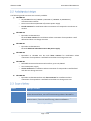
1
www.identpro.de www.identpro.de User Manual identMX © IdentPro GmbH 2010 | We reserve the right to change specifications w/o prior notice. Images and illustrations exemplary. IdentPro GmbH User Manual identMX V1.1 identMX – User Manual Page 2 of 48 IdentPro GmbH User Manual identMX V1.1 Version Version 1.1, June 2010 Copyright by IdentPro GmbH Südstraße 31 · 53757 Sankt Augustin · Germany Copying of this document and giving it to others and the use or communication of the contents thereof are forbidden without express authority. Offenders are liable to the payment of damages. All rights are reserved in the event of the grant of a patent or the registration of a utility model or design. Composition of the information in this manual has been done to the best of our knowledge. IdentPro GmbH does not guarantee the correctness and completeness of the details given in this manual and may not be held liable for damages ensuing from incorrect or incomplete information. Since despite all our efforts, errors may not be completely avoided, we are always grateful for your useful tips. When using the device always follow and obey relevant legislation regarding safety and electromagnetic radio frequency shielding. This document is subject to change without prior notice. Service To learn more about this or other products of IdentPro please visit our website: http://www.identpro.de. For technical support please email to: [email protected] Page 3 of 48 IdentPro GmbH User Manual identMX V1.1 Content 1 Safety precautions ............................................................................................................................................................ 5 2 Description ........................................................................................................................................................................... 6 3 2.1 Performance characteristics ............................................................................................................................ 6 2.2 Available product designs .................................................................................................................................... 7 2.3 Scope of delivery ...................................................................................................................................................... 7 2.4 Accessories ............................................................................................................................................................... 8 2.5 Maintenance .............................................................................................................................................................. 8 Installing and wiring .......................................................................................................................................................... 9 3.1 Interface panel .......................................................................................................................................................... 9 3.2 Power supply .......................................................................................................................................................... 10 3.2.1 PoE .................................................................................................................................................................... 10 3.2.2 12..36V Power ............................................................................................................................................ 10 3.3 3.3.1 Connecting the Interface Port .............................................................................................................. 12 3.3.2 Connecting digital IO ................................................................................................................................. 13 3.4 5 6 Installation notes................................................................................................................................................... 16 3.4.1 Flat surface mounting .............................................................................................................................. 16 3.4.2 Pole mounting .............................................................................................................................................. 17 3.4.3 Metallic surroundings .............................................................................................................................. 17 3.5 4 Cabling ....................................................................................................................................................................... 12 Onboard software ................................................................................................................................................ 18 3.5.1 Web Interface .............................................................................................................................................. 18 3.5.2 IP assignment .............................................................................................................................................. 19 Software tool .................................................................................................................................................................... 20 4.1 Installation ................................................................................................................................................................ 20 4.2 Using identMX TI................................................................................................................................................... 21 4.2.1 Establishing a connection ....................................................................................................................... 21 4.2.2 RFID configuration ................................................................................................................................. 24 4.2.3 Tag Acquisition and Inventory ............................................................................................................... 25 4.2.4 Export Inventory Data ............................................................................................................................... 27 4.2.5 RFID Firmware Update ............................................................................................................................ 27 4.2.6 Write EPC ...................................................................................................................................................... 28 Protocol reference guide ............................................................................................................................................ 29 5.1 Attribute types ....................................................................................................................................................... 31 5.2 Command codes ................................................................................................................................................... 34 5.3 Protocol sample .................................................................................................................................................... 38 Technical data .................................................................................................................................................................. 39 6.1 Specifications identMX ...................................................................................................................................... 39 Page 4 of 48 IdentPro GmbH 6.2 User Manual identMX V1.1 Antenna characteristics ................................................................................................................................... 40 7 Manufacturer´s Declaration of Conformity ....................................................................................................... 42 8 Disclaimer .......................................................................................................................................................................... 43 9 Trademark ......................................................................................................................................................................... 43 10 Constraints of use .......................................................................................................................................................... 43 Appendix A ................................................................................................................................................................................... 44 Appendix B ................................................................................................................................................................................... 45 Appendix C ................................................................................................................................................................................... 46 Appendix D ................................................................................................................................................................................... 47 1 Safety precautions The following sections explain how to install and use identMX. WARNING! Always disconnect identMX from any power supply when working on it. Do not connect while the power is on. A sudden rush of power can damage sensitive electronic components. Only experienced electronics personnel should open the chassis. CAUTION! Always ground yourself to remove any static electric charge before touching identMX. Although numerous precautions have been taken to protect the device from overvoltage and static electric discharge, damages to the device due to these influences can never be fully anticipated. It is recommended to use a grounding wrist strap at all times. Page 5 of 48 IdentPro GmbH User Manual identMX V1.1 2 Description identMX is a robust and compact EPC Class 1 Generation 2 Radio Frequency Identification (RFID) reader system which operates in the 868 MHz UHF band. Due to the smart integration of a UHF reader and antenna in the same housing the device is perfectly suited to implement low cost gates e.g. in distribution or production lines. It also allows using RFID in places where limited space calls for small hardware footprints. With its robust and weather proof design identMX can even be used in outdoor applications and on industrial trucks or other vehicles. In addition identMX can be connected to sensor systems like ultrasonic or infrared proximity switch and actuators like signal lamps, bars, or turnouts for additional functionality. The concept of reader and antenna integration significantly reduces cost of installation while increasing the secure and flawless operation at the same time. The reader is supported by IdentPro’s unique RFID Control Unit idendIQ. identIQ enables easy connectivity of RFID projects to IT and PLC systems. Page 6 of 48 IdentPro GmbH User Manual identMX V1.1 The following product versions are currently available: identMX 511 o 10/100 MBit Ethernet (10BASE-T, IEEE 802.3i / 100BASE-TX, IEEE 802.3u) communication interface o Power over Ethernet (IEEE 802.3af) remote power supply o Circular antenna for installations where orientation of transponders is unknown or random identMX 512 o Equivalent to identMX 511 but with linear antenna for installations where orientation of transponders is well defined and does not change over time identMX 521 o Equivalent to identMX 511 but with additional redundant 12V to 36V power supply identMX 522 o Equivalent to identMX 521 but with linear antenna for installations where orientation of transponders is well defined and does not change over time identMX 541 o Selectable RS-232 and RS-422 serial interface, up to 115,2kBaud o 12V to 36V power supply o circular antenna for installations where orientation of transponders is well defined and does not change over time identMX 542 o Equivalent to identMX 541 but with linear antenna for installations where orientation of transponders is well defined and does not change over time Device Package includes ID-RRS 5x1 1 x UHF reader system with integrated circular antenna (868 MHz), Online documentation, Test and commissioning software identMX TI ID-RRS 5x2 1 x UHF reader system with integrated linear antenna (868 MHz), Online documentation, Test and commissioning software identMX TI Table 1: Scope of delivery Page 7 of 48 IdentPro GmbH User Manual identMX V1.1 Following accessories are available: Device Feature ID-RRZ MK5 Universal Mounting Kit for walls, ceilings and poles *) ID-RPS 501 Standalone Power over Ethernet power supply/injector compliant with IEEE802.3af, Single port, 16 Watt ID-RRZ KS531 Assembled PoE cable for Ethernet data and power; jacks: RJ45/ Bulgin Buccaneer Series 400 PX0410/10S. Length: 3 meter ID-RRZ KS571 Assembled PoE cable for Ethernet data and power; jacks: RJ45/ Bulgin Buccaneer Series 400 PX0410/10S. Length: 7 meter ID-RRZ KSxx Assembled PoE cable for Ethernet data and power; jacks: RJ45/ Bulgin Buccaneer Series 400 PX0410/10S. Length: individual ID-RRZ SW 501 SDK Reader Interface Software as DLL for use with Microsoft Windows© XP *) Please refer to appendix A for illustrations of the Universal Mounting Kit parts. Table 2: Accessories Clean with a soft cloth only. Do not use detergents. Do not open the housing: there are no parts inside that need maintenance! In case of damage please contact IdentPro at [email protected] or call +49(0) 22 41 / 866 39 20. Page 8 of 48 IdentPro GmbH User Manual identMX V1.1 3 Installing and wiring Interface Port Interface LED Function LED Auxiliary Port Venting valve All enclosure breakouts are located on the bottom side of the device. The Interface Port provides the communication interface and power supply. The Auxiliary Port can be used to connect e.g. sensors, actuators and power supply. identMX is equipped with two multicolor LEDs located on the bottom side of the enclosure. The LEDs indicate the current status of the reader´s power supply, communication interface and RFID application. Illustration 1: Interface panel LED Color Function Description Interface (Link, Act., Power) Green Link Device has physical Ethernet connection infrastructure (host system, switch, router, etc.) Orange Activity Device exchanges data with host Red Power Device is powered Green Connected A RFID host application is connected with the device Red RFID Sense A tag has been read within an inventory Function (FLED1, FLED2 Table 3: LED display The venting valve assures the leak tightness of the device even under harsh environmental conditions (e.g. outdoor applications). Never try to loose or even dismantle this part! Page 9 of 48 to IdentPro GmbH User Manual identMX V1.1 ATTENTION! Any supply voltage outside specification can destroy the unit. The PoE models of identMX receive their power over the Ethernet cable from any Power over Ethernet (PoE) power supply compliant to IEEE 802.3af. Any components used (like PoE injectors or PoE switches) should support this standard. IdentPro offers respective accessories (see chapter 0). The PoE supply path is electrically isolated to any other port of the device (Ethernet, GPIO, etc.) as well as to the housing. This isolation is rated to withstand at least 1500V eff . This power input is protected against electrical discharge, overvoltage and reverse-polarity. This power supply enables non-PoE identMX models or PoE identMX models with the redundant Power Supply option to receive power from a broad range of ordinary DC power sources. This 12..36V power supply path provides a perfect way to run identMX in environments where PoE is up to now usually not available (e.g. vehicles, industrial process and control systems, trucks) or in applications where a maximum of operational availability is required (redundancy). This second power supply path can be used exclusively or redundant to the standard power supply over the data cable using Power over Ethernet. When being used as a redundant power supply path, the standard power supply (PoE) is dominant. This means that power from the second power supply path is only drawn when PoE drops or is not provided. Nominal Input Voltage Range 12..36V DC Power consumption Max. 8 W (operating), 3,5 W (standby) The 12..36V power supply path is electrically isolated to any other port of the device (Ethernet, PoE, etc.) as well as to the housing. This isolation is rated to withstand at least 1500V eff . This power input is protected against electrical discharge, overvoltage and reverse-polarity. The electrical interface to the 12..36V power supply path is provided by a terminal block located inside the enclosure of the identMX. To connect a device, replace the plug screw sealing the auxiliary port of the device with the provided M20 cable gland. The gland accepts cables with diameters 7 to 13 mm. Page 10 of 48 IdentPro GmbH NOTE: User Manual identMX V1.1 If you feed multiple cables through cable gland, assure proper sealing to preserve the specified ingress protection grade (IP65). Dismantle the cover (antenna) by removing the 12 screws located on the flange of the enclosure. After removing the antenna you can see a 5-pole terminal block designated “J_MX-Pwr”. Connect the positive and negative conductor of the supply line to the clamps signed “PwrA” and “PwrB” as shown on the picture below. The polarity does not have to be taken into account. To connect a lead, simply hold down the button and insert the conductor in the appropriate hole. Illustration 2: Redundant power supply input clamps NOTE: The clamps accept solid and stranded conductors with diameters from 0,5 - 1,5mm2 (resp. AWG 20 .. AWG 16). When using stranded conductors, the appliance of wire end ferrules is recommended. Page 11 of 48 IdentPro GmbH User Manual identMX V1.1 When using your own cable parts and wiring shall be according the following definition: Illustration 3: Cable wiring Manufacturer Part.-No. Description Bulgin PX0410/10S Bulgin SA3179 or SA3179/1 e.g. TM21CP-88P Buccaneer Series 400, FLEX CONNECTOR Socket, 10 circuits Buccaneer, Crimp or Solder Socket, 1A, 24- 8 28 AWG, Pack of 10 RF45 Modular Plug Connector, Compliant 1 to Category 5 Standards (or higher) Ethernet cable, Compliant to Category 5 Standards (or higher) e.g. HRS Quantity needed per unit CABLE 1 Table 4: Cable parts Recommended maximum length of the Ethernet cable is 100 meters. When communicating with the reader across a Local Area Network (LAN), connect an Ethernet cable from your hub, router or switch to the identMX interface connector. See 3.1 Interface panel for location of the connector. identMX adapts to NICs as well as to switches or hubs etc. NOTE: After connecting the reader system to power allow for up to 10 seconds for the reader to initialize. Page 12 of 48 IdentPro GmbH User Manual identMX V1.1 identMX provides an interface to connect equipment with digital inputs and outputs (GPIO). This interface can be controlled by the host application. Inputs electrical characteristics: Sinking input Reverse voltage protected Switching hysteresis Supports all types of sourcing sensors (switches, PNP-outputs, etc.) Parameter Value Maximum input voltage “High-Going” input voltage “Low-Going” input voltage max. input current 48V Min. Nom. Max. 7V 7,3V 9V 5V 6,7V 7V 10mA Table 5: Inputs electrical characteristics Outputs electrical characteristics: Sourcing output Short circuit protected Current limited Overload protected Overvoltage protected (including load dump) Supports all types of resistive, inductive and capacitive loads Parameter Value Operating voltage Nominal load current Initial peak short circuit current limit Repetitive short circuit current limit 12V to 36V 1,4A 3,0A 2,2A Table 6: Outputs electrical characteristics ATTENTION: Read chapter Safety precautions prior to making any connections to identMX. Page 13 of 48 IdentPro GmbH User Manual identMX V1.1 The electrical interface is provided by a terminal block located inside the enclosure of the identMX. To connect a device, replace the plug screw sealing the auxiliary port of the device with the provided M20 cable gland. This part accepts cables with diameters from 7 to 13 mm. Illustration 4: Auxiliary port cable gland NOTE: If you feed multiple cables through the cable gland, assure proper sealing to preserve the specified ingress protection grade (IP65). Dismantle the cover (antenna) by removing the 12 screws located on the flange of the enclosure. After removing the antenna you can see a 10-pole terminal block designated “J_MX-FieldIO”. To connect a lead, simply hold down the button and insert the conductor in the appropriate hole. NOTE: The clamps accept solid and stranded conductors with diameters from 0,5 - 1,5mm2 (resp. AWG 20 .. AWG 16). When using stranded conductors, the appliance of wire end ferrules is recommended. 1 Clamp VIO 2 GNDIO 3 VIO 4 5 6 In 1 In 2 GNDIO 7 VIO 8 Out 1 Function Comment GPIO power Connect the positive lead of the GPIO power supply to this supply positive clamp. line All clamps designated “VIO” are internally connected. GPIO power Connect the neutral lead of the GPIO power supply to this clamp. supply neutral line GPIO power In case of using 2-wire sensors (e.g. pushbutton switch or cam supply positive switch) connect the second wire of the sensor(s) to this clamp. line In case of using 3-wire sensors (e.g. inductive proximity switches) the sensor´s supply line can be connected to this clamp. All clamps designated “VIO” are internally connected. Input 1 Connect the output of a sensor to this clamp. Input 2 Connect the output of a sensor to this clamp. GPIO power To ease wiring in case of using 3-wire sensors (e.g. inductive supply neutral proximity switches) the sensors´ neutral line(s) can be connected line to this clamp. GPIO power To ease wiring in case of using 3-wire actuators (e.g. displays) the supply positive actuators´ supply line(s) can be connected to this clamp. line All clamps designated “VIO” are internally connected. Output 1 Connect the input of a actuator to this clamp. Page 14 of 48 IdentPro GmbH Clamp 9 10 Out 2 GNDIO User Manual identMX V1.1 Function Comment Output 2 GPIO power supply neutral line Connect the input of a actuator to this clamp. In case of using 2-wire actuators (e.g. signal light) connect the second wire of the actuator(s) to this clamp. In case of using 3-wire actuators (e.g. displays) the actuator´s neutral line can be connected to this clamp. Table 7: Field I/O terminal block (J_MX-FieldIO) pinning Illustration 5: Sensors and actuators sample schematic Page 15 of 48 IdentPro GmbH User Manual identMX V1.1 For mounting purposes identMX provides four M5 threaded bolts located on the reverse side of the housing. See Appendix C for location and dimensions. To mount the reader to a flat surface (concrete, wood, metal) or pole, we recommend to use the mounting kit ID-RRZ MK5, which includes all necessary mounting items (except wall plugs and according screws). Please refer to Appendix A for illustrations. Furthermore, the mounting kit allows to adjust the alignment in order to obtain the best performance from the system. Especially when placed in dusty or moist environments, we recommend mounting the device in a manner that the interface panel faces downwards. If you use a linear antenna type device (e.g. identMX 512) be aware that it´s plane of polarization should match with the tags ´orientation. Illustration 6: Orientation of the plane of polarization of the linear antenna ATTENTION! Before mounting the device, make sure that the carrying structure (wall, pole, etc.) supports the total load of reader, cabling, and, if used, mounting kit. Especially in case of portable applications make sure all cable connections are properly protected by a pull relief. ATTENTION! The reader must be installed to provide a separation distance of at least 20 cm from all persons and must not be co-located or operating in conjunction with any other antenna or transmitter. To mount the reader system on a flat surface, first assemble the antenna base bracket to the enclosure. Than attach the wall bracket to the surface. See Appendix D for drilling plan. Use the arm bracket to connect the wall bracket with the base bracket and adjust the azimuth and elevation axis. When using a reader with linear antenna make sure to match the correct orientation referred to the orientation of the transponders. (See appendix A for part illustrations.) Page 16 of 48 IdentPro GmbH User Manual identMX V1.1 To mount the reader system to a pole, first connect the base bracket to the enclosure. Than connect the pole bracket to the enclosure. Use the clamping bracket to install the reader system to the pole (recommended tightening torque 14N/m). Pay attention to suitable pole diameters (25mm – 44mm, 45mm – 76mm) and use the clamping bracket accordingly. Instead of the clamping bracket you can also use straps for bigger poles. Adjust the azimuth and elevation axis. Illustration 7: Pole mounting When installing the reader system into another device, be sure that there are no metal or metalized surfaces or objects in the direct vicinity of the antenna if possible. These can reduce the field of the integrated antenna or even detune the antenna ´s original specification. Both will result in worse overall performance of the reader i.e. reduced reading ranges and reliability. If a metallic surrounding cannot be avoided, keep the distance from the antenna surface to the metallic parts as great as possible for a stable operation. Since changes in the metallic environment may result in malfunction, no moving metal parts, such as metallic fans, should be allowed in the vicinity of the reader antenna. Page 17 of 48 IdentPro GmbH User Manual identMX V1.1 This chapter applies to models ID-RRS 521, ID-RRS 512, ID-RRS 521 and ID-RRS 522 only. The reader´s configuration can be customized to match your installation via the reader’s embedded web interface. You can access this interface from your Web browser. Simply enter the TCP/IP address of the reader in the address line of your browser. The default TCP/IP address is 192.168.1.200 and netmask 255.255.255.0. This tool allows you to adjust e.g. the TCP/IP address to your specific network. Content Navigation Frame Help Frame Menu Frame Content Frame Screenshot 1: Web-Interface Network Configuration Select a category from the Menu Frame. Where required use the Content Navigation Frame to navigate to a specific item. The Help Frame gives you information about meaning and effect of each item in the Content Frame. Via the web interface various properties can be displayed as well as configured. The Web interface offers the following features: Show general device properties (version, ID, etc.) Show general device status information Show and configure the network configuration (address allocation methods, IP address, network mask, gateway address, etc.) Show and configure communication protocol Show and configure communication security protocols Show and configure “RFID tag read event” sonic indicator (buzzer) Perform a device reset Update device firmware Page 18 of 48 IdentPro GmbH User Manual identMX V1.1 identMX offers various methods of IP assignment: Static IP address assignment Automatic address assignment using DHCP (requires a DHCP server on the local network) Automatic address assignment using BootP (requires a BootP server on the local network) IP self-assignment (also known as APIPA or Zeroconf) The following chart illustrates how the device obtains an address: Power-On or Reboot DHCP ? IP assignment successful ? enabled no yes use DHCP assigned Addess disabled BootP ? IP assignment successful ? enabled no yes disabled use BootP assigned Addess valid static IP-Address settings ? no yes is this IP-Address already in use on the network ? yes disable network interface use self-assigned Auto-IP (random 169.254.x.x) no use static IPAddress Illustration 8: IP assignment logic Before using a static IP address the device checks if this address is already used by another node on the local network. If this is the case the device disables it´s network interface to avoid an IP address conflict and consequential network malfunctions. Restart the device after abolishing the IP address conflict. Page 19 of 48 IdentPro GmbH User Manual identMX V1.1 4 Software tool identMX TI is the test and commissioning application for Microsoft Windows platforms (XP, Windows 7). The tool is primarily intended for initial testing of a identMX reader prior to deployment. It can also be used for testing the reader with your application. identMX TI can be used with any identMX type. identMX TI allows to : discover and connect to any identMX on the current network configure the network setting (IP address, network mask) modify and adjust all RFID operational parameters inventory tags review tag data and perform diagnostics write EPCs control and monitor the GPIO display the current firmware version and perform firmware updates This manual is based on identMX TI Version 1.0.5 . To install the application simply run the Setup file “setup.exe” and follow the instructions. Setup will place a shortcut on the Desktop as well as in the Windows Programs folder. Screenshot 2: identMX TI Setup Page 20 of 48 IdentPro GmbH User Manual identMX V1.1 ATTENTION: Read chapter Safety precautions prior to making any connections to identMX. Install identMX as described in chapter 3 Installing and wiring. The main dialog of the application features three frames: Menu Bar Inventory Result Frame Control and Config Frame Screenshot 3: identMX main dialog The version 1.0.5 of identMX TI requires a RFID Firmware of version 2.4.4 or higher running on the device. Prior to using the tool you should check if your device is compatible (select “Info” from the “Extras” section in the Menu bar, see “identMX RFID FW”) and if necessary perform a firmware update (see chapter 4.2.5 RFID Firmware Update). TCP identMX TI comprises a feature called Device Discovery that allows you to discover any identMX running on your local network and to connect to a device of which e.g. the IP address settings are unknown. This even works if a device currently uses an address out of the scope of the subnet of your local computer. Click on “Connection” in the Menu Bar and select “TCP/IP” Page 21 of 48 IdentPro GmbH User Manual identMX V1.1 to open the Connection Dialog. The instructions in the “Guide & Info Line” will help you using the discovery feature. In that line you will also find information about errors and the current state of the Device Discovery process. Network Interfaces List Devices List IP Assignment Frame Guide & Info Line Screenshot 4: TCP/IP connection As the dialog opens, the Network Interfaces List lists up all network interfaces available on the local computer. Double click on a entry to start scanning for devices. When the scan is completed, the MAC and current IP address of each discovered device are shown in the Devices List. NOTE: Depending on your local computer´s setup, devices may be discovered on multiple paths and therefore multiple entries representing the same device may occur in the Devices List. The property “accessible” indicates whether a device is accessible from the subnet(s) of your local computer. If it is not accessible you will have to change your local computers network settings accordingly or assign an IP address in your subnet to that device. Page 22 of 48 IdentPro GmbH User Manual identMX V1.1 NOTE: The identMX factory default TCP/IP address is 192.168.1.200 with netmask 255.255.255.0. To get an initial connection please make sure, that you can reach this address from your local computer´s subnet. You can change the address of an identMX directly from the Connection Dialog. After performing a device discovery select a device from the device list. Enter the IP address and the mask Suffix (CIDR notation) and press assign. It takes a view seconds for t he new settings to get active. Observe the information in the Guide & Info Line. Serial To establish a connection to an identMX with a serial communication interface (RS-232 or RS-422) click on “Connection” in the Menu Bar and select “Serial” to open the Serial Connection Dialog. Enter the name of the serial communication port of your local computer that is connected to the device. Once you are connected with a device, the Connection Dialog closes automatically and the device´s IP address or the local COM-Port respectively will be shown in the Connection Section of the Control and Config Frame. You can use the Disconnect / Connect button to disconnect from the device or re-establish the connection. Page 23 of 48 IdentPro GmbH User Manual identMX V1.1 With identMX TI you can change any RFID related parameter of the device. You find all these parameters in the RFID Configuration Section of the Control and Config Frame. Screenshot 5: RFID configuration section Once you are connected with a device, the current configuration running on it will be displayed. After changing any parameter you do not have to reboot or even restart the device to make the setting become active. Just press the Apply Config button. This allows you to shortly find out the ideal setting for your application. Parameter Channel LBT Mode RF-Power Modulation Q Comment The index of a radio channel according to ETSI used to communicate with RFID tags. Entries marked “DRM” are specified by ETSI to be used in Dense Reader Mode. Selects between the two methods of accessing the RF field: Listen Before Talk (checked) and Dense Reader Mode (unchecked) This is the real power of the radio field radiated by the antenna (ERP .. Effective Radiated Power) in mW. Not to mistake ERP for connected power! Selects between the data modulation (DSB .. double side band, PR .. phase reversal) and coding types (FM .. bi-phase space, M.. Miller). Each value is characterized by a specific Tag-to-Reader data bandwidth. Refer to “Specification for RFID Air Interface” Version 1.2.0, by GS1 EPCglobal, chapter 6.3.1 Signaling for further information. An integer value in the range of 0 to 15 used with tag query commands to calculate the number of slots (2Q = 1 to 32768) in an inventory round. Larger values mean more slots but slower performance, smaller values mean fewer slots but faster performance. Choose a value resulting in at least twice the number of slots than number of tags expected in an inventory at a time. E.g. if you expect to read 10 tags, choose Q=5 (25 Slots = 32 Slots). Refer to “Specification for RFID Air Interface” Version 1.2.0, by GS1 EPCglobal, chapter 6.3.2.4 Tag states and slot counter for further Page 24 of 48 IdentPro GmbH User Manual identMX V1.1 Parameter Session Dwell-Time Comment information. Choose one of four sessions (denoted S0 to S3) for tag inventory. With this parameter a reader can control the inventoried flag of tags for each session. Use session S0 if you aim to read each tag in a population within every inventory. Refer to “Specification for RFID Air Interface” Version 1.2.0, by GS1 EPCglobal, chapter 6.3.2.2 Sessions and inventoried flags for further information. Maximum antenna dwell time in ms during inventory. The device will occupy each frequency for no longer than this time. Valid values are in the range of 0 to 3000. Practical values are in the range from 500 to 2000. Table 8: RFDI Configuration Parameters The buttons have the following functions: Retrieves and displays the current configuration running on the device Fills the RFID Configuration with default values Transmits the configuration in the RFID Configuration to the device. This button only gets active if the current setting in the dialog differs from the configuration actually running in the device! The essential feature of identMX TI is the Tag Acquisition and Inventory function. This allows you to automatically read a tag population in the device´s reading range and to consecutively inventory the collected tags regarding to certain individual data. The result of the inventory will be displayed in the Inventory Result Frame simultaneously. You can start and stop the tag acquisition process any time using the Start / Stop Button. While the acquisition process is running the current rate as well as the number of tags of the last acquisition will be displayed. Prior to start the tag acquisition, configure the tag inventory criteria to ensure that each tag in the field will be clearly identified and allocated in the Inventory Result List. An acquired tag matching in terms of all inventory criterias to a previously inventoried tag will be allocated to the according entry in the inventory result list. NOTE: Multiple inventory criteria will be AND-related to determine a match to existing Inventory Result List entries. NOTE: Some tags don´t have neither a unique TID (serial number) nor individual EPCs programmed by the chip/tag manufacturer. This results in a read result of “1” even if physically several of those tags are in the field. Page 25 of 48 IdentPro GmbH Criteria TID length EPC User Manual identMX V1.1 Comment Select whether the Tag ID (TID) should be used as an inventory criterion. Specify the maximum TID length (in Bytes). If this criterion is not selected, the TID will not be taken into account to identify a tag for inventory. Select whether the EPC should be used as an inventory criterion. Make sure each tag is programmed with an individual EPC. If this criterion is not selected, the EPC will not be taken into account to identify a tag for inventory. Each tag inventoried will be listed in the Inventory Result List . For each entry, several properties will be displayed. Column # TID EPC Read count QoC Read rate RSSI Comment This is the consecutive index of the Inventory results List entry. This is the TID identifying the tag in hexadecimal representation. This is the EPC identifying the tag in hexadecimal representation. This is the count of reads for this tag since the beginning of the inventory process. Quality of capture is the ratio of the count of reads of this tag to the tag acquisition count. The rate in Hz with which this tag is read. The RSSI (Radio Signal Strength Indicator) is a characteristic for the strength of the received signal of this tag. An RSSI typically has no unit and hence is not comparable with values obtained by readers. Table 9: Inventory Result List Columns The Inventory Result List will be cleared each time the acquisition process is started. Page 26 of 48 IdentPro GmbH User Manual identMX V1.1 The result of an inventory process can be exported to a file. This allows you to e.g. archive the data collected during a trail or to use this data for post-processing. The export function of identMX TI will write an the data currently displayed in the Inventory Result List to a file in the CSV (character separated values) format. This widespread format is compatible to any spreadsheet program and can even be viewed and edited this any text editor. The inventory export function is only available while tag acquisition is in the “Stop” state. To export inventory data select “Export Inventory” from the “Extras” section in the Menu bar. A file selection dialog will appear asking you for the name and location of the export file. Firmware version 2.4.4 or higher is required on the identMX units that you want to control with the identMX TI software. To check the current firmware version of a identMX reader select “Info” from the “Extras” section in the Menu bar and see “identMX RFID FW”. Executing a firmware update depends on the communication interface that the identMX unit you want to update provides. Make sure the identMX is correctly installed as described in chapter 3 Installing and wiring. You will always find a firmware suitable to run identMX TI in the folder “Firmware” within the application folder of this tool. NOTE: Make sure to keep up power and connection to the identMX until the firmware update is fully completed! Interrupting the update process or breaking the power supply or the data stream can result in the device becoming inaccessible! TCP Devices providing a TCP/IP interface (ID-RRS 521, ID-RRS 512, ID-RRS 521 and ID-RRS 522) can be updated by FTP. Any FTP-Client application (e.g. Total Commander) can be used. Establish a connection to the device using your FTP-Client application. By default, identMX is shipped with the following FTP user credentials: User: admin Password: g93ncls0 Now you have access to the identMX´s file system. Copy the identMX RFID firmware image file (e.g. “idMX_RFID_FW_2.4.4.bin”) from your local drive to the root directory of the identMX. Rename the file to “idMX_RFID_FW.bin”. The firmware update process should start automatically. You can monitor the update progress by the pulse width of the green function LED (FLED 1) on the user panel. The update process should take about 20 seconds. When the LED constantly glows the update process has been terminated. Page 27 of 48 IdentPro GmbH User Manual identMX V1.1 Serial Devices providing a serial interface (ID-RRS 541 and ID-RRS 542) can be updated using identMX TI. Establish a connection to the device as described in chapter 4.2.1 Establishing a connection. To open the update dialog, select “Firmware update” from the “Extras” section in the Menu bar. Click the open button to select the identMX RFID firmware image file (e.g. “idMX_RFID_FW_2.4.4.bin”) from your local drive. To start the update process click Download. The update process should take about 2 minutes. The progress of the update process is shown by the progress bar. identMX TI provides a simple function to write the EPC of a tag. NOTE: In practice, reliable writing operations can be complex. The Write EPC feature as implemented in identMX TI does not exploit the capabilities of the system. This functionality has been implemented just for testing purposes and is limited to provide a simple user interface. To write an EPC, start by performing an inventory of the tags in the reader´s field. As a unique identifier for the write operation is needed, the inventory criteria “TID length” with at least 8 Byte (TID containing a Serial Number) is needed. Select the entry of the tag you wish to program in the Inventory Result List by clicking on the appropriate row. The item should be highlighted after clicking. To open the EPC Write dialog, select “Write EPC” from the “Extras” section in the Menu bar. When the Write EPC dialog appears, enter up to 12 bytes (96 bits) of data in hex format to be programmed as EPC in the EPC field. To write the data to the tag, click “Write”. Under some conditions, attempting to write data may fail (tag is not sufficiently powered, tag´s EPC is locked, the RF channel selected is occupied, etc.). Particularly if the tag is not sufficiently powered to process write operations, try to place the tag closer to the antenna. As a rule of thumb, half of the maximum reading distance is needed for writing. Page 28 of 48 IdentPro GmbH User Manual identMX V1.1 5 Protocol reference guide This Protocol Reference Guide is designed for users and developers who need to program applications to communicate with identMX readers. This chapter describes the message format of the communication protocol used by the host and the reader in order to issuing commands and reply with responses. The protocol is based on the Attribute Value Pair (AVP) schema and foresees a message header in order to identify the message scope. The command set and the firmware architecture are similar to the Reader Protocol 1.0 specification draft from EPCGlobal. Message fields are described left to right, with the most significant byte on the left and the least on the right. The identMX reader system protocol uses a synchronous command channel which is implemented on top of a TCP/IP socket and optional on a serial communication line. All messages (commands, responses and notifications) are composed by a header and a body. In all cases the body of the message is a list of attribute-value pairs. Responses always echo the Command AVP sent by the host. All the packets for the control channel share a common header format: 1 2 3 0 1 2 3 4 5 6 7 8 9 0 1 2 3 4 5 6 7 8 9 0 1 2 3 4 5 6 7 8 9 0 1 +-------------------------------+------------------------------+ | FIXED | Message ID | +-------------------------------+------------------------------+ | Vendor ID | +-------------------------------+------------------------------+ | Length | +-------------------------------+ FIXED Message ID Vendor ID Length Must be 0x8001 for commands and 0x0001 for responses. ID of the message. It is a sequence number used to map requests to its responses: a request and its corresponding response have the same message ID. Must be 0x5358. Encodes the length of the message in bytes including the header. Page 29 of 48 IdentPro GmbH User Manual identMX V1.1 The header is directly followed by a list of AVPs. The number of AVPs depends on the command. Each AVP has the following format: 1 2 3 0 1 2 3 4 5 6 7 8 9 0 1 2 3 4 5 6 7 8 9 0 1 2 3 4 5 6 7 8 9 0 1 +-------------------------------+------------------------------+ | RESERVED | Length | +-------------------------------+------------------------------+ | Attribute Type | Attribute Value ……… | +-------------------------------+------------------------------+ | ………[ until length is reached ]……… | +--------------------------------------------------------------+ RESERVED Length Attribute type Attribute value The first 16 bits are reserved for future extensions. All reserved bits must be set to 0 on outgoing messages and ignored on incoming messages. Encodes the length of the AVP packet including the length and the reserved fields. A 2 byte code identifying the attribute type. The actual attribute value according to the type. It follows immediately after the Attribute Type field and runs for the remaining bytes indicated in the Length (i.e. Length minus 6 bytes of header) Page 30 of 48 IdentPro GmbH User Manual identMX V1.1 This chapter provides a brief overview of the attribute types used by the identMX reader. In addition, the data types and length are described. Code 0x01 0x02 0x0F 0x10 Description CommandCode: the command to be executed. All command codes are specified in the relevant table. ResultCode: a code representing an indication on the result of the command. All result codes are specified in the relevant table. TagIDLen: the length of the tag ID. TimeStamp: an indication of the time. Attribute must be interpreted as follow: - the 4 least significant bytes are the seconds elapsed from the 1 Value Length [Bytes] 2 2 2 8 January 1970. 0x11 0x12 0x22 0x4D 0x4E 0x50 0x51 0x52 0x54 - the 4 most significant bytes are the micro-seconds. TagID: represents the ID of the transponder read. Attribute value has a maximum length of 12 bytes. TagType: the tag’s type. Attribute value can take on the following value: 0x03 = EPCC1G2 ReadPointName: a string representing the name of the read point. Attribute value has a maximum length of 5 bytes and can take on the following value: “Ant0” TagValue: data read from the tag memory (when applicable). Attribute value has a maximum length of 128 bytes. TagAddress: the memory location address of the tag where read or write data operation takes place. Length: a value representing the length of a parameter. BitRate: a value representing the air interface BitRate. Attribute value can take on the following values: 0x2 – Transmit : DSB ASK 40kbit, Receive : FM0 40kbit 0x5 – Transmit : DSB ASK 40kbit, Receive : Miller M=2 160kbit 0x6 – Transmit : PR ASK 40kbit, Receive : Miller M=4 250kbit 0x7 – Transmit : PR ASK 40kbit, Receive : Miller M=4 300kbit PowerGet: a value representing the current radio power. Protocol: a value representing the air protocol. Attribute value can take on the following value: 0x03 = EPCC1G2 Page 31 of 48 ≤12 2 ≤5 ≤128 2 2 2 4 4 IdentPro GmbH Code 0x57 0x60 0x61 0x62 0x63 0x64 0x67 0x69 0x6A 0x6B 0x71 0x72 User Manual identMX V1.1 Description Boolean: a value representing a boolean data. Attribute value can take on the following values: 0x00 = FALSE. Not 0x00 = TRUE. BaudRate: a value representing the baudrate setting of a serial port. DataBits: a value representing the databits setting of a serial port. StopBits: a value representing the stopbits setting of a serial port. Parity: a value representing the parity setting of a serial port. Attribute value can take on the following values: 0x00 = No parity 0x01 = Odd parity 0x02 = Even parity FlowCtrl: a value representing the flow control setting of a serial port. Attribute value can take on the following values: 0x00 = No flow control 0x01 = Hardware flow control 0x02 = Software flow control (not yet implemented) Bitmask: Inventory Flags. When set to 1, RSSI value for each tag detected is returned. Default value is 0. IORegister: a value representing the status of the I/O lines of the reader. Where input lines are separated from output ones, input lines are mapped on the less significant bits while outputs are mapped on the most significant bits. ConfigParameter: a value representing a configuration parameter. Attribute value can take on the following values: 0x00 = ReadCycle configuration 0x01 = Observed Threshold configuration 0x02 = Lost Threshold configuration 0x03 = Starting Q value (Valid values: 0 15 ). 0x04 = Session (Valid values: 0 3 ).. 0x05 = Target (Valid values: 0 1 ). 0x06 = Selected (Valid values: 0 1 ). 0x08 = Antenna dwell time during inventory (msec). 0x09 = Inventory type (Valid values: 0 3 ). ConfigValue: a value for the configuration parameter. MemoryBank: a value representing the memory bank of EPC Class 1 Generation 2 tags. Attribute value can take on the following values: 0x00 = Reserved Memory Bank 0x01 = EPC Memory Bank 0x02 = TID Memory Bank 0x03 = User Memory Bank Payload: a value representing the payload parameter for the EPC Class 1 Gen 2 lock command (see the EPC Gen2 specification for details). Page 32 of 48 Value Length [Bytes] 2 4 4 4 4 4 2 4 4 4 2 4 IdentPro GmbH Code 0x73 0x75 0x76 0x77 0x78 0x7A 0x96 0xFB User Manual identMX V1.1 Description G2Password: a value representing the Acess / Kill password parameter for the EPC Class 1 Gen 2 commands (see the EPC Gen2 specification for details). QParameter: a value representing the initial value for the Q parameter defined in the EPC Class 1 Gen 2 anticollision algorithm (see the EPC Gen2 specification for details). ReaderInfo: a ASCII byte character string indicating the model and the serial number of the reader. Attribute value has a maximum length of 30 bytes. RFRegulation: a value representing the RFID regulation to use. Attribute value can assume the following values: 0x00 = ETSI EN 302 208 0x01 = ETSI EN 300 220 RFChannel: a value representing the RF channel to use. Attribute value can take on values in the range of 0 … 9. Channels refer to the ETSI EN 302 208 regulation. RSSI: a value representing the backscattered RF field strength. PowerSet: a value representing the RF power emitted during the communication with tags. SourceName: a ASCII byte character string representing the name of the data source. Attribute value has a maximum length of 30 bytes and can take on the following value: “Source_0” Table 10: Attributes Page 33 of 48 Value Length [Bytes] 4 2 ≤30 2 2 2 4 ≤30 IdentPro GmbH User Manual identMX V1.1 This chapter provides a brief overview of the commands used by the identMX reader communication protocol (AVP 0x01, CommandCode). In addition, the data types used with each command are described. NOTE: Parameters marked with [in] must be set accordingly when sending the command. Parameters marked with [out] are returned by the system. Code Description NewRawReadIDs: permits to get all IDs of transponders within the RF field of the selected source. Parameters: SourceNameIn: [in] the name of the source to use (optional). Length: [in] Filter Mask Lenght (optional). TagID: [in] Filter Mask Value (optional). TagAddress: [in] Filter Mask Start Address (optional). Bitmask: [in] Inventory Flags. When set to 1, RSSI value for each tag detected is returned. Default value is 0. 0x13 For each tag detected the parameters returned by the command are: SourceNameOut: [out] the name of the source used. ReadPointName: [out] the name of the read-point. TimeStamp: [out] the time at which a tag is detected. TagType: [out] the type of a tag. TagIDLen: [out] the ID length of a tag detected. TagID: [out] the ID of a tag. RSSI: [out] the backscattered field strength of a tag ResultCode: [out] the result code. 0x64 0x72 0x73 0x81 SetPower: permits to set RF power level. Parameters: PowerSet: [in] the power level to set. ResultCode: [out] the result code. SetBitRate: permits to set BitRate to use. Parameters: BitRate: [in] the BitRate to set. ResultCode: [out] the result code. GetPower: permits to obtain the current RF power level. Parameters: PowerGet: [out] the current power level. ResultCode: [out] the result code. GetBitRate: permits to obtain the BitRate in use. Parameters: BitRate: [out] the BitRate in. ResultCode: [out] the result code. Page 34 of 48 IdentPro GmbH User Manual identMX V1.1 Code 0x83 0x86 0x87 0x88 0x89 0x8A 0x8B Description SetRS232: permits to modify settings of the serial port. Parameters: Baudrate: [in] the baud rate value. Databits: [in] the data bits setting. Stopbits: [in] the stop bits setting. Parity: [in] the parity setting. Flowctrl: [in] the flow control setting. ResultCode: [out] the result code. GetIO: permits to read the current status of the I/O lines. Parameters: IORegister: [out] the status of the I/O lines. ResultCode: [out] the result code. SetIO: permits to set the level of the output lines. Parameters: IORegister: [in] the value to set to the output lines. ResultCode: [out] the result code. SetIODirection: permits to define the direction of the I/O lines. (0 = input; 1 = output) Parameters: IORegister: [in] the direction to set to the I/O lines. ResultCode: [out] the result code. GetIODirection: permits to read current status of the I/O lines. (0 = input; 1 = output) Parameters: IORegister: [out] the direction of the I/O lines. ResultCode: [out] the result code. SetSourceConfig: permits to set a configuration parameter for a logical source. Parameters: SourceName: [in] the name of the source to configure. ConfigParameter: [in] the code of the parameter. ConfigValue: [in] the value for the parameter. ResultCode: [out] the result code. GetSourceConfig: permits to read a configuration parameter for a logical source. Parameters: SourceName: [in] the name of the source to configure. ConfigParameter: [in] the code of the parameter. ConfigValue: [out] the value for the parameter. ResultCode: [out] the result code. Page 35 of 48 IdentPro GmbH User Manual identMX V1.1 Code 0x96 0x97 0x98 0x99 0x9E Description G2Read: permits to read data from any of the Gen2 tag memory banks. Parameters: SourceName: [in, optional] the name of the source to use. TagIDLen: [in] the ID length of the tag. TagID: [in] the ID of the tag. MemoryBank: [in] the memory bank. TagAddress: [in] the address where to read the data. Length: [in] the number of bytes to read (must be an even number). TagValue: [out] the data read from the tag memory. G2Password: [in] the EPC Access password (optional). ResultCode: [out] the result code. G2Write: permits to write data into the Gen2 tag memory banks. Parameters: SourceName: [in] the name of the source to use. TagIDLen: [in] the ID length of the tag. TagID: [in] the ID of the tag. MemoryBank: [in] the memory bank. TagAddress: [in] the address where to write the data. Length: [in] the number of bytes to write (must be an even number). TagValue: [in] the data to write to the tag memory. G2Password: [in] the EPC Access password (optional). ResultCode: [out] the result code. G2Lock: permits to execute the tag lock command defined by the EPC Class 1 Gen 2 protocol. Parameters: SourceName: [in] the name of the source to use. TagIDLen: [in] the ID length of the tag. TagID: [in] the ID of the tag. G2Payload: [in] the lock payload. G2Password: [in] the EPC Access password (optional). ResultCode: [out] the result code. G2Kill: permits to execute the tag kill command defined by the EPC Class 1 Gen 2 protocol. Parameters: SourceName: [in] the name of the source to use. TagIDLen: [in] the ID length of the tag. TagID: [in] the ID of the tag. G2Password: [in] the kill password. ResultCode: [out] the result code. GetReaderInfo: permits to read information about the reader itself. Parameters: ReaderInfo: [out] a string with information about the reader. ResultCode: [out] the result code. Page 36 of 48 IdentPro GmbH User Manual identMX V1.1 Code 0xA1 0xA2 0xA3 0xA4 Description SetRFRegulation: permits to change the RF regulation used by the reader. Parameters: RFRegulation: [in] the desired RF regulation (see attribute type 0x77). ResultCode: [out] the result code. GetRFRegulation: permits to read the RF regulation used by the reader. Parameters: RFRegulation: [out] the desired RF regulation. ResultCode: [out] the result code. SetRFChannel: permits to set the RF channel which will be used by the reader Parameters: RFChannel: [in] the RF channel. ResultCode: [out] the result code. GetRFChannel: permits to read the RF channel currently in use. Parameters: RFChannel: [out] the RF channel. ResultCode: [out] the result code. Table 11: Command Codes Page 37 of 48 IdentPro GmbH User Manual identMX V1.1 The following sample illustrates how requests are sent to and response is received from the reader system. Shown is a NewRawReadIDs command with additionally obtaining RSSI values. Request sent: Header: AVP 1: AVP 2: AVP 3: 0x8001 0x00BF 0x00005358 0x0029 0x0000 0x0008 0x0001 0x0013 0x0000 0x000F 0x00FB 0x536F757263655F3000 0x0000 0x0008 0x0067 0x0001 (FIXED) (Message ID) (Vendor ID) (Message Length) (Reserved) (AVP Length) (AVP Type = CommandCode) (AVP Value = NewRawReadIDs) (Reserved) (AVP Length) (AVP Type = SourceName) (AVP Value = “Source_0”) (Reserved) (AVP Length) (AVP Type = Bitmask) (AVP Value = 1 ) Response received: Header: AVP 1: AVP 2:*) AVP 3:*) AVP 4:*) AVP 5:*) AVP 6:*) AVP 7:*) AVP 8:*) AVP 9: 0x1000 0x00BF 0x00005358 0x006C 0x0000 0x0008 0x0001 0x0013 0x0000 0x000F 0x00FB 0x536F757263655F3000 0x0000 0x000B 0x0022 0x416E743000 0x0000 0x000E 0x0010 0x0000000000000000 0x0000 0x0008 0x0012 0x0003 0x0000 0x0008 0x000F 0x000C 0x0000 0x0012 0x0011 0x05629FFFA0120001C0113001 0x0000 0x0008 0x007A 0x4A9E 0x0000 0x0008 0x0002 0x0000 (FIXED) (Message ID) (Vendor ID) (Message Length) (Reserved) (AVP Length) (AVP Type = CommandCode) (AVP Value = NewRawReadIDs) (Reserved) (AVP Length) (AVP Type = SourceName) (AVP Value = “Source_0”) (Reserved) (AVP Length) (AVP Type = ReadPointName) (AVP Value = “Ant0”) (Reserved) (AVP Length) (AVP Type = TimeStamp) (AVP Value) (Reserved) (AVP Length) (AVP Type = TagType) (AVP Value = EPCC1G2) (Reserved) (AVP Length) (AVP Type = TagIDLen) (AVP Value = 12Byte) (Reserved) (AVP Length) (AVP Type = TagID) (AVP Value) (Reserved) (AVP Length) (AVP Type = RSSI) (AVP Value = 19102) (Reserved) (AVP Length) (AVP Type = ResultCode) (AVP Value = Success) *) The AVPs 2-8 will be repeated for every tag received Page 38 of 48 IdentPro GmbH User Manual identMX V1.1 6 Technical data Attribute Value Frequency Air interface protocol Write/Read range Transmitting power 865 MHz … 868 MHz EPC Class1 Gen 2, ISO 18000-6C Up to 6 m, depending on transponder, application and ambient conditions 1.8 W ERP (ETSI EN 302 208), configurable in 8 steps Antenna, Gain Interface Circular, 7 dBic; Linear, 8 dBi 10/100MBit/s Ethernet TCP/IP according to IEEE 802.3 i/u External In-/Output Firmware Update 2 x Digital In, 2 x Digital Out Yes Indicators Operating temperature Storing temperature Relative humidity 2 x bi-colour LED, internal buzzer -20°C … +60°C -40°C … +85°C 5% … 95% non condensing Housing; Weight Protection rating Size (L x W x H) Power supply Aluminum / PP; less than 1.500 gram IP 65 190 x 190 x 76 mm Power over Ethernet (PoE) according to IEEE 802.3af Power consumption Max. 8 W (operating), 3,5 W (standby) Page 39 of 48 IdentPro GmbH User Manual identMX V1.1 Circular antenna (ID-RRS 511, 521, 541) Attribute Value GAIN 7.5 dBic (min) VSWR 3 dB BEAMWIDTH 1.3:1 (typical) 1.5 : 1(max) AZ: 75° (typical), EL: 73° (typical) POLARIZATION AXIAL RATIO AT BORESIGHT RHCP 2 dB (typical) 2.5 dB (max) AXIAL RATIO @ ±30º F / B RATIO 3 dB (max) -18 dB (max) Azimuth Radiation Pattern Elevation Radiation Pattern Illustration 9: Antenna radiation pattern, circular Page 40 of 48 IdentPro GmbH User Manual identMX V1.1 Linear antenna (ID-RRS 512, 522, 542) Attribute Value GAIN 8 dBi (min) VSWR 3 dB BEAMWIDTH POLARIZATION SIDE LOBES LEVEL AZIMUTH 1.3 : 1 (max) AZ: 80°(typical) EL: 71°(typical) Linear Vertical -20dB @ ±130 to±180 SIDE LOBES LEVEL ELEVATION CROSS POLARIZATION F / B RATIO -16dB @ ±130 to±180 -20dB (max) -20dB (max) ------ cross polarization Azimuth Radiation Pattern Elevation Radiation Pattern Illustration 10: Antenna radiation pattern, linear Page 41 of 48 IdentPro GmbH User Manual identMX V1.1 7 Manufacturer´s Declaration of Conformity IdentPro GmbH Südstraße 31 53757 Sankt Augustin, Germany declares in sole responsibility, that the product erklärt in alleiniger Verantwortung, dass das Produkt IP65 UHF-RFID Schreib/Lesegerät (Product description, Bezeichnung) identMX 511, identMX 512, identMX 521, identMX 522, identMX 541, identMX 542 (Type, reference number / Typ, Erzeugnisnummer) has been designed and manufactured in accordance with the following standards mit den folgenden Normen oder normative Dokumenten übereinstimmt EN 55022:2006 + A1:2007, EN 55024:1998 + A1:2001 + A2:2003 EN 302 208-2-2:2004, EN 50364:2002, EN 60950-21:2003, EN 301 489-1:2003 (Title, number of issue of standards / Titel und/oder Nummer der Normen oder normativen Dokumente) following the provisions of the directives of the European Communities gemäß den Bestimmungen der Richtlinien R&TTE Guideline 1999/5/EC ---------------------------Michael Wack Managing Director Geschäftsführer Sankt Augustin, den 20.02.2009 (Issue place and date, Ort und Datum) Page 42 of 48 IdentPro GmbH User Manual identMX V1.1 8 Disclaimer IdentPro GmbH assumes that any information given in this manual is correct at time of publication. IdentPro GmbH however resumes the right to change technical specifications or functionality of their own products, to terminate production of these products or to terminate the support for any one of these products without prior notice in writing to the customers. It is in the responsibility of the customer to assure that information available to him/her is valid. IdentPro GmbH cannot be held liable for usage of their products whatsoever. It is the customer’s responsibility that his/her systems or units that incorporate IdentPro products conform to all respective legal requirements. IdentPro GmbH does not charter any licensing of their patents neither other intellectual property nor third parties' rights. 9 Trademark IdentPro is a registered trademark of IdentPro GmbH. All other trademarks and product names are solely ownership of the respective legitimate beneficiary. 10 Constraints of use IdentPro products are not approved for use in life supporting or life preserving systems or units nor with other systems where it can be assumed that malfunction of that system will cause a substantial damage with the user. IdentPro products are furthermore not approved for use as part and parcel of any system or unit whatsoever where a malfunction of that system or unit causes a breakdown of a life supporting or life preserving system or unit or has negative impact on safety or efficiency of that life supporting or life preserving system. IdentPro customers who use IdentPro products in such applications or who sell IdentPro products intended to be used for such applications do so at their own risk and have to indemnify IdentPro from any liability whatsoever resulting from the selling IdentPro products for unqualified purpose or improper application. By using IdentPro products the user is automatically bound to these conditions and expresses his/her accordance with these conditions respectively. Page 43 of 48 IdentPro GmbH User Manual identMX V1.1 Appendix A The mounting kit ID-RRZ MK5 for identMX comprises: Pos Qty Description 1 1 Antenna base bracket 2 1 Arm bracket 3 1 Wall/Pole bracket 4 1 Clamping bracket 5 2 Bolt M8 x 70 mm 6 4 Bolt M8 x 40 mm 7 4 Bold M5 x 16 mm 8 2 Nut M8 9 4 Nut M5 10 4 Washer spring M8 11 4 Washer flat M8 12 4 Washer spring M5 13 4 Washer flat M5 Illustration Illustrations not to scale Page 44 of 48 IdentPro GmbH User Manual identMX V1.1 Appendix B The power injector: ID-RPS 501 (product supplied may look different from the one shown below) Insert cable from identMX (RJ45 jack) into socket “out” (Power Out). Insert cable from network or computer into socket “in”. Connect identMX with „out“ Assembled PoE cable: ID-RRZ KS531 ID-RRZ KS571 Connect network/com puter with „In“ RJ45 jack coming from identMX reader Page 45 of 48 IdentPro GmbH User Manual identMX V1.1 Appendix C The following illustrations show the dimensions of the identMX system (values in mm). Rear view: Illustration 11: Dimensions identMX, back view Bottom view: Illustration 12: Dimensions identMX, bottom view Page 46 of 48 IdentPro GmbH User Manual identMX V1.1 Appendix D The following illustration shows the footprint of the wall mount bracket (values in mm). Illustration 13: Dimensions identMX accessory, wall mount bracket Page 47 of 48 IdentPro GmbH User Manual identMX V1.1 Need technical support? Please email: [email protected] Want more information? See online! Browse through the latest product highlights and learn more about our solutions. www.identpro.de © 2010 IdentPro GmbH, Sankt Augustin. With this manual, all previous editions become void. Indications made in this manual may be changed without prior notice. We reserve the right to change any specification at any time without prior notice. 1006AWBMXGB Page 48 of 48