1
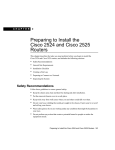
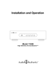
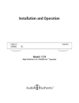
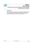
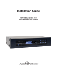
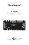
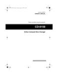
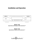
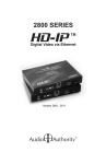
How to Install and Use the Model 1154A Signal Sensing AutoSelector
Signal Formats
• Component Video Y Pb Pr
(or *Composite Video)
• Digital Audio (both Coaxial and Optical)
• Analog Audio (Left and Right RCA)
The Model 1154A allows one of four signal sources such
as satellite, game box or DVD to be played on a home
theater system. It uses proprietary Adaptive Signal Sensing™
technology to select from among multiple sources automatically.
The high-bandwidth circuitry accepts Y P Pr component video,
stereo analog audio and digital audio in both optical and coaxial
formats. It switches all audio and video signals simultaneously
when a new source becomes active. Coaxial and optical digital
audio inputs are automatically converted to coaxial and/or optical
outputs.
Figure 1. Orient the labels (if used)
to the horizontal or vertical position
of the unit.
The Model 1154A is an enhanced version of the Model 1154, with
improved shielding, input circuitry and signal sensor adjustment
features.
Initial Installation
Use the supplied screws to secure the 1154A to any flat surface to support the heavy cables that will be connected
to it. It may be mounted horizontally or in a space-saving vertical position. Use the preprinted labels provided
or create custom labels to mark each input position.
About AutoSelection
The Model 1154A uses input signal changes to determine which one of the four inputs to select. Normally, you
will turn on the “power” to a source you want selected and leave other sources off because the 1154A looks for
newly appearing inputs as one of its decision criteria. However, two factors must also be considered. First, you
will generally keep any source that also records (a personal video recorder or PVR), powered up so it can record
even when not playing. Second, certain sources, such as cable boxes and satellite receivers, may continue to
produce output even when the “power” is off. Both of these conditions make it harder for the 1154A to correctly
anticipate which source you wish to view. Carefully following these instructions will help you to optimize the
1154A’s responses to your particular system and viewing habits.
Personal Video Recorders
When a PVR begins to record, it may fool the 1154A into selecting the PVR input, interrupting the device you
intended to watch. One way to avoid this problem is to connect the outputs of a PVR directly to a home theater
receiver or television instead of the 1154A. The PVR can then be chosen with infrared-controlled manual
selection when desired. If the PVR happens to be the only source in your system whose outputs do not turn off
when the power switch is off, you may be able to connect it to the 1154A in the lowest priority position (see
below).
Establishing Switching Priority
An example of a source that does not “turn off” is a satellite box that produces a blank digital audio bitstream
when powered down. Any digital signal is “audio” to the 1154A, therefore it may consider the source producing
the blank bitstream as active and select it for play. There are four ways to optimize the decision process and
prevent incorrect selection caused by such sources. The first of these is priority, or numerical order.
* The 1154A is designed for component video, but you may use it as an all-composite signal selector, provided you use the same video
format to the output device (video display or projector) and from all sources.
The numerical order of the sources is key to correct
operation of the Model 1154A. Generally, sources
that retain video or digital audio output even when
turned off should be connected to the highernumbered inputs. The example lists of sources in
Figure 2 are correctly prioritized from lowest to
highest input number.
These lists represent typical situations, one without
(Example A) and one with (Example B) a PVR or
automatic recording device. The sources most likely
to have constant, or null output, are placed in the
higher-numbered positions. The 1154A’s priority
system allows it to selectively ignore sources in
positions 3 and 4. Choosing the connection order
of your sources is the best way to optimize
autoselection.
Figure 2.
Priority/Source
Comment
Example A
1 DVD player
2 Game box
3 Cable box
4 Satellite receiver
Usually does not produce null output
Usually does not produce null output
Usually does not produce null output
Sat receiver may produce null output
Example B
1 DVD player
2 Cable box
3 Satellite receiver
4 PVR
Usually does not produce null output
Usually does not produce null output
May produce null output
Produces null output
Making Connections
Using the examples above, decide in what order you want to place your sources, then connect them to their
respective inputs. Start by connecting both analog and digital audio as well as video. Use either coaxial or
optical digital audio, but NOT BOTH, on a source input. You may, however, connect both the coaxial and
optical digital audio output ports of the 1154A to your home theater system, if necessary.
Connect the video output of the 1154A directly to your television or monitor, or through your home theater
receiver and then to the television. If you are using composite rather than component video, use the green Y
jacks for all video connections.
Apply power to the 1154A and turn on one source at a time to check for the desired switching behavior. You
can tell which inputs the 1154A is “seeing” by the green lamps. When a position lights green, that source is
producing output, either video or digital audio or analog audio. A solid red lamp indicates which input the
1154A has selected. A flashing red lamp indicates a selected position where no input is being received.
If at any time during the setup procedure you must change the order of the input sources or change which
signals of a source are connected, perform re-initialization as described at the end of these instructions.
Optimizing the System
Putting sources in order as described above is the first and best tool for optimizing autoselection. A second
way to improve the information coming into the 1154A’s decision process is to disconnect unneeded digital
audio inputs. In some cases, a source can be prevented from being incorrectly selected by removing its digital
audio connection and using the analog connection instead.
The third way to overcome incorrect selections is by using the Manual selection key on the 1154A front panel.
You can use this button when an occasional mis-selection occurs or when you wish to view a source for an
extended period without the chance of interruption. Note: once you have used the manual select button, the
1154A will not autoselect unless you cycle through the all the positions until the Auto lamp is lit.
Sensor Disable
Note: Before disabling any sensors, be sure you have optimized the order of your sources and connected the
best inputs from each source as described above.
Figure 3.
A final way to prevent incorrect selections is by choosing audio or video inputs
to be always ignored by the 1154A decision process. The first step is to identify
the input that is causing incorrect selections. After performing the first three
methods of optimizing, if you still observe a source being incorrectly selected,
manually select an input that is either empty or that autoselects correctly, such
as a DVD player. Now turn off all sources. If any of the positions displays a
Interpret the LEDs as follows:
• Green = Signal Present
• Red = Selected
• Flash = Selected, No Signal.
green lamp, temporarily unplug each
of the following cables from that
position, one at a time, until the green
lamp goes out:
Figure 4.
• The digital audio cable
• The Y video (green) cable
• The left analog audio cable.
If you had to unplug more than one
cable to get the green lamp to go
out, add back cable(s) until the lamp
stays off with the least number of
cables unplugged.
To set the 1154A to permanently
ignore these input(s), remove five
top cover screws (the middle screw
on the jack panel side of the cover
is not removable) and pry out the
cover. Notice a 12-position switch
on the bottom layer of circuitry in
the center of the unit.
ANALOG DIGITAL
AUDIO
AUDIO
VIDEO
1 2 3 4 1 2 3 4 1 2 3 4
1 2 3 4 5 6 7 8 9 10 11 12
ON
ON
The 1154A is shipped with all its
sensor switches turned on. With a
small tool like a screwdriver, turn
OFF the switches representing the
input(s) you unplugged. Turn off only sensor switches that you know create difficulty; do not turn off any others.
With the top cover off, plug all the cables back in and check for green lights as before. If any are observed,
repeat the cable unplugging process as before. Reinstall the cover when adjustment is complete.
Re-initialization
When you add a source or change their order, you must clear the 1154A’s memory in order to refresh the
adaptation process. This is done by performing the following steps:
• Unplug the power cord
• Hold down the Manual Select button while reapplying power
• Release the button after the panel lamps have gone out
• Unplug and replug the power cord again
Operation
The 1154A uses multiple criteria to decide when to switch sources, and will
adapt to your activity patterns by customizing its switching behavior over time.
It is able to monitor video, analog audio and digital audio to determine which
sources are active.
Figure 5.
Interpret the LEDs as follows:
• Green = Signal Present
• Red = Selected
• Flash = Selected, No Signal.
Use the Manual Select button to override automatic selection; press it briefly to advance to the next position.
A red lamp indicates which position is selected. To return to Auto mode, press the button repeatedly until the
unit has rotated through all four positions and has returned to Auto.
In Auto mode, the 1154A selects any new input that becomes active. If more than one input becomes active at
a time, or when returning from Manual to Auto mode, the 1154A selects the input with the lowest number.
Note: When playing an audio-only source, the 1154A keeps the active position selected for 15 seconds after
the audio has stopped. This prevents possible unwanted selection of another input during natural pauses in the
musical content.
Model 1154A Connection Diagram
Figure 6.
This illustration is just one example of an 1154A
wiring configuration. The following are variations
you may wish to consider:
• Connect the Analog Audio from the 1154A directly
to the TV for an alternate, simplified sound output.
• Connect component video from the 1154A to the
receiver and then to the TV, enabling the TV’s
Graphical User Interface.
• Use composite video instead of component video.
• Rearrange the source units in the order of your
desired priority.
TV
Digital Receiver/Amplifier
Video
Outputs
Audio
Outputs
719-123
AUDIO OUT
1
2 AUDIO 3
4
IN
AC Power
1
2
VIDEO
IN 3
VIDEO
OUT
4
Y
COAX
POWER
Pb
LEFT
Pr
RIGHT
12V DC
DSS Tuner
Source #4
Note: the 1154A is designed for
component video, but you may
use it as an all-composite signal
selector, provided you use the
same video format to the output
device (video display or projector)
and from all sources.
Video
Inputs
Audio
Inputs
Digital Set Top Box
Source #3
CD Changer
Source #2
DVD Player
Source #1
Source Units
2048 Mercer Road, Lexington, Kentucky 40511-1071
Phone: 859/233-4599 • Fax: 859/233-4510
Customer Toll-Free USA & Canada: 800/322-8346
Website: http://www.audioauthority.com
752-461
3/04