1
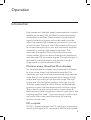
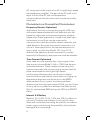
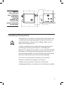
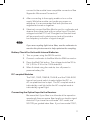
U S E R’S G U I D E
High-Speed Receivers
Models 1591, 1592, 1580-A, 1544-A, 1580-B,
1544-B, 1484-A, and 1474-A
High-Speed Detectors
Models 1480-S, 1481-S, 1414,1004, 1014,
1444, and 1024
3635 Peterson Way • Santa Clara, CA 95054 • USA
phone: (408) 980-5903 • fax: (408) 987-3178
e-mail: [email protected] • www.newfocus.com
Warranty
Newport Corporation guarantees its products to be free of defects for one
year from the date of shipment. This is in lieu of all other guarantees,
expressed or implied, and does not cover incidental or consequential loss.
Information in this document is subject to change without notice.
Copyright 2001-1998, 2013, Newport Corporation. All rights reserved.
The New Focus logo and symbol are registered trademarks of Newport
Corporation.
Document Number 90063253 Rev. A
Contents
Operation
Introduction. . . . . . . . . . . . . . . . . . . . . . . . . . . . . . . . . . . . . . . . . . . . . 5
Photoreceivers (Amplified Photodiodes). . . . . . . . . . . . . . . . . . . 5
Photodetectors (Unamplified Photodiodes) . . . . . . . . . . . . . . . . 6
Mechanical/Optical Description. . . . . . . . . . . . . . . . . . . . . . . . . . . 7
Handling Precautions. . . . . . . . . . . . . . . . . . . . . . . . . . . . . . . . . . . . 9
Powering and Connecting the Photodector/Photoreceiver. . . . . 10
Connecting the Power Supply and Bias Monitor. . . . . . . . . . 10
Battery Check For Units with Internal Batteries. . . . . . . . . . . 11
DC-coupled Modules. . . . . . . . . . . . . . . . . . . . . . . . . . . . . . . . . . . 11
Connecting the Optical Input to the Receiver . . . . . . . . . . . . . 12
Troubleshooting
Possible Problems and Solutions. . . . . . . . . . . . . . . . . . . . . . . . 13
Checking the Dark Voltage. . . . . . . . . . . . . . . . . . . . . . . . . . . . . 14
Basic Optical Test. . . . . . . . . . . . . . . . . . . . . . . . . . . . . . . . . . . . . . 15
Characteristics
Specifications Table. . . . . . . . . . . . . . . . . . . . . . . . . . . . . . . . . . . . 16
Customer Service
Technical Support. . . . . . . . . . . . . . . . . . . . . . . . . . . . . . . . . . . . . . 23
Service. . . . . . . . . . . . . . . . . . . . . . . . . . . . . . . . . . . . . . . . . . . . . . . . 23
Appendices
1: Microwave Connectors. . . . . . . . . . . . . . . . . . . . . . . . . . . . . . . 24
2: Replacing the Battery. . . . . . . . . . . . . . . . . . . . . . . . . . . . . . . . 25
3: Difference between a time-domain-optimized detector and
a frequency-domain-optimized detector. . . . . . . . . . . . . . . 25
4: DC-coupled Photoreceivers Crossover Region. . . . . . . . . 27
3
4
Operation
Introduction
High-speed and ultrahigh-speed measurements of optical
waveforms are easy with the New Focus photoreceiver/
photodetector modules. These modules convert optical
signals to electrical signals and can be used to provide
every high-speed/high-frequency instrument in your lab
an optical input. The small size of the modules allows you
to connect them directly to your test instrument, amplifier
if needed, or another high-speed component. This
eliminates the need to follow the photoreceiver with
coaxial cables, which can distort time-domain waveforms
and attenuate CW microwave signals. The optical signal is
delivered to the photodiode in the module through a
single-mode or multimode optical fiber.
Photoreceivers (Amplified Photodiodes)
For the photoreceiver models, the photodiode is followed
by a low-noise, linear, high-bandwidth amplifier. This
combines gain and low noise to reduce the input-referred
noise floor of your system and maintains linearity at high
output levels, providing a high dynamic range. The high
output level also facilitates operation with logic circuits.
The high-speed amplifier, which follows the photodiode,
produces a clean impulse response with minimal ringing.
This is ideal for digital communication measurements.
Most receivers have a negative conversion gain due to the
inverting amplifier used – if you are using an oscilloscope
and would like to see a positive output, an inverting
function can be used.
DC-coupled
For DC-coupled receivers, the DC coupling is achieved by
summing the signal’s DC component with the high-speed
5
AC component at the output of an AC-coupled high-speed
transimpedance amplifier. The gain of the DC path is set
equal to that of the AC path and temperature
compensated so that extinction ratios may be accurately
measured.
Photodetectors (Unamplified Photodiodes)
Frequency Domain Optimized
Applications that rely on transmitting signals at RF and
microwave frequencies benefit from detectors with flat
frequency responses and improved response at higher
frequencies. These applications include linear fiber-optic
transmission to and from remote antennas for
communication satellites, wireless cellular networks, and
cable television. Since the time-domain response is not
critical in these applications, the impulse response can
have ringing. In particular, Models 1414 and 1014
detectors are frequency domain optimized to provide
especially flat frequency responses over wide bandwidths.
Time Domain Optimized
If you need accurate reproduction of your signal in the
time domain, choose Model 1444 or 1024 time-domainoptimized detectors. These models provide clean, fast
impulse responses with minimal ringing, and are ideal for
pulse measurements with digital high-speed
oscilloscopes. Moreover, they can be used in digital
communications applications, where spurious ringing can
degrade eye diagrams and the bit-error-rate (BER)
measurement of your system. And, because these
detectors are internally terminated at 50 Ω, you won’t have
to worry about any reflections between the detector and
filter for standardized BER testing with SDH and SONET
filters.
Internal 9-V Battery
Models 1414, 1004, 1014, 1444, and 1024 combine an
internal 9-V battery with the bias circuitry which make
these self-contained, eliminating the need for an external
power supply and reducing the possibility of photodiode
damage due to overvoltage.
6
Mechanical/Optical Description
A gold-plated microwave housing inside the module
contains the high-frequency circuitry. This housing is bolted
to a printed-circuit board which regulates the bias for the
high frequency components and amplifies the DC
photocurrent for the monitor port. The optical signal is
brought from the front-panel connector to the microwave
housing using the appropriate fiber. In models with singlemode fiber input, the optical signal is delivered to the PIN
photodiode through a 0.1m, 9-um core optical fiber. For
multimode input the signal is delivered through a 50-μm
(or 62.5-μm) core graded-index multimode fiber of the same
length. For 12 GHz models and faster, an internal lens
focuses the light onto the small high-speed PIN photodiode.
There is no degradation in frequency response since the
fiber is ~0.1 m long. In modules with a battery, the fiber is
protected by a sheet metal flange to prevent damage while
replacing the battery.
New Focus offers several photodetectors and
photoreceivers, allowing you to match the wavelength,
bandwidth, and fiber type of your application.
power indicator LED
Figure 1:
Models 1591,
1592, 1580-B,
1544-B, and
1544-B-50
bias-monitor port
(output =1 mV/µA)
AC-DC
switch
Off
On PWR
Optical Input
Bias
Monitor
fiber-optic input
connector (FC)
7
positive supply
check
bias-monitor port
(output =1 mV/µA)
power
switch
Figure 2:
Models 1580-A,
1544-A,
1544-A-50,
1480-S, 1481-S,
and 1481-S-50
Off
On
Batt
Chk
Bias
Monitor
Optical Input
fiber-optic input
connector (FC)
battery-check button
Figure 3:
Models 1414,
1414-50, 1004,
1014, 1024,
1444, and
1444-50
bias-monitor port
(output =1 mV/µA)
power
switch
Off
On Batt
Chk
Optical Input
Bias
Monitor
fiber-optic input
connector (FC)
power indicator LED
Figure 4:
Models 1484-A,
1484-A-50, and
1474-A
bias-monitor port
(output =1 mV/µA)
Model 1474-A
35 GHz IR Photoreceiver
PWR
Optical Input
Bias
Monitor
1mV/µA
fiber-optic input
connector (FC)
8
Output K-Connector
Figure 5:
Side and back
view. (Note that
the battery
operated
modules will
not have the
power connector
on the side.)
2.26
(57.5)
2.00
(50.8)
2.00
(50.8)
1.59
(40.3)
3.15
(80.1)
.54
(13.6)
Power Connector
Handling Precautions
The detector is sensitive to electrostatic discharges and
could be permanently damaged if subjected to even to
small discharges. Whenever handling, make sure to
follow these precautions:
• Follow standard electrostatic-discharge precautions,
including grounding yourself prior to handling the
detector or making connections—even small electrostatic
discharges could permanently damage the detector. A
ground strap provides the most effective grounding and
minimizes the likelihood of electrostatic damage.
• Do not over-torque the microwave K-connector.
Excessive torque can damage connectors.
• Make sure the optical connector is clean and
undamaged before connecting it to the detector module.
9
Powering and Connecting the Photoreceiver /
Photodetector
Connecting the Power Supply and Bias Monitor
1. Prior to handling the detector, ground yourself with a
grounding strap to prevent electrostatic damage to the
module.
2. Connect the power cable to your disabled power supply.
Two power cables were included with the receiver; use the
appropriate cable for your power supply.
Connecting to a New Focus 0901 power supply:
Using the appropriate cable, connect one end of the cable
to one of the power supply’s 300-mA outputs, and the
other end to the module. If the 300-mA outputs are in use,
the 300-mA banana-plug output can also be used with the
appropriate cable. On older 0901’s, the 100-mA bananaplug output can provide enough current for certain models.
Check the current rating for your specific model in the
Power Requirements section of the specifications table.
Connecting to another power supply:
Use the cable with the three-pin power connector on one
end and three banana plugs on the other end. Be careful
to connect the banana plugs to the power supply as
follows; connect the red plug to a +15-V source; connect
the black plug to a -15-V source; connect the green plug
to the common or ground of the two sources. The +/15-V sources must be able to provide at least the required
current for your specific model. Connect the three-pin
power connector to the module.
3. Microwave Connection and Set-up
A. Connect the photoreceiver module’s K-connector to a
test instrument or component that has a 50-Ohm input
impedance. If necessary, use a high-frequency cable (best
performance is achieved without a cable).
B. To avoid connector damage and signal distortion, be
sure that the cable and the instrument you intend to
10 connect to the module have compatible connectors. See
“Appendix: Microwave Connectors”.
4. After connecting to the supply, enable or turn on the
supply. While the module can handle any power-on
sequence, it is recommended that both positive and
negative be turned on together.
5. If desired, connect the Bias Monitor port to a voltmeter and
observe the voltage level with no optical input. This dark
voltage should be < 10 mV. Changes from the dark level
will be proportional to photocurrent and will provide a
low-frequency indication of signal strength.
If you are coupling light into a fiber, use the voltmeter to
monitor the photocurrent to help optimize the coupling.
Battery Check For Units with Internal Batteries
1. Turn on power using the Off/On switch.
2. Connect a voltmeter to the Bias Monitor SMA connector.
3. Press the Batt Chk button. The voltage should be 3.5 to
5 V (-3.5 to -5 V for the 1004 detector).
4. When finished using the module, turn off power to
preserve battery life.
DC-coupled Modules
The 1591, 1592, 1580-B, 1544-B, and the 1544-B-50
have a front panel switch to select either the DC- or
AC-coupled electrical output. The DC-coupled mode is
indicated by a red light while the AC-coupled mode is
indicated by a green light.
Connecting the Optical Input to the Receiver
Be aware that if your fiber is multimode at the operation
wavelength then excessive fiber length can lead to signal
distortion. If you have the multimode “-50” model, use
50/125-μm graded index fiber. If you have model 1591,
11
1592, 1580-A, or 1580-B use 62.5/125-μm graded
index fiber. Smaller core fibers (including singlemode) will
also work well.
1. Before connecting to the photoreceiver, verify the power in
the fiber is within the safe operating range.
2. Make sure the fiber is clean and undamaged, then connect
the fiber-optic cable to the module’s input.
12 Troubleshooting
Possible Problems and Solutions
1. Low Gain:
Verify that the power supply has sufficient voltage and
current capability.
If your output signal is lower than expected, a dirty input
fiber may be causing the problem. See “Basic Optical Test”
below and verify that the input fiber is clean.
The photodiode can be damaged by electrostatic
discharge or excessive optical power, which leads to an
increased dark voltage. A damaged photodiode can result
in excess leakage current, lower responsivity, or a slower
frequency/impulse response. See “Checking the Dark
Voltage,” below. A damaged photodiode must be replaced
by New Focus.
Severe mechanical shock may misalign the optics and
lower the responsivity. See “Basic Optical Test” below. If
dirty fiber tips have been ruled out, then the module must
be repaired by New Focus.
2. Slow Response:
Verify that the power supply has sufficient voltage and
current capability.
If the frequency or time domain response is slower than
expected, then most likely the photodiode or amplifier is
damaged. See “Checking the Dark Voltage,” below. A
damaged photodiode must be replaced by New Focus. If
the dark voltage is okay, then the problem is most likely a
damaged amplifier and the module must be repaired by
New Focus.
13
Severe mechanical shock may misalign the optics. If the
frequency response drops excessively from a low
frequency up to several gigahertz (or if the time response
has a slow component) then misalignment is a possibility
and the module must be repaired by New Focus.
3. Little or No Response:
Verify that the power supply has sufficient voltage and
current capability.
After ruling out a dirty or defective fiber and making sure
there is no loss due mismatch of input fiber core diameter,
a damaged component is the most likely cause. The
module must be repaired by New Focus.
For assistance in troubleshooting or arranging for a repair,
please see the “Customer Service” section of this manual.
Checking the Dark Voltage
1. With no light entering the module, turn on power to the
detector.
2. Use a voltmeter to measure the Bias Monitor output
voltage. This voltage is the dark voltage.
3. If the dark voltage is >10 mV, then the photodiode may be
damaged and may need to be repaired by New Focus. It is
possible the module will still operate well with a voltage
only somewhat higher than 10 mV. The user may wish to
continue using the module and monitor this voltage to see
if it degrades.
14 Basic Optical Test
To quickly test your receiver, run this simple optical test.
1. Turn the receiver on.
2. Using a voltmeter or oscilloscope, measure the output
voltage from the Bias Monitor on the front panel of the
module. With no light input, the Bias Monitor voltage
should be <10 mV.
3. Illuminate the photodetector.
4. With the voltmeter or oscilloscope, you should observe a
DC output voltage. If you know the optical power and
wavelength, you can calculate the expected output voltage
(Vout) using the expression:
Vout = Pin • R • G ,
where Pin is the input optical power (Watts), R is the
photodiode’s responsivity (A/W) found on the datasheet
shipped with the unit and G is the Bias Monitor’s
transimpedance gain, 1 V/mA. If the measured voltage is
substantially less than expected, the module may need to
be returned to New Focus for repair.
15
Specifications
5-GHz Photoreceivers........................................................................................1591, 1592....................................................Table 1
12-GHz Optical Photoreceivers............................................................1580-A, 1544-A..............................................Table 2
12-GHz DC-coupled Photoreceivers...............................................1580-B, 1544-B..............................................Table 3
22-GHz Photoreceivers......................................................................................... 1484-A.........................................................Table 4
38-GHz Photoreceivers..........................................................................................1474-A.........................................................Table 4
15-GHz Photodetectors........................................................................................1480-S.........................................................Table 5
25-GHz Photodetectors................................................................................1481-S, 1414.................................................Table 5
40-GHz Photodetectors........................................................................................... 1004............................................................Table 6
45-GHz Photodetectors........................................................................................... 1014............................................................Table 6
18-ps Photodetectors................................................................................................. 1444............................................................Table 7
12-ps Photodetector.................................................................................................... 1024............................................................Table 7
Characteristics (typical, except as noted)
5-GHz Photoreceivers
Model
1591
1592
Wavelength Range
nm
450-870
950-1630
Bandwidth, 3-dB (DC
coupled), typ/min
GHz
DC to 5.5 / 4.5
DC to 5 / 4.5
Low-Frequency Cutoff
(AC coupled)
kHz
10
10
ps
80
85
600 / 500
1300 / 1100
pW/rt(Hz)
37
17
mVrms
1.8
1.8
mW
2.2
1
Maximum Safe Input,
mW
5.5
2.5
Output Impedance
Ohm
50
50
Bias-Monitor Gain
V/mA
1
1
Bias-Monitor Bandwidth
kHz
50
50
Bias-Monitor Output
Impedance
Ohm
10k
10k
+/-15 V, 150 mA
+/-15 V, 150 mA
GaAs
InGaAs
Anritsu K
Anritsu K
FC/PC
FC/PC
62.5-μm MM
62.5-μm MM
10/35
10/35
Risetime, 10-90%
Conversion Gain , typ/min V/W
2
NEP
2
Output Noise
Saturation Power
2
2,5
Power Requirements6
Detector Type
Output Connector
Input Connector
Input Fiber
Operating Temperature,
min/max
Table 1
16 °C
12-GHz Fiber Optic Photoreceivers
1580-A
1544-A
1544-A-50
Wavelength Range
Model
nm
780-870
500-1630
780-16301
Bandwidth, 3-dB,
typ / min
GHz
12 / 10.5
12 / 10.5
12 / 10.5
Low-Frequency
Cutoff
kHz
10
10
10
Risetime, 10-90%
ps
32
32
32
Conversion Gain ,
typ / max
V/W
-550 / -450
-900 / -800
-800 / -700
pW/rt(Hz)
42
24
27
mVrms
2.9
2.8
2.8
mW
1.5
0.7
0.7
Maximum Safe
Input,2,5
mW
3
2
2
Output Impedance
Ohm
50
50
50
Bias-Monitor Gain
2
NEP2
Output Noise
Saturation Power
2
V/mA
1
1
1
Bias-Monitor
Bandwidth
kHz
50
50
50
Bias-Monitor Output
Impedance
Ohm
10k
10k
10k
Power
Requirements6
+/-15 V,
200 mA
+/-15 V,
200 mA
+/-15 V,
200 mA
Detector Type
GaAs
InGaAs
InGaAs
Anritsu K
Anritsu K
Anritsu K
FC/PC
FC/PC
FC/PC
62.5-μm MM
SM
50-μm MM
10/35
10/35
10/35
Output Connector
Input Connector
Input Fiber
Operating
Temperature, min/max
°C
Table 2
17
12-GHz DC-coupled Photoreceivers
1580-B
1544-B
1544-B-50
Wavelength Range
Model
nm
780-870
500-1630
780-16301
Bandwidth, 3-dB
(DC coupled) , typ /
min
GHz
DC to
12 / 10.5
DC to
12 / 10.5
DC to
12 / 10.5
Low-Frequency
Cutoff (AC coupled)
kHz
10
10
10
Risetime, 10-90%
ps
32
32
32
Conversion Gain2,
typ/max
V/W
-550 / -450
-900 / -800
-800 / -700
NEP2
pW/rt(Hz)
42
24
27
mVrms
2.9
2.8
2.8
Saturation Power2
mW
1.5
0.7
0.7
Maximum Safe
Input,2,5
mW
3
2
2
Output Impedance
Ohm
50
50
50
Bias-Monitor Gain
V/mA
1
1
1
Bias-Monitor
Bandwidth
kHz
50
50
50
Bias-Monitor Output
Impedance
Ohm
10k
10k
10k
Power
Requirements6
+/-15 V,
200 mA
+/-15 V,
200 mA
+/-15 V,
200 mA
Detector Type
GaAs
InGaAs
InGaAs
Anritsu K
Anritsu K
Anritsu K
FC/PC
FC/PC
FC/PC
62.5-μm MM
SM
50-μm MM
10 / 35
10 / 35
10 / 35
Output Noise
Output Connector
Input Connector
Input Fiber
Operating
Temperature,min/max
Table 3
18 °C
22 and 38-GHz Photoreceivers
1484-A
1484-A-50
1474-A
Wavelength Range
Model
nm
630-865
800-8651
630-1620
Bandwidth, 3-dB,
typ / min
GHz
22/20
22/20
38/35
Low-Frequency
Cutoff
kHz
15
15
15
Risetime, 10-90%
ps
16.5
16.5
12.5
Conversion Gain ,
typ / max
V/W
-80 / -70
-75 / -65
-75 / -65
2
NEP2
pW/rt(Hz)
36
38
38
μVrms
590
590
590
Output Voltage4
V
-0.6
-0.6
-0.6
Maximum Safe
Input,2,5
mW
8
8
8
Output Impedance
Ohm
50
50
50
Bias-Monitor Gain
V/mA
1
1
1
Bias-Monitor
Bandwidth
kHz
15
15
15
Bias-Monitor Output
Impedance
Ohm
10k
10k
10k
Power Requirements
+/-12 to
+/-15V,
100 mA
+/-12 to
+/-15V,
100 mA
+/-12 to
+/-15V,
100 mA
Output Connector
Anritsu K
Anritsu K
Anritsu K
FC/PC
FC/PC
FC/PC
SM
50-µm
SM
10/35
10/35
10/35
Output Noise3
Input Connector
Input Fiber
Operating Temperature,
min/max
°C
Table 4
19
15- and 25-GHz Photodetectors
Model
1480-S
1481-S-50
1414
1414-50
400-870 400-8701
750-870
500-1630
850-16301
GHz
15 / 13
25 / 22
25 / 22
25
25
ps
25
15
15
14
14
Conversion
Gain2 typ/min
V/W
11/10
11/10
9/8
17/15
14/12
Responsivity2
A/W
0.5
0.5
0.36
0.7
0.6
Saturation
Power2
mW
2
2
2
2
2
Maximum
Safe Input,2,5
mW
5
5
5
10
10
Output
Impedance
Ohm
50
50
50
50
50
Bias-Monitor
Gain
V/
mA
1
1
1
1
1
Bias-Monitor
Bandwidth
kHz
50
50
50
50
50
Bias-Monitor
Output
Impedance
Ohm
10k
10k
10k
1k
1k
Power
Requirements6
+/-15 V,
200 mA
+/-15 V,
200 mA
+/-15 V,
200 mA
Detector Type
GaAs
GaAs
GaAs
InGaAs
InGaAs
Anritsu K
Anritsu K
Anritsu K
Wavelength
Range
nm
Bandwidth,
3-dB, typ/min
Risetime,
10-90%
Output
Connector
1481-S
Anritsu K Anritsu K
Internal 9-V
Internal
Battery
9-V Battery
Input
Connector
FC/PC
FC/PC
FC/PC
FC/PC
FC/PC
Input Fiber
62.5-μm
MM
SM
50-µm
MM
SM
50-µm MM
10 / 35
10 / 35
10 / 35
10 / 35
10 / 35
Operating
Temperature,
min/max
°C
Table 5
20 40- and 45-GHz Photodetectors
Model
1004
1014
Wavelength Range
nm
400-870
500-1630
Bandwidth, 3-dB, typ/min
GHz
40 / 35
45 / 40
ps
9
9
Conversion Gain typ/min
V/W
6.6 typ
11/9
Peak Responsivity
A/W
0.2
0.45
mW
5
2
mW
10
5
Output Impedance
Ohm
100
50
Bias-Monitor Gain
V/mA
1
1
Bias-Monitor Bandwidth
kHz
50
50
Bias-Monitor Output
Impedance
Ohm
1k
1k
Internal 9-V
Battery
Internal 9-V
Battery
GaAs
InGaAs
Anritsu K
Anritsu K
FC/PC
FC/PC
SM
SM
10/35
10/35
Risetime, 10-90%
2
Saturation Power
Maximum Safe Input
5
Power Requirements
Detector Type
Output Connector
Input Connector
Input Fiber
Operating Temperature,
min/max
°C
Table 6
21
12- and 18.5-ps Photodetectors
1444
1444-50
1024
Wavelength Range
Model
nm
500-1630
850-16301
500-1630
FWHM, Impulse
Response typ/max
ps
16.5/18.5
16.5/18.5
11/12
Bandwidth, 3-dB,
GHz
20
20
26
Conversion Gain2
typ/min
V/W
17/15
14/12
11/9
Responsivity2
A/W
0.7
0.6
0.45
Saturation Power
mW
2
2
2
Maximum Safe
Input,2,5
mW
10
10
5
Output Impedance
Ohm
50
50
50
Bias-Monitor Gain
V/
mA
1
1
1
Bias-Monitor
Bandwidth
kHz
50
50
50
Bias-Monitor Output
Impedance
Ohm
1k
1k
1k
Power
Requirements
Internal 9-V
Battery
Internal 9-V
Battery
Internal 9-V
Battery
Detector Type
InGaAs
InGaAs
InGaAs
Anritsu K
Anritsu K
Anritsu K
FC/PC
FC/PC
FC/PC
SM
50-µm MM
SM
10 / 35
10 / 35
10 / 35
2
Output Connector
Input Connector
Input Fiber
Operating Temperature,
min/max
°C
Table 7
Lens dispersion limits wavelength range.
At 1550 nm for InGaAs Models and 775nm for GaAs models. For GaAs models, response at 850nm will be similar.
3
DC - 50 GHz; noise bandwidth is ~42 GHz for each model.
4
5% compression of impulse response.
5
CW, or average power with high-speed modulation.
6
Model 0901 recommended.
1
2
22 Customer Service
Technical Support
Information and advice about the operaion of any New Focus
product is availabe from our applications engineers. For quickest
response, ask for “Technical Support” and know the model number
and serial number for your product.
Hours: 8:00–5:00 PST, Monday through Friday (excluding
holidays).
Toll Free: 1-877-835-9620
(from the USA & Canada only)
Phone:(408) 980-4330
Support is also available by fax and email:
Fax:
(408) 919-6083
Email:[email protected]
We typically respond to faxes and email within one business day.
Service
In the event that your photoreceiver malfunctions or becomes
damaged, please contact New Focus for a return authorization
number and instructions on shipping the unit back for evaluation
and repair.
23
Appendices
Appendix 1: Microwave Connectors
The performance you obtain when making high-speed
measurements depends in part on the instruments you use
and how connections are made to the instruments. Connect
the male connector of the photoreceiver directly to the
female connector of the instrument. If you need to use an
adapter, make sure it is designed for your frequency range of
interest. The following table lists common connectors, their
upper frequency limit, and mating compatibility. If you use an
intervening coaxial cable, select a shorter cable to minimize
loss and verify that its bandwidth rating is sufficient. For
more information please see the Optical Measurement
section in the Application Notes selection guide on the
Newport webpage. In particular, Application Note 1: Insights
into High-Speed Detectors and High Frequency Techniques.
Connector Type
24 Frequency Limit, GHz
Compatibility
BNC
4
-
SMA
18 or 26.5
3.5 mm, K
3.5 mm
34
SMA, K
K (2.92 mm)
40
SMA, 3.5
2.4 mm
50
V
V (1.85 mm)
65
2.4 mm
Appendix 2: Replacing the Battery
1. Turn off the module and remove the two screws on the back
panel with a Phillips screwdriver.
2. Remove the back panel and replace the battery.
3. Replace the back panel.
4. Check the battery level as described above in the “Battery
Check” section.
Appendix 3: Difference between a time-domain-optimized
detector and a frequency-domain-optimized detector
Circuitry in frequency-domain-optimized detectors is
designed to produce a flat frequency response, where the
responsivity varies only slightly across the operating
bandwidth. Time-domain-optimized detectors, in contrast,
produce clean, ring-free pulses. By using Fourier-transform
methods, you can show that clean ring-free pulses result in
a characteristic roll-off in the frequency domain. On the
other hand, a flat frequency response results in some
controlled ringing in the impulse response.
10
0
Response, dB
A
–10
B
–20
–30
–40
Frequency
Figure 7. Frequency-Domain vs. Time-Domain: (A) Detectors
designed for flat frequency response have enhanced
responsivities at high frequencies. (B) Detectors that are
optimized for clean, ring-free pulses show a characteristic
drop off in 3-dB frequency response.
25
1.2
1.0
Amplitude, a.u.
0.8
0.6
0.4
0.2
0.0
–0.2
–0.4
Time
Figure 8. Time-Domain Optimized: This is the impulse
response of a detector that is optimized for the time domain.
You can see the characteristic frequency response in the
figure above.
1.2
1.0
Amplitude, a.u.
0.8
0.6
0.4
0.2
0.0
–0.2
–0.4
Time
Figure 9. Frequency-Domain Optimized: This is the impulse
response of a detector that is optimized for a flat frequency
response. You can see the corresponding frequency
response in figure above.
26 Appendix 4: DC-coupled Photoreceivers Crossover Region
In looking at the frequency response of the DC-coupled
receivers, a “crossover” region exists where the DC response
rolls off and the AC response rises. In this region, near
25kHz, the response is not flat. Signals with significant
energy in this region will be somewhat distorted. A timedomain example is seen in Figure 10 which shows the
response for a long-duration step input. For most
applications, such as measurement of extinction ratios on
gigabit-per-second waveforms, the crossover will be
insignificant.
Figure 10. Example crossover behavior for DC-coupled
receivers.
27
28