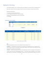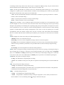
1
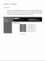
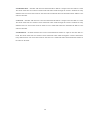
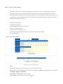
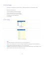
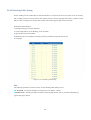
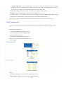
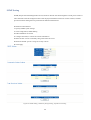
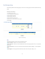
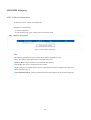
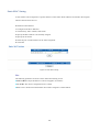
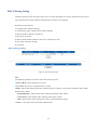
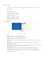
POE WEB-MANAGED
GIGABIT ETHERNET
SWITCH
with 2 SFP Ports
USER MANUAL
MODELS 560535 & 560559
INT-560535/560559-UM-0314-06
Contents
CHAPTER 1
Introduction ....................................................................................... 5
Web Browser ........................................................................................................ 5
Logging In ............................................................................................................. 6
CHAPTER 2
System................................................................................................ 8
System Information ................................................................................................... 8
IP Address Setting ................................................................................................ 8
IPv6 Address Setting ............................................................................................ 9
User Account ...................................................................................................... 10
Port Setting ......................................................................................................... 10
CHAPTER 3 Configuration...................................................................................... 12
Trunk Group Setting ........................................................................................... 12
Trunk Distribution Algorithm Setting ................................................................... 13
LACP Setting ...................................................................................................... 15
Static VLAN Table Setting .................................................................................. 16
VLAN Port Setting .............................................................................................. 17
VLAN-Stacking Table Setting ............................................................................. 18
VLAN Stacking Setting ....................................................................................... 19
IGMP Multicast Group Information ..................................................................... 21
IGMP Snooping .................................................................................................. 22
IGMP Global Setting ........................................................................................... 23
IGMP VLAN Setting ............................................................................................ 24
Spanning Tree .................................................................................................... 25
Spanning Tree Port Setting ................................................................................ 27
Quality of Service (QoS)..................................................................................... 29
Port-based Priority Setting.................................................................................. 29
DSCP-based Priority Setting .............................................................................. 30
2 Priority to Queue Mapping Setting...................................................................... 31
Packet Scheduling Setting.................................................................................. 32
LLDP Configurations .......................................................................................... 33
LLDP Neighbors ................................................................................................. 34
SNMP Setting ..................................................................................................... 35
Trap Receivers Setting ....................................................................................... 36
Port Mirroring Setting.......................................................................................... 37
Port Security Setting ........................................................................................... 38
Bandwidth Control Setting .................................................................................. 40
Jumbo Frame Setting ......................................................................................... 42
Management Access Filter ................................................................................. 43
CHAPTER 4 Security ............................................................................................... 45
MAC Address Information .................................................................................. 45
Static MAC Setting ............................................................................................. 46
MAC Filtering Setting.......................................................................................... 47
802.1x Setting..................................................................................................... 48
802.1x Port Setting ............................................................................................. 49
IP Filter Configurations ....................................................................................... 50
Storm Control settings ........................................................................................ 52
Port Isolation....................................................................................................... 53
Defence Engine .................................................................................................. 54
CHAPTER 5
Monitoring........................................................................................ 55
Port Statistics Information................................................................................... 55
CHAPTER 6 Tools.................................................................................................... 56
Http Upgrade ...................................................................................................... 56
Reset Factory Defaults ....................................................................................... 57
Reboot ................................................................................................................ 58 3 Thank you for purchasing the Intellinet Network Solutions™ PoE Web-Managed Gigabit Ethernet Switch,
Model 560535 (16-port) or 560559 (24-port). This handy switch is designed to pass both data and electrical power to a
number of PoE-compatible devices via standard Cat5e or Cat6 network cables. Easy-to-follow instructions in this user
manual help make installation quick and simple, so you’ll also soon be enjoying the benefits of these additional features:
• 10/100/1000 auto-sensing ports automatically detect optimal network speeds
• Two small form-factor pluggable GBIC module slots (SFP)
• IEEE 802.3at/af-compliant RJ45 PoE/PoE+ output ports
• Total power budget of 166 watts for 16-port; 164 watts for 24-port; power output up to 30 watts per port*
• Full/half duplex operation
• Supports IEEE 802.3at and IEEE 802.3af-compliant PoE devices
• LEDs for power, link/activity and PoE
• Supports IEEE 802.3at/af detection and short circuit, overload and high-voltage protection
• All RJ45 ports with Auto-MDIX and NWay auto-negotiation support
• Web-based configuration
• Supports bandwidth control per port
• Supports SNMP management
• Supports VLAN (tag-based and port-based)
• Provides IEEE 802.1x port-based security
• Supports link aggregation (trunking)
• Supports port mirroring
• Supports two types of QoS: port-based and DSCP
• Broadcast storm control with multicast packet rate settings
• Store and forward switching architecture
• Supports jumbo frames up to 9 kBytes
• Supports Rapid Spanning Tree/Spanning Tree protocol
• IEEE 802.3x flow control for full duplex
• Supports 16k MAC address entries
• 400 kBytes buffer memory
• Includes 19” rackmount brackets
• Three-Year Warranty
* Total PoE budget for the 16-port switch is 166 watts; 164 watts for the 24-port. Per-port average power distribution is 10
watts for 16-port; 6.8 watts for 24-port. Maximum per-port power usage cannot exceed 30 watts.
4 Logging In
Follow these steps to configure this switch.
Step 1: Use Ethernet Cat5 cable to connect this switch to your PC.
Step 2: Check that your PC has an IP address on the same subnet as the switch. For example, the PC and the
switch are on the same subnet if they both have addresses that start 192.168.1.x. The subnet mask is
255.255.255.0.
Step 3: Open the browser (such as Microsoft Internet Explorer) and go to http://192.168.1.1, which is the
switch address. If your PC is properly configured, you will see the login page below:
Figure 2: Login Popping Up Window
NOTE: If you do not see the login page, check that Steps 1 and 2 were done correctly.
Step 4: Key in both the default user name “admin” and the password “admin” to pass the authentication. After
the authentication procedure, the switch is operational and the interface menu below should display.
6 Figure 3: Web-Based Management Interface
7 CHAPTER 2
System
System Information
To look up system information in the Web browser, click System, then Information.
Web Smart switch interface
Figure 4: System Information
IP Address Setting
To set up a static IP address for the switch.
Web Smart switch interface
1. Click System, then IP Setting.
2. Set the Mode to “Static IP.”
3. Specify the IP address, subnet mask and gateway address.
4. Click Apply.
Figure 5: IP Setting
8 IPv6 Address Setting
IPv6 is an Internet Layer protocol for packet-switched internetworking and provides end-to-end datagram
transmission across multiple IP networks. IPv6 includes two distinct address types; link-local unicast and global
unicast.
Web Smart switch interface
Figure 6: IPv6 Address Setting
Hint
The following parameters are displayed on the IPv6 Address Setting page:
■ Auto Configuration—Enables stateless auto configuration of IPv6 addresses on the interface and enables IPv6
functionality on the interface.
■ IPv6 Address—Manually sets up a global unicast address by specifying the full address and network prefix
length (in the Prefix field). (Default: null)
■ Prefix Length—Defines the prefix length as a decimal value indicating how many contiguous bits (starting at
the left) of the address comprise the prefix; that is, the network portion of the address. (Default: 0)
■ Router—Sets up the IPv6 address of the default next hop router. An IPv6 default gateway must be defined if
the management station is located in a different IPv6 segment. An IPv6 default gateway can only be successfully
set when a network interface that directly connects to the gateway has been configured on the switch.
9 User Account
To set up the system password in the Web browser:
Web Smart switch interface
1. Click System, then User Account.
2. Enter the new user name.
3. Enter the new password.
4. Enter the new password again to confirm your input.
5. Click Save.
Figure 7: User Account Setting
Port Setting
To specify options for enabling auto-negotiation or manually setting the speed and duplex mode, or for enabling
flow control.
To set up port configuration in the Web browser:
1. Click System, Port Setting.
2. Select one or more ports to configure.
3. Make any required changes to the connection settings.
4. Click Apply.
10 Figure 8: Port Setting
Hint
The following parameters are displayed on the Port Setting configuration screen:
■ Port—Lets you set up one or more ports. Hold down the CTRL key and click port numbers to select multiple
ports. Hold down the SHIFT key to select a range of ports.
■ State— Lets you set the link state of port interfaces. (Default: Enabled)
■ Speed/Duplex—Configures the port speed and duplex mode using auto-negotiation or manual selection.
(Default: Auto-negotiation enabled)
■
Auto - Enables auto-negotiation. When using auto-negotiation, the optimal settings will be negotiated
between the link partners based on their advertised capabilities. Auto must be enabled for all 1 Gbps
connections.
■
100M/Full - Supports 100 Mbps full-duplex operation.
■
100M/Half - Supports 100 Mbps half-duplex operation.
■
10M/Full - Supports 10 Mbps full-duplex operation.
■
10M/Half - Supports 10 Mbps half-duplex operation.
■ Flow Control—Displays the following:
■
Config – The configured flow control mode of the port.
■
Actual – Indicates the link status of the port. When a link is up, indicates the operating flow control mode.
11 CHAPTER 3 Configuration
Trunk Group Setting
To configure a trunk group.
Web Smart switch interface
1. Click Configuration, Link Aggregation, Trunk Group Setting.
2. Select the trunk group ID to be created or modified.
3. Select the trunk type: Static or LACP.
4. Assign up to four port members to the trunk.
5. Click Add/Modify.
Figure 9: Trunk Group Setting
12 Trunk Distribution Algorithm Setting
To configure a trunk’s load-balancing settings.
Web Smart switch interface
1. Click Configuration, Link Aggregation, Trunk Setting.
2. Select the trunk group ID to be configured or modified.
3. Select the trunk Distribution Algorithm Parameters as required.
4. Click Apply.
Figure 10: Trunk Distribution Algorithm Setting
Hint
The switch provides five load-balancing methods to distribute a balanced load across all links in a trunk. The
following parameters are displayed on the Trunk Distribution Algorithm Setting screen:
■ Distribution Algorithm Parameters—To ensure the switch traffic load is distributed evenly across all links in
a trunk, the hash methods used in the load-balance calculation can be selected to provide the best result for trunk
connections. The following options are supported:
■
Source Port - All traffic with the same source and destination TCP/UDP port number is output on the same
link in a trunk. Avoid using this mode as a lone option, as it may overload a single port member of the trunk
for application traffic of a specific type, such as Web browsing. However, it can be used effectively in
combination with the IP Address option.
■
Source MAC - All traffic with the same source MAC address is output on the same link in a trunk. This
mode works best for switch-to-switch trunk links where traffic through the switch is received from many
different hosts.
13 ■
Destination MAC - All traffic with the same destination MAC address is output on the same link in a trunk.
This mode works best for switch-to-switch trunk links where traffic through the switch is destined for many
different hosts. Do not use this mode for switch-to-router trunk links where the destination MAC address is the
same for all traffic.
■
Source IP - All traffic with the same source and destination IP address is output on the same link in a trunk.
This mode works best for switch-to-router trunk links where traffic through the switch is destined for many
different hosts. Do not use this mode for switch-to-server trunk links where the destination IP address is the
same for all traffic.
■
Destination IP - All traffic with the same source and destination IP address is output on the same link in a
trunk. This mode works best for switch-to-router trunk links where traffic through the switch is destined for
many different hosts. Do not use this mode for switch-to-server trunk links where the destination IP address is
the same for all traffic.
14 LACP Setting
The LACP (Link Aggregation Control Protocol) dynamically aggregates ports and removes aggregations. LACP
interacts with its peer by sending LACPDUs (Link Aggregation Control Protocol data units).
Web Smart switch interface
To arrange LACP settings,
1. Click Configuration, Link Aggregation, LACP Setting.
2. Enable LACP on the switch.
3. Specify the LACP System Priority to identify LAGs (link aggregation groups) on the switch.
4. Click Apply.
Figure 11: LACP Setting
Hint
The following parameters are shown on the LACP Setting screen:
■ LACP Status – Specify whether LACP is enabled on this switch. LACP will aggregate two or more ports if
they belong to the same group. LACP can form up to 8 trunks per switch.
■ System Priority – LACP system priority is used to identify LAGs membership of this switch to other switches
during LAG negotiations. (Range: 0-65535, Default: 32768)
15 Static VLAN Table Setting
The VLAN (virtual local area network) technology is developed for switches to control broadcast operations in
LANs. By creating VLANs in a physical LAN, you can divide the LAN into multiple logical LANs, each of
which has a broadcast domain of its own. Hosts in the same VLAN communicate with each other as if they are in
a LAN. However, hosts in different VLANs cannot communicate with each other directly. In this way, broadcast
packets are confined within a VLAN.
Web Smart switch interface
To manage VLAN groups,
1. Click Configuration, VLAN, Static VLAN.
2. Select a VLAN ID number.
3. Define a name to identify the VLAN.
4. Mark the ports to be assigned to the new VLAN as tagged or untagged members.
5. Click Add/Modify.
Figure 12: Static VLAN Table Setting
Hint
The following parameters are shown on the Static VLAN Table Setting screen:
■ Port – Select VLAN membership for each interface by marking the appropriate radio button for a port or trunk
as Untagged, Tagged or Not Member
■ VLAN ID – VLAN Identifier. (Range: 1-4094)
■ VLAN Name – Name of the VLAN (1-100 characters)
16 VLAN Port Setting
Arranging VLAN attributes for specific interfaces, including the default Port VLAN identifier (PVID).
Web Smart switch interface
To specify attributes for VLAN port members,
1. Click Configuration, VLAN, VLAN Setting.
2. Select one or more ports or trunks to configure.
3. Configure the required PVID setting.
4. Click Apply.
Figure 13: VLAN Port Setting
Hint
The following parameters are shown on the Static VLAN Table Setting screen:
■ Port – Lets you select one or more ports to configure. Hold down the CTRL key and click port numbers to
select multiple ports. Hold down the SHIFT key to select a range of ports.
■ PVID - The VLAN ID assigned to untagged frames received on the interface. (Range: 1-4095, Default: 1) Ports
must be a member of the same VLAN as the Port VLAN ID.
17 VLAN-Stacking Table Setting
Set the stacking VLAN membership for selected interfaces to be part of the Service Provider VLAN (S-VLAN);
that is, uplink ports for a 802.1Q Tunnel. This stacking VLAN is used to segregate and preserve customer VLAN
IDs for traffic crossing the service provider network. The switch supports up to 64 S-VLAN IDs.
Web Smart switch interface
To manage stacking VLAN port members:
1. Click Configuration, VLAN Stacking, S-VLAN Table.
2. Specify the S-VLAN ID number.
3. Mark the ports to be included as stacking VLAN port members for specified S-VLAN.
4. Click Add.
Figure 14: VLAN-Stacking Table Setting
Hint
The following parameters are shown on the VLAN-Stacking Table Setting screen:
■ S-VLAN ID - The VLAN identifier of a stacking VLAN. (Range: 1-4094)
■ Member Ports - Switch ports that are members of the stacking VLAN; that is, ports that will double tag
ingress and egress packets.
18 VLAN Stacking Setting
After configuring port members for stacking VLANs on the switch, the ports connected to a service provider
network need to be enabled as double-tagged ports. Also, the Tag Protocol Identifier (TPID) value must be set for
the double-tagged ports to identify 802.1Q tagged frames.
Web Smart switch interface
To manage stacking VLAN port settings,
1. Click Configuration, VLAN Stacking, S-VLAN Setting.
2. Specify the Tag Protocol ID number.
3. Set the stacking PVID for service provider ports and configure them as “Enabled.”
4. Click Apply.
Figure 15: VLAN Stacking Setting
19 Hint
The following parameters are shown on the VLAN-Stacking Table Setting screem:
■ Tag Protocol ID – The Tag Protocol Identifier specifies the Ether type of incoming packets on a tunnel port.
(Range: 0 x 0600 – 0 x FFFF hexadecimal; Default: 0 x 88a8)
■ PVID - The stacking VLAN Port VLAN Identifier. The PVID determines the stacking VLAN tag for
single-tagged packets forwarded to an enabled S-VLAN port.
■ Provider Network Port – This lets you set the S-VLAN membership mode for the selected interface. This
mode is used to segregate and preserve customer VLAN IDs for traffic crossing the service provider network.
(Default: Disable)
■
Enable - Indicate a port linked to a service provider (an 802.1Q Tunnel port).
■
Disable - Indicate a port linked to a customer.
20 IGMP Multicast Group Information
To display multicast group and router port information, click Configuration, IGMP Snooping, Multicast Entry
Table.
The IGMP Multicast Router Information table displays the current multicast groups learned through IGMP
Snooping. Multicast routers that are attached to ports on the switch use information obtained from IGMP, along
with a multicast routing protocol such as DVMRP or PIM, to support IP multicasting across the Internet. You can
use the IGMP Multicast Router Information table to see which ports on the switch are attached to a neighboring
multicast router.
Figure 16: Multicast Entry Table
Hint
The following parameters are shown on the Multicast Entry Table screen:
■ VID - A VLAN on the switch that is forwarding multicast traffic to downstream ports for the specified
multicast group address.
■ VLAN Name – The name of the VLAN on the switch that is forwarding multicast traffic.
■ Source IP - The IP address of one of the multicast servers transmitting traffic to the specified group.
■ Group Address – IP multicast group address with subscribers directly attached or downstream from the switch,
or a static multicast group assigned to this interface.
■ Member Port – A downstream port that is receiving traffic for the specified multicast group.
■ Dynamic Router Port – The port interfaces dynamically discovered by the switch to be attached to multicast
routers.
21 IGMP Snooping
IGMP Snooping (Internet Group Management Protocol Snooping) is a multicast constraining mechanism that
runs on a Layer 2 switch to manage and control multicast groups.
Figure 17: IGMP Snooping
22 IGMP Global Setting
Web Smart switch interface
To manage IGMP Snooping global settings:
1. Click Configuration, IGMP Snooping, IGMP Snooping Setting.
2. Enable IGMP Snooping on the switch.
3. Modify other IGMP global settings as required.
4. Click Update.
Hint
The following parameters are shown on the IGMP Snooping global settings screen:
■ IGMP Snooping - When enabled, the switch will monitor network traffic to determine which hosts want to
receive multicast traffic. (Default: Disabled) This switch can passively snoop on IGMP Query and Report packets
transferred between IP multicast routers/switches and IP multicast host groups to identify the IP multicast group
members. The switch monitors the IGMP packets passing through it, picks out the group registration information,
and configures the multicast filters accordingly.
■ IGMP Fast-Leave - Immediately deletes a member port of a multicast service if a leave packet is received on
that port. Fast Leave can improve bandwidth usage for a network that frequently experiences many IGMP host
add and leave requests. (Default: Disabled)
■ Unknown Multicast - When the table used to store multicast entries for IGMP snooping is filled, no new
entries are learned. If no router port is configured in the attached VLAN, any subsequent multicast traffic not
found in the table is either dropped or flooded throughout the VLAN. (Default: Drop)
■ Query Interval - Sets the frequency at which the switch sends IGMP host-query messages. (Range: 60-600
seconds, Default: 125)
■ Response Time - Set the time between receiving an IGMP Report for an IP multicast address on a port before
the switch sends an IGMP Query out of that port and removes the entry from its list. (Range: 10-25 seconds,
Default: 10)
■ Router Timeout - On a multicast network running IGMP, a Layer 3 multicast switch may exist that serves as
an IGMP querier responsible for sending IGMP query messages. The time the switch waits after the previous
querier stops before it considers it to have expired. (Range: 60-600 seconds, Default: 125)
■ Last Member Query Interval - The interval to wait for a response to a group-specific or
group-and-source-specific query message. (Range: 1-25 seconds, Default: 1 second)
■ Robustness Variable - Specify the robustness or expected packet loss for interfaces. The robustness value is
used in calculating the appropriate range for other IGMP variables. (Range: 1-255, Default: 2)
■ Host Timeout - The time the switch waits for an IGMP report from a host for a multicast group. When IGMP
reports are not received, host ports are removed from the member list of that multicast group.
■ Querier Election Time - The time the switch waits to receive IGMP queries from other routers. If no queries
are received, the switch itself will become the querier (when enabled).
23 IGMP VLAN Setting
Web Smart switch interface
To manage IGMP Snooping settings:
1. Click Configuration, IGMP Snooping, IGMP Snooping Setting.
2. Specify the VLAN ID.
3. Enable IGMP Snooping on the VLAN.
4. Enable IGMP Querier on the VLAN if you want this switch to be elected as querier.
5. Click Apply.
Hint
The following parameters are shown on the IGMP Snooping VLAN settings screen:
■ VLAN ID - Specifies the ID of a configured VLAN on the switch. (Range: 1-4094)
■ VLAN Name - Displays the name of the VLAN.
■ Snooping State - Enable IGMP snooping on the VLAN. (Default: Disabled)
■ Querier State - Enable IGMP querier on the VLAN. (Default: Disabled)
24 Spanning Tree
The Spanning Tree Protocol is used to eliminate loops in a local area network. A switch running this protocol
detects any loop in the network by exchanging information with one another and eliminates the possible loop by
blocking certain ports until the loop network is pruned into a loop-free tree, thereby avoiding infinite recycling of
packets in a loop network. Web Smart switch interface
To manage global settings for Spanning Tree:
1. Click Configuration, Spanning Tree, STP Global Setting.
2. Set the Spanning Tree Status to enabled.
3. Modify other required parameters.
4. Click Apply. Figure 18: spanning tree settings
Hint
The following parameters are shown on the Spanning Tree settings screen:
■ Spanning Tree Status - Enable Spanning Tree on the switch. (Default: Disabled)
■ Force Version - Select the type of spanning tree used on this switch. Options: RSTP or STP, Default: RSTP
■ Priority - Bridge priority is used in selecting the root switch, root port and designated port. The switch with the
highest priority becomes the STP root switch. However, if all switches have the same priority, the switch with the
lowest MAC address will then become the root switch. Note that lower numeric values indicate higher priority.
(Options: 0-61440, in steps of 4096; Default: 32768)
■ Maximum Age - The maximum time (in seconds) a switch can wait without receiving a configuration
message before attempting to reconfigure. All switch ports (except for designated ports) should receive
25 configuration messages at regular intervals. Any port that ages out STP information (provided in the last
configuration message) becomes the designated port for the attached LAN. If it is a root port, a new root port
is selected from among the switch ports attached to the network. (Note that references to “ports” in this section
mean “interfaces,” which includes both ports and trunks.)
Minimum: The higher of 6 or [2 x (Hello Time + 1)]
Maximum: The lower of 40 or [2 x (Forward Delay - 1)]
Default: 20
■ Hello Time - The interval (in seconds) at which the root switch transmits a configuration message.
Default: 2
Minimum: 1
Maximum: The lower of 10 or [(Max. Message Age / 2) -1]
■ Forward Delay - The maximum time (in seconds) this switch will wait before changing states (i.e.,
discarding to learning to forwarding). This delay is required because every switch must receive information
about topology changes before it starts to forward frames. In addition, each port needs time to listen for
conflicting information that would make it return to a discarding state; otherwise, temporary data loops might
result.
Minimum: The higher of 4 or [(Max. Message Age / 2) + 1]
Maximum: 30
Default: 15
■ Root Priority - The priority of the switch in the Spanning Tree that this switch has accepted as the root
switch.
■ Root MAC Address - The MAC address of the switch in the Spanning Tree that this switch has accepted as
the root switch.
■ Root Path Cost - The path cost from the root port on this switch to the root switch.
■ Root Port - The number of the port on this switch that is closest to the root. This switch communicates with
the root switch through this port. If there is no root port, then this switch has been accepted as the root switch
of the Spanning Tree network.
■ Root Maximum Age - The maximum time (in seconds) this switch can wait without receiving a
configuration message before attempting to reconfigure. All switch ports (except for designated ports) should
receive configuration messages at regular intervals. If the root port ages out STA information (provided in the
last configuration message), a new root port is selected from among the switch ports attached to the network.
(References to “ports” in this section mean “interfaces,” which includes both ports and trunks.)
■ Root Hello Time - The interval (in seconds) at which this switch transmits a configuration message.
■ Root Forward Delay - The maximum time (in seconds) this switch will wait before changing states (i.e.,
discarding to learning to forwarding). This delay is required because every switch must receive information
about topology changes before it starts to forward frames. In addition, each port needs time to listen for
conflicting information that would make it return to a discarding state; otherwise, temporary data loops might
result.
■ Topology Changes - The number of times the Spanning Tree has been reconfigured.
■ Last Topology Change Time - The time since the Spanning Tree was last reconfigured.
26 Spanning Tree Port Setting
Use the STP Port Setting screen to configure Spanning Tree attributes for specific interfaces, including path cost,
port priority, edge port (for fast forwarding), automatic detection of an edge port, and point-to-point link type.
Web Smart switch interface
To configure port settings for Spanning Tree:
1. Click Configuration, Spanning Tree, STP Port Setting.
2. Modify the required attributes for one or a group of ports.
3. Click Apply.
Figure 19: spanning tree port settings
Hint
The following parameters are shown on the Spanning Tree Port settings screen:
■ Path Cost — This parameter is used by the STP to determine the best path between devices. Therefore, lower
values should be assigned to ports attached to faster media, and higher values assigned to ports with slower media.
(Path cost takes precedence over port priority.)
■ Priority — Specify the priority used for this port in the Spanning Tree Protocol. If the path cost for all ports on
a switch is the same, the port with the highest priority (i.e., lowest value) will be configured as an active link in
the Spanning Tree. This makes a port with higher priority less likely to be blocked if the Spanning Tree Protocol
27 is detecting network loops. Where more than one port is assigned the highest priority, the port with the lowest
numeric identifier will be enabled. (Range: 0-240, in steps of 16; Default: 128)
■ P2P - The link type attached to an interface can be set to automatically detect the link type, or to be manually
configured as a point-to-point or shared medium. Transition to the forwarding state is faster for point-to-point
links than for shared media. These options are described below.
■
Auto - The switch automatically determines if the interface is attached to a point-to-point link or to a shared
medium. (This is the default setting.)
■
True - A point-to-point connection to exactly one other bridge.
■
False - A shared connection to two or more bridges.
■ Edge (Fast Forwarding) - You can enable this option if an interface is attached to a LAN segment that is at the
end of a bridged LAN or to an end node. Since end nodes cannot cause forwarding loops, they can pass directly
through to the spanning tree forwarding state. Specifying edge ports provides quicker convergence for devices
such as workstations or servers; retains the current forwarding database to reduce the amount of frame flooding
required to rebuild address tables during reconfiguration events; does not cause the spanning tree to initiate
reconfiguration when the interface changes state; and also overcomes other STP-related timeout problems.
However, remember that this feature should only be enabled for ports connected to an end node device. (Default:
False)
■ State - Displays the current state of this port within the Spanning Tree.
■
Disabled - There is no connection to the port.
■
Discarding - Port receives STP configuration messages, but does not forward packets.
■
Learning - Port has transmitted configuration messages for an interval set by the Forward Delay parameter
without receiving contradictory information. The port address table is cleared, and the port begins learning
addresses.
■
Forwarding - Port forwards packets and continues learning addresses.
■ Role - Roles are assigned according to whether the port is part of the active topology connecting the bridge to
the root bridge (that is, root port), connecting a LAN through the bridge to the root bridge (that is, designated
port), or is an alternate or backup port that may provide connectivity if other bridges, bridge ports or LANs fail
or are removed. The role is set to disabled (that is, disabled port) if a port has no role within the spanning tree.
■ Path Cost - The path cost setting for the port.
■
Config - The administrator configured path cost setting.
■
Actual - The contribution of this port to the path cost of paths toward the spanning tree root that includes this
port.
■P2P - The point-to-point setting for the port.
■
Config - The administrator-configured P2P setting.
■
Actual - The operational point-to-point status of the LAN segment attached to this interface. This parameter
is determined by manual configuration or by auto-detection.
■Edge — The Edge setting for the port.
■
Config — The administrator-configured Edge setting.
■
Actual — This parameter is initialized to the port setting for Edge (that is, True or False), but will be set to
false if a BPDU is received, indicating that another bridge is attached to this port.
28 Quality of Service (QoS)
QoS is the evaluation on the service ability of network delivery or on the capacity of dealing with situations such
as delay, delay jitter and packet loss rate in packet delivery. Port-based Priority Setting
Management of the default port priority for each port on the switch.
Web Smart switch interface
To configure global settings for Spanning Tree:
1. Click Configuration, QoS, Port-based Priority.
2. For one or a group of ports, set the default priority value.
3. Click Apply.
Figure 20: Port-based Priority Setting
Hint
The following parameters are shown on the Port-based Priority Setting screen:
■ Priority - The default priority used when adding a tag to untagged frames. (Range: 0-7; Default: 0)
29 DSCP-based Priority Setting
The Differentiated Services Code Point (DSCP) is a six-bit field in the IP header, allowing coding for up to 64
different forwarding behaviors. The DSCP replaces the ToS bits, but it retains backward compatibility with the
three precedence bits so that non-DSCP-compliant, ToS-enabled devices will not conflict with the DSCP
mapping. Based on network policies, different kinds of traffic can be marked for different kinds of forwarding.
Note that all the DSCP values that are not specified are mapped to priority value 0.
Web Smart switch interface
To configure port-level DSCP remarking:
1. Click Configuration, QoS, DSCP-based Priority.
2. Map one or more DSCP values to a priority value.
3. Click Apply.
Figure 21: DSCP-based Priority Setting
Hint
The following parameters are shown on the DSCP-based Priority Setting screen:
■ DSCP - List the DSCP values. (Range: 0-63)
■ Priority - Map a priority value to the selected DSCP Priority value.
Note that 0 represents low priority and 7 represent high priority.
■ DSCP Priority Table - Show the DSCP to Priority map.
30 Priority to Queue Mapping Setting
The QoS technique known as class of service (CoS) is a three-bit field within an Ethernet frame header when
using tagged frames on an 802.1 network. So up to eight separate traffic priorities are defined in IEEE 802.1p.
You can map the priority levels to the switch’s output queues in any way that benefits application traffic for a
network.
Web Smart switch interface
To configure port-level DSCP remarking:
1. Click Configuration, QoS, Priority to Queue Mapping.
2. Map one or more priority values to a queue ID.
3. Click Apply.
Figure 22: Priority to Queue Mapping Setting
Hint
The following parameters are shown on the DSCP-based Priority Setting screen:
■ Priority - CoS value. (Range: 0-7, where 7 is the highest priority)
■ Queue ID - Output queue buffer. (Range: 1-8, where 8 is the highest priority queue)
31 Packet Scheduling Setting
You can set the switch to service the queues based on a strict rule that requires all traffic in a higher-priority
queue to be processed before lower-priority queues are serviced. Weighted Fair Queuing (WFQ) or Weighted
Round-Robin (WRR) queuing specifies a relative weight of each queue. The traffic classes are mapped to one of
the eight egress queues provided for each port. You can assign a weight to each of these queues (and thereby to
the corresponding traffic priorities). This weight sets the frequency at which each queue will be polled for service,
and subsequently affects the response time for software applications assigned a specific priority value.
Web Smart switch interface
To configure port-level DSCP remarking:
1. Click Configuration, QoS, Packet Scheduling.
2. Select the scheduling algorithm, WFQ or WRR.
3. Map scheduling weights to a queue ID, or select “Strict.”
4. Click Apply.
Figure 23: Packet Scheduling Setting
Hint
The following parameters are shown on the DSCP-based Priority Setting screen:
■ Scheduling Algorithm - Select the service method used for port egress queues.
■
Weight-fair-queue - Service the egress queues containing data based on the weight of the queue compared
to the sum of the weights of all queues. (This is the default selection.)
32 ■
Weight-round-robin - Share bandwidth at the egress ports by using the scheduling weights for queues 1
through 8, respectively. WRR specifies a relative weight for each queue that determines the percentage of
service time the switch services each queue before moving on to the next queue.
■ Queue ID - Output queue buffer. (Range: 1-8, where 8 is the highest-priority queue)
■ Weight - Set a new weight for the selected traffic class. (Range: Strict or 1-15)
Use queue weights 1-15 for queues to allocate service time based on WFQ or WRR. Queue weights must be
configured in ascendant manner, assigning more weight to each higher-numbered queue.
Strict priority requires all traffic in the queue to be processed before lower-priority queues are serviced.
LLDP Configurations
LLDP is a Layer 2 protocol that uses periodic broadcasts to advertise information about the sending device.
Web Smart switch interface
To configure global and port settings for LLDP:
1. Click Configuration, LLDP, LLDP Settings.
2. Enable LLDP for the switch.
3. If required, modify other LLDP parameters.
4. For one or a group of ports, set the LLDP mode.
5. Click Apply.
Figure 24: LLDP Settings
Hint
The following parameters are shown on the LLDP Settings screen.
■ LLDP Status - Enable LLDP on the switch. (Default: Disabled)
33 ■ Transmission Interval - Configure the periodic transmit interval for LLDP advertisements. (Range: 5-32768
seconds; Default: 30 seconds)
This attribute must comply with the following rule: (Transmission Interval * Transmission Hold Time) ≤ 65536,
and Transmission Interval ≥ (4 * Transmission Delay)
■ Hold Time Multiplier - Configure the time-to-live (TTL) value sent in LLDP advertisements as shown in the
formula below. (Range: 2-10; Default: 3)
The time-to-live tells the receiving LLDP agent how long to retain all information pertaining to the sending
LLDP agent if it does not transmit updates in a timely manner. TTL in seconds is based on the following rule:
(Transmission Interval * Transmission Hold Time) ≤ 65536. Therefore, the default TTL is 30*3 = 90 seconds.
■ Port - Port identifier. (Range: 1-18)
■ State - Enable LLDP message transmit and receive modes for LLDP Protocol Data Units. (Options: Disabled,
Tx/Rx, Rx only, Tx only; Default: Disabled)
LLDP Neighbors
To display information about devices connected directly to the switch’s ports that are advertising information
through LLDP.
Web Smart switch interface
To display LLDP neighbors, click Configuration, LLDP, LLDP Neighbors.
Click Refresh to update the LLDP information.
Figure 25: LLDP Neighbors
Hint
The following parameters are shown on the LLDP Neighbors screen:
■ Local Port - The local port to which a remote LLDP-capable device is attached.
■ Chassis ID - An octet string indicating the specific identifier for the particular chassis in this system.
■ TTL - Indicate the time (in seconds) the remote device’s information should be treated as valid.
■ LLDP Entry Number - The number of the LLDP table entry.
34 SNMP Setting
SNMP (Simple Network Management Protocol) monitors network switches through the TCP/IP protocol suite. It
offers automatic network management and avoids the physical differences between various switches, and thus
provides automatic management of products from different manufacturers. Web Smart switch interface
To specify SNMP system settings:
1. Click Configuration, SNMP Setting.
2. Enable SNMP for the switch.
3. Configure the Name, Location and Contact information.
4. Define at least one new community string with read-write access.
5. Delete the default “private” string for security reasons.
6. Click Apply.
Figure 26: SNMP Setting, Community Strings Setting, Trap Receivers Setting
35 Hint
The following parameters are shown on the SNMP Setting, Community Strings Setting.
■ SNMP Status - Enable or disable SNMP service. (Default: Disabled)
■ System Name - A name assigned to the switch system.
■ System Location - Specify the system location.
■ System Contact - An administrator responsible for the system.
■ String - A community string that acts like a password and permits access to the SNMP protocol.
Default strings: “public” (read-only access), “private” (read-write access) Range: 1-32 characters, case sensitive
■ Type - Specifies the access rights for the community string:
■ Read-Only
■
- Authorized management stations are only able to retrieve MIB objects.
Read-Write - Authorized management stations are able to both retrieve and modify MIB objects.
Trap Receivers Setting
Traps indicating status changes are issued by the switch to specified trap managers. You must specify trap
managers so that key events are reported by this switch to your management station (using network management
software).
Web Smart switch interface
To configure SNMP system settings:
1. Click Configuration, SNMP Setting.
2. Specify the IP address of management station that will receive SNMP trap messages.
3. Specify a configured community string for the trap receiver.
4. Click Apply.
Hint
The following parameters are shown on the Trap Receivers Setting screen:
■ IP Address - IP address of a new management station to receive notification messages.
■ Community String - Specify a valid community string for the new trap manager entry. The string must already
be defined in the Community String Setting section. (Range: 1-32 characters, case sensitive)
36 Port Mirroring Setting
Port mirroring includes local mirroring groups, remote source mirroring groups and remote destination mirroring
groups. Web Smart switch interface
To configure port mirroring:
1. Click Configuration, Port Mirroring.
2. Select the Mirror Set Index.
3. Select the Mirror Direction.
4. Select the Mirroring (target) port.
5. Select the one or more mirrored (source) ports.
6. Click Apply.
Figure 27: Port mirroring
Hint
The following parameters are shown on the Port Mirroring screen:
■ Mirror Set Index - Display a list of current mirror sessions.
■ Mirror Direction - Allows you to select which traffic to mirror to the target port, Rx (receive) or Tx (transmit).
(Default: Rx)
■ Mirrored Port List - One or more source ports whose traffic will be monitored. (Range: 1-18 and configured
trunks)
■ Mirroring Port - The target port that will mirror the traffic on the source ports. (Range: 1-18)
37 Port Security Setting
Port security is a feature that allows you to configure a switch port with a maximum number of MAC addresses
that are authorized to access the network through that port. When port security is enabled on a port, the switch
stops learning new MAC addresses on the specified port when it has reached a configured maximum number.
Only incoming traffic with source addresses already stored in the dynamic or static address table will be accepted
as authorized to access the network through that port. If a device with an unauthorized MAC address attempts to
use the switch port, the intrusion will be detected and the switch can automatically take a specified action.
Web Smart switch interface
To configure port security:
1. Click Configuration, Port Security.
2. Select the ports to configure.
3. Set Security to Enable.
4. Configure the maximum number of MAC addresses allowed on the port.
5. Set an action for port security violations.
6. Click Apply.
Figure 28: Port security
Hint
The following parameters are shown on the Port Security screen:
■ Port - Port number.
■ Security - Enable or disable port security for the selected ports. (Default: Disabled)
38 ■ Maximum L2 Entry - The maximum number of MAC addresses that can be learned on a port. (Range: 0 16447, where 0 means disabled)
■ Action - Indicate the action to be taken when a port security violation is detected:
■
Trap to CPU: Send an SNMP trap message. (This is the default.)
■
Drop: Drop other traffic from the port.
■
Forward: No action is taken. Traffic is forwarded as usual.
39 Bandwidth Control Setting
This function allows the network manager to control the maximum rate for traffic received on a port or
transmitted from a port. Rate limiting is configured on ports at the edge of a network to limit traffic into or out of
the switch. Packets that exceed the acceptable amount of traffic are dropped.
Rate limiting can be applied to individual ports or trunks. When an interface is configured with this feature, the
traffic rate will be monitored by the hardware to verify conformity. Non-conforming traffic is dropped;
conforming traffic is forwarded without any changes. Input and output rate limits can be enabled or disabled for
individual interfaces.
Web Smart switch interface
To configure bandwidth control:
1. Click Configuration, Bandwidth Control.
2. Select the ports to configure.
3. Set Type to Ingress or Egress.
4. Set State to Enable.
5. Configure the maximum rate allowed on the ports.
6. Click Apply.
Figure 29: bandwidth control
Hint
The following parameters are shown on the Bandwidth Control screen:
■Port - Display the port/trunk number.
40 ■Type - Specify ingress or egress traffic. (Default: Ingress)
■State - Enable or disable the rate limit. (Default: Disabled)
■Rate (kbit/sec) - Set the rate limit level. (Range: 0 - 1048544 kbps in steps of 16)
41 Jumbo Frame Setting
The switch provides more efficient throughput for large sequential data transfers by supporting jumbo frames up
to 9216 bytes.
Web Smart switch interface
To configure Jumbo Frames:
1. Click Configuration, Jumbo Frames.
2. Select the frame size to configure.
3. Click Apply.
Figure 30: Jumbo Frame Setting
Hint
The following parameters are shown on the Jumbo Frame screen:
■ Jumbo Frame (Bytes) - Configure support for jumbo frames. (Options: 9216, 1522, 1536, 1552 Bytes; Default:
9216 bytes)
42 Management Access Filter
To create up to eight IP addresses or IP address groups that are allowed access to the switch through the Web
browser.
Web Smart switch interface
1. Click Configuration, Management Access Filter.
2. Enter an IP address.
3. Specify a netmask to define a single IP address, or an address range.
4. Select the table entry to activate the filter.
5. Click Apply.
Figure 31: Management Access Filter
Hint
The following parameters are shown on the Management Access Filter screen:
■ IP Address - An IP address specifies a range that is allowed management access to the switch.
■ IP Netmask - A mask that specifies a single IP address or a range of IP addresses. (Default: 255.255.255.255
for a single IP address)
43 Power over Ethernet Setting
Power over Ethernet (PoE) means that power-sourcing equipment (PSE) supplies power to powered devices (PD)
such as IP telephones, wireless LAN access points and Web camera from Ethernet interfaces through twisted pair
cables.
Web Smart switch interface
1. Click Configuration, Power over Ethernet.
2. Select the port number of the connected PD.
3. Specify the PD on.
4. Click Apply.
Figure 32: Power over Ethernet
Hint
The following parameters are shown on the Power over Ethernet screen:
■ PD - Enable the powered devices. The consumption power in Watts will be shown in the table below. ■ Class - Indicates the PD classification.
■ Consumption Power (W) - Indicates the PD power consumption.
Once the PSE has detected the PD’s power class, the PSE can manage the power allocation by subtracting the
PD’s class maximum value from the overall power budget. This allows for control and management of power
allocation when there is not enough power available from the PSE to supply maximum power to all ports.
44 CHAPTER 4 Security
MAC Address Information
To display the MAC address forwarding table.
Web Smart switch interface
1. Click Configuration.
2. Then click Security, MAC Address, MAC Forwarding Table.
Figure 33: MAC Address Information
Hint
The following parameters are shown on the MAC Address Information screen:
■ No. - The number of the address entry in the forwarding table.
■ MAC Address - Physical address associated with this interface.
■ VLAN ID - The ID of a configured VLAN (1-4094).
■ Type - Indicates if the MAC address has been dynamically learned or configured as a static entry.
■ Port - Indicates the port.
■ Clear Dynamic Entries - Removes all dynamically learned addresses from the forwarding table.
45 Static MAC Setting
A static address can be assigned to a specific interface on the switch. Static addresses are bound to the assigned
interface and will not be moved.
Web Smart switch interface
To configure static MAC addresses:
1. Click Security, MAC Address, Static MAC.
2. Specify the MAC address to be statically assigned.
3. Specify the VLAN ID.
4. Select the port or trunk interface for the static assignment.
5. Click Add.
Figure 34: Static MAC Setting
Hint
The following parameters are shown on the Static MAC Setting screen:
■ MAC Address - Physical address of a device mapped to an interface.
■ VLAN ID - The ID of a configured VLAN (1-4094).
■ Port - Port or trunk associated with the device that is assigned as a static address.
46 MAC Filtering Setting
The MAC Filtering screens are used to filter service to clients attempting to access the Internet based on protocol
type, destination/source MAC address and the direction of traffic for each packet.
Web Smart switch interface
To configure MAC Address Filtering:
1. Click Security, MAC Address, MAC Address Filtering.
2. Specify the MAC address to be filtered.
3. Specify the VLAN ID.
4. Select to filter the MAC address as the source, destination or both.
5. Set a name to describe the filter.
6. Click Add.
Figure 35: MAC Filtering Setting
Hint
The following parameters are shown on the MAC Filtering screen:
■ MAC Address - Physical address of a device.
■ VLAN ID - The ID of a configured VLAN (1-4094).
■ Filter - Filter traffic matching the MAC address in packets. (Options: Source MAC, Destination MAC, Both;
Default: Source MAC)
■
Destination MAC - Filter packets with a matching destination MAC address.
■
Source MAC - Filter packets with a matching source MAC address.
■
Both - Filter packets with a matching the source or destination MAC address.
■ Name - A descriptive name for the MAC address filter.
47 802.1x Setting
The 802.1x Protocol provides port authentication and must be enabled globally for the switch system before port
settings are active.
Web Smart switch interface
To configure 802.1x global settings:
1. Click Security, 802.1x, 802.1x Setting.
2. Set 802.1x to Enabled.
3. Specify the RADIUS server IP address.
4. Specify the RADIUS server shared key.
5. Modified other parameters as required.
6. Click Apply.
Figure 36:
802.1x Setting
Hint§
The following parameters are shown on the 802.1x screen:
■802.1x - Sets the global setting for 802.1x. (Default: Disabled)
■RADIUS Server IP - Address of the authentication server.
■Server Port - Network (UDP) port of RADIUS server used for authentication messages. (Range: 1024-65535;
Default: 1812)
■Shared Key - Encryption key used for RADIUS server messages. Do not use blank spaces in the string.
(Maximum length: 30 characters)
■Retype Shared Key - Re-type the string entered in the previous field to ensure no errors were made. The switch
will not change the encryption key if these two fields do not match.
■ReauthEnabled - Set clients to be re-authenticated after the interval specified by the Reauth Period.
Re-authentication can be used to detect if a new device is plugged into a switch port. (Default: Enabled)
■Reauth Period - Set the time period after which a connected client must be re-authenticated. (Range: 30-65535
seconds; Default: 3600 seconds)
48 802.1x Port Setting
When 802.1x is enabled, you need to configure the parameters for the authentication process that runs between
the client and the switch (that is, authenticator), as well as the client identity lookup process that runs between the
switch and authentication server.
Web Smart switch interface
1. Click Security, 802.1x, 802.1x Port Setting.
2. Select one or more ports to configure.
3. Set the 802.1x Mode to “Authentication.”
4. Click Apply.
Figure 37: 802.1x Port Setting
Hint
The following parameters are shown on the 802.1x Port Setting screen:
■ Mode - Sets the authentication mode to one of the following options:
■
Force-Authorized - Force the port to grant access to all clients, either dot1x-aware or otherwise.
■
Force-Unauthorized - Force the port to deny access to all clients, either dot1x-aware or otherwise.
■
Authentication - Require a dot1x-aware client to be authorized by the authentication server. Clients that are
not dot1x-aware will be denied access.
■
No Authentication - Disable 802.1x authentication on the port. (This is the default setting.)
■ State - Show the current status of the 802.1x authentication process.
49 IP Filter Configurations
IP Filter Security is a feature that filters IP traffic on port interfaces based on manually configured entries in the
IP Filter table or allowed IP address assignment through DHCP. IP Filter Security can be used to prevent traffic
attacks caused when a host tries to use the IP address of a neighbor to access the network.
Web Smart switch interface
To configure IP Filter settings:
1. Click Security, IP Filter Setting.
2. Select one or more ports to configure.
3. Select the mode Static and set an IP address, or select DHCP.
4. Select ports on which to allow traffic to DHCP servers.
5. Click Apply.
Figure 38: IP Filter Configurations
Hint
The following parameters are shown on the IP Filter Configurations screen:
■ Mode - Configure the switch to filter traffic based on IP addresses. (Default: IP Filter Disable)
■
IP Filter Disable - Disable IP filtering on the port.
■
Static - Enable traffic filtering based on IP addresses configured in the table.
■
DHCP - Enable traffic filtering based on IP addresses assigned through DHCP.
50 ■ IP Address - An IP address, or an address specifying a range, that is allowed access through the switch.
■ IP Netmask - A mask that specifies a single IP address or defines a range of IP addresses. (Default:
255.255.255.0)
■ DHCP Server Allowed - Permit traffic from a DHCP server through the specified ports. (Default: All ports
allowed)
51 Storm Control settings
Broadcast storms may occur when a device on your network is malfunctioning, or if application programs are not
well designed or properly configured. If there is too much broadcast traffic on your network, performance can be
severely degraded or everything can come to complete halt. You can protect your network from broadcast storms
by setting a threshold for broadcast traffic. Any broadcast packets exceeding the specified threshold will then be
dropped.
Web Smart switch interface
To configure Storm Control settings:
1. Click Security, Storm Control.
2. Select the Storm Control type.
3. Select one or more ports to configure.
4. Set the State to “On” and set the threshold rate.
5. Click Apply.
Figure 39: Storm Control settings
Hint
The following parameters are shown on the Storm Control screen:
■ Storm Type - Select the storm control type. (Broadcast, Multicast, Unknown Unicast, Unknown Multicast)
■ Port - Select port and trunk interfaces. (Port Range: 1-18)
■ State - Enable or disable storm control. (Default: Off)
■ Rate - Threshold as packets per second (pps). (Range: 0-1000000)
52 Port Isolation
The feature provides port-based security and isolation of local ports. The switch isolates port traffic by specifying
those ports to which it can forward or receive traffic.
Web Smart switch interface
To configure Port Isolation settings:
1. Click Security, Port Isolation.
2. Select one or more ports to configure.
3. Select one or more ports to which traffic can be forwarded and received.
4. Click Apply.
Figure 40: Port Isolation
Hint
The following parameters are shown on the Port Isolation screen:
■ Port - Select port and trunk interfaces. (Port Range: 1-18)
■ Port Isolation List - Select port and trunk interfaces to which traffic can be forwarded and received. (Port
Range: 1-18; Default: All ports and trunks)
53 Defence Engine
Defence (sic) Engine is an advanced feature that can prevent the switch’s CPU from being overwhelmed by
flooded packets, such as unknown unicast, unknown multicast or broadcast packets. This function can be used to
prevent malicious viruses or worm attacks.
Web Smart switch interface
To configure Defence Engine settings:
1. Click Security, Defence Engine.
2. Set Defence Engine status to Enabled.
3. Click Apply.
Figure 41: Defence Engine
Hint
The following parameters are shown on the Defence Engine screen:
■ Defence Engine - Enable or disable the feature. (Default: Enabled)
54 CHAPTER 5
Monitoring
Port Statistics Information
You can display standard statistics on network traffic passing through each port. This information can be used to
identify potential problems with the switch, such as a faulty port or unusually heavy loading. All values displayed
have been accumulated since the last system reboot.
Web Smart switch interface
Click Monitoring, Port Statistics to display port statistics.
Figure 42: Port Statistics Information
Hint§
The following parameters are shown on the Port Statistics Information screen:
■ Port - The port number.
■ State - Display the link state of port interfaces (Enabled or Disabled).
■ Link Status - Display the link state of the port interface (Link Up or Link Down).
■ TxGoodPkt - The total number of packets transmitted out of the interface.
■ TxBadPkt - The total number of outbound packets that could not be transmitted because of errors.
■ RxGoodPkt - The total number of packets received on the interface.
■ RxBadPkt - The total number of inbound packets that contained errors preventing them from being
deliverable.
■ Clear - Click the button to reset all counters.
55 CHAPTER 6 Tools
Http Upgrade
Use the HTTP Upgrade screen to upgrade the switch’s system firmware by specifying a new software file. You
can also use the HTTP Upgrade screen to save the current configuration to a file on your computer or to restore
previously saved configuration settings to the switch.
Web Smart switch interface
To upgrade switch software:
1. Click Tools, HTTP Upgrade.
2. Click Browse and select the firmware file.
3. Click Upgrade to upgrade the switch’s firmware.
After the software file is uploaded, the switch prompts for a reboot.
Figure 43: Http Upgrade
Hint
The following parameters are shown on the Http Upgrade screen:
■ HTTP Configuration Backup - Click the Backup button to save the current configuration settings to a file on
the local Web management station.
■ HTTP Configuration Restore - Restore previously saved configuration settings to the switch from a file on
the local Web management station. Use the Browse button to locate the configuration file, then click Restore.
■ HTTP Firmware Upgrade - Upgrade the switch software from a file on the local Web management station.
Use the Browse button to locate the software file, then click Upgrade.
56 Reset Factory Defaults
To restore factory defaults.
Web Smart switch interface
Click Tools, Reset, then click the Reset button. The reset will be complete when the Web browser displays the
login page.
Figure 44: Reset
57 Reboot
To restart the switch.
Web Smart switch interface
To click Tools, Reboot, then click the Reboot button. The reboot will be complete when the Web
interface displays the login page.
Figure 45: Reboot
58