1
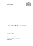
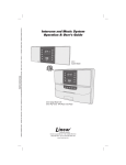
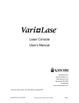
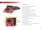
Systems & Accessories
•
•
•
•
•
•
Light Source
Sample Chambers
Stepping Motor Controller
Detector
Variable Wavelength Fiber Optics Modules
Tunable Light Sources
For Applications In:
Analytical Chemistry
Physics
Life Sciences
Engineering
Communications
Optometrics Corporation
Wavelength Selection Solutions
Optometrics Corporation
Products
• Gratings
Originals and Replicated, Ruled and Holographic;
Grazing Incidence, Echelles, Telecom and
Transmission Gratings
O
ptometrics Corporation has, for more than forty
years, designed and manufactured optical components and instruments for university, industrial and
government laboratories and the OEM markets.
Optometrics Corp. has manufactured over 20,000 MiniChrom monochromators since their initial introduction
in 1978. The majority have been incorporated into a
variety of analytical and biomedical instruments made
and marketed by leaders in their respective fields.
For those customers wishing to configure their own
optical systems built around or to equip their laboratory
with modules that work with the popular Mini-Chrom
monochromator, Optometrics has designed compatible
systems. These include a light source, sample chambers, stepping motor controller and detector. Customers can also choose selected modules to configure
their own variable wavelength fiber optic modules or
choose the turnkey Tunable Light Sources, all built
around our line of Mini-Chrom monochromators.
Facilities
• Beamsplitters
Reflecting/Transmitting
Beamsplitters,
Transmission Grating
Beamsplitters, Beam
Dividers/Combiners
• Optical Components
Mirrors, Lenses, Windows, Flats, Beamsplitters,
Prisms
• Filters
Soft Coated, Near Ultraviolet, Visible, Near Infrared, and Laser Line Filters
• Infrared & Laser
Products
Laser Gratings,
Holographic and Ruled
Wire Grid Polarizers
• Monochromators
Mini-Chrom
Monochromators
Optometrics’ facility in Ayer, Massachusetts contains space
for offices, engineering, R&D and production. Equipment
that support our broad range of capabilities includes:
• Four metal vacuum coating systems;
• Three thin-film soft coated filter vacuum
coating systems;
• Two Ion-Assisted Deposition hard coat vacuum
coating systems;
• Three grating ruling engines;
• Production holographic laboratory;
• R&D holographic laboratory;
• Full replication and lamination facilities;
• Full assembly, alignment and test facilities;
• Full complement of test equipment for spectral testing from the UV to the Far Infrared, for mechanical and flatness testing, for humidity and environmental testing;
• Extensive marking, packaging and bar coding
equipment and capabilities
Page 2
email: [email protected]
• Systems & Accessories
Monochromatic Light Modules, Sample
Compartments, Detectors, Light Sources, Modular
Recording Spectrophotometers
• SPF-290S Analyzer
Spectrophotometer for determining SPF Values
Plus specialized packaging, bar coding and Kanban
stocking arrangements for OEM customers.
www.optometrics.com
Optometrics Corporation
Systems & Accessories
Goals
Optometrics goal is to provide advanced optical components and systems for use in wavelength selection
applications in:
• Analytical Chemistry
• Life Sciences
• Telecom Applications
• Physics
• Education
• Space Sciences
and other applications where high quality optics are key.
TABLE OF CONTENTS
Systems & Accessories
Tungsten Source Module ...................................4
Sample Compartments
Sample Compartment..................................5
Specular Reflectance
Sample Compartment..................................6
Long Pass Cut-On Filters ...................................7
Stepping Motor Controller ..................................8
In order to accomplish this, the Company has assembled
state-of-the-art facilities and people to produce:
• diffraction gratings: ruled & holographic, original &
replicated, reflection and transmission
• interference filters
• optical components
• laser gratings & products
• monochromators & accessories
• spectrophotometers
• wire grid polarizers: ruled & holographic
Detector Module..................................................9
Tunable Light Sources.......................................10
Variable Wavelength Fiber Optic Module .........12
Ordering Information
Terms & Conditions...........................................13
Order Form ......................................................14
OEM Services
Optometrics caters, in particular, to the needs of its
OEM customers by offering special services such as:
• Kanban stocking arrangements
• Custom packaging programs
• Bar coding capabilities
• Code names for complete confidentiality
• Higher level pre-aligned optical assemblies
Optometrics Corporation
8 Nemco Way
Ayer, MA 01432 USA
Tel: (978) 772-1700
Fax: (978) 772-0017
E-Mail: [email protected]
The company is also proud of its ability to support customers in all phases of the product development cycle.
Optometrics Corporation
email: [email protected]
www.optometrics.com
Page 3
Systems & Accessories Tungsten Source Module
TUNGSTEN SOURCE MODULE
The Tungsten Source Module includes a 20W tungsten
halogen lamp in a quartz envelope, a lamp housing, shutter assembly and variable aperture assembly on a base
plate and a regulated 12V DC power supply. Halogen
compounds in the lamp recycle tungsten deposited on the
inside of the envelope back to the filament. This cycling
of tungsten prevents the gradual degradation of the lamp
output, particularly in the ultraviolet and increases the life
of the lamp. The module can be used as a visible and
near infrared source (340 nm to 3 µ) or as a building block
to construct a variety of spectrophotometric systems.
The module has provisions for attaching a Mini-Chrom
monochromator and/or an adapter plate*. The addition
of a Mini-Chrom converts the Tungsten Source Module
to a compact and versatile monochromatic light source. A
quartz lens in the lamp housing focuses radiation from the
tungsten lamp onto the entrance slit of the Mini-Chrom,
obviating the need for additional optics and time consuming alignment. With an adapter plate, the module can be
easily attached to the Optometrics Sample Compartment
(see page 5). A Silicon Detector (see page 9) can then
be added, resulting in a manual spectrophotometer or
fluorometer. Overall dimensions in mm: 203 x 114 x 62;
Weight 0.9 Kg (2.0 lbs).
* See Optometrics’ Monochromators brochure for details on models available.
SPECIFICATIONS
Lamp Power Supply:
Line regulation.........................................................0.1%
Load regulation...........................................................1%
Ripple....................................................1 mV RMS Max.
Input Voltages................................. 105-126V AC, 60 Hz
210-252V AC, 50 Hz
Output.......................................................... 12V DC/ 2 A
(3 A start-up surge)
Internal overcurrent protection provided.
CATALOG
NO.
Lamp:
Type...................... Tungsten Halogen in quartz envelope
Power...................................................................... 20 W
Color temperature..............................................3200 K
Nominal life.......................................................500 hours
Spectral output.............................................340 nm - 3 µ
Connector....................................................... G-4 plug-in
˚
TUNGSTEN SOURCE MODULE
PRICE ($)
7-1110
Tungsten Source Module with Regulated power supply for 105-125V AC.
1150.00
7-1125
Tungsten Source Module with Regulated power supply for 210-225V AC.
1150.00
7-1130
Adapter plate for attaching Tungsten Source Module to Sample Compartment.
7-1120
20W Tungsten Halogen lamp replacements (package of two).
Page 4
email: [email protected]
www.optometrics.com
150.00
35.00
Optometrics Corporation
Sample Compartment Systems & Accessories
SAMPLE COMPARTMENT
The versatile Optometrics Sample Compartment accepts
standard 1 cm square cells or solid samples up to 50 x
50 x 10 mm. A quartz lens focuses incident radiation in
the center of the cell or on the front surface of a solid
sample depending on the position of the sample stage.
Two additional quartz lenses focus transmitted, reflected
or emitted radiation at the in-line or 90 degree detector
ports. A filter holder, which accepts Optometrics’ 25.4 mm
diameter filters, is attached to the inside of each port.
When measuring the percent transmittance or absorbance
of a solution or a transparent solid sample, the sample
stage and detector are positioned in-line. Fluorescence or
nephelometric measurements are made with the detector
positioned 90 degrees to the incident radiation. Reflectance measurements from solid samples require rotating
the sample stage 45 degrees and placing the detector
90 degrees to the incident radiation (see Optical Path
Configuration drawing below). Overall dimensions in mm:
218 x 168 x 92; Weight 2.5 Kg (5.4 lbs.)
For information on a detector that plugs into the sample
compartment, see page 9. If monochromatic radiation
is required, our Tungsten Source Module (see page 4)
and either a Digital or Scanning Digital Monochromator
can be attached to the Sample Compartment with the
Adapter Plate.
* See Optometrics’ Monochromators brochure for details on models available.
OPTICAL PATH CONFIGURATIONS
ATALOG
C
NO.
7-1200
SAMPLE COMPARTMENT
PRICE ($)
Sample Compartment with three 1” focal length quartz lenses, three filter holders, two detector ports, rotary sample stage and sample holders.
Optometrics Corporation
email: [email protected]
www.optometrics.com
1,900.00
Page 5
Systems & Accessories Specular Reflectance Sample Compartment
SPECULAR REFLECTANCE
SAMPLE COMPARTMENT
The Specular Reflectance Sample Compartment is
designed to measure the reflectance of solid samples
such as mirrors, paint samples, etc. It attaches to the exit
port of an Optometrics Mini-Chrom monochromator* with
the use of the Adapter Plate (see page 4). Monochromatic
light from the exit slit of the monochromator is reflected
onto the sample, which is held in position by a springloaded mount. The angle of incidence at the sample is 11
degrees. Light from the sample is reflected to a detector at
the exit port. The unit is supplied with a mirror for making
a reference measurement.
The standard Sample Compartment, (see page 5)
measures samples at a 45 degree angle of incidence,
whereas the Specular Reflectance Sample Compartment
is designed for measurements requiring a smaller angle
of incidence. Maximum sample size is 7 x 14 cm.
* See Optometrics’ Monochromators brochure for details on models available.
OVERALL DIMENSIONS IN MILLIMETERS
SPECULAR REFLECTANCE
SAMPLE COMPARTMENT
Page 6
email: [email protected]
CATALOG
NO.
SAMPLE COMPARTMENT
PRICE ($)
8-0050
Specular Reflectance Sample Compartment
2,650.00
www.optometrics.com
Optometrics Corporation
Long-Pass Cut-On Filters Systems & Accessories
LONG PASS CUT-ON FILTERS
CUT-ON FILTER
Long pass cut-on filters have an average high transmission of 85% from 15 to 20 nm above their cut-on wavelength to 2000 nm. Attenuation of radiation below the
cut-on wavelength is due to absorption of the colorants in
the glass and the thickness of the glass. Superior blocking in Optometrics’ filters (0.001%) is due to the use of 3
mm thick color glass.
Optometrics‘ long pass cut-on filters are all epoxied in a
black metal ring for easy mounting and handling and are
100
TRANSMITANCE (%)
Long pass cut-on filters are used to prevent higher order
radiation from the grating monochromator from entering
the sample compartment. Optometrics‘ long pass cut-on
filters are cored from selected color glasses which transmit radiation above and block radiation below a specified
wavelength. The wavelength interval (transition interval)
from blocking to maximum transmission is sharp, typically 25 to 35 nm. Long pass cut-on filters are identified
by a cut-on wavelength, i.e. the wavelength at 50% of
maximum transmission.
50%
Cut-on wavelength
0
WAVELENGTH (nm)
25.4 mm dia. x 9.65 mm thick. The cut-on wavelength is
marked on all filters. Designed to mount directly in the
Optometrics’ sample chamber (see page 5).
GENERAL SPECIFICATIONS
Cut-on Wavelength ...............................................± 5 nm
Blocking (Short wavelengths) ............................0.001%
Transmission...................................................... ≥ 85%
Transmission Range..........................Cut-on to 2000 nm
Dimensions and Tolerances:
Diameter (Mounted)...................25.4 mm ± 0.25 mm
Thickness (Mounted)..................9.65 mm ± 0.15 mm
Clear Aperture............................20.0 mm ± 0.25 mm
LONG PASS CUT-ON FILTERS
CATALOG
NO.
MINI-CHROM MODEL NO.
CUT-ON λ
PRICE ($)
7-1201
01
375 nm
60.00
7-1202
02 & 03
420 nm
60.00
7-1204
04
630 nm
60.00
7-1205
05 & 06
1200 nm
60.00
Optometrics’ long pass cut-on filters are all epoxied in a black metal ring for easy
handling and mounting in our sample chamber and are 25.4 mm dia. x 9.65 mm thick.
The cut-on wavelength is marked on all filters
Optometrics Corporation
email: [email protected]
www.optometrics.com
Page 7
Systems & Accessories Stepping Motor
STEPPING MOTOR CONTROLLER
The PCM-02 is ideally suited for driving the Optometrics
line of Scanning Digital Monochromators*.
Using a computer, the operator can move the monochromator to a specific wavelength and scan over a wavelength range. The PCM-02 application program can be
used with Windows ® operating systems.
When a terminal is used to drive the monochromator,
the user can access over 25 commands that control a
variety of operations of the grating drive (e.g. including
the distance to be moved, the initial and final velocities
of the move, the acceleration, the time period for pauses,
etc.). Commands can be sent at any time, even when the
motor is operating. The motor controller board includes
over 2,000 bytes of non-volatile memory to store complex
motion control programs.
* See Optometrics’ Monochromators brochure for details on models available.
Six different Scanning Digital Monochromators are available for use with the PCM-02. Each monochromator is
fitted with a pair of entrance and exit slits specified by the
user. Additional slits can be ordered separately*.
® Windows is a registered trademark of Microsoft.
GENERAL SPECIFICATIONS
Motor Drive:
Type.......................................................................Bi-polar
No. of phases................................................................... 2
Step Modes.....................................................Full and half
Step Rate...............................................16-23,000/second
Max Step Range....................................± 8,388,607 steps
Max Current..............................................1.2 amps/phase
Voltage...................................................................24V DC.
Motor Leads................................................................ 4,6 or 8
Communications:
Operating Mode.................................Single and party line
Interface................................................................. RS-232
Baud Rate.................................................................. 9600
Data Bits.......................................................................... 8
CATALOG
NO.
7-2002
7-2003
Page 8
Stop Bits.......................................................................... 1
Parity..........................................................................None
Flow Control.....................................................XON/XOFF
I/O Connections:
Limits........................................................................Limit A
................................................................................ Limit B
Moving
Go
Soft Stop
LogicCom
Memory:
Non-Volatile......................................................2048 bytes
STEPPING MOTOR CONTROLLER
PCM-02 Stepping Motor Controller. Includes USB, I/O and SDMC cables.
PRICE ($)
1,495.00
110V AC, 60Hz
PCM-02 Stepping Motor Controller. Includes USB, I/O and SDMC cables.
1,495.00
220V AC, 50HZ
email: [email protected]
www.optometrics.com
Optometrics Corporation
Detector Module Systems
Systems &
& Accessories
Accessories
DETECTOR MODULE
The Detector Module consists of a mounted silicon
photodiode, an integral low noise, high speed and exceptionally high stability operational amplifier and a slit
assembly in a rugged housing. Mounting is facilitated
by a pair of banana plugs on the slit assembly. When
exposed to electromagnetic radiation of sufficient
energy, photocells generate an electrical signal. The
signal is the result of a photon induced difference in potential between the P and N layers within the photocell,
i.e. the photovoltaic effect. The signal is proportional
to the energy of the impinging radiation and varies as
a function of wavelength. The Silicon Detector Module
incorporates a photocell with low dark current, a fast
response time, a quartz window and thin P-layer for
an enhanced response to ultraviolet radiation.
A slide switch enables the selection of the time constant and “fast” for the recording (RS) spectrophotometer and computer data acquisition.
Power to the module ( ±15V DC) can be supplied with
a wall mounted power supply (for 115V AC) or by an
external power supply (for 230V AC).
* See Optometrics’ Monochromators brochure for details on models available.
CATALOG
NO.
Si Spectral Response
100
Photo Sensitivity (V/uW)
Optometrics’ Silicon Detector Module is designed for
direct mounting on Mini-Chrom monochromators* or
in either aperture of either Sample Compartment (see
pages 5 & 6). The modules are compact, low cost,
simple to mount and require no user alignment. The
silicon detector has a wide spectral response (200 nm
to 1100 nm) with a peak response at approximately
900 nm. The detector covers the UV-VIS-NIR spectral region and is used extensively as a component
in analytical and biomedical instrumentation, and in
research, teaching and quality control. In addition to
its wide spectral response, photocells have excellent
linearity and signal-to-noise ratios.
10
1
0.2
0.4
0.6
0.8
1
Wavelength (nm)
SPECIFICATIONS
Detector Module with Silicon Photodiode
Detector Type................................. UV enhanced Silicon
Spectral Range........................................200 nm to 1.1 µ
Peak Response......................................950 nm ± 50 nm
Photosensitive Area........................................ 5.9 mm sq.
Output Signal................................. 0 to 14V DC full scale
“Slow” Time Constant........................................50 mSec.
Cut-off Frequency................................................ 3 Hz
“Fast” Time Constant.........................................10 mSec.
Cut-off Frequency............................................ 15 KHz
Radiant Sensitivity (A/W):.................. 0.1 @ 254 nm (Hg)
0.38 @ 632.8 nm (HeNe)
0.5 @ 930 nm (GaAs)
DETECTOR MODULES
PRICE ($)
7-1302
Silicon photodiode with wall mounted power supply (115V AC TO ± 15V DC)
995.00
7-1303
Silicon photodiode with adapter cable for connection to a ± 15V DC power supply
950.00
7-1310
Silicon photodiode with wall mounted power supply (230V AC TO ± 15V DC)
ATALOG
C
NO.
SLIT
PRICE ($)
SIZE
DETECTOR
ACCESSORIES
CATALOG
NO.
1,195.00
SLIT
SIZE
PRICE ($)
Slit assemblies for the Detectors when used with Mini-Chrom Monochromators
7-1304
With 50 µ x 4 mm slit
95.00
7-1305
With 100 µ x 4 mm slit
95.00
7-1306
With 150 µ x 4 mm slit
95.00
7-1307
With 300 µ x 4 mm slit
95.00
7-1308
With 600 µ x 4 mm slit
95.00
7-1309
With 1 mm x 4 mm slit
95.00
Optometrics Corporation
Optometrics Corporation
email: [email protected]
email: [email protected]
www.optometrics.com
www.optometrics.com
Page 9
Page 9
Systems & Accessories Tunable Light Sources
TUNABLE LIGHT SOURCES
Tunable light sources are used to maximize throughput
in the visible region of the spectrum. They are used to
study wavelength dependent chemical, biological, and
physical changes or properties. The sources can also
be used in color analysis and reflectivity measurements
of products for aesthetic purposes.
Optometrics offers versions optimized for the visible
spectrum 360 nm to 800 nm and others for the near infrared. (see variable wavelength fiber optic modules.)
For most illumination applications, band passes of 5 nm
or narrower are considered to be high resolution. Band
passes of 10 nm or less are rarely needed in colorimetry
or photochemistry.
The filament of a 20W tungsten halogen lamp is imaged
so that it exactly fills the entrance slit of a Mini-Chrom
monochromator. Surprisingly, as higher power lamps
have larger filaments, most of the extra energy never
makes it through the entrance slit and lamps with significantly higher wattage will not produce significantly
higher throughput.
Optometrics offers three models; the TLS-6 with a 6 nm
band pass, the TLS-10 with a 10 nm band pass and
the TLS-25 with a 25 nm band pass when used with
the standard 600 micron entrance slit and the optional
7-2505 or 7-2506 fiber optic cable. Power increases
with band pass. Typically users will trade band pass for
throughput, i.e. use the widest band pass possible that
will not affect the quality of the measurement.
By turning the knob on the manual version, or using
software control on the motorized version, the grating is
rotated to allow only a few nm of light to pass through the
fiber optic adapter or cable. Optometrics offers a wide
range of grating choices for its tunable light sources to
provide optimum band pass selectivity and throughput.
The lamp used in the TLS series has usable spectral
energy between 360 nm and 2000 nm. However, no one
grating can give adequate performance over this range.
7-2505 Fiber Optic Cable with ferrule
Colimating/Focusing Mirror
20W Tungsten
Halogen Lamp
Attenuator
Base
Plate
f/4 Lens
Grating
Optional Fiber
Optic Cables
and Bundles
Mini-Chrom
Entrance
Slit
7-2506 Fiber Optic Cable with SMA connector
20
Power (mW)
Ouptut through 7-2505 fiber bundle
Output through 7-2505 fiber bundle
600µm x 4mm to 2mm dia.
600µm x 1mm to 2mm dia.
Power ( µ W )
18
TLS 25
16
14
12
10
8
6
TLS 10
4
TLS 6
2
0
400
450
500
550
600
650
700
750
800
Wavelength (nm)
Typical power output using the 7-2505 fiber bundle and a 600 µ entrance slit. The power and band pass will increase or
Typical power output at band pass width using the 7-2505 fiber bundle and a 600 um entrance slit.
decrease
proportionally to the change in effective entrance and exit port apertures.
The power and band pass will increase or decrease proportionally to the change in effective entrance
and exit port appertures.
Page 10
email: [email protected]
www.optometrics.com
Optometrics Corporation
Tunable Light Sources Systems & Accessories
MODELS AND VERSIONS
SPECIFICATIONS
The three models of the Tunable Light Sources, TLS-6,
TLS-10, and TLS-25 are available in manual and computer controlled versions.
Monochromators
MANUAL VERSIONS INCLUDE:
• Digital monochromator with 600µ slit set
• Lamp module including variable
aperture/shutter and power supply
• Aperture adapter SMA-905
• User manual
(Note: Manual versions cannot be
upgraded to computer-controlled versions)
COMPUTER CONTROLLED VERSIONS INCLUDE:
• Scanning digital monochromator with 600µ slit set
• Lamp module including variable aperture/shutter
• Aperture adapter SMA-905
• User manual
• Control box (stepper motor controller and lamp power supply) with:
• Power cord
• Monochromator control cable
• Lamp power cable
• Software CD
WAVELENGTH CONTROL SOFTWARE
The computer controlled TLS models come with a simple
wavelength selection software that runs under Windows
operating systems. It allows specific wavelength selection as well as the ability to scan over a spectral range
with selectable wavelength increments.
Communications are via a USB 2.0 interface. Serial, RS232C communications is optionally available at no additional cost.
MODEL
BANDPASS
(nm)
f/#........................................................................................3.9
Focal length...................................................................74 mm
Grating size....................................................20 mm x 20 mm
Entrance slit............................................. 600 microns x 4 mm
Exit slit..................................................... 600 microns x 4 mm
SMA-905 connector included
Wavelength Accuracy
TLS-6 and TLS-10.................................................+/- 0.2%
TLS-25.................................................................. +/- 0.5%
Counter readability
TLS-6 and TLS-10................................................... 0.2 nm
TLS-25..................................................................... 0.8 nm
Stray light rejection........................................................... 10- 3
Gratings
TLS-06............................................. 1200 g/mm 400 nm blaze
TLS-10............................................... 900 g/mm 500 nm blaze
TLS-25............................................... 300 g/mm 500 nm blaze
Lamp
Type............................................................ Tungsten Halogen
Power........................................................................12V 20W
Color Temperature....................................................... 32000K
Spectral range...........................................360 nm to 2000 nm
Power supply...........................................................12VDC 2A
Dimensions
Light source (on base plate)
L H W...........................................20.5 cm X 6.0 cm X 20.5 cm
Weight........................................................................... 1.4 Kg
Control box for computerized models
L H W........................................ .25.3 cm X 13.7 cm X 20.5 cm
Weight........................................................................... 1.7 Kg
SPECTRAL
GRATING
(nm)
P/N
110V
P/N
220V
PRICE ($)
Manual Versions
TLS-6 M
6
360 to 800
1200 g/mm
9-8000
9-8001
2.295.00
TLS-10 M
10
360 to 800
900 g/mm
9-8010
9-8011
2,295.00
TLS-25 M
25
360 to 1000
300 g/mm
9-8020
9-8021
2,295.00
Computer Controlled Versions
TLS-6 C
6
360 to 800
1200 g/mm
9-8100
9-8101
3,595.00
TLS-10 C
10
360 to 800
900 g/mm
9-8110
9-8111
3,595.00
TLS-25 C
25
360 to 1000
300 g/mm
9-8120
9-8121
3,595.00
Fiber Optic Cable Options
7-2505
Fiber optic cable with ferrule
695.00
7-2506
Fiber optic cable with SMA connector
725.00
Optometrics Corporation
email: [email protected]
www.optometrics.com
Page 11
Systems & Accessories Variable Wavelength Fiber Optic Module
VARIABLE WAVELENGTH FIBER OPTIC
MODULE
Configure your own Optometrics’ Variable Wavelength
Fiber Optic Module - a rugged, low cost compact instrument that produces monochromatic light out of a fiber optic
bundle. Operation is as simple as turning on the lamp and
rotating a dial until the desired wavelength appears on
the four digit counter. The module can be used for remote
spectroscopic sensing or in any application requiring
monochromatic radiation that cannot be obtained easily
by conventional methods.
The module is comprised of a 20 watt tungsten halogen
source, a digital or scanning digital monochromator and
a five foot fiber optic bundle. The fiber bundle end is
formed into a rectangular array that plugs directly into the
monochromator, functionally replacing the exit slit. It is
supplied with a 600 micron slit assembly for use on the
entrance side. The other end terminates in a conventional
circular bundle. Choose either the Digital Mini-Chrom or the
Scanning Digital Mini-Chrom monochromator* and a
Stepping Motor Controller (see page 8).
* See Optometrics’ Monochromators brochure for details on models available.
STEP 1
Choose Your Monochromator (Automated or Manual)
AUTOMATED
MANUAL
SCANNING DIGITAL MINI-CHROM
CATALOG
MODEL
NO.
DIGITAL MINI-CHROM
WAVELENGTH
RANGE
PRICE ($)
CATALOG
MODEL
NO.
WAVELENGTH PRICE ($)
RANGE
6-0503
SDMC1-03
300 nm - 800 nm
1,250.00
6-0403
DMC1-03
300 nm - 800 nm
1,025.00
6-0504
SDMC1-04
500 nm - 1.2 µ
1,250.00
6-0404
DMC1-04
500 nm - 1.2 µ
1,025.00
6-0505
SDMC1-05
750 nm - 1.7 µ
1,250.00
6-0405
DMC1-05
750 nm - 1.7 µ
1,025.00
6-0507
SDMC1-06
850 nm - 2.2 µ
1,250.00
6-0406 DMC1-05G
750 nm - 1.7 µ
1,120.00
6-0506
SDMC1-05G
750 nm - 1.7 µ
1,345.00
6-0408
DMC1-06
850 nm - 2.2 µ
1,025.00
6-0508
SDMC1-06G
850 nm - 2.2 µ
1,345.00
6-0409
DMC1-06G
850 nm - 2.2 µ
1,120.00
STEP 2
Choose Your Light Source
Voltage (340 nm - 3 µ) (see page 4)
7-1000 Options:
A - 105-125V
B - 210-225V
C - No Power Supply
(For use with Motor Controller, below)
STEP 3
Buy 2 Component Manual Modules,
Deduct 5% from total cost
Buy 3 Component Manual or Automated Modules,
Deduct 7.5% from total cost
Buy 4 Component Automated Modules,
Deduct 10% from total cost
For Automated Modules, choose
your Stepping Motor Controller
(see page 8)
For 105-125 V, 7-2002
For 210-225 V, 7-2003
STEP 4
For Non-UV Models, choose
your Fiber Optic Cable
(see pages 10-11 of the Monochromators brochure)
Without SMA Connector 7-2505
With SMA Connector 7-2506
Page 12
email: [email protected]
Manual version with optional fiber optic cable
www.optometrics.com
Optometrics Corporation
Terms and Conditions Systems & Accessories
Quantity Discounts:
Shipments:
The purchase of multiple pieces of the identical item will
be discounted from the prevailing list price as shown
below. If more than 100 pieces of a specific item are
required, contact our Sales Department for additional
discounts.
Quantity
3to 9
Discount (%)
5
10 to 49
10
50 to 100
15
Custom Orders:
All custom orders must be prepaid before entered into
production. Cancellation charges will be assessed on
any order cancelled after production has been started.
Please see Prepaid payment methods.
Terms:
Prices are FOB Ayer, MA. Standard payment terms
are net 30 days for open account customers.
Methods of Payment:
Open Account:
To apply for an open account, please provide a U.S.
bank and three U.S. trade references.
Credit Cards:
Optometrics accepts Visa, MasterCard or American Express credit cards on orders not exceeding
$2,000 in value. Orders exceeding $2,000 in value
may be prepaid by wire transfer or bank check.
COD:
Orders to U.S. addresses may be shipped on a COD
basis via UPS or Federal Express.
Prepaid:
Orders may be prepaid by money order, wire transfer,
or company check (if encoded with an address and
drawn on a U.S. bank). A $35 additional fee is added
for wire transfers.
Optometrics Corporation
Are made via UPS ground service throughout the U.S.
International orders are shipped via Federal Express.
Freight and insurance charges will be prepaid and
added to your invoice. Air shipments or shipments via
alternative carriers are made only when requested and
authorized by the purchaser.
Returns:
To return a product within the warranty period, contact
Optometrics to obtain a Returned Goods Authorization (RGA) number. Transportation costs for returned
goods must be prepaid. Repaired or replaced products
will be returned to you at Optometrics’ expense. For
out-of-warranty repairs, contact Optometrics to obtain
a Customer Return Authorization (CRA) number. No
repairs will take place until you have been notified of
the cost and have issued a purchase order to cover
these costs. All transportation costs are borne by
the user. A 15% restocking fee will be charged for all
unused returned goods. No product can be returned
for restocking after 90 days.
Warranty:
Optometrics warranties all products against defects in
materials and workmanship for one year from the date
of purchase with the exception of light sources which
are warranted for three (3) months. Optical components are warranted for one year against performance
defects only. Cosmetic defects that do not affect performance are not covered under this warranty.
Optometrics is not liable for any consequential or incidental damage arising from the sale of its product(s).
In any event, liability shall not exceed the invoice value of the product(s) sold. Accidental damage, neglect,
unreasonable use, attempted service, calibration, adjustments or cleaning not explicitly called for in an instruction manual voids the Optometrics warranty.
Optometrics makes no warranty other than described
above for its products or for their performance in a
specific application.
Contact Details:
Optometrics Corporation
8 Nemco Way, Ayer, MA 01432 USA
Tel: (978) 772-1700 • Fax: (978) 772-0017
Email: [email protected]
web: http://www.optometrics.com
email: [email protected]
www.optometrics.com
Page 13
Optometrics Corporation Order Form / Request for Quotation
Stony
Brook Industrial
Park, 8 Nemco Way, Ayer, MA 01432
Systems
& Accessories
Fax Your Order/Quotation
(978) 772-0017 24 hours a day
Name _______________________________________________________
To Order by Phone
(978) 772-1700
Monday - Friday
8:30 AM to 5:00 PM EST
Email Address __________________________ Phone_________________
Date __________________________________ Fax___________________
Request for Quotation (I wish to be contacted with a quotation)
RFQ#_________________
Purchase Order P.O. Number____________ Bill To: (Please print or type)
Ship To: (If different than Bill To; A street address is required)
Name___________________________________________
Name___________________________________________
Organization_____________________________________
Organization_____________________________________
Address_________________________________________
Address_________________________________________
Address _____________________ Dept_______________
Address _____________________ Dept_______________
City ________________ State _____ Zip________________
City ________________ State _____ Zip________________
Country ______________________ Postal Code_________
Country ______________________ Postal Code_________
Phone (
Phone (
Fax (
) __________________ Ext________________
)_______________________________________ Catalog No. Qty Fax (
) __________________ Ext________________
)_______________________________________ Item Description Payment
Open Accounts: Available to current customers in good
standing and new customers with approved credit.
Price Each Total($)
Total Merchandise
Date Required________________________________
Shipping Instructions___________________________
❏ C.O.D.
❏ Prepaid Check No.____________
Credit Card
❏ MasterCard
❏ Visa
Card No. ❏ American Express
Mass Residents, add 5% tax or
enclose tax exempt certificate
Total Amount of Order
Shipping and Handling Charges are Additional
Expiration Date
Name as it appears on the card (Please print or type)
Signature (Required)
Page 14
email: [email protected]
www.optometrics.com
Optometrics Corporation
Systems & Accessories
Optometrics Corporation
email: [email protected]
www.optometrics.com
Page 15
Optometrics Corporation
Wavelength Selection Solutions
8 Nemco Way • Ayer, MA 01432 USA
Tel: 978-772-1700 • Fax: 978-772-0017
Email: [email protected]
URL: www.optometrics.com
Systems & Accessories
2012 Catalog
Quantity discounts available and OEM inquiries welcome.
For more information, contact Optometrics Corporation
at [email protected].
www.optometrics.com • 978-772-1700
Rev: 4.2.12
A Dynasil Company