1
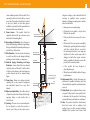
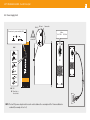
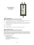
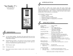
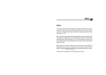
Ref. 563701 EN HDTV TRANSMODULATOR - Dual 8PSK to QAM User manual w w w. t e l e v e s . c o m HDTV TRANSMODULATOR - Dual 8PSK to QAM Contents 5 7 7 8 11 12 13 15 19 26 27 29 37 38 40 41 42 43 45 EN ENGLISH 1. Safety instructions ............................................................................................................................. 2. Description ........................................................................................................................................ 3. Main features ..................................................................................................................................... 4. Technical Specifications ..................................................................................................................... 5. Ordering information ......................................................................................................................... 6. Quick start guide ............................................................................................................................... 7. Product description ........................................................................................................................... 8. Installation .......................................................................................................................................... 9. Instructions for use ............................................................................................................................ 10. Distribution Bandwidth considerations .............................................................................................. 11. Firmware Updates ............................................................................................................................. 12. TSuite - CDC SOFTWARE ................................................................................................................. 13. Example installation ........................................................................................................................... 14. Rackmount Standards ....................................................................................................................... Appendix 1. CATV QAM channel frequencies ......................................................................................... Appendix 2. DISH NetworkTM Transmodulator Auto-Detect Code/Symbol Rates ................................ Appendix 3. DISH NetworkTM DBS - Anik F3 - FSS 121 _ FSS 105 Tables ........................................... Appendix 4. Programming unit Menus and Sub-menus ......................................................................... Appendix 5. Typical DISH NetworkTM Western Arc System ................................................................... 5 1 - Safety instructions A product and cart combination should be moved with care. Quick stops, excessive force and uneven surfaces may cause the product and cart combination to overturn. Caution statements Product inspection - Inspect the equipment for shipping damage. Should any damage be discovered, immediately file a claim with the carrier. The lightning flash with arrow head symbol, within an equilateral triangle, is intended to alert the user to the presence of uninsulated “dangerous voltage” within the product’s enclosure that may be of sufficient magnitude to constitute a risk of electric shock to persons. Important Safety Instructions - To ensure proper installation and operation, take a moment to read this guide before proceeding with the installation. If you have any questions or comments about the T.0X Series - HDTV TRANSMODULATOR - Dual 8PSK to QAM, please contact your dealer. WARNING: TO PREVENT FIRE OR ELECTRICAL SHOCK DO NOT EXPOSE TO RAIN OR MOISTURE. CAUTION: TO REDUCE THE RISK OF ELECTRIC SHOCK, DO NOT REMOVE COVER. NO USER-SERVICEABLE PARTS INSIDE. REFER SERVICING TO QUALIFIED PERSONNEL. The exclamation point within an equilateral triangle is intended to alert the user to the presence of important operating and maintenance (servicing) instructions in the literature accompanying the product. WARNING: TO REDUCE THE RISK OF FIRE OR ELECTRIC SHOCK, DO NOT EXPOSE THIS PRODUCT TO RAIN OR MOISTURE. DO NOT OPEN THE CABINET, REFER SERVICING TO QUALIFIED PERSONAL ONLY. CAUTION: TO PREVENT ELECTRIC SHOCK, DO NOT USE THIS (POLARIZED) PLUG WITH AN EXTENSION CORD RECEPTACLE OR OTHER OUTLET UNLESS THE BLADES CAN BE FULLY INSERTED TO PREVENT BLADE EXPOSURE. Important Safety Instructions 1. Read and Follow All Instructions - All the safety and operating instructions should be read prior to and followed while operating this product. 2. Retain Instructions - The safety and operating instructions should be retained for future reference. 3. Heed Warnings - All warnings on the product and in the operating instructions should be adhered to. 4. Cleaning - Disconnect this product from any electrical source before cleaning. Use a damp cloth; do not use liquid or aerosol cleaners. 5. Attachments - Do not use attachments that are not recommended by the product manufacturer as they may cause hazards. 6. Water and Moisture - Do not use this product near any source of water. 7. Mounting – Do not place this product on an unstable cart, stand, tripod, bracket, or table. The product may fall, causing serious injury to persons or nearby objects, and serious damage to this product. Use only with a cart, stand, tripod, bracket, or table recommended by the manufacturer, or sold with the product. Any mounting of the product should follow the manufacturer’s instructions, and should use a mounting accessory recommended by the manufacturer. 8. Ventilation – Slots and openings in the cabinet are provided for ventilation and to EN HDTV TRANSMODULATOR - Dual 8PSK to QAM 6 ensure reliable operation of the product. These openings should never be blocked or covered in any way. This product should not be placed in any case, cabinet, or rack unless proper ventilation is provided and the manufacturer’s instructions have been adhered to. 9. Power Sources - This product should be operated only from the type of power source indicated on the marking label. dangerous voltage or other hazards. Refer all servicing to qualified service personnel. Examples of damage requiring service include but are not limited to: yy Damage to power-supply wiring. yy If liquid has been spilled, or objects have fallen into the product. Satellite dish mast yy If the product has been exposed to rain or water. 10. Grounding or Polarization - Do not bypass or defeat electrical plug polarization or grounding. Doing so will violate the warranty and may pose a risk of fire or electrocution. 11. Wire Protection – Ensure all connected wiring is routed correctly to avoid damage including pinching, excessive bends, or compression. 12. Electrical Supply, Grounding, and Surge Protection – Ensure that all local or national electrical codes are followed. Seek the advice of a licensed electrician, professional engineer, or other licensed expert. See example wiring figure. 13. Power Lines - Always use caution and avoid operating this or any connected equipment near uninsulated power line or any other hazards. 14. Object and Liquid Entry - Never allow objects or liquid of any kind into this product through openings. Doing so could result in fire or electric shock. 15. Servicing - There are no user serviceable parts. Do not attempt to service this product or remove covers. Doing so may expose you to Mast ground clamp Coaxial cable Ground wires NEC Section 810-21 yy If the product does not operate normally by following the operating instructions. Adjust only those controls that are covered by the operating instructions as an improper adjustment of other controls may result in damage and will often require extensive work by a qualified technician to restore the product to its normal operation. yy If the product has been dropped or physically damaged. Electric Service Equipment Ground clamps Earthing pit Power Service Grounding Electrode System NEC Art. 250, Part H Rod Antenna Discharge Unit NEC Section 810-20 Home input yy When the product exhibits a distinct change in performance. 16. Replacement Parts - Ensure that repairs are performed by qualified technicians and that only manufacturer supplied or authorized parts are used. 17. Safety Check - Upon completion of any service or repairs to this product, ensure safety checks to determine that the product is functioning per manufacturer specifications are performed. 18. Heat - The product should be situated away from heat sources such as radiators, heat registers, stoves, or other products (including amplifiers) that produce heat. Ensure that 7 ambient temperature is maintained in the manufacturer specified operating range. 2 - Description yy The T.0X Series is a complete family of digital cable headend products. These products include satellite QPSK and 8PSK to QAM transmodulators, universal modulators and fiber optic transmitters/receivers, amplifiers, and splitters. The T.0X family of products all fit in a standard 19” rack chassis that contains a power supply and room for 7 modules. yy Each of the T.0X Q/8PSK modules contain 2 completely independent transmodulators that are capable of being fed from either the same or different sources with output frequencies able to be set independently across the entire range in order to provide maximum flexibility. yy The entire transponder’s multiplex is converted to a single QAM channel so all content regardless of whether it is video or music, MPEG2 or MPEG4, SD or HD, encrypted or not, will be output unaltered eliminating the need for additional costly encoding or encryption equipment in the headend. yy Additionally, both inputs and outputs can be daisy-chained with the input/output of a module being added to the input/output of all the preceding modules thus eliminating the need for RF splitters and combiners. yy Configuration and Control of the modules can either be done through the handheld controller or from any Internet connection with the use of the CDC headend controller module. The remote control of the system provides two easy to use options with the TSuite computer application or through any internet browser for maximum customer choice. 3 - Main features yy TWIN modules (two independent tuners per module) allowing up to 14 transcoded transponders/channels per chassis. yy User friendly interface allowing simple selection of which satellite transponder is output on which QAM channel including a decoded view of the satellite tables, output channel mode, and DISH NetworkTM installation mode. yy Two completely independent and fully agile outputs from 57 to 999 MHz (EIA Ch. 2-158) for easier organization of wider-than-6MHz QAM carriers. yy Input switching matrix allows for either of the two inputs to be routed to either demodulator including either one of the two inputs routed to both of the demodulators simultaneously. yy Up to 1024QAM output capability. yy Remotely upgradeable firmware allows for future updates without having to visit the headend. yy Carrier wave and null packets output mode for easy system balancing without an input signal or without a digital meter. yy Extensive monitoring information for easy troubleshooting (current and lowest input SNR, current and highest temperature reached, number of lock loss conditions over a period of time, etc.) with LED indicators on the front of the unit. yy Back-lit LCD display handheld programmer or TSuite PC application options for both on-site and remote configuration and troubleshooting. yy Copy configurations from one module to another with the handheld programmer for fast and easy module swaps (copy/paste). yy Web page configuration and remote management using the CDC system, including “DISH mode” for easy set-up. yy Input/Output daisy-chain architecture to avoid external splitters/ combiners. yy High performance, MER>40dB over the full frequency range of 57-999MHz. yy High output level, greater than 38 dBmV with over 20dB of attenuation margin for easy balance and integration. EN HDTV TRANSMODULATOR - Dual 8PSK to QAM 8 4. Technical Specifications 4.0 Block diagram PORT 1 PORT 2 Input Stage Demodulator A QAM Modulator A Up-converter A Demodulator B QAM Modulator B Up-converter B Output Stage QAM Output 4.1 8PSK to QAM transmodulator Table 1 . Technical specifications Input selection options Input frequency (agile) SEE TABLE 2 MHz Symbol rate 950 - 2150 Mbaud QPSK Legacy FEC Frequency steps Satellite input QAM Modulator RF Output General MHz 1 dBm QPSK Legacy (EN300421) Turbo 8PSK - Turbo QPSK -70 to -20 PORT1-PORT2 isolation dB > 25 (1) Loop-through losses dB < 1.5 Input modulation Input level Modulation format QAM Frequency range (agile) MHz Frequency steps MHz Output level dBmV Adjustable level (min.) dB Powering voltage Vdc Protection index IP 16, 32, 64, 128, 256, 512, 1024 57 ··· 999 (EIA Ch 2 to 158) 1 38 ± 2 20 24 20 (1) When using dual inputs, input signals should be correctly balanced to avoid undesired results. 8PSK Transmission filter Roll-off Factor In/Out connectors Input impedance Symbol rate (max) Roll-off factor Loop-through losses MER In/Out connectors Out Impedance Consumption 24V Working temperat. 10-30 Viterbi 1/2, 2/3, 3/4, 5/6, 7/8 Reed Solomon (204, 188) Interactive Turbo Error Correction Reed Solomon (204, 188) Square Root Raised Cosine % QPSK legacy 8PSK-TC QPSK-TC 35 20 type “F” female ohm 75 Mbaud 6.9 % 15 (12 for 1024 QAM) dB < 1.5 dB > 40 type “F” female. ohm 75 mA 600 ºF <113 (use forced ventilation at higher temp) 9 4.2 Satellite input options Table 2 . Satellite input options Option no. PORT 1 PORT 2 Port function TUNER A TUNER B Simplified diagram Signal from Comments PORT 1 TUNER A IN 1 IN OUT PORT 1 PORT 1 loop SWITCHING MATIRX TUNER B OUT PORT 2 Normal input mode. The input signal loop-through allows to daisy-chain the whole subrack avoiding the use of an external splitter. In this configuration the input signal connected to PORT1 feeds both tuners. PORT 1 TUNER A IN 2 IN IN PORT 1 SWITCHING MATRIX PORT 2 Independent inputs. TUNER B IN PORT 2 PORT 1 3 DISABLED IN PORT 2 PORT 2 TUNER A PORT 1 is disabled. TUNER B In this configuration the input signal connected to PORT2 feeds both tuners. SWITCHING MATIRX IN PORT 2 EN HDTV TRANSMODULATOR - Dual 8PSK to QAM 10 4.3 Broadband Amplifier Table 3 . Technical Specifications Frequency range Amplifier ref 5575 MHz 54 to 862 Connector type Gain dB 44 ± 2.5 Powering voltage Vdc 24 Regulation margin dB 20 Consumption at 24 Vdc mA 450 dBmV 45 Test socket dB -30 Mains voltage V~ 108 to 132 Mains frequency Hz 50/60 Current consumption (max.) A~ Working temperature (max.) ºF Output level “F” 4.4 Power Supply Unit Table 4 .- Technical Specifications Power Supply Unit ref 563901 (1) Provides protection voltage variation from 21 to 27 V= Output voltage V= 24±1 (1) Output current (max.) A= 5(2) 1.5 Output power W 113 Protection level 120 IP20 (2) Maximum current limited to 4A= 4.5 Power consumption Table.- Power consumption vs number of units Table.- Power consumption vs number of units&CDC Chassis load Power consumption (W) IAC (mA) Chassis load Power consumption (W) IAC (mA) 1 555902 + 1 × 563701 21.1 203 1 x 563701 20.5 197 1 555902 + 2 × 563701 32.5 291 2 x 563701 32 287 1 555902 + 3 × 563701 44.4 390 3 x 563701 43.7 381 1 555902 + 4 × 563701 56.2 484 4 x 563701 55.8 479 1 555902 + 5 × 563701 68.2 584 5 x 563701 67.6 579 1 555902 + 6 × 563701 80.3 685 6 x 563701 80 682 7 x 563701 93.3 813 11 5. Ordering information When ordering, please, specify reference number as per table below. Ref # Description Ref # Description SMATV 234501 T.0X Optical Splitter, 16 ways 563901 T.0X Power Supply Unit (110 Vac/UL) 234601 T.0X Optical Splitter, 32 ways 563701 T.0X 8PSK/QAM TWIN Transmodulator 233501 T.0X Optical Receiver 555902 T.0X CDC IP Headend Manager 233601 T.0X Optical Receiver / Return Path Transmitter (1310nm / 6dBm) 5806 T.0X Universal TWIN Modulator 5575 Broadband amplifier FIBER OPTICS 233311 T.0X Optical Transmitter (1310nm / 10dBm) 233411 T.0X Optical Transmitter (1310nm / 10dBm) / Return Path Receiver 234305 T.0X Optical Transmitter (1550nm / 4dBm) 234311 T.0X Optical Transmitter (1550nm / 10dBm) 234220 T.0X EDFA Optical Amplifier (20dBm) 2337 T.0X Optical Splitter, 2 ways 2339 T.0X Optical Splitter, 4 ways 234401 T.0X Optical Splitter, 8 ways 2310 Outdoor Optical Receiver/Amplifer w/ Return Path Transmitter (1310nm / 3dBm) 2311 FTTU Mini Optical Receiver ACCESSORIES 7234 Handheld Programming Unit 5301 19in Chassis, 7 modules+1PSU 422603 Control Bus Jumper (40 inches) 140057 Power Bus Jumper (15 inches) EN HDTV TRANSMODULATOR - Dual 8PSK to QAM 12 6. Quick start guide 5. I nterconnect the units with the power and control bus jumpers supplied before applying power to the system. Use the long control bus jumpers to connect different subracks together. - Each PSU output provides up to 4A and both must be used in order to balance the HDTV TRANSMODULATOR - Dual 8PSK to QAM HDTV TRANSMODULATOR - Dual 8PSK to QAM HDTV TRANSMODULATOR - Dual 8PSK to QAM HDTV TRANSMODULATOR - Dual 8PSK to QAM 8. E ach subrack should be treated as a standalone module in terms of power and RF output. - Each daisy-chained output does incur some loss. - Balance the final output of the subrack appropriately. - Use an external combiner to combine the outputs of all subracks together. CONTROL BUS CONNECTORS 6. C onnect the supplied RF input and output coax bridge bars as needed. HDTV TRANSMODULATOR - Dual 8PSK to QAM HDTV TRANSMODULATOR - Dual 8PSK to QAM POWER CONNECTORS HDTV TRANSMODULATOR - Dual 8PSK to QAM PORT2 HDTV TRANSMODULATOR - Dual 8PSK to QAM HDTV TRANSMODULATOR - Dual 8PSK to QAM 4. Arrange the PSU and units of each subrack from left to right, starting by the PSU, followed by the CDC. Remote Headend Controller (if used) and the transmodulators. WARNING: Unterminated input and output ports are a common source of ingress noise. Be sure to terminate all unused input and output ports with 75 ohm loads (ref. 4061) for optimum performance. WARNING: Never connect control bus jumpers to power connectors or vice versa. Doing so will cause PORT1 irreparable damage to the units when power is applied. HDTV TRANSMODULATOR - Dual 8PSK to QAM 3. U npack the units and the PSU. Check that all accessories such as jumpers, coax bridge bars, power cords, etc., have been provided. If not, contact your distributor immediately. 7. B e sure that all connections are secured, properly terminated and tightened before applying power to the system. 9. P roceed with the configuration of each unit as detailed in this User Manual. HDTV TRANSMODULATOR - Dual 8PSK to QAM efore installing the units, take into account 2. B the 19” subrack is 5RU height, so size rack appropriately. A 1RU spacing plate is recommended between every 2 subracks for easier wiring access. HDTV TRANSMODULATOR - Dual 8PSK to QAM 1. The headend must be installed in a well ventilated room, free of humidity and with the necessary facilities. Forced ventilation or an HVAC system will need to be installed when ambient temperature is over 113ºF at the headend location. HDTV TRANSMODULATOR - Dual 8PSK to QAM HDTV TRANSMODULATOR - Dual 8PSK to QAM consumption of the 7 transmodulators in a subrack (for example: 4+3 or 3+4). HDTV TRANSMODULATOR - Dual 8PSK to QAM WARNING: Do not apply power to the headend until all the connections have been completed and double checked. Failure to do so may result in irreparable damage to the equipment. - Start by configuring the inputs of each unit to the desired satellites/transponders. - Set the output level accounting for the losses due to the unit’s loop-through. - If remote control is used, follow the instructions in the corresponding User Manual of the CDC Remote Headend Controller. 13 7. Product description 7.1. Introduction The HDTV TRANSMODULATOR - Dual 8PSK to QAM allocates the information contained in two independent satellite transponders (QPSK legacy, Turbo QPSK or Turbo 8PSK modulations) in two completely independent cable channels in the 57 to 999MHz range (Ch. 2 to 158). The digital transmodulation process starts with the demodulation of the input satellite transponders, to obtain the MPEG2 transport streams which are then remodulated into QAM format. the output signal of previous modules installed in the same subrack. The universal Programming Unit (ref. 7234) is used to program the operating parameters of the HDTV TRANSMODULATOR - Dual 8PSK to QAM unit. 7.2. Front panel elements description The next figure shows the location of all the ports, status and alarm indicators, existing in the front on the unit. PORT1 and PORT2 are the satellite input F-connectors (see table 2 for configuration options). The input signal can be daisy-chained to all the modules in a subrack, thus minimizing the use of external splitters. Connector 3 is the daisy chain QAM input from a previous QAM output. Connector 4 outputs the combined QAM output. Loop-through losses are very low allowing to combine the output of all the units in a subrack. The HDTV TRANSMODULATOR - Dual 8PSK to QAM features two F-type satellite input connectors labelled PORT1 and PORT2, allowing 3 input configuration options (table 2): 5 6 • PORT1 routed to both tuners A and B (A loopthrough output is available in PORT2). HDTV TRANSMODULATOR - Dual 8PSK to QAM The output channel bandwidth will depend on the useful bitrate of the satellite transponder and the modulation selected for the QAM output. PORT1 PORT2 10 • PORT1 routed to tuners A and PORT2 to tuner B (Two independent inputs). 7 12 • PORT2 routed to both tuners A and B (PORT1 is not used). The HDTV TRANSMODULATOR - Dual 8PSK to QAM unit also features two output RF connectors, the bottom one is the QAM output and the top one is the QAM input (loop-through) that allows to mix 8 Side view Front view 9 11 1. PORT1 – Satellite L-Band input 2. PORT2 – Satellite L-Band input/output 3. RF QAM input (loop-through input) 4. RF QAM output (loop-through output) 5. Power bus connectors 6. Control bus connectors 7. Computer/Programmer connector 8. Temperature status LED 9. SAT A input status LED 10. QAM A output status LED 11. SAT B input status LED 12. QAM B output status LED EN HDTV TRANSMODULATOR - Dual 8PSK to QA PORT1 HDTV TRANSMODULATOR - Dual 8PSK to QAM PORT2 The unit also features 2 sets of daisy-chain connectors for the power and control buses. Special care must be taken so as to never connect control bus jumpers to power connectors or vice versa. Doing so will cause irreparable damage to the units. Connector 7 is the handheld programmer unit (ref. 7234) connection. HDTV TRANSMODULATOR - Dual 8PSK to QAM Front light indicators 8 to 12 are alarm/status LEDs that give monitoring information about the unit status, as follows: PORT1 PORT2 14 Table 5.- FRONT UNIT LED ALARMS TEMPERATURE (LED no. 8) LED Colour Unit internal temperature (ºF) Comments Solid green under 149 SAFE Slow blink orange between 149 ···185 WARNING Fast blink red over 185 OVER TEMP SATELLITE INPUT STATUS - for A and B tuners (LEDs no. 9 &11) LED Color Tuner status Comments Solid green LOCKED Good input SNR Solid orange LOCKED Low input SNR Solid red UNLOCKED MANUAL mode UNLOCKED & SCANNING Fast blink red INPUT SIGNAL QAM OUTPUT SIGNALS (LEDs no. 10 &12) AUTO mode QAM channel status Comments Solid green LOCKED NORMAL mode Fast blink green SPECIAL MODE CW, MUTED, & NULL modes Solid orange OVERFLOW MANUAL mode Fast blink orange OVERLAP between QAM output carriers LED Color Solid red UNLOCKED - Fast blink red DEACTIVATED RAINFADE CONDITION 15 8. Installation 8.1 - 19” subrack mounting EN HDTV TRANSMODULATOR - Dual 8PSK to QAM 16 8.2 Power Supply Unit M4x10 Connectors to power modules (24V ) M4 nut Star washer Mains 108 - 132V~ 50/60Hz Grounding connection LEDS 24V: OK 0V: Overload or short circuit NOTE: T he two PSU power outputs must be used in order to balance the consumption of the 7 transmodulators in a subrack (for example: 4+3 or 3+4) 17 8.3 Broadband Amplifier Ref. 5575 1. 2. 3. 4. RF output Test output RF input 1 RF input 2 5. 6. 7. Power input Status LED Attenuator adjustment This unit features two RF input connectors (3 & 4), to allow mixing signals coming from two different systems or subracks. When only one of the two inputs is used it is advisable to terminate the unused input port with a 75 ohm load (ref 4061). As with all T.0X units, this amplifier is powered via the 24 Vdc power bus. The unit combines and amplifies input signals in the 54-862 MHz frequency band. EN HDTV TRANSMODULATOR - Dual 8PSK to QAM 18 8.4. Programming Unit The handheld programmer has an LCD display, three LED indicators and four buttons: PCT UNIVERSAL Table 8 .- Programmer key functions Key A B Keystroke short Enable / Disable “Edit mode” Move Cursor in “Edit mode” long Default configuration Reset unlock counters Reset minimum SNR Reset maximum temperature short Change parameter value (when in “Edit mode”). Change menu (when not in “Edit mode”). short Change menu type A, B or C long Save changes to memory long Increase screen contrast C + + + + Function description long Decrease screen contrast + long Copy configuration (see page 25) + long Paste configuration (see page 25) 19 9. Instructions for use PCT UNIVERSAL A B C The first item displayed after connecting the Programming Unit to the front of the transmodulator is the Programming Unit’s firmware version: PCT firmware version -----------V:5.03.00001 Sub-menu 1 Sub-menu 1 Sub-menu 1 Sub-menu 2 Sub-menu 2 Sub-menu 2 ▲ ▲ ▲ ▼ ▼ ▼ Sub-menu N Sub-menu N Sub-menu N The configuration screens are organized in three main sections as shown in the figure (refer to Appendix 4 for a detailed diagram): • Section A: MAIN MENUS • Section B: CONFIGURATION MENUS • Section C: MONITORING MENUS LEDs A, B and C will light up indicating the currently selected section. The ■ button toggles between sections. To move up and down a section press the ▲ and ▼ buttons . To save data, press and hold the ■ button. In each individual screen, pressing the ● button enables the “Edit mode” and the selected parameter can then be modified by using the ▲ or ▼ buttons. In those cases where the cursor may be placed in more than one position (for example an input frequency with several digits) press the ● button as many times as needed to position the cursor over the desired field. To move to a different screen, press the ● button until the cursor stops blinking (cursor is OFF, leaving “Edit mode”). Each screen displays and allows the modification of a single operating parameter, which is described by a short message on the display. 9.1 - MAIN menu (LED A is ON) Transcoder selection The first menu allows the selection of one of the unit’s tuners, A or B. Once selected, the remaining submenus in this section will refer to the parameters of the selected tuner. SELECT TRANSCODER SELECT TRANSCODER TUNER A TUNER A Press the ● button to enter “Edit mode” so the last line of the display starts to blink (cursor ON). You can now select one of the tuners (A or B) using the ▲ and ▼ buttons. To exit “Edit Mode” press the ● button until the cursor stops blinking (cursor OFF) Satellite selection This menu only appears when transponder mode has been selected in the corresponding CONFIGURATION menu (see pag 20) and allows the selection of one of the predefined satellites. - TUNER A SELECT INPUT SATELLITE 61.5º EAST The current list of pre-defined DISH NetworkTM satellites is detailed in Appendix 3: EN HDTV TRANSMODULATOR - Dual 8PSK to QAM Slot 61.5º 72.7º 77º 110º 119º 129º 118.7º 121º 105º E/W EAST EAST EAST WEST WEST WEST WEST WEST WEST Sat ID DBS DBS DBS DBS DBS DBS Anik F3 FSS 121 FSS 105 Input frequency/transponder selection Use this menu to select the input frequency, either by entering the frequency value in MHz or the transponder number, depending on the selected mode (MANUAL, XPNDR STACK or XPNDR LEGACY). The display will show the following information in each case: - TUNER A SELECT INPUT FREQUENCY 1500 MHz - TUNER A SELECT INPUT TRANSPONDER 1R= 974MHz Press circle to enter the “Edit mode” and the last line of the display will start to blink (cursor ON). In manual mode (setting by frequency), you can move the cursor to any of the 4 frequency digits by pressing the ● button. In transponder mode, the transponder’s number will blink displaying the corresponding L-Band input frequency . 20 Input modulation selection This menu only appears when the user has selected the manual modulation mode in the corresponding CONFIGURATION menu. - TUNER A SELECT INPUT MODULATION TQPSK 7/8 In this case the user has to manually select the input modulation, the available choices are: QPSK Scan 8PSK 2/3 8PSK 3/4 8PSK 4/5 8PSK 5/6 8PSK 8/9 TQPSK 1/2 TQPSK 2/3 TQPSK 3/4 TQPSK 5/6 TQPSK 7/8 Input baud rate selection This menu only appears when the user has selected the manual modulation mode in the corresponding CONFIGURATION menu. In this case the user has to manually enter the baudrate of the input signal (between 10,000 and 30,000 Kbaud). - TUNER A SELECT INPUT SYMBOL RATE 22.000 Kbaud Output frequency/ channel selection This menu allows the user to select the output frequency/channel according to the mode selected in the corresponding CONFIGURATION menu. - TUNER A SELECT OUT CHANNEL 2 = 57MHz - TUNER A SELECT OUT FREQUENCY 57MHz (2) In channel mode, the CATV QAM channel is selected (see Appendix 1). The last line of the display will show both the output channel number and its center frequency (Channel # = center frequency). In frequency mode, the user can select any frequency value between 57 and 999 MHz and the corresponding channel number is displayed between brackets. The two outputs in an HDTV TRANSMODULATOR - Dual 8PSK to QAM are completely agile, so the two QAM channels can be positioned anywhere in the spectrum allowing for maximum flexibility. 21 Output modulation selection This menu only appears when the user has selected the manual modulation mode in the corresponding CONFIGURATION menu, in this case the user has to manually select the constellation of the QAM output signal (between 16, 32, 64, 128, 256, 512 and1024 QAM): - TUNER A SELECT OUT MODULATION 256 QAM If the QAM order selected is not able to accommodate the data rate of the input signal, it will cause an overflow condition. This will be indicated on the display with the OVF! alert text after the selected QAM modulation and an orange LED in the front of the unit. - TUNER A SELECT OUT MODULATION 16QAM OVF! Output level selection This menu lets you select the QAM channel output level, between 00 and 99. A setting of “99” means no attenuation is applied to the output and thus the output level is the maximum (38 ± 2dBmV). A setting of “00” means the output level is attenuated by 20 dB (approx.) below its maximum output level. By changing this value the user can select the amount of attenuation applied and therefore balance the system as needed. - TUNER A SELECT OUT LEVEL 69 Output mode selection Use this menu to select the desired output mode: - TUNER A SELECT OUT MODE NORMAL - NORMAL: The output signal is a QAM transmodulated version of the input satellite signal. This is the normal functioning mode. -N ULL: Null packets are modulated. This mode generates a well-formed QAM output carrier even when the demodulator is not locked and can be used to balance the system in absence of input signal (off-site). -M UTED: There is no output signal. This mode can be used to turn off the output of certain channels or to leave hot spares prepared in the headend. -C ARRIER WAVE: The unit generates an unmodulated carrier wave on the output frequency that has the same level as the power of the corresponding QAM carrier. This mode can be used to balance the RF output levels with a simple SLM when a QAM digital meter is not available. 9.2 - Configuration menus (LED B is ON) This section includes a number of less frequently used configuration options and is indicated by LED B on the Programming Unit. Input routing mode Use this menu to select the routing of the input signals (details on Table 2 on page 41): SELECT TUNER INPUT CONFIG A = PORT 1 B = PORT 2 A = PORT 1 B = PORT 1 (PORT 2 is a loop-through output of the signal connected to PORT 1) A = PORT 1 B = PORT 2 (Dual inputs) A = PORT 2 B = PORT 2 (PORT 1 is disabled and cannot be used) EN HDTV TRANSMODULATOR - Dual 8PSK to QAM Modulation mode This menu allows the selection of the input modulation mode. In “Auto Detect” mode, the input/output modulation parameters are set automatically according to the priority look-up table in Appendix 2. SELECT MODULATION MODE AUTO DETECT In “Manual” mode, the user has to manually configure all the modulation parameters. Input frequency mode Using this menu the user can select one of the modes available to program the input frequency: SELECT INPUT FREQ MODE XPNDR STACK - MANUAL: The user has to manually enter the input L-Band frequency in MHz. - XPNDR LEGACY: The user selects the satellite and transponder and the unit automatically calculates the input frequency for a DISH legacy LNB (non stacking). - XPNDR STACK: The user selects the satellite and transponder and the unit automatically calculates 22 the input frequency for a DISH PRO stacking LNB. Output frequency mode Using this menu, the user can select one of the two modes available to program the output frequency: SELECT OUT FREQ MODE CHANNEL - CHANNEL: The user selects an output channel between 2 and 158 according to the CATV QAM channel frequencies in Table 1 ( Appendix 1). - MANUAL: The user has to manually enter the output CATV frequency in MHz. Remote control address Use this menu to change the remote control address when the unit is connected to a CDC Remote Headend Controller (ref. 555902) via its control bus. It is the user’s responsibility to ensure that each unit in the bus has been assigned a different and unique address in the bus. SELECT REMOTE CTRL ADDRESS 001 The valid address range goes from 1 to 254 (maximum number of devices controllable from a single headend controller module). WARNING: Duplicated addresses will cause data collision on the bus and the transmodulators will not be able to communicate with the Remote Headend Controller. Restore default settings To return the unit to its default factory configuration enter this menu and then press and hold down the ● button for a few seconds. SELECT DEFAULT SETTINGS HOLD ● key The Programming Unit will display the following message: Restoring default values ... Once finished it will go back to the first MAIN menu (transcoder selection). WARNING: The remote control address parameter will default to 1 after restoring the unit to factory settings. 23 9.3 - MONITORING menus (LED C is ON) This set of menus displays firmware versions and monitoring information, and is indicated by LED C on the Programming Unit. Versions menu This menu displays the unit’s reference number, Firmware and FPGA (QAM Modulator) versions and the auto look-up table version for modulation “Auto Detect” mode. Ref: 563701 FW: 1.00.0009 FPGA:1.00.04 AUTO:1.03 Input status This menu displays the status of the input signal, indicating its lock status. When locked, the detected input modulation and symbol rate are displayed. - INPUT A STAT: LOCKED MOD:QPSK-2/3 SR: 27.500Kb - INPUT A STAT: UNLOCKED If “Auto Detect” modulation mode is selected, the word SEARCHING will blink on the display as the unit tries to acquire an input signal when the demodulator is not locked. - INPUT A STAT: UNLOCKED SEARCHING Output status This menu displays the status of the output signal, indicating the output QAM constellation, the QAM symbol rate and the bandwidth occupied by the output carrier. - OUTPUT A MOD: 1024QAM SR: 3.667Mb BW: 4.107MHz - OUTPUT A MOD: 1024QAM QAM Unlock - OUTPUT A MOD: 64 OVF SR: 6.111Mb BW: 7.028MHz When the bandwidth of the two output signals generated by the QAM transmodulator and their frequencies are such that overlap each other, it is indicated by the message OVERLAP!. - OUTPUT A MOD: 256QAM SR: 4.583Mb OVERLAP! When the input SNR falls below a certain modulation dependent threshold (rain fade), the output QAM signal is muted to avoid artifacts in the reception and the message “RAIN FADE!” is displayed. - OUTPUT A QAM Unlock If “Auto Detect” modulation mode is selected, and if the tuner is not locked, the QAM modulation will not be displayed, because it will depend on the input signal acquired. If the QAM constellation manually selected is not enough to accommodate the data rate of the input signal, it will cause an overflow condition, and OVF will be displayed. Input measurements This menu displays the current input SNR, the minimum input SNR recorded, and the number of tuner unlock conditions. SNR TUNER A NOW: 11.5dB MIN: 3.5dB #Unlock: 03 EN HDTV TRANSMODULATOR - Dual 8PSK to QAM The minimum SNR and unlock counters can be reset by pressing and holding the ● button for approximately 2 seconds. These values are stored in nonvolatile memory so they are not erased otherwise, even when the unit loses power or is turned off. Any change to the input parameters (frequency, baud rate, satellite, etc.) automatically resets these counters. Temperature menu This menu shows the current internal temperature and the maximum internal temperature recorded (F). The maximum value is stored in nonvolatile memory for monitoring purposes. - TEMP NOW: 103ºF MAX: 125ºF - TEMP NOW: 193ºF MAX: 195ºF WARNING TEMP If the current internal temperature exceeds 149ºF (65ºC) the screen will display the message “WARNING TEMP”. If the current internal temperature exceeds 185ºF (85ºC) the screen will display the message “OVER TEMP” The maximum registered temperature may be reset by pressing and holding the circle button for a few seconds. 24 25 9.4 - Configuration Copy/Paste using the Programming Unit To enter copy/paste mode, press and hold the ● and ▼ buttons at the same time from any MAIN menu. Then follow the flowchart below to copy/paste configurations to/from the handheld Programming Unit. EN HDTV TRANSMODULATOR - Dual 8PSK to QAM 26 10. Distribution Bandwidth considerations The bandwidth of a transmodulated QAM signal depends on the parameters of the incoming satellite signal (baud rate, modulation and FEC) and on the QAM constellation selected for the output carrier. For the same parameters of the satellite signal, the higher the QAM order, the narrower the QAM signal is. As an example, in automatic mode, an input baud rate and satellite modulation signal (8PSK 2/3 21.5MBaud) is transmodulated to 256QAM carriers occupying bandwidths up to 6.43MHz. Lower input baud rate signals are transmodulated to 64QAM or 128QAM carriers with narrower bandwidths up to 5.75MHz. Whenever channel bandwidth is wider than 6 MHz, there is an overlap of the 2 adjacent channels In order to avoid this overlapping it advisable to alternate narrow 64/128 QAM carriers with wider 256 QAM carriers in the distribution, as in the example below: 64 / 128 QAM output Bandwidth up to 5.75 MHz 256 QAM output Bandwidth up to 6.43 MHz Standard American CATV channels have 6 MHz of bandwidth, therefore, 256 QAM modulated signals with a bandwidth wider than 6 MHz can cause interference to the adjacent channels. Two 256 QAM carriers on adjacent channels can cause a 3 dB MER degradation. While some satellite input signals may be transmodulated to 1024QAM carriers that are less than 6 MHz, it is still recommended to alternate narrow 64/128 QAM carriers in the same fashion. It is also recommended to set the output level of the 1024 QAM carrier to be 2-3 dB greater than the adjacent carriers. These steps are recommended due to the increased sensitivity to interference in 1024QAM signals. The fully agile and fully independent QAM outputs of the HDTV TRANSMODULATOR - Dual 8PSK to QAM greatly help to overcome this issue. 27 11. Firmware Updates Select English as preferred language if needed: Introduction Then click on “Update FPGA”: To update the Firmware of the unit you will need additional hardware and a software package: • USB - Serial Port adapter. • Cable DB-9 to RJ45. • PauTves software package. Unzip the PauTves tool to a known location and run the program: EN Verify the port configured in the program (“Configure Serial Port”) is the one you have your COM/SERIAL adaptor connected to: The program will detect the connected unit as a 563701: Press OK and the following window will appear: HDTV TRANSMODULATOR - Dual 8PSK to QAM 28 Select “Update FPGA” and browse for the .rbf file stored in your computer (see the example screenshot on the right). Click Open and the update will begin: When it is finished the following message will appear on the screen: If an unexpected failure occurs during programming, a default version of the firmware that is stored in the boot sector will get reloaded automatically, thus preventing a permanent failure. Repeat going back to the “Update FPGA” step to update more units. 29 12. TSuite - CDC SOFTWARE This software allows remote or local control of a T.0X headend, via a control module either ref. 5559 (CDC IP) or ref. 555901 CDC IP/GSM). Main features Steps to follow 1 Register a user account on Televés Services. 2 Once an account is created, login to Televés Services to register a T.0X • Compatible with T05 headends. CDC. The data required are the MAC and Serial Number of the module. • Adjustment, maintenance, control, management and monitoring of new T.0X headends from anywhere in the world via the internet. The control of a headend using the TSuite program can be done in three different ways: • Designed to support new services. uIn local mode, programming modules one by one performing the • Plug and play. • Allows the use of a PC as local programming unit. function with the Programming Unit. uIn local mode, programming the headend via the CDC module. uIn remote mode, programming the headend by using a CDC module TSuite offers, through Televés Services, a private portal for each user enabling centralized management of all headends. • Allows monitoring headend communication status. • Provides connection alerts and record of user sessions. Remote monitoring of a headend and connection to Televés Services An alternative to the TSuite software is the web based Televés Services. This web interface will allow you to check the status of and configure a headend. connected to the Internet. Whatever the method, it is necessary that each module has been assigned with different CDC addresses. Refer to section 8 for detailed instructions. EN HDTV TRANSMODULATOR - Dual 8PSK to QAM Using TSuite software in local mode, programming modules one at a time. 30 2 To set the port used, select Configuration, Serial communications. Preliminary considerations 1. The connection between the PC and the module to be configured is made via the serial port and a cable RS232 - RJ45. 2. If you do not have a serial port, you can use a USB-RS232 adapter ref. 5838. Steps to follow 1 When using a USB 2.0 RS-232 adapter (ref. 5838), check availability of the serial port, and make note of the active COM port. 3 Specify the port used in the drop down window and click Accept. 31 4 Activate the Identify Device function by selecting the icon in the menu bar. 6 The program will place a graphic of the module within a headend frame. EN 5 The program will identify the device connected, then select Add to a new headend. 7 Double clicking on the module opens its management window. You can now perform all the functions you would with the programmer. To do this, activate the Enable / Disable direct communication. HDTV TRANSMODULATOR - Dual 8PSK to QAM 8 There are 3 tabs, Status, Setup, and Advanced. A sample Status screen is shown. 9 Setup function: You can modify all the input and output parameters here. 32 10 Advanced functions allow you to change the address of the module. Using TSuite software in local mode, programming modules through the CDC. Preliminary considerations 1. Direct connection between the PC and the CDC module with a data cable RJ45-RJ45. 2. The transmission of information is done through a network interface. To do this, configure the computer’s IP to be on the network of IP CDC module. The CDC IP module can be configured by the programmer, but by default is 169.254.1.253. 33 Steps to follow 1 Assign the computer an IP address on the network of the CDC. 3 In Session Control box, select IP Connection, then Start session. Then select the name of the connection made in step 2. EN 2 Select New File with the icon or the menu File, New IP Connections, IP Connections management, select Create new connection and select the direct option (LAN) in the Connection Type. Then enter a name and the IP address of the CDC module. 4 Enter Password for the headend and select Apply. HDTV TRANSMODULATOR - Dual 8PSK to QAM 5 You will see the status screen as the session is started. 6 Once connected, you will see a graphic representation of the headend. 34 7 Double clicking on the CDC module displays the CDC management window. Selecting “Load modules connected to the CDC,” will load all modules connected to and recorded in the CDC. 8 Status will be displayed as the program is loading information for the modules. 35 9 Once all modules are loaded, a pop up “Headend loaded!” will be displayed. Using TSuite software in remote mode, programming modules through the CDC connected to the internet. Preliminary considerations 1. The connection between the CDC module and Internet can be accomplished in two ways: through a LAN; or using the GPRS modem built into a module ref. 555901. In the latter case, we need an active SIM card with a data plan. 2. If using a LAN, an internet connection is needed that does not block outbound ports. The CDC will connect to a Televés server and this connection 10 After exiting the CDC screen, all the recognized modules will be displayed. You can double click on a module to monitor or configure it in the same was as described in section “Using TSuite software in local mode, programming modules one at a time”. 3. will provide a link back to the CDC. Steps to follow 1 In IP Connections, IP Connections management, select create new connection, and select the Server option in the Connection Type. Then enter the Name and the MAC Address of the module (found on the label). 2 In Session Control box, select IP Connection, then Start session. Then select the name of the connection created in the previous step and enter the headend password. EN HDTV TRANSMODULATOR - Dual 8PSK to QAM 3 The rest of the steps are identical to the previous section. 36 563901 234305 234220 2337 234601 60 ADVANCE 7 X 563701 14 transponders HDTV TRANSMODULATOR - Dual 8PSK to QAM HDTV TRANSMODULATOR - Dual 8PSK to QAM HDTV TRANSMODULATOR - Dual 8PSK to QAM HDTV TRANSMODULATOR - Dual 8PSK to QAM OUTPUT (NOTE 3) F.O. Distribution (6) 234601 60 ADVANCE H60 HDTV TRANSMODULATOR - Dual 8PSK to QAM HDTV TRANSMODULATOR - Dual 8PSK to QAM HDTV TRANSMODULATOR - Dual 8PSK to QAM HDTV TRANSMODULATOR - Dual 8PSK to QAM HDTV TRANSMODULATOR - Dual 8PSK to QAM HDTV TRANSMODULATOR - Dual 8PSK to QAM HDTV TRANSMODULATOR - Dual 8PSK to QAM HDTV TRANSMODULATOR - Dual 8PSK to QAM HDTV TRANSMODULATOR - Dual 8PSK to QAM HDTV TRANSMODULATOR - Dual 8PSK to QAM Mixer HDTV TRANSMODULATOR - Dual 8PSK to QAM SAT 119º HDTV TRANSMODULATOR - Dual 8PSK to QAM QAM HDTV TRANSMODULATOR - Dual 8PSK to QAM 7 X 563701 14 transponders HDTV TRANSMODULATOR - Dual 8PSK to QAM HDTV TRANSMODULATOR - Dual 8PSK to QAM HDTV TRANSMODULATOR - Dual 8PSK to QAM HDTV TRANSMODULATOR - Dual 8PSK to QAM HDTV TRANSMODULATOR - Dual 8PSK to QAM HDTV TRANSMODULATOR - Dual 8PSK to QAM HDTV TRANSMODULATOR - Dual 8PSK to QAM HDTV TRANSMODULATOR - Dual 8PSK to QAM HDTV TRANSMODULATOR - Dual 8PSK to QAM HDTV TRANSMODULATOR - Dual 8PSK to QAM HDTV TRANSMODULATOR - Dual 8PSK to QAM HDTV TRANSMODULATOR - Dual 8PSK to QAM H60 (1) Analog bulk (2) HD digital content (3) Additional F.O. distribution (4) Regular coax distribution (5) 555902 Internet D, DEVELOPED & MANUFA CTURED BY TELEVE S COR POR ATION 7 X 563701 14 transponders HDTV TRANSMODULATOR - Dual 8PSK to QAM HDTV TRANSMODULATOR - Dual 8PSK to QAM HDTV TRANSMODULATOR - Dual 8PSK to QAM HDTV TRANSMODULATOR - Dual 8PSK to QAM HDTV TRANSMODULATOR - Dual 8PSK to QAM HDTV TRANSMODULATOR - Dual 8PSK to QAM 100% DESIGNED , DEVELOPED & MAN UFACTU RED BY TELEVE S CORPORATION 5559 100% DESIGN E 563901 HDTV TRANSMODULATOR - Dual 8PSK to QAM 563901 HDTV TRANSMODULATOR - Dual 8PSK to QAM HDTV TRANSMODULATOR - Dual 8PSK to QAM HDTV TRANSMODULATOR - Dual 8PSK to QAM 563901 HDTV TRANSMODULATOR - Dual 8PSK to QAM HDTV TRANSMODULATOR - Dual 8PSK to QAM HDTV TRANSMODULATOR - Dual 8PSK to QAM (SEE NOTE 5) UFACTURED BY TELEVES CORPORATION UFACTURED BY TELEVES CORPORATION 563901 DEVELOPED & MAN DEVELOPED & MAN NTSC 100 % DES IGNED, 100 % DES IGNED, 100% DESIGNED , DEVELOPED & MAN UFACTU RED BY TELEVE S CORPORATION DISH DISH DISH DISH 37 13. Example installation 60 ADVANCE H60 (NOTE 1) 5806 12 channels SAT 110º 60 ADVANCE 2311 Amplifier NOTES: Computer Tablets Smartphones Dish STB HDTV Dish STB HDTV Dish STB HDTV EN (NOTE 2) Existing MDU Coax QAM F.O. SAT 129º (NOTE 2) (NOTE 4) QAM (NOTE 2) (up to 64 FO) (NOTE 4) F.O. H60 60 ADVANCE HDTV TRANSMODULATOR - Dual 8PSK to QAM 38 14. Rackmount Standards (max. 49 - 7 subracks with 5RU height - 8’7”) 14.1. Installation of the rack with ventilation facilities To aid in cooling for proper operation, especially in warm locations (>113ºF ambient), installation of 2 25W or greater fans is recommended at the top of the rack. See fig 1 and 2. Be sure to leave approximately 3-5 cm of ventilation slots at the top for proper air flow. See fig 2 and 3. fig. 1 Front Subrack fig. 2 fig. 3 39 14.2. Installation of the rack without fans In order to provide adequate cooling, proper airflow must be established. As such, the following items must be observed: If fans are not available and the rack is installed in ambient temperatures near 113ºF, it is advisable to leave the rack sides completely open. See fig 5. - Do not open the side doors. This could cause fans to move air from outside rather than through the rack. EN - Do not place objects near the rack that could clog the ventilation inlets and outlets. - If the rack is not complete, the subracks must be placed from the top downwards without leaving large gaps in between, fig. 4. fig. 4 fig. 5 HDTV TRANSMODULATOR - Dual 8PSK to QAM 40 Appendix 1.- CATV QAM channel frequencies CH# 2 3 4 5 6 95 96 97 98 99 14 15 16 17 18 19 20 21 22 7 8 9 10 11 12 13 23 QAM center frequency (MHz) 57.00 63.00 69.00 79.00 85.00 93.00 99.00 105.00 111.00 117.00 123.00 129.00 135.00 141.00 147.00 153.00 159.00 165.00 171.00 177.00 183.00 189.00 195.00 201.00 207.00 213.00 219.00 CH# 24 25 26 27 28 29 30 31 32 33 34 35 36 37 38 39 40 41 42 43 44 45 46 47 48 49 50 QAM center frequency (MHz) 225.00 231.00 237.00 243.00 249.00 255.00 261.00 267.00 273.00 279.00 285.00 291.00 297.00 303.00 309.00 315.00 321.00 327.00 333.00 339.00 345.00 351.00 357.00 363.00 369.00 375.00 381.00 CH# 51 52 53 54 55 56 57 58 59 60 61 62 63 64 65 66 67 68 69 70 71 72 73 74 75 76 77 QAM center frequency (MHz) 387.00 393.00 399.00 405.00 411.00 417.00 423.00 429.00 435.00 441.00 447.00 453.00 459.00 465.00 471.00 477.00 483.00 489.00 495.00 501.00 507.00 513.00 519.00 525.00 531.00 537.00 543.00 CH# 78 79 80 81 82 83 84 85 86 87 88 89 90 91 92 93 94 100 101 102 103 104 105 106 107 108 109 QAM center frequency (MHz) 549.00 555.00 561.00 567.00 573.00 579.00 585.00 591.00 597.00 603.00 609.00 615.00 621.00 627.00 633.00 639.00 645.00 651.00 657.00 663.00 669.00 675.00 681.00 687.00 693.00 699.00 705.00 CH# 110 111 112 113 114 115 116 117 118 119 120 121 122 123 124 125 126 127 128 129 130 131 132 133 134 135 135 QAM center frequency (MHz) 711.00 717.00 723.00 729.00 735.00 741.00 747.00 753.00 759.00 765.00 771.00 777.00 783.00 789.00 795.00 801.00 807.00 813.00 819.00 825.00 831.00 837.00 843.00 849.00 855.00 861.00 861.00 CH# 136 137 138 139 140 141 142 143 144 145 146 147 148 149 150 151 152 153 154 155 156 157 158 QAM center frequency (MHz) 867.00 873.00 879.00 885.00 891.00 897.00 903.00 909.00 915.00 921.00 927.00 933.00 939.00 945.00 951.00 957.00 963.00 969.00 975.00 981.00 987.00 993.00 999.00 41 Appendix 2.- DISH NetworkTM Transmodulator Auto-Detect Code/Symbol Rates - ver. 1.00 Symbol rate Madulation 21500 T_8PSK_23 20000 QPSK_78 22500 T_QPSK_56 20000 QPSK_56 20000 QPSK_34 21500 T_QPSK_23 21500 20000 QAM size Priority Symbol rate Madulation QAM size Priority QAM_256 1 21500 T_QPSK_78 QAM_256 16 QAM_128 2 22500 T_QPSK_78 QAM_256 17 QAM_256 3 26000 QPSK_12 QAM_64 18 QAM_128 4 26000 QPSK_23 QAM_128 19 QAM_64 5 26000 QPSK_34 QAM_256 20 QAM_64 6 26000 QPSK_56 QAM_1024 21 T_8PSK_56 QAM_1024 7 26000 T_QPSK_12 QAM_64 22 QPSK_12 QAM_64 8 26000 T_QPSK_23 QAM_128 23 25000 T_8PSK_23 QAM_256 9 26000 T_QPSK_34 QAM_256 24 20000 QPSK_23 QAM_64 10 26000 T_QPSK_56 QAM_1024 25 21500 T_8PSK_34 QAM_1024 11 30000 QPSK_12 QAM_64 26 21500 T_8PSK_45 QAM_1024 12 30000 QPSK_23 QAM_256 27 21500 T_QPSK_12 QAM_64 13 30000 T_QPSK_12 QAM_64 28 21500 T_QPSK_34 QAM_128 14 30000 T_QPSK_23 QAM_256 29 21500 T_QPSK_56 QAM_256 15 Rev 1.00 EN HDTV TRANSMODULATOR - Dual 8PSK to QAM 42 Appendix 3.- DISH NetworkTM DBS - Anik F3 - FSS 121 _ FSS 105 Tables DBS (61.5º, 72.7º, 77º, 110º, 119º & 129º Name Legacy Stacking 1R 974 974 2L 989 2111 3R 1003 1003 4L 1018 2082 5R 1032 1032 6L 1047 2053 7R 1061 1061 8L 1076 2024 9R 1091 1091 10L 1105 1995 11R 1120 1120 12L 1134 1966 13R 1149 1149 14L 1164 1936 15R 1178 1178 16L 1193 1907 17R 1207 1207 18L 1222 1878 19R 1236 1236 20L 1251 1849 21R 1266 1266 22L 1280 1820 23R 1295 1295 24L 1309 1791 25R 1324 1324 26L 1338 1762 27R 1353 1353 28L 1368 1732 29R 1382 1382 30L 1397 1703 31R 1411 1411 32L 1426 1674 Name 1R 2L 3R 4L 5R 6L 7R 8L 9R 10L 11R 12L 13R 14L 15R 16L 17R 18L 19R 20L 21R 22L 23R 24L 25R 26L 27R 28L 29R 30L 31R 32L 118.7 º Legacy 965 978 995 1008 1026 1039 1056 1069 1087 1100 1117 1130 1148 1161 1178 1191 1209 1222 1239 1252 1270 1283 1300 1313 1331 1344 1361 1374 1392 1405 1422 1435 Stacking 965 2122 995 2092 1026 2061 1056 2031 1087 2000 1117 1970 1148 1939 1178 1909 1209 1878 1239 1848 1270 1817 1300 1787 1331 1757 1361 1726 1392 1695 1422 1665 Name 1V 2H 3V 4H 5V 6H 7V 8H 9V 10H 11V 12H 13V 14H 15V 16H 17V 18H 19V 20H 21V 22H 23V 24H 25V 26H 27V 28H 29V 30H 31V 32H FSS 121º Legacy 974 989 1003 1018 1032 1047 1061 1076 1091 1105 1120 1134 1149 1164 1178 1193 1207 1222 1236 1251 1266 1280 1295 1309 1324 1339 1353 1368 1382 1397 1411 1426 Stacking 974 2111 1003 2082 1032 2053 1061 2024 1091 1995 1120 1966 1149 1936 1178 1907 1207 1878 1236 1849 1266 1820 1295 1791 1324 1762 1353 1732 1382 1703 1411 1674 Name 1V 2H 3V 4H 5V 6H 7V 8H 9V 10H 11V 12H 13V 14H 15V 16H 17V 18H 19V 20H 21V 22H 23V 24H FSS 105º Legacy 970 990 010 1030 1050 1070 1090 1110 1130 1150 1170 1190 1210 1230 1250 1270 1290 1310 1330 1350 1370 1390 1410 1430 Stacking 970 2110 1010 2070 1050 2030 1090 1990 1130 1950 1170 1910 1210 1870 1250 1830 1290 1790 1330 1750 1370 1710 1410 1670 43 Appendix 4.- Programming unit Menus and Sub-menus MENUS AND SUBMENUS Transcoder selection Satellite selection Input frequency/transponder selection Input modulation selection Input baud rate selection Output frequency/ channel selection Output modulation selection Output level selection Output mode selection CONFIGURATION MENU Input routing mode Modulation mode Input frequency mode Output frequency mode Remote control address Restore default settings Sub-menus MAIN MENU Sub-menus Sub-menus MONITORING MENU Versions menu Input status Input measurements Temperature menu EN HDTV TRANSMODULATOR - Dual 8PSK to QAM 44 45 Appendix 5.- Typical DISH NetworkTM Western Arc System Legend: 110º 17 + 1 tuners 119º 17 + 1 tuners 129º 17 + 1 tuners 118º 13 + 1 tuners Spare tuner 68 transponder system (DISH core programming and international channels 54 transponder system (DISH core programming) EN HDTV TRANSMODULATOR - Dual 8PSK to QAM 46 Televes Limited Warranty A. Televés warrants, only to the original Purchaser, all Products be free from any defect in materials or workmanship for a period of two (2) years from the date of original purchase, unless otherwise specified. E. Any refund to the Purchaser, shall be limited to the purchase price of the Product(s), excluding any applicable taxes, duties, freight costs, removal costs, installation costs, or any other charges incident to the purchase of the product. B. Televés shall, free of charge and in its sole discretion, either repair, replace with a new or factory reconditioned equivalent, or refund the purchase price of the Product(s), that has been determined by Televés to be defective in material or workmanship, subject to the limits of this warranty. F. Any damage caused by shipper shall be claimed with the shipper in accordance with the shipper’s policies and procedures. G. Televés shall in no event and under no circumstances be liable or responsible for any consequential, indirect, incidental, punitive, direct or special damages based upon breach of warranty, breach of contract, negligence, strict tort liability or otherwise or any other legal theory, arising directly or indirectly from the sale, use, installation or failure of any product acquired by Purchaser from Televés. H. This limited warranty extends to the original Purchaser and cannot be assigned or transferred to any other party without the prior express written permission of Televés, which permission Televés may withhold for any reason or for no reason at all. I. Televés will not assume any liabilities for any other warranties, whether statutory, express or implied, made by any other person. J. Televés reserves the right to modify or discontinue this warranty at Televés’ sole discretion without notification. No other warrantees are expressed or implied. C. This warranty excludes any damage or inoperability resulting from: I. Use or installation that is not in strict compliance with the written instructions and specifications; II. Any modification or alteration performed by any third party not authorized in writing by Televés; III. Service or repair performed by any third party not authorized in writing by Televés; IV. Misuse, abuse, intentional harm, or lack of reasonable care; V. Fire, ice, snow, rain, wind, water, volcano, excessive heat or cold, lightning, flood, power surge, earthquake, or any other acts of God; VI. War, crime, strike, riot, electro-magnetic pulse, or any other acts beyond the control of Televés; VII. Shipping. D. All claims under the terms of this warranty must be made in writing, by the original Purchaser, within fourteen (14) days of the defect being known to the Purchaser. Such claims shall be accompanied by a description of any material facts related to the claimed defect and the invoice or other proof of original purchase date and price. If Televés so requests, the Purchaser shall, at Purchaser’s expense, deliver the claimed Product(s) to Televés, within 14 days of the date of the return authorization. Under no circumstances shall the Product(s) be returned to Televés without a return authorization. Televés Extended Five (5) Year Warranty K. Any product in the T.0X family is subject to a five (5) year warranty from the date of original purchase. This three (3) year extension applies only to new Product(s) in its initial installation and only extends the duration of the warranty beyond the original duration subject to the addition of the following terms: 47 I. The Product(s) shall have been installed in one and only one location and its use shall be in strict compliance with the written instructions and specifications; II. An approved forced air ventilation system, designed to extend the life of the product, shall be in use during the entire installed life of the Product(s); III. The Product(s) shall be registered with Televés, at the time of installation; IV. Photographic evidence of the proper installation of the Product(s) shall be provided at the time of registration; V. Televés reserves the right to physically inspect the installation of any claimed Product(s); VI. The registration number, provided by Televés, at the time of registration, shall be provided by the Purchaser at the time of claim; VII. Photographic evidence of the installation of the claimed Product(s) shall provided at the time of claim documenting the status of the installation at the time the defect is made known to the Purchaser; VIII. Any cost incurred by Televés, related to a claim under the terms of this extended warranty, for a product that is found to not be defective under the terms of this warranty, may be charged to the Purchaser. EN televes.com