1
User’s Manual
Beta-Cath™ 3.5F System
(For use with the β-Rail™ 3.5F Delivery Catheter or the
β-Rail™ 3.5F XL Delivery Catheter)
CAUTION: Federal (USA) law restricts this device to sale by or on the order of a physician.
D03745 Rev. D
03/08
Table of Contents
I.
II.
III.
IV.
Introduction.........................................................................................................................................................................................3
How To Use This Manual ..............................................................................................................................................................3
System Description...............................................................................................................................................................................3
Essential Prescribing Information............................................................................................................................................................4
Indications...................................................................................................................................................................................4
Contraindications .........................................................................................................................................................................4
Warnings ....................................................................................................................................................................................4
Precautions..................................................................................................................................................................................5
Special Considerations .................................................................................................................................................................7
Adverse Events.............................................................................................................................................................................7
Major Adverse Events START 40/20 .......................................................................................................................................7
Major Adverse Events START 40/20 vs. START placebo ............................................................................................................9
Major Adverse Events START 40/20 vs. START Sr-90................................................................................................................9
Major Adverse Events RENO-Long vs. WRIST/Long ................................................................................................................11
Major Adverse Events RENO-Long vs. START placebo .............................................................................................................12
Major Adverse Events RENO-Long vs. START radiation............................................................................................................12
Pullback1 vs. Non-Pullback (60 mm) ......................................................................................................................................13
Antiplatelet Therapy ...................................................................................................................................................................14
Novoste START Trial ...................................................................................................................................................................14
Table 1. Principal Effectiveness and Safety Results..............................................................................................................15
Figure 1. Freedom from Target Vessel Failure (at 12 months) ...............................................................................................16
The START 40/20 Trial ........................................................................................................................................................17
Table 2. Principal Effectiveness and Safety Results - START 40/20 vs. START placebo.............................................................18
Table 3. Principal Effectiveness and Safety Results - START 40/20 vs. START Sr-90.................................................................19
Figure 2. Freedom from Target Vessel Failure (at 240 days) ................................................................................................20
RENO-Long Sub-Analysis .....................................................................................................................................................21
Duration of combined antiplatelet regimen following VBT in the RENO Registry .........................................................................22
Table 4. Principal Effectiveness and Safety Results - RENO-Long vs. WRIST/Long ...................................................................23
Figure 3. 6 month Freedom from MACE ...........................................................................................................................24
Table 5. Principal Effectiveness and Safety Results - RENO-Long vs. START Placebo ................................................................25
Table 6. Principal Effectiveness and Safety Results - RENO-Long vs. START Radiation..............................................................26
Table 7. Principal Effectiveness and Safety Results - Pullback1 vs. Non-Pullback (60 mm) .........................................................27
Instructions For Use ............................................................................................................................................................................28
Detailed Device Description ................................................................................................................................................................28
How Supplied ...................................................................................................................................................................................28
Exchange of Battery Power Source ......................................................................................................................................................31
Transfer Device Controls and Indicators ...............................................................................................................................................31
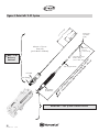
Figure 4. Beta-Cath™ 3.5F System ......................................................................................................................................33
Table 8. Transfer Device Controls and Indicators ...................................................................................................................33
Figure 5. ACTIVE Beta-Cath™ 3.5F System Compatible Transfer Device (60 mm shown) .........................................................35
Procedure Flow .................................................................................................................................................................................36
ACTIVE Device Receipt .............................................................................................................................................................37
A.
B. Radioactive Sealed Source/Device Leak Test Procedure ..................................................................................................................38
C. Therapy Planning .......................................................................................................................................................................39
Figure 6. IST Marker Positions .............................................................................................................................................39
Figure 7. Appropriate Radiation Coverage ...........................................................................................................................39
D. Surveillance of the Cath Lab Room...............................................................................................................................................40
E. Delivery Catheter Inspection/Preparation ......................................................................................................................................40
F.
Placement of the Delivery Catheter ...............................................................................................................................................41
Figure 8. Delivery Catheter Positioning Using the IST .............................................................................................................41
G. IST Removal...............................................................................................................................................................................42
ACTIVE Transfer Device Preparation with the b-Rail™ 3.5F Delivery Catheter .................................................................................42
H.
Figure 9. Sterile Bag..........................................................................................................................................................42
Figure 10. Fluid Management System ..................................................................................................................................43
ACTIVE Transfer Device Preparation with the b-Rail™ 3.5F XL Delivery Catheter .............................................................................43
I.
J.
K.
ACTIVE
Transfer Device Priming ................................................................................................................................................44
ACTIVE Source Train ..........................................................................................................................................44
Source Train Return ......................................................................................................................................................45
Delivery Catheter Removal ..........................................................................................................................................................46
Disassembly of the System...........................................................................................................................................................46
Post Procedural Radiation Checks ................................................................................................................................................46
Drying and Storing of the Transfer Devices....................................................................................................................................47
Emergency Source Recovery Procedure ........................................................................................................................................47
Optional Instructions ...................................................................................................................................................................49
1. IST Reinsertion ......................................................................................................................................................................49
2. In-Vivo Transport of a NON-ACTIVE Source Train.......................................................................................................................50
V. Customer Service Information..............................................................................................................................................................52
VI. Beta-CathTM 3.5 System Specifications ..................................................................................................................................................53
VII. Storage and Transport .......................................................................................................................................................................53
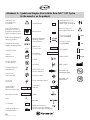
Attachment A: Symbols and Graphics Used with the Beta-Cath™ 3.5F System.................................................................................................54
Attachment B: Additional Dosimetry Information for the Beta-CathTM 3.5F System..............................................................................................55
Estimated Dose to Patient (Non-Target Tissue) and Clinicians in a Typical Procedure..................................................................................55
Dose Verification ...............................................................................................................................................................................56
Dose Distribution ...............................................................................................................................................................................56
Figure 11. Relative Dose Rate from ACTIVE Source Train as a Function of Distance ................................................................57
Attachment C: START amd START 40/20 5-year Follow up ...........................................................................................................................59
L.
M.
N.
O.
P.
Q.
R.
1
Delivery of the
ACTIVE
The Beta-Cath™ System is not indicated for pullback (stepping).
1
D03745 Rev. D
03/08
This page
intentionally
left blank
2
D03745 Rev. D
03/08
I. Introduction
Performed by Medical Physicist, Radiation
Safety Officer or Designee
How To Use This Manual
This manual is intended to guide clinicians that have completed the authorized formal training program for the
Novoste™ Beta-Cath™ 3.5F System. Please contact Best®
Vascular to schedule a training session. Read this manual
completely before system use and keep it readily available for reference. This manual contains recommended
safety procedures as minimum safety guidelines developed from good clinical practices and the “As Low As
Reasonably Achievable” (ALARA) radiation exposure
philosophy.
Definitions:
Indications: Indications are the general descriptions
of the disease or condition the device can be used to
treat, prevent, cure or mitigate including a description
of the patient population for which the device is
intended.
Contraindications: Contraindications are conditions under which the device should NOT be used
because the risk of use outweighs any possible benefit.
Special Considerations: Patient circumstances or
conditions which merit additional attention by the
physician.
Adverse Events: Undesirable effects reasonably
associated with the use of the device. A serious
adverse event refers to an adverse experience that is
life threatening, results in permanent impairment of a
body function, permanent damage to a body structure, necessitates medical/surgical intervention to preclude permanent impairment/damage to a body function/structure.
Performed by Radiation Oncologist,
Medical Physicist, Radiation
Safety Officer or Designee
MP/RSO/D
RO/MP/RSO/D
II. System Description
The Beta-Cath™ 3.5F System is an integrated system
comprised of four components: the b-Rail™ 3.5F Delivery
Catheter, Transfer Device, the Source Train, and the
System Accessories. The System is designed so that the
Transfer Device and the Delivery Catheter are exclusively
compatible.
The b-Rail™ 3.5F Delivery Catheter provides the path
through which the Source Train is delivered to and
retrieved from the site of interventional injury.
Note: This manual is for use with the b-Rail™
3.5F Delivery Catheter and the b-Rail™ 3.5F XL
Delivery Catheter. The b-Rail™ 3.5F Delivery
Catheter may only be used inside the sterile field, using
the Sterile Bag. The b-Rail™ 3.5F XL Delivery Catheter
may be used inside or outside the sterile field.
When the b-Rail™ 3.5F Delivery Catheter is referenced,
it applies to both the b-Rail™ 3.5F Delivery Catheter and
b-Rail™ 3.5F XL Delivery Catheter, unless otherwise specified. Section H is specific to preparing the b-Rail™ 3.5F
Delivery Catheter for use inside the sterile field, and
Section I is specific to using the b-Rail™ 3.5F XL Delivery
Catheter outside the sterile field.
The ergonomically designed Transfer Device stores and
shields the Source Train when not in use, and controls the
hydraulic delivery and return of the Source Train during
the treatment procedure. The gray color-coded
NovosteTM Transfer Device is exclusively compatible with
the b-RailTM 3.5F Delivery Catheter and b-RailTM 3.5F XL
Delivery Catheter.
WARNING: A WARNING statement is used to alert
the user to a potential serious outcome or harm
(death, injury, or serious adverse events) to the user
or to the patient associated with the use or misuses of
the device.
PRECAUTIONS: A precaution statement alerts the
user to exercise special care necessary for the safe
and effective use of the device. Precautions may
include actions to be taken to avoid effects on
patients or users that may not be potentially life
threatening or result in serious injury, but also alert
the user to adverse effects on the device of use or
misuse and the care necessary to avoid such effects.
Note: A note provides additional information to clarify a
point in the text.
Notations In Manual:
Performed by Cardiologist or Designee
Performed by Radiation Oncologist
or Designee
CARD/D
RO/D
3
D03745 Rev. D
03/08
III. Essential Prescribing Information
The Source Train consists of a wire jacketed series of individual, cylindrical, sealed sources containing Sr90/Y90 and
an inactive radiopaque marker at each end. The Source
Train provides the radiation dose during the treatment
procedure.
• Do not over-tighten the hemostatic valve as this may
damage the Delivery Catheter and impede the path
of the ACTIVE Source Train and may cause unintentional exposure of radiation and/or unintended
results.
The System Accessories are the ancillary components of
the Beta-Cath™ 3.5F System that (1) ensure sterility and
facilitate operation of the system during a clinical procedure, (2) permit temporary storage of System components
in the event of a disrupted clinical procedure, (3) facilitate handling of Source Train components if located outside of the System, (4) facilitate Medical Physicist’s operations, and/or (5) enable transport of the System components and Medical Physicist’s Kit.
• Failure to open the hemostatic valve may prevent the
radiation source train from returning to the device
and may result in unnecessary radiation exposure to
the patient or personnel.
Indications
The Beta-Cath™ 3.5F System is intended to deliver beta
radiation to the site of successful Percutaneous Coronary
Intervention (PCI) for the treatment of in-stent restenosis in
native coronary arteries with discrete lesions (treatable
with a 20 mm balloon for the 30 mm and 40 mm
Systems and injury areas up to 40 mm for the 60 mm
System) in a reference vessel diameter ranging from 2.7
mm to 4.0 mm.
Contraindications
• Unprotected left main disease (>50% narrowing).
• Patients in whom antiplatelet and/or anticoagulant
therapy are contraindicated.
Warnings
• Every attempt should be made to avoid restenting of the target lesion to minimize the
risk of thrombosis.
Delivery Catheter & Source Train Placement
• Use of an Internal Mammary (IM) Artery Guide
Catheter may impede the path of the ACTIVE Source
Train and may cause unintentional exposure of radiation and/or unintended results.
• Vessel trauma may result from the improper use of
the Delivery Catheter. Follow the enclosed directions
carefully. When the Delivery Catheter is in the body,
it should be manipulated only under fluoroscopy.
Never advance or withdraw the Delivery Catheter
against resistance without first determining the reason for the resistance under fluoroscopy.
4
D03745 Rev. D
03/08
• Failure to correctly position the Source Train at the
interventional injury site may underexpose the targeted treatment area and expose tissue not targeted for
treatment to unintentional radiation; unpredictable
results may occur. Exceeding the prescribed
radiation treatment time will result in a higher than
intended dose. Migration or improper location of the
Source Train may cause unintentional radiation
exposure to occur and may decrease treatment
efficacy.
• Failure to comply with the specific use of the Transfer
Device controls may result in injury or unintended
radiation exposure. Radiation is emitted from the
Transfer Device when the Radiation Source Train is
in the Source Chamber. To minimize hand dose, the
Transfer Device is designed to be held on the
underside and may also be set down when
appropriate.
Intravascular Radiation Procedure
• If the fluid in the capped Fluid Collection Bag after
the procedure is found to be contaminated after
scanning, then the Transfer Device and capped Fluid
Collection Bag should be placed in the Temporary
Storage Container. Immediately inform Institutional
Radiation Safety personnel, implement contamination
control procedures and call your Best® Vascular
Representative.
• If, at any time, a Survey Meter reading of the
Transfer Device, Delivery Catheter, Fluid Collection
Bag, or Procedure Room is significantly different from
initial baseline readings, stop all activity and re-survey
the Transfer Device, Delivery Catheter, Fluid
Collection Bag, or Procedure Room making sure the
fluoroscopy is off. If the reading is not within the
acceptable baseline range or background range
there may potentially be a misplaced source; refer to
Section Q, Emergency Source Recovery Procedure.
• UNDER NO CIRCUMSTANCES should an individual
attempt to remove the Radiation Source Train from
the Beta-Cath™ 3.5F System, grasp the catheter
directly with hands (when an active Radiation Source
Train is being used), cut the catheter, or pick up a
source with his/her fingers, because unintended radiation exposure and injury may result. Required
equipment is provided for this purpose in the
Response Kit.
III. Essential Prescribing Information
• Should breach of
occur:
ACTIVE
Source Train containment
1. Notify personnel present of missing
source(s).
2. Follow institutional procedures regarding
personnel allowed to enter or leave the
room until the source is contained.
3. Individuals involved in source recovery
should wear disposable gloves, an extremity
dosimeter on the hand expected to receive
the highest dose and a whole body dosimeter on the front of the body between the
neck and the waist.
PRECAUTIONS
• The Beta-Cath™ 3.5F System is designed to be used
by a team of appropriately trained personnel. At a
minimum, this team should include a Cardiologist,
Radiation Oncologist, and Medical Physicist.
Beta-Cath™ 3.5F System Preparation
• Prior to any procedure, the equipment should be
thoroughly examined to verify the proper function
and integrity of the system.
• Handle the Transfer Device carefully and do not use if
dropped. Do not use the Transfer Device if the
controls and indicators are not functioning correctly or
the LED light test is not observed. Do not begin a procedure if the Low Battery light is blinking. If the Low
Battery Indicator starts blinking during a procedure,
there will be enough battery power to complete the
procedure.
• The Transfer Device is not sterile. A Sterile Bag is provided to maintain a sterile field during the procedure.
The inside portion of the tape covering the Syringe Port
Hole and the Proprietary Connector Port Hole of the
sterile bag is not sterile; remove from the sterile field.
• Do not recharge, disassemble, expose to high temperatures or incinerate the provided Transfer Device
battery. Keep in package until ready to use.
Dispose of used battery properly.
• The Transfer Device requires scheduled maintenance
by Best® Vascular within a period not to exceed
twelve months. Refer to each Transfer Device’s
Calibration Certificate for its specified use period.
Please contact your Best® Vascular Representative to
arrange for service.
• Use the Delivery Catheter and Procedure Accessory
Pack before the expiration date noted on the package. Verify that the sterility of the devices has not
been compromised by assuring the package integrity has been maintained. The Delivery Catheter and
Procedure Accessory Pack items are intended for single use. Do not re-sterilize and/or reuse these items.
Do not use if sterile package is damaged.
• Use only Sterile Water for Irrigation, which may
also be referred to as sterile distilled non-pyrogenic
water, in the Transfer Device. Do not use saline as a
hydraulic fluid in the Transfer Device; corrosion may
occur.
• Do not use the Delivery Catheter if there is evidence
of damage. Damaged catheters may cause vessel
trauma or unpredictable results during use.
• Do not use the Delivery Catheter if there is evidence
of fluid leakage other than at the IST hub vent position.
• Use caution when connecting the Proprietary
Connector to the Transfer Device. The Proprietary
Connector of the Delivery Catheter is no longer sterile once disconnected from the Transfer Device.
• Use care when attaching components to the Transfer
Device to ensure that the Sterile Bag does not get
pinched in the process. Ensure a sufficient number
of water-filled syringes are available before beginning treatment. Always reserve at least 10 ml of
water for the return of the ACTIVE Source Train to
prevent unintentional radiation exposure.
• If the self-diagnostic test is not observed, do not use
the device and call your Best® Vascular Representative
for service.
• Do not begin a procedure if the Low Battery light is
blinking. If the Low Battery Indicator starts blinking
during a procedure, there will be enough battery
power to complete the procedure. Should this occur,
replace the battery per instructions found on page 31
of this User’s Manual.
• Do not force the connector lock latch into position. If
resistance is felt, reposition the 3.5F compatible
Flushing Adapter to ensure proper engagement with
the Transfer Device.
• Do not force the connector lock latch into position. If
resistance is felt, reposition the proprietary connector
to ensure proper engagement with the Transfer Device.
5
D03745 Rev. D
03/08
III. Essential Prescribing Information
PRECAUTIONS
Continued
• Ensure that the Gate Control Switch is completely
closed, as incomplete closure may render the Gate
inoperable.
Intravascular Radiation Procedure
• The individual performing the wipe and leak tests for
radioactive material should use good contamination
control techniques.
• If the transferable contamination exceeds 200
dpm/100 cm2 (or the level determined by local
regulation or institutional policy) or the leak test
results exceed 11,100 dpm (or the level determined
by local regulation or institutional policy) on any sample, place the contaminated object(s) in a plastic bag
and label “Caution: Radioactive Material.”
Immediately inform institutional Radiation Safety personnel, implement containment control procedures
and call your Best® Vascular Representative. Should
this occur, do not continue with this procedure.
• Use only the 3.5F compatible Flushing Adapter provided with the Beta-Cath™ 3.5F System. Use of any
other Beta-Cath™ Flushing Adapter will result in an
improper fit and an inability to properly perform the
Leak Test Procedure.
• Always advance the Delivery Catheter with the IST in position within the Delivery Catheter. Never advance or withdraw the Delivery Catheter against resistance. Do not
advance the Delivery Catheter over the floppy portion of
the guidewire as the guidewire may prolapse when the
Delivery Catheter is withdrawn. If this occurs, attempt to
resolve the prolapse by gently pulling back on the
guidewire while simultaneously advancing the catheter. If
the prolapse persists, disengage the Delivery Catheter
from the guidewire by continuing to advance the Delivery
Catheter while gently pulling back on the guidewire.
• Exercise care when withdrawing the Delivery Catheter
through any area of increased restriction, such as
a stent, guide catheter tip, or hemostatic valve. Always
withdraw the Delivery Catheter slowly and observe
under fluoroscopy, whenever possible.
• The Transfer Device contains radioactive material.
Use of this device is restricted to persons licensed
in the handling of radioactive materials. Personnel
handling this device must follow the regulations,
policies and procedures for their institution on the
safety and hazards associated with radioactive
materials.
6
D03745 Rev. D
03/08
• Utilize a manual Blood Pressure Cuff to monitor
patient status during the radiation treatment because
arterial wave form pressure may be dampened while
the Delivery Catheter is in place.
light dur• Illumination of the Red Pressure Indicator
ing a procedure indicates excessive pressure is being
used; reduce applied pressure to return to the
Amber
Pressure Indicator area.
• Do not turn the Transfer Device power On or attempt
to OPEN the Gate Control Switch during the Drying
Procedure.
• Failure to perform adequate visual and radiation surveys post-procedure to verify source accountability may
subject patients and/or personnel to unintended radiation exposure.
Emergency Source Recovery
• Under the undefined handling conditions outside the
System, the ACTIVE Source Train jacket may be damaged, allowing individual ACTIVE Sources to be
released. Use care when locating and handling the
Radioactive Source Train to ensure that all individual
ACTIVE Sources remain intact (jacketed) and are recovered and returned to safe, shielded storage.
• The Response Kit contains two Source Recovery Tools
for picking up and transfering a Source(s) to a safe
location: a) the Source Recovery Probe and b) the
spring-loaded Tweezers. The Source Recovery Probe is
the preferred method as it minimizes potential damage
to the Source(s) and permits the operator’s hand to be
placed further from the Source(s).
• The magnetic Source Recovery Probe should be held
and operated near its release lever in order to avoid
unnecessary radiation exposure.
• In the event a source becomes loose or needs to be
transferred to a safe location, use the source recovery
tools with extreme care in source recovery. Improper
use could damage sources and could potentially
release unsealed radioactive material. Use of the
Source Recovery Probe is the preferred method as it
minimizes potential damage to a source.
III. Essential Prescribing Information
Special Considerations
As with other vascular brachytherapy procedures, safety
and effectiveness has not been demonstrated in the following populations:
• Vessel or lesion morphologies that would preclude
revascularization or placement of the b-Rail™
3.5F Delivery Catheter.
• Patients undergoing or having prior chest radiotherapy.
• Patients presenting with:
- thrombotic lesions;
- multiple vessel lesions;
- vein graft segments;
- overlapping stents;
- myocardial infarction less than or equal to 72
hours prior to the procedure; and/or
- ejection fractions less than 30%.
• Patients unable to tolerate the recommended dwell time
of the Source Train in the Delivery Catheter (3.5 Fr).
• The safety and effectiveness of the Beta-Cath™ 3.5F
System have not been evaluated in reference vessel
diameters < 2.7 mm.
• Patients requiring revascularization methods other than
balloon angioplasty, directional and rotational atherectomy and excimer laser for revascularization of in-stent
restenosis.
• Patients who have received a heart transplant.
• Women of child-bearing potential who are pregnant
or suspect pregnancy.
Adverse Events
The original Beta-Cath™ (5F) System was evaluated in the STents And Radiation Therapy (START) Trial, a multicenter,
randomized, placebo-controlled trial involving 476 patients. The START Trial primarily studied the treatment of lesions treatable with a 20 mm Balloon and a 30 mm Source Train (95%), using the Beta-Cath™ (5F) System. The observed adverse
events are summarized in the following table.
Major Adverse Events – In-Hospital and Out-of-Hospital (to 8 months)
All Patients Treated (N=476)
Sr-90
(N=244 Patients)
Combined (In-and Out-of-Hospital)
Complications to 240 Days
Any MACE (Death, MI, Emergent CABG, TVR)
Death
Myocardial Infarction (Q or Non-Q)
Q Wave MI
Non-Q Wave MI
Emergent CABG
Target Lesion Revascularization
TL-CABG
TL-PTCA
Target Vessel Revascularization not involving the TL*
TV-CABG
TV-PTCA
Target Vessel Revascularization
TV-CABG
TV-PTCA
Stent Thrombosis (to 30 days)
Site Thrombosis (Days 31-240)
Abrupt Closure
Subacute Closure
Bleeding Complications
Vascular Complications
CVA
Number
44
3
4
%
18.0%
1.2%
1.6%
Placebo
(N=232 Patients)
Number
60
1
7
%
25.9%
0.4%
3.0%
All Randomized
(N=476 Patients)
Number
104
4
11
%
21.8%
0.8%
2.3%
0
4
1
0.0%
1.6%
0.4%
0
7
0
0.0%
3.0%
0.0%
0
11
1
0.0%
2.3%
0.2%
32
20
12
13.1%
8.2%
4.9%
52
24
30
22.4%
10.3%
12.9%
84
44
42
17.6%
9.2%
8.8%
11
2
9
4.5%
0.8%
3.7%
15
2
13
6.5%
0.9%
5.6%
26
4
22
5.5%
0.8%
4.6%
39
21
19
16.0%
8.6%
7.8%
56
24
34
24.1%
10.3%
14.7%
95
45
53
20.0%
9.5%
11.1%
0
0
0
0.0%
0.0%
0.0%
1
0
1
0.4%
0.0%
0.4%
1
0
1
0.2%
0.0%
0.2%
0
4
4
0.0%
1.6%
1.6%
1
4
3
0.4%
1.7%
1.3%
1
8
7
0.2%
1.7%
1.5%
1
0.4%
1
0.4%
2
0.4%
*Target vessel revascularization not involving the target lesion was defined as target vessel revascularization at a site other than the target site with or without concomitant target lesion revascularization
7
D03745 Rev. D
03/08
III. Essential Prescribing Information
Adverse Events
Continued
Three (3) patients who received radiation died during the
START trial. The deaths occurred between 167 and 225
days. One (1) patient died due to coronary artery disease, congestive heart failure, and multi-system dysfunction. It could not be determined if the cause of death was
device-related. The cause of death for the other two
patients was determined not to be device-related.
There were 476 patients treated with the Beta-Cath™
(5F) System (BCS) in the Stents and Radiation Therapy
(START) Trial. Device success, defined as successful delivery and treatment with the BCS, was achieved in 467 of
the 476 patients (~98%). The table provided below outlines the details of the malfunctions reported as part of
the treatment of the 476 patients. The 108 patient treatments with device malfunctions include 89 cases with
minor device malfunctions, 10 cases with initial device
malfunctions with subsequent treatment success, and 9
device failures preventing treatment success.
Summary of Device Malfunctions
# of Patients
Number of patients enrolled in START Trial . . .476
Number of Cases with Device Malfunctions . . .108
Number of Cases with unsuccessful
delivery and treatment with the BCS . . . . . .9
Number of cases reporting initial
device malfunctions with subsequent
treatment success . . . . . . . . . . . . . . . . . . .l0
Number of minor malfunctions not
affecting Ability to Treat . . . . . . . . . . . . . .89
Number of Cases Resulting In Use of
the Temporary Storage Container*
(included in the Device Malfunctions
category listed above) . . . . . . . . . . . . . . . . . . .6
Patients Unsuccessfully Treated and
Involving Use of the Temporary Storage
Container* . . . . . . . . . . . . . . . . . . . . . . . .1
*(Bail-Out is defined as physician use of the Novoste™ Temporary Storage Container)
8
D03745 Rev. D
03/08
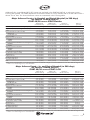
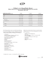
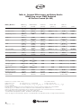
Additionally, the original Beta-Cath™ (5F) System was evaluated in the START 40/20 Trial, a multi-center registry
involving 207 patients. The START 40/20 Trial studied the treatment of lesions treatable with a 20 mm balloon with a
40 mm Source Train. The observed adverse events are summarized in the following tables.
Major Adverse Events – In-Hospital and Out-of-Hospital (to 240 days)
All Patients Treated (N=439)
START 40/20 versus START Placebo
START 40/20
(N=207 Patients)
START Placebo
(N=232 Patients)
All Patients
(N=439 Patients)
Difference
[95% C.I]
Combined (In-and Out-of-Hospital) Complications to 240 Days
Any MACE (Death, MI, Emergent CABG, TVR)
19.3% (40/207)
Death
2.4% (5/207)
Myocardial Infarction (Q or Non-Q)
4.3% (9/207)
Q Wave MI
1.4% (3/207)
Non-Q Wave MI
2.9% (6/207)
Emergent CABG
0.0% (0/207)
Target Lesion Revascularization
11.1% (23/207)
TL-CABG
6.8% (14/207)
TL-PTCA
5.3% (11/207)
Target Vessel Revascularization not involving the TL*
8.2% (17/207)
TV-CABG
1.4% (3/207)
TV-PTCA
6.8% (14/207)
Target Vessel Revascularization
15.9% (33/207)
TV-CABG
7.7% (16/207)
TV-PTCA
9.2% (19/207)
Stent Thrombosis (to 30 days)
0.0% (0/207)
Site Thrombosis (Days 31-240)
1.0% (2/207)
Abrupt Closure
0.0% (0/207)
Subacute Closure
0.0% (0/207)
Bleeding Complications
3.4% (7/207)
Vascular Complications
1.0% (2/207)
CVA
1.0% (2/207)
*Target vessel revascularization not involving the target lesion was defined as
or without concomitant target lesion revascularization.
25.9% (60/232)
22.8% (100/439)
-6.5% [-14.3%, 1.3%]
0.4% (1/232)
1.4% (6/439)
2.0% [-0.3%, 4.2%]
3.0% (7/232)
3.6% (16/439)
1.3% [-2.2%, 4.9%]
0.0% (0/232)
0.7% (3/439)
1.4% [-0.2%, 3.1%]
3.0% (7/232)
3.0% (13/439)
-0.1% [-3.3%, 3.1%]
0.0% (0/232)
0.0 (0/439)
0.0% [-,-]
22.4% (52/232)
17.1% (75/439)
-11.3% [-18.2%, -4.4%]
10.3% (24/232)
8.7% (38/439)
-3.6% [-8.8%, 1.6%]
12.9% (30/232)
9.3% (41/439)
-7.6% [-12.9%, -2.3%]
6.5% (15/232)
7.3% (32/439)
1.7% [-3.2%, 6.6%]
0.9% (2/232)
1.1% (5/439)
0.6% [-1.4%, 2.6%]
5.6% (13/232)
6.2% (27/439)
1.2% [-3.4%, 5.7%]
24.1% (56/232)
20.3% (89/439)
-8.2% [-15.6%, -0.8%]
10.3% (24/232)
9.1% (40/439)
-2.6% [-8.0%, 2.7%]
14.7% (34/232)
12.1% (53/439)
-5.5% [-11.5%, 0.5%]
0.4% (1/232)
0.2% (1/439)
-0.4% [-1.3%, 0.4%]
0.0% (0/232)
0.5% (2/439)
1.0% [-0.4%, 2.3%]
0.4% (1/232)
0.2% (1/439)
-0.4 [-1.3%, 0.4%]
0.4% (1/232)
0.2% (1/439)
-0.4% [-1.3%, 0.4%]
1.7% (4/232)
2.5% (11/439)
1.7% [-1.3%, 4.6%]
1.3% (3/232)
1.1% (5/439)
-0.3% [-2.3%, 1.6%]
0.4% (1/232)
0.7% (3/439)
0.5% [-1.0%, 2.1%]
target vessel revascularization at a site other than the target site with
Major Adverse Events – In- and Out-of-Hospital (to 240 days)
All Patients Treated (N=451)
START 40/20 versus START Sr-90
START 40/20
(N=207 Patients)
START Sr-90
(N=244 Patients)
All Patients
(N=451 Patients)
Difference
[95% C.I]
18.0% (44/244)
1.2% (3/244)
1.6% (4/244)
0.0% (0/244)
1.6% (4/244)
0.4% (1/244)
13.1% (32/244)
8.2% (20/244)
4.9% (12/244)
4.5% (11/244)
0.8% (2/244)
3.7%(9/244)
16.0% (39/244)
8.6% (21/244)
7.8% (19/244)
0.0% (0/244)
0.0% (0/244)
0.0% (0/244)
0.0% (0/244)
1.6% (4/244)
1.6% (4/244)
0.4% (1/244)
18.6% (84/451)
1.8% (8/451)
2.9% (13/451)
0.7% (3/451)
2.2% (10/451)
0.2% (1/451)
12.2% (55/451)
7.5% (34/451)
5.1% (23/451)
6.2% (28/451)
1.1% (5/451)
5.1% (23/451)
16.0% (72/451)
8.2% (37/451)
8.4% (38/451)
0.0% (0/451)
0.4% (2/451)
0.0% (0/451)
0.0% (0/451)
2.4% (11/451)
1.3% (6/451)
0.7% (3/451)
1.3% [-5.9%, 8.5%]
1.2% [-1.3%, 3.7%]
2.7% [-0.5%, 5.9%]
1.4% [-0.2%, 3.1%]
1.3% [-1.5%, 4.0%]
-0.4% [-1.2%, 0.4%]
-2.0% [-8.0%, 4.0%]
-1.4% [-6.3%, 3.4%]
0.4% [-3.7%, 4.5%]
3.7% [-0.9%, 8.3%]
0.6% [-1.4%, 2.6%]
3.1% [-1.1%, 7.2%]
-0.0% [-6.8%, 6.7%]
-0.9%[-5.9%, 4.2%]
1.4% [-3.8%, 6.6%]
0.0%[-,-]
1.0% [-0.4%, 2.3%]
0.0% [-,-]
0.0% [-,-]
1.7% [-1.2%, 4.7%]
-0.7% [-2.8%, 1.4%]
0.6% [-1.0%, 2.1%]
Combined (In-and Out-of-Hospital) Complications to 240 Days
Any MACE (Death, MI, Emergent CABG, TVR)
Death
Myocardial Infarction (Q or Non-Q)
Q Wave MI
Non-Q Wave MI
Emergent CABG
Target Lesion Revascularization
TL-CABG
TL-PTCA
Target Vessel Revascularization not involving the TL*
TV-CABG
TV-PTCA
Target Vessel Revascularization
TV-CABG
TV-PTCA
Stent Thrombosis (to 30 days)
Site Thrombosis (Days 31-240)
Abrupt Closure
Subacute Closure
Bleeding Complications
Vascular Complications
CVA
19.3% (40/207)
2.4% (5/207)
4.3% (9/207)
1.4% (3/207)
2.9% (6/207)
0.0% (0/207)
11.1% (23/207)
6.8% (14/207)
5.3% (11/207)
8.2% (17/207)
1.4% (3/207)
6.8% (14/207)
15.9% (33/207)
7.7% (16/207)
9.2% (19/207)
0.0% (0/207)
1.0% (2/207)
0.0% (0/207)
0.0% (0/207)
3.4% (7/207)
1.0% (2/207)
1.0% (2/207)
*Target vessel revascularization not involving the target lesion was defined as target vessel revascularization at a site other than the target site with
or without concomitant target lesion revascularization.
9
D03745 Rev. D
03/08
Five (5) patients who received radiation died during the
START 40/20 trial. The deaths occurred between 17
and 200 days. Two (2) patients died of cardiac deaths
related to the target lesion: one following non-QMI/heart
failure complicating the index procedure and one of massive GI bleed/ischemic bowel complicating reintervention with Reopro (Eli Lilly and Company) of the target
lesion. The remaining three died of cardiac death not
related to the target lesions or the device: one patient
died from CHF and multi-system failure following a nontarget lesion intervention; one patient died from complications surrounding an intracerebral bleed; and one
patient died following aortic valve replacement and nontarget vessel CABG.
®
There were 207 patients treated with the Beta-Cath™
(5F) System (BCS) in the Stents and Radiation Therapy
40/20 Trial. Device success, defined as successful delivery and treatment with the BCS, was achieved in 200 of
the 207 patients (~97)%.
Summary of Device Malfunctions
# of Patients
Number of patients enrolled in START 40/20 Trial .207
Number of Cases with unsuccessful
delivery and treatment with the BCS . . . . . . . . .7
Number of cases reporting initial device
malfunctions with subsequent treatment success...3
Number of Cases Resulting In Use of the
Temporary Storage Container* (included in
the Device Malfunctions category listed above)....8
Patients Unsuccessfully Treated and Involving
Use of the Temporary Storage Container* . . . . .1
*(Bail-Out is defined as physician use of the Novoste™ Temporary Storage Container)
10
D03745 Rev. D
03/08
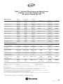
The original Beta-Cath™ (5F) System was evaluated in a
subset analysis of the European Surveillance REgistry
with the NOvoste Beta-Cath™ System (RENO)
Registry), a prospective commercial registry at 46 centers in Europe involving 1098 patients. This subset analysis included a comparison of 139 patients from the
RENO registry (RENO-Long Subgroup) that had diffuse
in-stent restenotic lesions in single vessels treated by
longer than 40 mm of radiation source train as compared to a placebo control group (94 patients) obtained
from the WRIST and LONG WRIST studies by selecting
the cases which required longer or equal to 13 seeds of
dummy sources and to the START trial results.
Additionally, comparisons were made between the pullback1 and 60mm source train groups of the RENO-Long
Subgroup to ensure the outcomes could be pooled.
Treatments with the Beta-Cath™ (5F) System included
stepping (pullback) procedures utilizing either 30, 40 or
60 mm source trains or a single 60 mm source train. The
observed adverse events are summarized in the following
tables:
RENO-Long versus WRIST/Long-WRIST Control
Major Adverse Events - In-and Out-of-Hospital (to 6 months)
All Patients (N=233)
Combined In- and OutOf-Hospital Events to 6-Months
RENO-Long
(N=139)
WRIST/LongWRIST Control (N=94)
Combined
(N=233)
MACE
17.9% (24/134)
64.9% (61/94)
37.3% (85/228)
Death
2.2% (3/134)
2.1% (2/94)
2.2% (5/228)
MI (Q or Non-Q)
1.5% (2/134)
17.0% (16/94)
7.9% (18/228)
Q-wave MI
0.7% (1/134)
1.1% (1/94)
0.9% (2/228)
Non Q-wave MI
0.7% (1/134)
16.0% (15/94)
7.0% (16/228)
14.9% (20/134)
60.6% (57/94)
33.8% (77/228)
TV-PTCA
2.2% (3/134)
9.6% (9/94)
5.3% (12/228)
TV-CABG
12.7% (17/134)
56.4% (53/94)
30.7% (70/228)
TVR
1
The Beta-Cath™ System is not indicated for pullback (stepping).
11
D03745 Rev. D
03/08
RENO-Long versus START Placebo
Major Adverse Events - In-and Out-of-Hospital
All Patients (N=371)
Combined In- and OutOf-Hospital Events
RENO-Long
(N=139)
START Placebo
(N=232)
Combined
(N=371)
MACE
17.9% (24/134)
25.9% (60/232)
23.0% (84/366)
Death
2.2% (3/134)
0.4% (1/232)
1.1% (4/366)
MI
1.5% (2/134)
3.0% (7/232)
2.5% (9/366)
Q-wave MI
0.7% (1/134)
0.0% (0/232)
0.3% (1/366)
Non Q-wave MI
0.7% (1/134)
3.0% (7/232)
2.2% (8/366)
14.9% (20/134)
24.1% (56/232)
20.8%(76/366)
TV-PTCA
12.7% (17/134)
14.7% (34/232)
13.9% (51/366)
TV-CABG
2.2% (3/134)
10.3% (24/232)
7.4% (27/366)
TVR
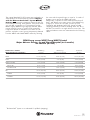
RENO-Long versus START Radiation
Major Adverse Events - In- and Out-of-Hospital
All Patients (N=383)
Combined In- and OutOf-Hospital Events
RENO-Long
(N=139)
START Radiation(N=244)
Combined
(N=383)
MACE
17.9% (24/134)
18.0% (44/244)
18.0% (68/378)
Death
2.2% (3/134)
1.2% (3/244)
1.6% (6/378)
MI
1.5% (2/134)
1.6% (4/244)
1.6% (6/378)
Q-wave MI
0.7% (1/134)
0.0% (0/244)
0.3% (1/378)
Non Q-wave MI
0.7% (1/134)
1.6% (4/244)
1.3% (5/378)
14.9% (20/134)
16.0% (39/244)
15.6% (59/378)
TV-PTCA
12.7% (17/134)
7.8% (19/244)
9.5% (36/378)
TV-CABG
2.2% (3/134)
8.6% (21/244)
6.3% (24.378)
TVR
12
D03745 Rev. D
03/08
Pullback1 versus Non-pullback (60 mm)
Major Adverse Events - In- and Out-of-Hospital (to 6 months)
All Patients (N=139)
Combined In- and OutOf-Hospital Events to 6 Months
Pullback
(N=109)
Non-pullback
(N=30)
Combined
(N=139)
MACE
19.0% (20/105)
13.8% (4/29)
17.9% (24/134)
Death
2.9% (3/105)
0.0% (0/29)
2.2% (3/134)
MI
0.0% (0/105)
6.9% (2/29)
1.5% (2/134)
Q-wave MI
0.0% (0/105)
3.4% (1/29)
0.7% (1/134)
Non Q-wave MI
0.0% (0/105)
3.4% (1/29)
0.7% (1/134)
16.2% (17/105)
10.3% (3/29)
14.9% (20/134)
TV-PTCA
13.3% (14/105)
10.3% (3/29)
12.7% (17/134)
TV-CABG
2.9% (3/105)
0.0% (0/29)
2.2% (3/134)
TVR
The following adverse events were NOT observed during
the clinical investigations, but are recognized as potential
adverse events associated with the non-radioactive portion
of vascular brachytherapy, including (but not limited to):
•
•
•
•
•
•
•
•
•
•
•
•
•
•
•
•
•
•
•
•
•
1
Additional potential Adverse Events associated with the
radiation portion of vascular brachytherapy include (but
are not limited to):
Arrhythmia
Arterial Damage, Dissection or Perforation
Vascular Access Site Hematoma
Contrast-Induced Nephrotoxicity
Neurologic Complications
Allergic Reactions
Infection
Stroke
Thrombotic Occlusion
Renal Insufficiency
Coronary Artery Bypass Graft Surgery
Slow Flow-Phenomenon
AV Fistula
Pseudoaneurysm
Left Ventricular Dysfunction
Systemic Atheroembolization
Endocarditis
Distal Embolizations
Vasospasm
Arterial Perforation
Retroperitoneal Hematoma
•
•
•
•
•
•
•
•
•
Radiation-Induced Malignancy
Aneurysm
Excessive Radiation Exposure to Patient/Staff
Arterial Damage
Coronary Artery Bypass Graft Surgery
Thrombosis
Restenosis
Myocardial Infarction
Death
The Beta-Cath™ System is not indicated for pullback (stepping).
13
D03745 Rev. D
03/08
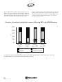
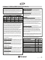
Antiplatelet Therapy
To minimize the risk of thrombosis when new stents are
implanted in conjunction with radiation therapy, a minimum of three (3) months antiplatelet therapy is recommended with the 30 and 40 mm Beta-Cath™ 3.5F
System, and a minimum of six (6) months with the 60 mm
Beta-Cath™ 3.5F System. If a new stent is not implanted
in conjunction with radiation therapy, antiplatelet therapy
should be administered at the physician’s discretion.
Novoste START Trial
The START (STents And Radiation Therapy) Trial, a
multicenter, randomized, placebo-controlled trial, began
in September 1998. The START Trial primarily studied the
treatment of lesions treatable with a 20 mm Balloon with
a 30 mm Source Train (95%), using the Beta-Cath™ (5F)
System. The acute and 8-month clinical and angiographic results showed that the procedure success rate, defined
as the attainment of a residual stenosis of <50%, without
in-hospital major adverse cardiac events (MACE [death,
Q wave and non-Q wave MI, emergent CABG, and target vessel revascularization]), was 97.1% (237/244) in
the Sr-90 arm and 97.0% (225/232) in the Placebo arm
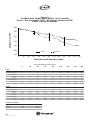
(p=0.9237). The Kaplan-Meier estimate of freedom from
MACE at 8 months was 81.4% in the Sr-90 arm and
72.2% in the Placebo arm (p=0.0393). The KaplanMeier estimate of freedom from target vessel failure (TVF),
defined as target vessel revascularization, MI, or death,
at 8 months was 81.4% in the Sr-90 arm and 72.2% in
the Placebo arm (p=0.0393).
A total of 476 patients were enrolled at 50 US,
Canadian, and European investigational sites in the
placebo-controlled, triple-masked, multicenter START Trial.
All 476 of the enrolled patients were randomized to
receive either the active Beta-Cath™ (5F) System (n=244)
or placebo Beta-Cath™ (5F) System (n=232). The primary
endpoint of 8-month clinical target vessel failure was
defined as the composite of death, myocardial infarction
(Q-wave and non-Q-wave), coronary artery bypass graft
surgery (CABG), and revascularizations attributed to the
target vessel (TVR). A clinical events committee, masked
to the treatment assignment, adjudicated all major endpoints. Eligible patients, with angina or a positive functional study, were identified for elective treatment of instent restenosis in a native coronary artery lesion visually
estimated to be between 2.7 and 4.0 mm in diameter
and treatable with up to a 20 mm (length) angioplasty
balloon. These patients underwent successful percutaneous coronary interventions (defined as revascularization by balloon angioplasty, directional and rotational
atherectomy, and excimer laser) after which treatment
with the randomized Beta-Cath™ (5F) System (active or
14
D03745 Rev. D
03/08
placebo) was administered. After the vascular brachytherapy treatment, additional percutaneous coronary interventional techniques or devices were utilized as deemed
necessary by the clinician. Placement of a new stent,
while discouraged, occurred at the discretion of the clinician in 21% (n=101) of the cases.
Radiation was prescribed according to the following reference vessel diameter: > 2.7 < 3.35 mm received 18.4
Gy* and > 3.35 < 4.0 mm received 23 Gy* at a distance 2mm from the centerline of the source train.
*18.4 and 23 Gray reflect the NIST-recommended adjustments to the documented doses as
described in Technical Report DSGN-0311-A and are equivalent to the 16 and 20 Gray documented doses described in the START Trial.
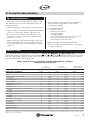
The Antiplatelet/Anticoagulant regimen administered for
the 476 patients in the START Trial were as follows:
Antiplatelet/
Anticoagulant1
Ticlopidine
D u r a t i o n
( D a y s )
0-14
15-30
31-60
61-90
>90
Unconfirmed
9
50
3
0
0
3
23
121
42
55
12
10
0
0
0
1**
1***
1****
(250-500mg/day)
Clopidogrel
(75mg/day)
Ticlopidine/Clopidogrel
1
145 patients received no additional antiplatelet therapy other than aspirin.
**One patient received Ticlopidine for 30 days followed by Clopidogrel for 60 days.
***One patient received Ticlopidine for 14 days followed by Clopidogrel for 155 days.
****One patient received Ticlopidine for 7 days followed by Clopidogrel for an unconfirmed duration.
Clinical follow-up occurred at in-hospital, 1 month, and 8
months. Angiographic follow-up occurred at 8 months.
The study randomization was successful as both treatment
groups were found to be demographically equivalent. All
randomized patients were included in the intent-to-treat
analysis. The principal effectiveness and safety results are
presented in Table 1 followed by the freedom from target
vessel failure Kaplan-Meier curve, Figure 1. The mean
lesion length studied was 16.1mm with approximately
30% of the lesions greater than 19 mm.
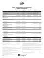
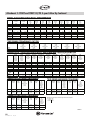
Table 1. Principal Effectiveness and Safety Results - START Trial
All Patients Treated (N=476)
Efficacy Measures
8 Month Stent Segment Binary Restenosis Rate
8 Month Analysis Segment Binary Restenosis Rate
TLR-Free at 240 Days*
TVR-Free at 240 Days*
TVF-Free at 240 Days*
MACE-Free at 240 Days*
Target Lesion Success
Procedure Success
Device Success
Post-Procedure Stent Segment Minimal
Lumen Diameter (MLD, in mm)
Mean± SD (N)
Range (min, max)
Post-Procedure Analysis Segment Minimal
Lumen Diameter (MLD, in mm)
Mean± SD (N)
Range (min, max)
Post-Procedure Stent Segment Percent
Diameter Stenosis (% DS)
Mean± SD (N)
Range (min, max)
Post-Procedure Analysis Segment Percent
Diameter Stenosis (% DS)
Mean± SD (N)
Range (min, max)
Follow-Up Stent Segment Minimal Lumen
Diameter (MLD, in mm)
Mean± SD (N)
Range (min, max)
Follow-Up Analysis Segment Minimal
Lumen Diameter (MLD, in mm)
Mean± SD (N)
Range (min, max)
Follow-Up Stent Segment Percent
Diameter Stenosis (% DS)
Mean± SD (N)
Range (min, max)
Follow-Up Analysis Segment Percent
Diameter Stenosis (% DS)
Mean± SD (N)
Range (min, max)
Sr-90
(N=244 Patients)
Placebo
(N-232 Patients)
Relative Risk
[95% C.I.]
Difference
[95% C.I.]
P-value
14.2% (28/197)
28.8% (57/198)
86.4%
83.5%
81.4%
81.4%
99.6% (243/244)
97.1% (237/244)
98.4% (240/244)
41.2% (77/187)
45.2% (85/188)
75.6%
73.8%
72.2%
72.2%
99.1% (230/232)
97.0% (225/232)
97.8% (227/232)
0.3 [0.24, 0.51]
0.6 [0.49, 0.83]
1.14 [1.03, 1.27]
1.13 [1.01, 1.27]
1.13 [1.00, 1.27]
1.13 [1.00, 1.27]
1.0 [0.99, 1.02]
1.0 [0.97, 1.03]
1.0 [0.98, 1.03]
-27.0% [-35.5%, -18.4%]
-16.4% [-25.9%, -6.9%]
10.8% [2.5%, 19.0%]
9.7% [1.1%, 18.3%]
9.2% [0.3%, 18.1%]
9.2% [0.3%, 18.1%]
0.5%[-1.0%, 1.9%]
0.1% [-2.9%, 3.2%]
0.5% [-1.9%, 3.0%]
0.0000
0.0008
0.0090
0.0283
0.0393
0.0393
0.5332
0.9237
0.6796
2.17±0.42 (242)
(1.12, 3.47)
2.15±0.42 (229)
(1.20, 3.40)
0.02 [-0.06, 0.09]
0.6503
1.94±0.39 (243)
(1.03, 3.02)
1.94±0.41 (230)
(0.98, 3.10)
-0.00 [-0.08, 0.07]
0.9058
22.9%±13.5% (242)
(-31.1%, 53.2%)
22.9%±12.9% (229)
(-19.6%, 51.9%)
0.0% [-2.4, 2.4%]
0.9972
31.4%±10.2% (243)
(6.7%, 57.6%)
30.7%±11.0% (230)
(5.8%, 62.5%)
0.7% [-1.2, 2.6%]
0.4800
1.96±0.66 (197)
(0.00, 3.45)
1.47±0.60 (187)
(0.00, 2.65)
0.49 [0.36, 0.62]
0.0000
1.65±0.64 (198)
(0.00, 3.18)
1.41±0.58 (188)
(0.00, 2.66)
0.24 [0.12, 0.36]
0.0001
30.4%±22.7% (197)
(-32.2%, 100.0%)
47.9%±20.8% (187)
(-4.4%, 100.0%)
-17.5% [-21.9, -13.1%]
0.0000
41.7%±20.7% (198)
(-10.4%, 100.0%)
50.1±19.7% (188)
(13.4%, 100.0%)
-8.5% [-12.5, -4.4%]
0.0000
0.3% [-2.4%, 3.0%]
-8.2% [-15.3%, -1.0%]
-7.8% [-15.2%, -0.4%]
0.5% [-0.5%, 1.5%]
-0.4% [-1.3%, 0.4%]
0.0% [-,-]
0.3% [-3.5%, 4.2%]
0.8255
0.0261
0.0388
0.3292
0.3046
0.8720
Safety Measures and Other Clinical Events to 240 days
In-Hospital MACE
Out-of-Hospital MACE to 240 Days
In- and Out-of-Hospital MACE to 240 Days
Aneurysm†
Stent Thrombosis (to 30 days)
Site Thrombosis (Days 31-240)
Total Occlusions (Angiographic)
Numbers are % (counts/sample size) or Mean ± SD.
N/A = Not applicable.
Relative Risk = Sr-90/Placebo SE = sqrt{(1-p1)/n11+(1-p2)/n21}
SE = sqrt(p1*q1/n1+p2*q2/n2)
Difference = Sr-90 – Placebo
2.5%
16.0%
18.0%
0.5%
0.0%
0.0%
4.0%
(6/244)
(39/244)
(44/244)
(1/198)
(0/244)
(0/244)
(8/198)
CI = Confidence Interval
CI = RR*exp(±1.96*SE)
CI = Diff±1.96*SE
Target Lesion Success = Attainment of a final residual stenosis of <50% (by QCA) using any percutaneous
method. If QCA was not available, the visual estimate of diameter stenosis was used.
Procedure Success = Attainment of a final residual stenosis of <50% (by QCA) using any percutaneous method
and no in-hospital major adverse cardiac events (MACE). If QCA was not available, the visual estimate of
diameter stenosis was used.
Device Success = Successful delivery of the Beta-Cath™ System.
Stent segment was defined as the area confined to the proximal and distal borders of the stent.
Analysis segment was defined as the segment that extends 5 mm proximal and distal to the radiated or injured
landmark, whichever was longest in length.
*Survival estimates from Kaplan-Meier method. Standard error estimate from Peto formula.
TLR-free = Freedom from target lesion revascularization.
TVR-free = Freedom from target vessel revascularization.
TVF-free = Freedom from death, MI, and target vessel revascularization.
MACE-free = Freedom from death, MI, emergent CABG, and target vessel revascularization.
In-Hospital MACE = Death, Q wave or non-Q wave MI, emergent CABG, or target vessel revascularization prior
to discharge as determined by the independent Clinical Events Committee.
2.2%
24.1%
25.9%
0.0%
0.4%
0.0%
3.7%
(5/232)
(56/232)
(60/232)
(0/188)
(1/232)
(0/232)
(7/188)
1.1[0.35, 3.69]
0.7 [0.46, 0.96]
0.7 [0.49, 0.98]
-[-,-]
0.0 [-,-]
-[-,-]
1.1 [0.40, 2.93]
Out-of-Hospital MACE = Death, Q wave or non-Q wave MI, emergent CABG, or target vessel revascularization
from hospital discharge through the 240-day contact, as determined by the independent Clinical Events
Committee.
Stent thrombosis was defined as angiographic thrombus or subacute closure within the target vessel at the time of
the clinically driven angiographic restudy for documented ischemia (chest pain and ECG changes). Any
death not attributed to a non-cardiac cause within the first 30 days was considered a surrogate for thrombosis in the absence of documented angiographic stent patency.
Site thrombosis was defined as myocardial infarction attributable to the target vessel with angiographic documentation (site-reported or by QCA) of thrombus or total occlusion at the target site >30 days after the index procedure in the absence of an intervening revascularization of the target vessel.
Aneurysm was defined as an expansion of the lumen by at least 20% compared with the normal lumen dimensions in the treatment region (analyzed segment) that extends with a wide or narrow mouth beyond the
apparent normal contour.
†Baseline QCA for patient 15/3 revealed the presence of an aneurysm. The Angiographic Core Laboratory
reported the absolute size of the aneurysm changed very little from baseline to follow-up and that the larger
appearance at follow-up was due to the smaller reference vessel dimension rather than an increase in
aneurysm size.
Total Occlusion = An MLD of zero at follow-up as assessed by QCA.
15
D03745 Rev. D
03/08
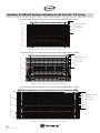
Figure 1:
Freedom from Target Vessel Failure (at 12 months)
Event – free Survival + 1.5SE; All Lesions Treated (n=476)
START Trial versus Placebo
100%
Freedom from TVF
90%
80%
70%
60%
50%
Placebo
Sr-90
40%
0
30
60
90
120
150
180
210
240
270
300
330
360
Time after initial procedure (days)
Time after initial procedure (days)
0
30
60
90
180
210
240
270
360
244
1
241
1
231
4
222
0
217
1
201
0
195
12
179
19
151
145
0
243.5
2
0
240.5
9
0
229.0
5
0
222.0
5
9
5
5
0
216.5
15
5
0
201.0
6
6
0
189.0
4
4
0
169.5
9
3
0
78.5
5
2
99.2%
0.6%
95.5%
1.4%
93.4%
1.6%
91.2%
1.9%
84.9%
2.3%
82.4%
2.5%
80.7%
2.7%
76.2%
3.0%
73.6%
37.8%
232
0
0
230
5
0
219
1
0
213
1
0
203
0
0
176
0
0
172
4
0
160
14
0
134
122
0
232.0
2
227.5
6
218.5
5
6
5
212.5
9
9
203.0
27
9
176.0
4
4
170.0
8
8
153.0
12
4
73.0
12
4
99.1%
0.6%
96.5%
1.3%
94.3%
1.6%
90.3%
2.0%
78.3%
2.8%
76.5%
2.9%
72.9%
3.0%
67.1%
3.3%
60.9%
38.1%
Deg Frdm
1
1
P-Value
0.0139
0.0086
Sr-90
# Entered
# Lost to Follow-up
# Incomplete
# At risk
# Events
# Events/Month
% Survived
% SE
Placebo
# Entered
# Lost to Follow-up
# Incomplete
# At risk
# Events
# Events/Month
% Survived
% SE
Test Between Groups
Test
Chi-Square
6.05
Wilcoxon
6.90
Log-Rank
16
D03745 Rev. D
03/08
The START 40/20 Trial
The START 40/20 (STents And Radiation Therapy) Trial,
a multicenter, prospective registry trial, began in June
1999. The START 40/20 Trial studied the treatment of
lesions treatable with a 20 mm balloon with a 40 mm
Source Train, using the Beta-Cath™ (5F) System. The
acute and 8-month clinical and angiographic results
showed that the procedure success rate, defined as the
attainment of a residual stenosis of <50%, without in-hospital major adverse cardiac events (MACE [death, Qwave and non-Q-wave MI, emergent CABG, and target
vessel revascularization]), was 93.7% (194/207). The
Kaplan-Meier estimate of freedom from MACE at 8
months was 80.0%. The Kaplan-Meier estimate of freedom from target vessel failure (TVF), defined as target
vessel revascularization, MI, or death, at 8 months was
80.0%. A total of 207 patients were enrolled at 22 US
and European investigational sites in the START 40/20
Trial. All 207 of the enrolled patients received the active
40 mm Beta-Cath™ (5F) System. The primary end-point
of 8-month clinical target vessel failure was defined as
the composite of death, myocardial infarction (Q-wave
and non-Q-wave), coronary artery bypass graft surgery
(CABG), and revascularizations attributed to the target
vessel (TVR). A clinical events committee adjudicated all
major endpoints. Eligible patients, with angina or positive functional study, were identified for elective treatment
of in-stent restenosis in a native coronary artery lesion
visually estimated to be between 2.7 and 4.0 mm in
diameter and treatable with up to a 20 mm (length)
angioplasty balloon. These patients underwent successful percutaneous coronary interventions (defined as
revascularization by balloon angioplasty, directional and
rotational atherectomy, and excimer laser) after which
treatment with the 40 mm Beta-Cath™ (5F) System was
administered. After the vascular brachytherapy treatment, additional percutaneous coronary interventional
techniques or devices were utilized as deemed necessary
by the clinician. Placement of a new stent, while discouraged, occurred at the discretion of the clinician in
15.3% (n=31/207) of the cases. Radiation was prescribed according to the following reference vessel diameter: > 2.7 < 3.35 mm received 18.4 Gy* and > 3.35
< 4.0 mm received 23 Gy* at a distance 2 mm from the
centerline of the source train.
The Antiplatelet/Anticoagulant regimen administered for the
207 patients in the START 40/20 Trial were as follows:
Antiplatelet/
Anticoagulant1,2,3,4
Ticlopidine
D u r a t i o n
≤30 days
( D a y s )
31-60
61-90
>90
Unconfirmed
4
0
0
2
0
38
2
72
37
10
0
1*
0
2**
0
(250-500mg/day)
Clopidogrel
(75mg/day)
Ticlopidine/Clopidogrel
11 patients received no antiplatelet therapy.
26 patients received no additional antiplatelet therapy other than aspirin.
One patient had unconfirmed antiplatelet therapy.
4
One patient received Coumadin (Endo Products Inc.) for >90 days.
* One patient received Clopidogrel for 21 days followed by Ticlopidine for 14 days.
** One patient received Ticlopidine for 14 days followed by Clopidogrel for 30 days and
one patient received Ticlopidine for 30 days followed by Clopidogrel for 90 days.
1
2
3
®
Clinical follow-up occurred at in-hospital, 1 month, and 8
months. Angiographic follow-up occurred at 8 months.
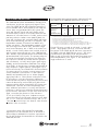
The patients in the START 40/20 Trial were compared to
the START Sr-90 and START Placebo groups. The principal effectiveness and safety results are presented in
Tables 2 and 3 followed by the freedom from target vessel
failure Kaplan-Meier curve, Figure 2. The mean lesion
length studied was 17.4 mm.
*18.4 and 23 Gray reflect the NIST-recommended
adjustments to the documented doses as described in
Technical Report DSGN-0311-A and are equivalent to
the 16 and 20 Gray documented doses described in the
START 40/20 Trial.
17
D03745 Rev. D
03/08
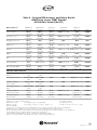
Table 2. Principal Effectiveness and Safety Results
All Patients Treated (N=439)
START 40/20 versus START Placebo
Efficacy Measures
8 Month Stent Segment Binary Restenosis Rate
8 Month Analysis Segment Binary Restenosis Rate
TLR-Free at 240 Days*
TVR-Free at 240 Days*
TVF-Free at 240 Days*
MACE-Free at 240 Days*
Target Lesion Success
Procedure Success
Device Success
Post-Procedure Stent Segment Minimal Lumen
Diameter (MLD, in mm)
Mean± SD (N)
Range (min, max)
Post-Procedure Analysis Segment Minimal Lumen
Diameter (MLD, in mm)
Mean± SD (N)
Range (min, max)
Post-Procedure Stent Segment Percent
Diameter Stenosis (% DS)
Mean± SD (N)
Range (min, max)
Post-Procedure Analysis Segment Percent
Diameter Stenosis (% DS)
Mean± SD (N)
Range (min, max)
Follow-Up Stent Segment Minimal Lumen
Diameter (MLD, in mm)
Mean± SD (N)
Range (min, max)
Follow-Up Analysis Segment Minimal Lumen
Diameter (MLD, in mm)
Mean± SD (N)
Range (min, max)
Follow-Up Stent Segment Percent Diameter
Stenosis (% DS)
Mean± SD (N)
Range (min, max)
Follow-Up Analysis Segment Percent Diameter
Stenosis (% DS)
Mean± SD (N)
Range (min, max)
Safety Measures and Other Clinical Events to
In-Hospital MACE
Out-of-Hospital MACE to 240 Days
In- and Out-of-Hospital MACE to 240 Days
Aneurysm
Stent Thrombosis (to 30 days)
Site Thrombosis (Days 31-240)
Total Occlusions (Angiographic)
Difference
[95% C.I.]
-25.7% [-34.9%, -16.6%]
-19.9% [-29.8%, -9.9%]
12.6% [4.4%, 20.8%]
9.3% [0.6%, 18.1%]
7.8% [-1.2%, 16.9%]
7.8% [-1.2%, 16.9%]
-3.5% [-6.5%,-0.5%]
-3.3% [-7.2%, 0.7%]
-1.2% [-4.3%, 1.9%]
P-value
0.0000
0.0002
0.0008
0.0174
0.0559
0.0559
0.0197
0.1017
0.4315
2.15± 0.42 (229)
(1.20, 3.40)
-0.06 [-0.14, 0.02]
0.1292
1.84± 0.39 (196)
(0.61, 2.89)
1.94± 0.41 (230)
(0.98, 3.10)
-0.10 [-0.18, -0.03]
0.0078
23.8%± 15.7% (196)
(-13.4%, 66.0%)
22.9%± 12.9% (229)
(-19.6%, 51.9%)
0.8% [-1.9, 3.6%]
0.5432
33.2%± 14.2% (196)
(-3.1%, 74.0%)
30.7± 11.0% (230)
(5.8%, 62.5%)
2.4% [0.0, 4.9%]
0.0461
1.85± 0.65 (149)
(0.00, 3.41)
1.47± 0.60 (187)
(0.00, 2.65)
0.38 [-0.24, 0.51]
0.0000
1.60± 0.58 (150)
(0.00, 3.16)
1.41± 0.58 (186)
(0.00, 2.66)
0.19 [0.06, 0.31]
0.0034
30.7%± 23.1% (149)
(-8.0%, 100.0%)
47.9± 20.8% (187)
(-4.4%, 100.0%)
-17.2% [-21.9, -12.5%]
0.0000
40.2%± 20.1% (150)
(2.4%, 100.0%)
240 days
1.9% (4/207)
17.9% (37/207)
19.3% (40/207)
0.7% (1/150)
0.0% (0/207)
1.0% (2/207)
3.3% (5/150)
50.1± 19.7% (188)
(13.4%, 100.0%)
-9.9% [-14.2, -5.7%]
0.0000
-0.2% [-2.9%, 2.4%]
-6.3% [-14.3%, 1.3%]
-6.5% [-14.3%, 1.3%]
0.7% [-0.6%, 2.0%]
0.4% [1.3%, 0.4%]
1.0% [-0.4%, 2.3%]
-0.4% [-4.3%, 3.6%]
0.8694
0.1089
0.1030
0.2622
0.3443
0.1335
0.8473
Numbers are % (counts/sample size) or Mean ± SD.
START 40/20
(N=207 Patients)
15.4% (23/149)
25.3% (38/150)
88.2%
83.1%
80.0%
80.0%
95.7% (198/207)
93.7% (194/207)
96.6% (200/207)
START Placebo
(N=232 Patients)
41.2% (77/187)
45.2% (85/188)
75.6%
73.8%
72.2%
72.2%
99.1% (230/232)
97.0% (225/232)
97.8% (227/232)
2.09± 0.40 (196)
(1.02, 3.33)
CI = Confidence Interval
Relative Risk = START 40/20/START Placebo SE = sqrt{(1-p1)/n11+(1-p2)/n21} CI = RR*exp(±1.96*SE)
Difference = START 40/20 – START Placebo
SE = sqrt(p1*q1/n1+p2*q2/n2)
CI = Diff±1.96*SE
N/A = Not applicable.
Target Lesion Success = Attainment of a final residual stenosis of <50% (by QCA) using any percutaneous method.
If QCA was not available, the visual estimate of diameter stenosis was used.
Procedure Success = Attainment of a final residual stenosis of <50% (by QCA) using any percutaneous method and
no in-hospital major adverse cardiac events (MACE). If QCA was not available, the visual estimate of diameter
stenosis was used.
Device Success = Successful delivery of the Beta-Cath™ System.
Stent segment was defined as the area confined to the proximal and distal borders of the stent.
Analysis segment was defined as the segment that extends 5 mm proximal and distal to the radiated or injured
landmark, whichever was longest in length.
*Survival estimates from Kaplan-Meier method. Standard error estimate from Peto formula.
TLR-free = Freedom from target lesion revascularization.
TVR-free = Freedom from target vessel revascularization.
TVF-free = Freedom from death, MI, and target vessel revascularization.
18
D03745 Rev. D
03/08
2.2%
24.1%
25.9%
0.0%
0.4%
0.0%
3.7%
(5/232)
(56/232)
(60/232)
(0/188)
(1/232)
(0/232)
(7/188)
Relative Risk
[95% C.I.]
0.4 [0.25, 0.57]
0.6 [0.41, 0.77]
1.17 [1.05, 1.29]
1.13 [1.01, 1.26]
1.11 [0.98, 1.25]
1.11 [0.98, 1.25]
1.0 [0.93, 1.00]
1.0 [0.93, 1.01]
1.0 [0.96, 1.02]
0.9 [0.24, 3.29]
0.7 [0.51, 1.07]
0.7 [0.52, 1.06]
-[-,-]
0.0 [-,-}
-[-,-]
0.9 [0.29, 2.76]
MACE-free = Freedom from death, MI, emergent CABG, and target vessel revascularization.
In-Hospital MACE = Death, Q wave or non-Q wave MI, emergent CABG, or target vessel revascularization prior to
discharge as determined by the independent Clinical Events Committee.
Out-of-Hospital MACE = Death, Q wave or non-Q wave MI, emergent CABG, or target vessel revascularization
from hospital discharge through the 240-day contact, as determined by the independent Clinical Events Committee.
Stent thrombosis was defined as angiographic thrombus or subacute closure within the target vessel at the time of
the clinically driven angiographic restudy for documented ischemia (chest pain and ECG changes). Any death not
attributed to a non-cardiac cause within the first 30 days was considered a surrogate for thrombosis in the absence
of documented angiographic stent patency.
Site thrombosis was defined as myocardial infarction attributable to the target vessel with angiographic documentation (site-reported or by QCA) of thrombus or total occlusion at the target site >30 days after the index procedure in
the absence of an intervening revascularization of the target vessel.
Aneurysm was defined as an expansion of the lumen by at least 20% compared with the normal lumen dimensions
in the treatment region (analyzed segment) that extends with a wide or narrow mouth beyond the apparent normal
contour.
Total Occlusion = An MLD of zero at follow-up as assessed by QCA.
Table 3. Principal Effectiveness and Safety Results
All Patients Treated (N=451)
START 40/20 versus START Sr-90
Efficacy Measures
8 Month Stent Segment Binary Restenosis Rate
8 Month Analysis Segment Binary Restenosis Rate
TLR-Free at 240 Days*
TVR-Free at 240 Days*
TVF-Free at 240 Days*
MACE-Free at 240 Days*
Target Lesion Success
Procedure Success
Device Success
Post-Procedure Stent Segment Minimal Lumen
Diameter (MLD, in mm)
Mean± SD (N)
Range (min, max)
Post-Procedure Analysis Segment Minimal Lumen
Diameter (MLD, in mm)
Mean± SD (N)
Range (min, max)
Post-Procedure Stent Segment Percent
Diameter Stenosis (% DS)
Mean± SD (N)
Range (min, max)
Post-Procedure Analysis Segment Percent
Diameter Stenosis (% DS)
Mean± SD (N)
Range (min, max)
Follow-Up Stent Segment Minimal Lumen
Diameter (MLD, in mm)
Mean± SD (N)
Range (min, max)
Follow-Up Analysis Segment Minimal Lumen
Diameter (MLD, in mm)
Mean± SD (N)
Range (min, max)
Follow-Up Stent Segment Percent Diameter
Stenosis (% DS)
Mean± SD (N)
Range (min, max)
Follow-Up Analysis Segment Percent Diameter
Stenosis (% DS)
Mean± SD (N)
Range (min, max)
Safety Measures and Other Clinical Events to
In-Hospital MACE
Out-of-Hospital MACE to 240 Days
In- and Out-of-Hospital MACE to 240 Days
Aneurysm†
Stent Thrombosis (to 30 days)
Site Thrombosis (Days 31-240)
Total Occlusions (Angiographic)
START 40/20
(N=207 Patients)
15.4% (23/149)
25.3% (38/150)
88.2%
83.1%
80.0%
80.0%
95.7% (198/207)
93.7% (194/207)
96.6% (200/207)
START Sr-90
(N=244 Patients)
14.2% (28/197)
28.8% (57/198)
86.4%
83.5%
81.4%
81.4%
99.6% (243/244)
97.1% (237/244)
98.4% (240/244)
2.09± 0.40 (196)
(1.02, 3.33)
Difference
[95% C.I.]
1.2% [-6.4%, 8.8%]
-3.5% [-12.8%, 5.9%]
1.8% [-5.2%, 8.8%]
-0.4% [-8.1%, 7.4%]
-1.4% [-9.5%, 6.8%]
-1.4% [-9.5%, 6.8%]
-3.9% [-6.8%, -1.0%]
-3.4% [-7.3%, 0.5%]
-1.7% [-4.7%, 1.2%]
P-value
0.7507
0.4738
0.4516
0.8750
0.8724
0.8724
0.0047
0.0795
0.2320
2.17± 0.42 (242)
(1.12, 3.47)
-0.08 [-0.16, -0.00]
0.0489
1.84± 0.39 (196)
(0.61, 2.89)
1.94± 0.39 (243)
(1.03, 3.02)
-0.10 [-0.17, -0.03]
0.0073
23.8%± 15.7% (196)
(-13.4%, 66.0%)
22.9± 13.5% (243)
(-31.1%, 53.2%)
0.8% [-1.9, 3.6%]
0.5479
33.2%± 14.2% (196)
(-3.1%, 74.0%)
31.4%± 10.2% (243)
(6.7%, 57.6%)
1.8% [-0.5, 4.1%]
0.1329
1.85± 0.65 (149)
(0.00, 3.41)
1.96± 0.66 (197)
(0.00, 3.45)
-0.11 [0.25, 0.03]
0.1088
1.60± 0.58 (150)
(0.00, 3.16)
1.65± 0.64 (198)
(0.00, 3.18)
-0.05 [-.18, 0.08]
0.4252
30.7%± 23.1% (149)
(-8.0%, 100.0%)
30.4± 22.7% (197)
(-32.2%, 100.0%)
0.3% [-4.6, 5.2%]
0.8991
40.2%± 20.1% (150)
(2.4%, 100.0)
240 days
1.9% (4/207)
17.9% (37/207)
19.3% (40/207)
0.7% (1/150)
0.0% (0/207)
1.0% (2/207)
3.3% (5/150)
41.7± 20.7% (198)
(-10.4%, 100.0%)
-1.5% [-5.8, 2.9%]
0.5046
-0.5% [-3.2%, 2.2%]
1.9% [-5.1%, 8.8%]
1.3% [-5.9%, 8.5%]
0.2% [-1.5%, 1.8%]
0.0% [-,-]
1.0% [-0.4%, 2.3%]
-0.7% [-4.7%, 3.3%]
0.7051
0.5930
0.7257
0.8434
0.1238
0.7305
Numbers are % (counts/sample size) or Mean ± SD.
CI = Confidence Interval
Relative Risk = START 40/20 Sr-90/START Sr-90
SE = sqrt{(1-p1)/n11+(1-p2)/n21} CI = RR*exp(±1.96*SE)
Difference = START 40/20 Sr-90 – START Sr-90
SE = sqrt(p1*q1/n1+p2*q2/n2)
CI = Diff±1.96*SE
N/A = Not applicable.
Target Lesion Success = Attainment of a final residual stenosis of <50% (by QCA) using any percutaneous method.
If QCA was not available, the visual estimate of diameter stenosis was used.
Procedure Success = Attainment of a final residual stenosis of <50% (by QCA) using any percutaneous method
and no in-hospital major adverse cardiac events (MACE). If QCA was not available, the visual estimate of diameter stenosis was used.
Device Success = Successful delivery of the Beta-Cath™ System.
Footnotes are continued on the following page.
Stent segment was defined as the area confined to the proximal and distal borders of the stent.
Analysis segment was defined as the segment that extends 5 mm proximal and distal to the radiated or injured
landmark, whichever was longest in length.
*Survival estimates from Kaplan-Meier method. Standard error estimate from Peto formula.
TLR-free = Freedom from target lesion revascularization.
TVR-free = Freedom from target vessel revascularization.
2.5%
16.0%
18.0%
0.5%
0.0%
0.0%
4.0%
(6/244)
(39/244)
(44/244)
(1/198)
(0/244)
(0/244)
(8/198)
Relative Risk
[95% C.I.]
1.1 [0.65, 1.81]
0.9 [0.62, 1.25]
1.02 [0.94, 1.11]
1.00 [0.91, 1.09]
0.98 [0.89, 1.09]
0.98 [0.89, 1.09]
1.0 [0.93, 0.99]
1.0 [0.93, 1.01]
1.0 [0.95, 1.01]
0.8 [0.22, 2.75]
1.1 [0.74, 1.68]
1.1 [0.73, 1.58}
1.3 [0.08, 20.93]
- [-,-]
- [-,-]
0.8 [0.28, 2.47]
MACE-free = Freedom from death, MI, emergent CABG, and target vessel revascularization.
In-Hospital MACE = Death, Q wave or non-Q wave MI, emergent CABG, or target vessel revascularization prior to
discharge as determined by the independent Clinical Events Committee.
Out-of-Hospital MACE = Death, Q wave or non-Q wave MI, emergent CABG, or target vessel revascularization
from hospital discharge through the 240-day contact, as determined by the independent Clinical Events Committee.
Stent thrombosis was defined as angiographic thrombus or subacute closure within the target vessel at the time of
the clinically driven angiographic restudy for documented ischemia (chest pain and ECG changes). Any death not
attributed to a non-cardiac cause within the first 30 days was considered a surrogate for thrombosis in the absence
of documented angiographic stent patency.
Site thrombosis was defined as myocardial infarction attributable to the target vessel with angiographic documentation (site-reported or by QCA) of thrombus or total occlusion at the target site >30 days after the index procedure
in the absence of an intervening revascularization of the target vessel.
Aneurysm was defined as an expansion of the lumen by at least 20% compared with the normal lumen dimensions
in the treatment region (analyzed segment) that extends with a wide or narrow mouth beyond the apparent normal
contour.
†Baseline QCA for START Sr-90 patient 15/3 revealed the presence of an aneurysm. The Angiographic Core
Laboratory reported the absolute size of the aneurysm changed very little from baseline to follow-up and that the
larger appearance at follow-up was due to the smaller reference vessel dimension rather than an increase in
aneurysm size.
Total Occlusion = An MLD of zero at follow-up as assessed by QCA.
TVF-free = Freedom from death, MI, and target vessel revascularization.
19
D03745 Rev. D
03/08
Figure 2. Freedom from Target Vessel Failure (at 240 days)
Event-free Survival ± 1.5SE; All Patients Treated (N=439)
START 40/20 versus START Placebo
Freedom from TVF
100%
90%
80%
70%
START 40/20
START Placebo
60%
0
30
60
90
120
150
180
210
240
Time after initial procedure (days)
Time after initial procedure (days)
START 40/20
# Entered
# Lost to Follow-up
# Incomplete
# At risk
# Events
# Events/Month
% Survived
% SE
START Placebo
# Entered
# Lost to Follow-up
# Incomplete
# At risk
# Events
# Events/Month
% Survived
% SE
0
30
60
90
120
150
180
210
240
207
0
0
206
2
0
207.0
1
205.0
199
2
0
198.0
193
0
0
193.0
189
0
0
189.0
183
1
0
182.5
179
2
0
178.0
174
4
0
172.0
162
14
0
155.0
5
5
97.1%
4
4
95.1%
4
4
93.2%
6
6
90.2%
3
3
88.7%
3
3
87.2%
8
8
83.2%
6
6
80.0%
1.2%
1.5%
1.8%
2.1%
2.2%
2.4%
2.7%
3.0%
232
230
216
209
198
185
175
166
156
0
0
232.0
8
0
226.0
2
0
215.0
2
0
208.0
0
0
198.0
0
0
185.0
4
0
173.0
7
0
162.5
31
0
140.5
2
6
6
96.5%
1.2%
5
5
94.3%
1.6%
9
9
90.2%
2.0%
13
13
84.3%
2.5%
10
10
79.7%
2.7%
5
5
77.4%
2.9%
3
3
76.0%
3.0%
7
7
72.2%
3.5%
Deg Frdm
1
P-Value
0.0559
1
0.0590
99.5%
0.5%
99.1%
0.6%
Test Between Groups
Chi-Square
Test
3.66
Wilcoxon
Log-Rank
3.57
20
D03745 Rev. D
03/08
RENO-Long Sub-Analysis
The European Surveillance REgistry with the
NOvoste Beta-Cath™ System (RENO) Long
Subgroup, a sub-analysis of 139 of the 1098 patients
treated with the Beta-Cath™ (5F) System in the RENO
Registry (a prospective commercial registry at 46 centers
in Europe), began June 1, 1999. The RENO-Long subgroup focused on patients with diffuse in-stent restenotic
lesions in single vessels treated by longer than 40 mm of
radiation source train. Treatments with the Beta-Cath™
(5F) System included stepping (pullback)1 procedures utilizing 30, 40 or 60 mm source trains or a single 60 mm
source train. The acute and follow-up (6-month for
RENO-Long and WRIST/Long WRIST and 8-month for
START) clinical and angiographic results demonstrated
that the procedural success rate, defined as the attainment of a residual stenosis <30% diameter stenosis at the
time of intervention with successful delivery radiation
therapy was 89.9% (124/138) as compared to 81.7%
(76/93) in the WRIST/Long Wrist Control Group, 97.0%
(225/232) in the START Placebo Group, and 97.1%
(237/244) In the START Radiation Group. Freedom
from MACE (6-month for RENO-Long and WRIST/Long
WRIST and 8-month for START) was 82.1% (110/134)
as compared to 35.1% (33/94) in the WRIST/Long
Wrist Control Group (p<0.0001), 74.1% (172/232) in
the START Placebo Group (p=0.0937), and 82.0%
(200/244) In the START Radiation Group (p>0.9999).
Freedom from TVR (6-month for RENO-Long and
WRIST/Long WRIST and 8-month for START) was 85.1%
(110/134) as compared to 39.4% (37/94) in the
WRIST/Long Wrist Control Group (p<0.0001), 75.9%
(176/232) in the START Placebo Group (p=0.0444),
and 84.0% (205/244) in the START Radiation Group
(p>0.8825).
A total of 139 patients of the 1098 enrolled in 46 centers in Europe were analyzed in the RENO-Long subgroup. Radiation was prescribed in the RENO registry
according to the following schema:
Without stent:
• 16.1 Gray at 2 mm if a maximum balloon diameter of
2.5 mm 3.5 mm was used; or
• 20.7 Gray at 2 mm if a maximum balloon diameter of
> 3.5 mm < 4.0 mm was used; or
• 23.0 Gray at 2 mm if a maximum balloon diameter of
4.0 mm was used
≥
≤
≥
With stent implantation (In-stent-restenosis or radiation
after stent implantation):
• 18.4 Gray at 2 mm if a maximum balloon diameter of
2.5 mm 3.5 mm was used; or
• 23 Gray at 2 mm if a maximum balloon diameter of
> 3.5 mm < 4.0 mm was used; or
• 25.3 Gray at 2 mm if a maximum balloon diameter of
4.0 mm was used
≥
≤
≥
Additionally, a comparison of the patients treated with
stepping (pullback)1 or a single 60 mm source train within the RENO-Long Subgroup demonstrated that the procedural success rate for the pullback group was 88.9%
(96/109) as compared to 93.3% (28/30) in the 60 mm
group. Freedom from MACE (6-month) was 81.0%
(85/105) for the pullback group as compared to 86.2%
(25/29) in the in the 60 mm group (p=0.5963).
Freedom from TVR (6-month) was 83.8% (88/105) for
the pullback group as compared to 89.7% (26/29) in
the 60 mm group (p=0.5639).
1
The Beta-Cath™ System is not indicated for pullback (stepping).
21
D03745 Rev. D
03/08
The antiplatelet/anticoagulant regime administered for
RENO was assessed with two questionnaires that were
sent to investigators to define the prescribed duration of
antiplatelet therapy. The first questionnaire was sent in
July 1999 (3 months after patient recruitment had
begun), and the second in April 2001 (at the time the last
patients were followed-up for their 6-month visit). The survey demonstrated that most patients received greater than
at least 6 months of antiplatelet therapy. The results of
the survey are as follows:
Duration of combined antiplatelet regimen following VBT in the RENO Registry
100%
80%
60%
%
40%
20%
0%
new stent
1999
new stent
2001
less than 3 months
6 months
no new
stent 1999
no new
stent 2001
3 months
12 months or more
As reported in article submitted by Philip Urban, M.D., FACC, for publication in JACC, entitled: A multicenter
European Registry of Intraluminal Coronary Beta Brachytherapy.
22
D03745 Rev. D
03/08
Table 4. Principal Effectiveness and Safety Results
RENO Long versus WRIST/Long WRIST Control
All Patients Treated (N=233)
RENO-Long
(N=139)
Wrist/Long
Wrist Control
(N=94)
Combined
(N=233)
Relative Risk
[95% C.I.]
Difference
[95% C.I.]
p Value
96.4%
100.0%
97.9%
0.96
-3.60%
0.0834
(134/139)
(94/94)
(228/233)
[0.93, 1.00]
[-7.60, 0.40]
89.9%
81.7%
86.6%
1.10
8.13%
(124/138)
(76/93)
(200/231)
[0.98, 1.23]
[-2.14, 18.41]
99.3%
89.2%
95.3%
1.11
10.03%
(138/139)
(83/93)
(221/232)
[1.04, 1.20]
[2.65, 17.42]
82.1%
35.1%
62.7%
2.34
46.98%
(110/134)
(33/94)
(143/228)
[1.76, 3.11]
[34.39, 59.57]
85.1%
39.4%
66.2%
2.16
45.71%
(114/134)
(37/94)
(151/228)
[1.67, 2.81]
[33.18, 58.25]
17.9%
64.9%
37.3%
0.28
-46.98%
(24/134)
(61/94)
(85/228)
[0.19, 0.41]
[-59.57, -34.39]
14.9%
60.6%
33.8%
0.25
-45.71%
(20/134)
(57/94)
(77/228)
[0.16, 0.38]
[-58.25, -33.18]
2.3%
11.7%
6.2%
0.20
-9.41%
(3/131)
(11/94)
(14/225)
[0.06, 0.68]
[-17.35, -1.48]
16.4%
61.7%
35.1%
0.27
-45.28
(22/134)
(58/94)
(80/228)
[0.18, 0.40]
[-57.90, -32.66]
0.15 ± 0.71
0.85 ± 0.57
0.59 ± 0.71
N/A
(49)
(81)
(130)
0.11 ± 0.90
1.00 ± 0.66
0.67 ± 0.87
(49)
(80)
(129)
-1.34± 7.32
1.37 ± 4.78
0.34 ± 6.00
(49)
(80)
(129)
0.01 ± 0.60
0.86 ± 0.61
0.54 ± 0.73
(49)
(79)
(128)
Binary Restenosis
28.6%
76.5%
58.5%
0.37
-47.97%
Rate at 6 Months
(14/49)
(62/81)
(76/130)
[0.24, 0.59]
[-65.41,- 30.54]
Efficacy Measure
Follow- up Done
Procedure Success
Brachytherapy Success
MACE –Free at 6 months
TVR Free at 6 month
MACE at 6-months
TVR at 6-months
In-Hospital MACE
Out of Hospital
MACE to 6 months
0.0805
0.0006
<.0001
<.0001
<.0001
<.0001
0.0050
<.0001
CORE LAB SUBSET ANALYSIS
In-Analysis Segment
Late Loss at 6 months
Stent Segment Late
Loss at 6 months
-0.70
<.0001
[-0.92, -0.48]
N/A
-0.89
<.0001
[-1.16, -0.61]
In-Analyisis Segment
Late Loss Index at 6
Months
N/A
-2.71
0.0240
[-4.82, -0.60]
Stent Segment Late
Loss Index at 6
Months
N/A
-0.85
<.0001
[-1.07, -0.63]
In-Analysis Segment
<.0001
Stent Segment Binary
Restenosis Rate
20.4%
70.0%
51.2%
0.29
-49.59%
at 6 Months
(10/49)
(56/80)
(66/129)
[0.16, 0.52]
[-66.47, -32.71]
Numbers are % (counts/n) or Mean ± SD (n)
Relative Risk = p1/p2
SE = sqrt {((1-p1)/n1 p1, + ((1-p2/n2p2)}
SE + sqrt {(p1* (1-p1)/(n1 - 1) + p2* (1 - p2)/(n2 - 1)}
Difference = p_/p_
<.0001
CI= Confidence Interval
CI = RR* exp (±1.96* SE)
CI = diff. ± (1.96* SE + 0.5* (1/n1 + 1/n2))
NA = Not applicable
Procedure Success = Attainment of a <50% residual diameter stenosis using any percutaneous method and no in-hospital MACE.
Brachytherapy Success = Attainment of a <50% residual stenosis and successful delivery of the radiation device.
Restenosis was defined at 50% in-stent diameter stenosis at the follow-up angiogram. If an in-stent measurement was not available, the
In-lesion diameter was used. In-Analysis Segment = Stent + Probe + Edges areas.
*Survival Estimates from Kaplan-Meier estimate. Standard Error estimate by Peto formula.
Mace-Free = No Death, Q Wave of Non-Q Wave MI, CABG, or Target Vessel Revascularization.
≥
23
D03745 Rev. D
03/08
Figure 3. Principal Effectiveness and Safety Results
RENO Long versus WRIST/Long WRIST Control
6-Month Freedom from MACE
1.0
Survival Probability
0.9
0.8
0.7
0.6
0.5
0.4
0.3
0.2
0.1
Sr-90
Placebo
0.0
0
30
60
90
120
150
180
Time in days
Summary Statistics
RENO
Control
Total
134
94
Events Censored
24
110
61
33
Tests Between Groups
Log-Rank
Wilcoxon
24
D03745 Rev. D
03/08
Chi-Square
49.6
55.2
d.o.f.
1
1
P Value
< .0001
< .0001
Event Free %
82.09%
35.11%
210
Table 5. Principal Effectiveness and Safety Results
RENO-Long versus START Placebo
All Patients Treated (N=371)
Efficacy Measure
RENO-Long
START Placebo
Combined
Relative Risk
Difference
(N=139)
(N=232)
(N=371)
[95% C.I]
[95% C.I.]
p Value
96.4%
100.0%
98.7%
0.96 [0.93, 1.00]
-3.60%
0.0060
(134/139)
(244/244)
(378/383)
89.9%
97.0%
94.3%
(124/138)
(225/232)
(349/370)
99.3%
N/A
99.3%
Follow- up Done
Procedure Success
Brachytherapy Success
[-7.27, 0.07]
0.93 [0.87, 0.98]
-7.13%
0.0088
[-13.22, -1.03]
N/A
N/A
N/A
1.11 [0.99, 1.24]
7.95%
0.0937
1.12 [1.01, 1.24]
9.21% [0.43, 17.99]
0.0444
0.69
-7.95%
0.0937
(138/139)
(138/139)
82.1%
74.1%
77.0%
(110/134)
(172/232)
(282/366)
85.1%
75.9%
79.2%
(114/134)
(176/232)
(290/366)
17.9%
25.9%
23.0%
(24/134)
(60/232)
(84/336)
[0.45, 1.06]
[-17.16, 1.26]
14.9%
24.1%
20.8%
0.62 [0.39, 0.98]
-9.21%
(20/134)
(56/232)
(76/366)
2.2%
2.2% (5/232)
2.2%
MACE –Free
TVR Free
MACE
TVR
In-Hospital MACE
(3/139)
[-1.26, 17.16]
0.0444
[-17.99, -0.43]
1.00 [0.24, 4.13]
0.00%
(8/371)
>0.9999
[-3.64, 3.64]
16.4%
24.1%
21.3%
0.68
-7.72%
(22/134)
(56/232)
(78/366)
[0.44, 1.06]
[-16.68, 1.24]
0.15+/- 0.71
0.55+/-0.59
N/A
N/A
-0.40 [-0.59, -0.21]
0.0006
N/A
N/A
-0.56 [-0.77, -0.35]
0.0001
N/A
N/A
-2.18 [-3.60, -0.76]
0.0476
N/A
N/A
-0.56 [-0.75, -0.37]
<.0001
0.63 [0.40, 1.01]
-16.64%
0.0502
Out of Hospital MACE
0.0867
CORE LAB SUBSET ANALYSIS
In-Analysis Segment
Late Loss
(49)
(188)
Stent Segment Late Loss
0.11+/-0.90
0.67+/-0.61
(49)
(187)
In-Analysis Segment
-1.34+/-7.32
0.84+/-3.41
Late Loss Index
Stent Segment Late Loss
(49)
(187)
0.01+/-0.60
0.57+/-0.60
(49)
(186)
In-Analysis Segment
28.6%
45.2%
41.8%
Binary Restenosis Rate
(14/49)
(85/188)
(99/237)
Stent Segment Binary
20.4%
41.2%
36.9%
Restenosis Rate
(10/49)
(77/187)
(87/236)
Index
Numbers are % (counts/n) or Mean ± SD (n)
Relative Risk = p1/p2
SE = sqrt {((1-p1)/n1 p1, + ((1-p2)/n2p2)}
Difference = p1/p2
SE + sqrt {(p1* (1-p1)/(n1 - 1) + p2* (1 - p2)/(n2 - 1)}
[-32.56, -0.72]
0.50 [0.28, 0.88]
-20.77%
0.0077
[-35.47, -6.06]
CI= Confidence Interval
CI = RR* exp (±1.96* SE)
CI = diff. ± (1.96* SE + 0.5* (1/n1 + 1/n2))
NA = Not applicable
Procedure Success = Attainment of a <50% residual diameter stenosis using any percutaneous method and no in-hospital MACE.
Brachytherapy Success = Attainment of a <50% residual stenosis and successful delivery of the radiation device.
Restenosis was defined at 50% in-stent diameter stenosis at the follow-up angiogram. If an in-stent measurement was not available, the
In-lesion diameter was used. In-Analysis Segment = Stent + Probe + Edges areas.
*Survival Estimates from Kaplan-Meier estimate. Standard Error estimate by Peto formula.
Mace-Free = No Death, Q Wave of Non-Q Wave MI, CABG, or Target Vessel Revascularization.
≥
25
D03745 Rev. D
03/08
Table 6. Principal Effectiveness and Safety Results
RENO-Long versus START Radiation
All Patients Treated (N=383)
Efficacy Measure
RENO-Long
(N=139)
96.4%
(134/139)
89.9%
(124/138)
99.3%
(138/139)
82.1%
(110/134)
85.1%
(114/134)
17.9%
(24/134)
14.9%
(20/134)
2.3%
(3/131)
16.4%
(22/134)
Follow- up Done
Procedure Success
Brachytherapy Success
MACE–Free
TVR-Free
MACE
TVR
In-Hospital MACE
Out of Hospital MACE
START Radiation
(N=244)
100.00%
(244/244)
97.1%
Combined
(N=383)
98.6%
(378/383)
94.5%
Relative Risk
[95% C.I]
N/A
Difference
[95% C.I.]
N/A
0.93 [0.87, 0.98]
(361/382)
N/A
N/A
-7.28%
[-13.32, -1.23]
N/A
0.0042
(237/244)
N/A
82.0%
(200/244)
84.0%
(205/244)
18.0%
(44/244)
16.0%
(39/244)
2.5%
(6/244)
16.0%
(39/244)
82.0%
(310/378)
84.4%
(319/378)
18.0%
(68/378)
15.6%
(59/378)
2.4%
(9/375)
16.1%
(61/378)
0.12%
[-8.57, 8.81]
1.06%
[-7.13, 9.25]
-0.12%
[-8.81, 8.57]
-1.06%
[-9.25, 7.13]
-0.17%
[-3.98, 3.64]
0.43%
[-7.95, 8.81]
>0.9999
0.15+/-0.71
(49)
0.11+/-0.90
(49)
-1.34+/-7.32
(49)
0.01+/-0.60
(49)
28.6%
(14/49)
20.4%
0.28+/-0.56
(198)
0.21+/-0.61
(197)
0.35+/-1.06
(198)
0.09+/-1.28
(197)
28.8%
(57/198)
14.2%
N/A
N/A
-0.13 [-0.32, 0.06]
0.2373
N/A
N/A
-0.10 [-0.31, 0.11]
0.4641
N/A
N/A
-1.69 [-2.75, -0.63]
0.1135
N/A
N/A
-0.08 [-0.45, 0.29]
0.5236
28.7%
(71/247)
15.4%
0.99 [0.61, 1.63]
-0.22%
[-15.75, 15.32]
6.19%
>0.9999
(10/49)
(28/197)
(38/246)
1.00 [0.91, 1.11]
1.01 [0.93, 1.11]
0.99 [0.63, 1.56]
0.93 [0.57, 1.53]
0.93 [0.24, 3.66]
1.03 [0.64, 1.66]
p Value
N/A
N/A
0.8825
>0.9999
0.8825
>.0.9999
>0.9999
CORE LAB SUBSET ANALYSIS
In-Analysis Segment
Late Loss
Stent Segment Late Loss
In-Analyisis Segment
Late Loss Index
Stent Segment Late Loss
Index
In-Analysis Segment
Binary Restenosis Rate
Stent Segment Binary
Restenosis Rate
Numbers are % (counts/n) or Mean ± SD (n)
Relative Risk = p1/p2
SE = sqrt {((1-p1)/n1 p1, + ((1-p2)/n2p2)}
Difference = p1/p2
SE + sqrt {(p1* (1-p1)/(n1 - 1) + p2* (1 - p2)/(n2 - 1)}
1.44 [0.75, 2.75]
[-7.48, 19.87]
CI= Confidence Interval
CI = RR* exp (±1.96* SE)
CI = diff. ± (1.96* SE + 0.5* (1/n1 + 1/n2))
NA = Not applicable
Procedure Success = Attainment of a <50% residual diameter stenosis using any percutaneous method and no in-hospital MACE.
Brachytherapy Success = Attainment of a <50% residual stenosis and successful delivery of the radiation device.
Restenosis was defined at 50% in-stent diameter stenosis at the follow-up angiogram. If an in-stent measurement was not available, the
In-lesion diameter was used. In-Analysis Segment = Stent + Probe + Edges areas.
*Survival Estimates from Kaplan-Meier estimate. Standard Error estimate by Peto formula.
Tlr-Free= No Target Lesion Revascularization, Mace-Free = No Death, Q Wave of Non-Q Wave MI, CABG, or Target Vessel Revascularization.
≥
26
D03745 Rev. D
03/08
0.2767
Table 7. Principal Effectiveness and Safety Results
Pullback1 versus Non-Pullback (60 mm)
All Patients Treated (N=139)
Efficacy Measure
Follow- up Done
Procedure Success
Brachytherapy Success
MACE –Free at 6 months
TVR Free at 6 month
Pullback1
(N=109)
96.3%
(105/109)
88.9%
(96/109)
100.0%
(109/109)
81.0%
(85/105)
83.8%
Non-pullback
(N=30)
96.7%
(29/30)
93.3%
(28/30)
96.7%
(29/30)
86.2%
Combined
(N=139)
96.4%
(134/139)
89.9%
(124/138)
99.3%
(138/139)
82.1%
(25/29)
89.7%
(110/134)
85.1%
(88/105)
19.0%
(20/105)
16.2%
(17/105)
0.9%
(1/109)
18.1%
(19/105)
(26/29)
13.8%
(4/29)
10.3%
(3/29)
6.7%
(2/30)
10.3%
(3/29)
(114/134)
17.9%
(24/134)
14.9%
(20/134)
2.2%
(3/139)
16.4%
(22/134)
0.21 ± 0.74
(37)
0.28 ± 0.95
(37)
-0.02 ± 0.59
(12)
-0.38 ± 0.46
(12)
0.15 ± 0.71
(49)
0.11 ± 0.90
(49)
N/A
-1.68± 8.41
(37)
0.12 ± 0.61
(37)
-0.28 ± 0.95
(12)
-0.31 ± 0.44
(12)
-1.34 ± 7.32
(49)
0.01 ± 0.60
(49)
N/A
35.1%
(13/37)
8.3% (1/12)
28.6% (14/49)
27.0%
(10/37)
0.0%
(0/12)
20.4% (10/49)
MACE at 6-months
TVR at 6-months
In-Hospital MACE
Out of Hospital MACE
to 6 months
Relative Risk
1.00 [0.92, 1.08]
0.94 [0.79, 1.12]
Difference
-0.34%
[-9.90, 9.22]
-4.44%
[-17.43, 8.54]
3.33%
[-5.33, 11.99]
-5.25%
0.93 [0.80, 1.09]
[-22.29, 11.78]
-5.85%
0.95 [0.85, 1.07]
1.03 [0.97, 1.11]
1.38 [0.51, 3.72]
1.57 [0.49, 4.97]
0.14 [0.01, 1.47]
1.75 [0.56, 5.50]
[-21.36, 9.67]
5.25%
[-11.78, 22.29]
5.85%
[-9.67, 21.36]
-5.75%
[-17.13, 5.63]
7.75%
[-7.94, 23.44]
P Value
>0.9999
0.7342
0.2158
0.5963
0.5639
0.5963
0.5639
0.1175
0.4057
CORE LAB SUBSET ANALYSIS
In-Analysis Segment
Late Loss at 6 months
Stent Segment Late Loss
at 6 months
In-Analyisis Segment
Late Loss Index at 6
Months
Stent Segment Late
Loss Index at 6 Months
In-Analysis Segment
Binary Restenosis Rate
at 6 Months
Stent Segment Binary
Restenosis Rate
at 6 Months
Numbers are % (counts/n) or Mean ± SD (n)
Relative Risk = p1/p2
SE = sqrt {((1-p1)/n1 p1, + ((1-p2)/n2p2)}
Difference = p1/p2
SE + sqrt {(p1* (1-p1)/(n1 - 1) + p2* (1 - p2)/(n2 - 1)}
0.22
[-0.25, 0.70]
0.66
[0.08, 1.23]
0.3446
1.40
[-6.33, 3.52]
0.43
[0.05, 0.82]
0.3256
4.22
[0.61, 28.96]
26.80%
[-1.30, 54.90]
0.1391
7.18
[0.45, 114.22]
27.03
[7.00, 47.05]
0.0926
N/A
N/A
0.0028
0.0289
CI= Confidence Interval
CI = RR* exp (±1.96* SE)
CI = diff. ± (1.96* SE + 0.5* (1/n1 + 1/n2))
NA = Not applicable
Procedure Success = Attainment of a <50% residual diameter stenosis using any percutaneous method and no in-hospital MACE.
Brachytherapy Success = Attainment of a <50% residual stenosis and successful delivery of the radiation device.
Restenosis was defined at 50% in-stent diameter stenosis at the follow-up angiogram. If an in-stent measurement was not available, the
In-lesion diameter was used. In-Analysis Segment = Stent + Probe + Edges areas.
*Survival Estimates from Kaplan-Meier estimate. Standard Error estimate by Peto formula.
Tlr-Free= No Target Lesion Revascularization, Mace-Free = No Death, Q Wave of Non-Q Wave Mi, Cabg, or Target Vessel Revascularization.
≥
1
The Beta-Cath™ System is not indicated for pullback (stepping).
27
D03745 Rev. D
03/08
IV. Instructions For Use
The following section provides instructions for using the
Beta-Cath™ 3.5F System from Best® Vascular, Inc. The
Beta-Cath™ 3.5F System is designed to be used by a
team of appropriately trained personnel. At a minimum,
this team should include a Cardiologist, Radiation
Oncologist, and Medical Physicist.
Detailed Device Description
The Beta-Cath™ 3.5F System is designed to provide protection to health care workers and to minimize patient
exposure to ionizing radiation. The unique design of the
Transfer Device allows the beta sources to be contained
and shielded during transport and storage without substantially modifying the safety procedures and protocols currently used in Cardiac Catheterization Labs. The BetaCath™ 3.5F System consists of four components; the two
major components are described below:
1) The Transfer Device is a multiple-use, hand-held
device used to store the Source Train and to deliver the
sources to and from the vessel by means of the Delivery
Catheter. The Transfer Device is designed to shield
health care workers from beta radiation. The single-use
Delivery Catheter does not allow the Sources to come
in contact with the patient’s blood or tissue. The
Transfer Device will contain either an ACTIVE or
NON-ACTIVE Source Train. The 3.5F System compatible
Transfer Device is color-coded gray.
The ACTIVE Source Train will contain a wire jacketed
“train” of 12 (30 mm Source Train), 16 (40 mm Source
Train) or 24 (60 mm Source Train) miniature cylindrical
radioactive sealed sources containing 90Strontium/
90
Yttrium (90Sr/90Y), pure beta emitters, and two (one distal and one proximal) radiopaque markers. The principal radiation emission is beta particles with energies up
to 2.27 MeV. 90Sr/90Y has a radioactive half-life of 28.8
years. The long half-life simplifies treatment planning
due to the slow rate of radioactive decay.
The presence of the black and yellow
Radioactive Warning Symbol will identify
the ACTIVE Transfer Device.
An optional NON-ACTIVE Transfer Device will contain a
NON-ACTIVE Source Train consisting of 16 (40 mm
Source Train) miniature cylindrical NON-ACTIVE sources,
and two (one distal and one proximal) radiopaque
markers. This Transfer Device is NOT RADIOACTIVE
and will be labeled NON-ACTIVE .
28
D03745 Rev. D
03/08
2) The Novoste™ b-Rail™ 3.5F Delivery Catheter is a
single-use, closed-end catheter, with a 1 cm distal rail
segment. The Source Train is transported to the treatment site and back into the Transfer Device through the
Delivery Catheter. The Delivery Catheter is compatible
with the 30 mm, 40 mm and 60 mm versions of the
Beta-Cath™ 3.5F System compatible Transfer Device.
The Delivery Catheter is supplied sterile and includes
an Indicator of Source Train (IST) pre-loaded into the
Delivery Catheter, and a Flushing Cannula. The IST aids
in the measurement and positioning of the Delivery
Catheter to ensure placement of the radioactive Source
Train across the entire interventional injury. The
Proprietary Connector connects the Delivery Catheter
exclusively to the Novoste™ Beta-Cath™ 3.5F System
compatible Transfer Device.
How Supplied
The initial Beta-Cath™ 3.5F System shipment will include
the following items:
• ACTIVE Transfer Device and White Lead-Lined
Container in a Type A shipping container
• Start-Up Kit which contains the following items:
• One Transport Case, which includes:
• One Response Kit
• One Temporary Storage Container
• One 5-pack box of Medical Physicist’s Kits
The b-Rail™ 3.5F Delivery Catheter which includes the
Procedure Accessory Pack (supplied sterile) is sold separately.
All items are also sold individually.
Reusable Items
ACTIVE Transfer Device:
The Transfer Device containing the ACTIVE Source Train
will be shipped to the hospital inside a White Lead-Lined
Storage Container in a Type A (for shipping radioactive
material) shipping container. The Transfer Device should
be received by radiation personnel of the institution
according to local regulations and institutional radiation
procedures. After the radiation safety personnel perform
the incoming Device Receipt Procedure, the White LeadLined Storage Container containing the ACTIVE Transfer
Device with the ACTIVE Source Train should be placed in
the Transport Case for movement within your institution
and secured from unauthorized access.
The Transport Case is a plastic (non-sterile) storage case.
It will be shipped to the hospital without radioactive
material and functions only as a storage case (i.e. not a
Type A container) for the following items:
The Transport Case with an ACTIVE Transfer Device
should only be stored in a secure area designated for
radioactive material storage.
The Twin Transport case is provided to those hospitals
which possess two ACTIVE Transfer Devices. It contains
the same items as the single Transport Case, but has an
additional compartment to store a second White-Lead
Lined Storage Container containing the second ACTIVE
Transfer Device.
Twin
Transport
Case
Temporary Storage Container:
The Temporary Storage Container is a clear plastic
(non-sterile) container. This Container is designed to
shield beta radiation and is used to temporarily store
the Beta-Cath™ 3.5F System in the event that the
ACTIVE Source Train is unable to be returned to the
Source Chamber of the ACTIVE Transfer Device.
Single
Transport
Case
• Combination Lock to help secure from unauthorized
access.
• A Response Kit (shipped inside Transport Case):
• Battery-operated flashlight
• Tweezers
• Source Recovery Probe
• Source Container with a screw-on top
(intended for single use)
• Magnifying Glass
• Compartment to store the White Lead-Lined Storage
Container containing the ACTIVE Transfer Device.
• An empty storage compartment.
29
D03745 Rev. D
03/08
Medical Physicist’s Kit:
• A proximal end that consists of a Proprietary
Connector which utilizes squeeze tabs to ensure a
secure connection between the Delivery Catheter
and the Transfer Device.
The Medical Physicist’s Kit contains the disposable accessories required to perform the initial Device Receipt
Procedure and to purge fluid from the Transfer Device.
The Kit contains:
• Working length of 135 cm.
• Overall length of:
- 180 cm b-Rail 3.5F Delivery Catheter
- 267 cm b-Rail 3.5F XL Delivery Catheter
• two (2) 3.5F Flushing Adapters
• two (2) 20 ml Three Ring Syringes
• two (2) Fluid Collection Bags
• two (2) 3.5F Quartz Caps
• two (2) Syringe Luer Caps
• Sterile package includes one b-RailTM 3.5F
Delivery Catheter, pre-loaded IST and a Flushing
Cannula.
Procedure Accessory Pack:
(included inside the b-Rail™ 3.5F Delivery Catheter Box)
The Procedure Accessory Pack contains the disposable,
single use sterile accessories required to perform the
procedure. The pack contains:
Single-Use Items
b-Rail™ 3.5F Delivery Catheter (Figure 4):
The b-Rail™ 3.5F Delivery Catheter is a distal rail-style
catheter that allows the Source Train to be hydraulically delivered to and from the targeted site in the coronary vasculature. The Delivery Catheter is provided sterile and is packaged with the Procedure Accessory Pack, which includes
the sterile accessories required to perform the procedure.
b-Rail™ 3.5F Delivery Catheter:
≥ 6F (1.7 mm/0.067" ID) guide catheter compatible.
• ≤ 0.014" (0.36 mm) steerable guidewire compatible.
•
• An open lumen allowing the guidewire to travel
over the distal segment of the Delivery Catheter
with the wire exiting 1 cm from the distal tip.
• A second lumen contains a preloaded Indicator of
Source Train (IST) with radiopaque markers for 30
mm, 40 mm and 60 mm radiation source train
positioning while in the catheter.
• Internal radiopaque marker (stop) at most distal
source train position.
• A proximal depth marker positioned approximately
100 cm from the distal tip that facilitates placement of the Delivery Catheter through the Guiding
Catheter.
30
D03745 Rev. D
03/08
•
•
•
•
•
one (1) Fluid Collection Bag
two (2) 20 ml Three Ring Syringes
two (2) Extension Connectors
one (1) Sterile Bag
one (1) Proprietary Connector Cover
Transfer Device Controls & Indicators
The Transfer Device serves the following functions:
1) Stores the Source Train.
The Fluid Control Lever allows for the sending and return
of the Source Train from the Transfer Device. This action
can only take place when the Transfer Device is properly
connected to the Delivery Catheter, the Proprietary
Connector is fully locked and the blue line is visible on
the Proprietary Connector Lock Latch.
2) Aligns and connects the Delivery Catheter with the
Transfer Device.
3) Controls the direction of fluid flow (allowing delivery
and return of the Source Train).
4) Shields beta radiation.
Note: The color, lights or graphics associated with the
Transfer Device are designed to convey the following:
Blue =
Informational features of the Transfer Device.
Green = Features associated with the secured position
in the Transfer Device (green arrow light on)
or the successful return of the Source Train
into the Transfer Device.
Amber = Features associated with sending the Source
Train from the Transfer Device into the
Delivery Catheter and maintaining the
Source Train in the Treatment Zone or when
the Source Train has been moved out of the
proper position within the Source Chamber.
Red =
Exchange of Battery Power Source
NovosteTM Transfer Devices are designed to allow for
easy exchange of the product’s power supply. A 6
Volt Lithium ion battery powers the Transfer Device.
Included in the Transfer Device packaging is a 6 Volt
Lithium ion battery. To insert or replace the battery,
open the battery door and insert the battery. To open
the battery door, simply use a screwdriver or other
appropriate hand tool to turn the battery door screw
located on the back of the Transfer Device. As the
screw releases, the battery door will open on its
hinge, exposing the battery compartment. Place the
new battery inside the compartment with its contacts
facing downward. Once inserted, close the battery
door and tighten the screw by turning it to the right
until it is firmly set. Test the Transfer Device power
supply by pressing the ON/OFF button, as it is now
ready for use. For battery disposal, follow battery
manufacturer’s instructions. For further assistance, see
your Best® Vascular representative.
Features associated with excessive or unsafe
pressure being used with the Transfer
Device.
The Transfer Device can be turned ON or OFF by
depressing the Blue ON/OFF button for 3-5 seconds.
When the ON/OFF button is initially depressed, the
electronics will perform an LED light test indicated
when all of the indicator lights alternately blink. The
system will automatically power off after 50 minutes
when the gate is closed, the ON/OFF button has not
been pressed and the Source Train has not been
sent/received. If the system powers OFF during a
procedure, simply press the blue ON/OFF button
again to turn the device back ON.
The Transfer Device incorporates an electronic source
sensing system that independently verifies the position of
the Source Train. Once the LED light test is completed,
either the Green or Amber Arrow Indicator light will
remain illuminated depending on the position of the
Source Train in the Source Chamber. When the Source
Train is properly positioned in the Transfer Device, the
Green Arrow Indicator light is illuminated. When the
Source Train has been moved out of the proper position
within Source Chamber of the Transfer Device, the
Amber Arrow Indicator light is illuminated.
6.0 Volt Lithium
Ion Battery
PRECAUTION: Do not recharge, disassemble,
expose to high temperatures or incinerate the provided Transfer Device battery. Keep in package until
ready to use. Dispose of used battery properly.
31
D03745 Rev. D
03/08
30
m
m
m
m
40
m
m
60
Ac
tiv
e
Tr
ai
n
Le
ng
th
Figure 4. Beta-Cath™ 3.5F System
Indicator of Source
Train (IST)
(pre-loaded in Catheter)
Radiopaque
Tip Marker
(light)
Guidewire
Exit Port
(1cm from tip)
b-Rail™ 3.5F
Delivery
Catheter
-R -Ra
ai ™ il ™
l
3. 3.5F
5F
XL Del
D iver
el
ive y C
ry ath
Ca et
th er
et O
er ve
O ral
ve l L
ra en
ll
Le gth
ng :
th 18
0
:
26 cm
7
cm
Internal Radiopaque
Marker (dark)
(Source Train Stop)
100 cm Depth Marker
IST Hub
Luer Fitting
Proprietary
Connector
b
b
Beta-Cath™ 3.5F System Transfer Device
32
D03745 Rev. D
03/08
Table 8: Transfer Device Controls and Indicators (Figure 5)
ON/OFF BUTTON
(Blue)
The ON/OFF button activates the electronic circuitry for approximately 50 minutes.
When first switched “ON”, the electronics will perform a self-diagnostic test with all
indicator lights alternately blinking on and off for approximately 5 seconds, then
returning to their “normal” power state. The Transfer Device can be turned OFF by
depressing the ON/OFF button for 3-5 seconds.
PRECAUTION: If the self-diagnostic test is not observed, do not use the device
and call your Best® Vascular Representative for service.
Low Battery Indicator
(Amber Light)
Under normal power conditions, once the ON/OFF button has been activated, the
Low Battery Indicator will blink for approximately 5 seconds and then go off. When
battery power is low, the Low Battery Indicator light will continue to blink.
PRECAUTION: Do not begin a procedure if the Low Battery light is blinking. If the
Low Battery Indicator starts blinking during a procedure, there will be enough
battery power to complete the procedure. Replace the battery per instructions
found on page 31 of this User’s Manual.
Proprietary Connector
Lock Latch
When the Latch locks the Proprietary Connector into the Transfer Device, the lock
prevents disengagement of the Delivery Catheter from the Transfer Device. The
Proprietary Connector is locked by fully depressing the white Proprietary Connector
Lock Latch. The Latch is fully extended when a Blue line is visible on the Proprietary
Connector Lock Latch. To unlock, depress the Lock Latch in the opposite direction so
the blue line is no longer visible. The Proprietary Connector can only be disengaged from the Transfer Device when the Proprietary Connector is unlocked AND
the Source Train is located in the Source Chamber with the Green Arrow Indicator
light on.
Source Train Arrow
Indicator Lights
There are two arrow indicator lights (Green and Amber) adjacent to the Source
Chamber viewing window. After the LED light test is completed, either the Green or
Amber Arrow Indicator light will remain illuminated depending on the position of
the Source Train. When the Source Train is correctly positioned in the Transfer
Device, a Green Arrow Indicator light will illuminate. After the Source Train has
been moved out of proper position in the Transfer Device, an Amber Arrow
Indicator light will illuminate.
Gate Control Switch
The Gate Control Switch is a sliding switch, which opens or closes the Gate to the
Source Chamber allowing the Source Train to enter or exit the Source Chamber. To
engage the Gate, slide the switch completely forward until the Blue Arrow aligns
OPE.
with OPEN
Source Chamber
Viewing Window
The clear window allows for magnified visual inspection of the Source Train.
(Blue Line)
(Green and Amber)
33
D03745 Rev. D
03/08
Table 8: Transfer Device Controls and Indicators (Continued)
Fluid Control Lever
This two position lever controls the fluid flow and direction of Source Train movement.
SEND will allow fluid to hydraulically transport the Source Train into the Delivery
SEND
RETURwill allow fluid to hydraulically transport the Source Train back into
Catheter. RETURN
the Transfer Device. The Fluid Control Lever should always be maintained in the
RETURN
RETURposition, except when sending the Sources to the treatment area.
Fluid Pressure
Indicator Lights
The electronic sensing circuitry and Pressure Indicator lights sense the pressure
delivered by the operator when depressing the syringe to SEND
SEN, Hold or
RETURN
RETURthe Source Train.
First (TX) Amber
Pressure Indicator
Lights
The first Amber Pressure Indicator light (identified by TX) illuminates when adequate pressure is applied to maintain Source Train positioning during treatment.
Second ( ) Amber
Pressure Indicator
Lights
The second Amber Pressure Indicator light (identified by
) will illuminate when
additional pressure is applied. Illumination of this light without the Third Amber
Pressure Indicator Light during the Send and Return indicates adequate pressure is
being applied to move the Source Train.
Third ( ) Amber
Pressure Indicator
Lights
The third Amber Pressure Indicator light (identified by
) will illuminate when
more pressure is applied. To send or return the Source Train, enough pressure must
be applied to keep in the range (identified by the arrows next to the second and
third Pressure Indicator lights, see Fig 5) where both the second and third Amber
indicator lights are illuminated.
Fourth ( ! ) Red
Pressure Indicator
Light
The fourth Pressure Indicator light, which is red (identified by a ! caution symbol)
will illuminate when too much pressure is applied. Pressure should be reduced to
the 2nd or 3rd Amber Pressure Indicator light areas when sending and retrieving
the Sources. If excessive pressure continues, there may not be adequate fluid volume remaining in the syringe to complete the procedure.
(below)
Use Period
PRECAUTION: Do not use the Transfer Device if the controls and indicators are
not functioning correctly. Please contact your Best® Vascular for service.
PRECAUTION: The Transfer Device requires scheduled maintenance by Best®
Vascular within a period not to exceed twelve months. Refer to each Transfer
Device’s Calibration Certificate for its specified use period. Please contact your
Best® Vascular representative to arrange for service.
34
D03745 Rev. D
03/08
Figure 5: ACTIVE Beta-Cath ™ 3.5F System Transfer Device
(60 mm Version Shown)
Proprietary Connector Receptacle
Distal Radiopaque
Source Train Marker
Proprietary Connector Lock
Latch (Locked)
Gate Control Switch
in CLOSE Position
Jacketed
Source Train
Source
Chamber
Proximal Radiopaque
Source Train Marker
Amber Arrow
Indicator Light
Green Arrow
Indicator Light
Fluid Control Lever
in RETURN Position
Syringe Luer
On/Off Button
Pressure Indicator Lights
Low Battery Indicator
Fluid Collection Bag Luer
35
D03745 Rev. D
03/08
Procedure Flow
Therapy Plannning
(CARD/RO/MP/RSO/D)
Section C, Page 39
Delivery Catheter Inspection/Preparation
(CARD/D)
Section E, Page 40-41
Surveillance of the Cath Lab Room
(RO/MP/RSO/D)
Section D, Page 40
Placement of the Delivery Catheter
(CARD)
Section F, Page 41
IST Removal
(CARD)
Section G, Page 42
ACTIVE Transfer Device Prep/Prime
(RO/D)
Sections H, I & J, Pages 42-44
Send/Return of ACTIVE Radiation Source Train
(RO/D)
Sections K & L, Pages 44-46
Delivery Catheter Removal
(CARD)
Section M, Page 46
Disassembly of the Beta-CathTM 3.5F System
(MP/RSO/D)
Section N, Page 46
Post Procedural Radiation Checks
(MP/RSO/D)
Section O, Page 46 & 47
Drying and Storing of the Transfer Devices
(RO/MP/RSO/D)
Section P, Page 47
36
D03745 Rev. D
03/08
A. Active Device Receipt
RO/MP/RSO/D
Note: The following section describes procedures recommended by Best® Vascular, which, unless superseded by
local regulation or institutional policy or procedure,
should be followed by the user. The Radiation Safety
Personnel are responsible for ensuring the safe handling
of radioactive materials at all times. It is incumbent upon
these individuals to be thoroughly familiar with all handling procedures described herein and to augment them
to comply with local regulations and institutional procedures if necessary. It is beyond the scope of this manual
to provide a comprehensive review or adequate dissertation on health physics. This manual should be used as a
guide to the health professional in the procedures for the
safe handling of materials specific to the Beta-Cath™
3.5F System. It is the user’s responsibility to keep accurate records of the number of treatments administered
ACTIVE Transfer Device.
with each ACTIVE
The ACTIVE Transfer Device will be shipped in a White
Lead-Lined Storage Container placed inside a Type A
shipping container conspicuously marked with a Yellow II
radiation label. Upon receipt of the ACTIVE Transfer
Device, carefully inspect all components, perform an initial inspection, wipe test and leak test (if required) in an
area designated for radioactive materials handling
before placing the ACTIVE Transfer Device in the White
Lead-Lined Storage Container and into the Transport
Case.
Note: The Exchangeable Battery Transfer Device
requires insertion of the 6 Volt Lithium ion battery that is
located in the foam insert placed over the Transfer
Device (as described on page 31).
PRECAUTION: The individual performing the wipe
tests for leaking radioactive material should use
good contamination control techniques.
1. Using a portable Radiation Survey Meter which is
capable of detecting beta radiation and measuring
radiation levels from background to 1 rad/hour,
determine the highest levels of radiation at contact
and at one meter from the shipping container.
Record results on your Institution’s Radiation
Procedural Records.
2. Wipe discrete locations on the outside of the shipping container (totaling at least 300 cm2), labeling
each wipe for the area assessed.
3. Count the wipes with a method capable of detecting
90
Sr/90Y contamination on the wipes.
4. Note results of the wipe readings along with their
respective locations on objects in your Institution’s
Radiation Protection Records and in accordance with
your institution’s policies and/or local regulations.
5. Remove the tamper-proof seal. Remove the ring and
the lid.
6. Remove the White Lead-Lined Storage Container and
wipe at least 100 cm2 of the outside of the container,
labeling the wipes accordingly.
WARNING: Radiation is emitted from the ACTIVE
Transfer Device when the Radiation Sources are in
the Source Chamber. To minimize hand dose, the
Transfer Device is designed to be held on the underside and may also be set down when appropriate.
7. Open the White Lead-Lined Storage Container and
remove the ACTIVE Transfer Device, wiping at least
100 cm2 of the outside of the Transfer Device.
PRECAUTION: If the transferable contamination
exceeds 200 dpm/100 cm2 (or the level determined
by local regulation or institutional policy) on any wipe
— place the contaminated object(s) in a plastic bag
and
label
“Caution-Radioactive
Material.”
Immediately inform institutional Radiation Safety personnel, implement containment control procedures
and call your Best® Vascular Representative. Should
this occur, do not continue with this procedure.
8. Place the shipping container, packaging, White LeadLined Storage Container, and Transfer Device in a
secure location until the wipes have been evaluated.
9. Count the wipes with a method capable of detecting
90
Sr/90Y contamination on the wipes.
10. Note results of the wipe readings along with their
respective locations on objects in your Institution’s
Radiation Protection Records and in accordance with
your institution’s policies and/or local regulations.
11. If the results of all the wipe tests are <200 dpm/ 100
cm2 or within locally determined level, if desired,
perform a Device Leak Test (see Section B below).
Insert the 6 Volt Lithium ion battery packaged in the foam insert placed over the
Transfer Device (as described on page 31).
After successfully completing the Leak Test, place the
ACTIVE Transfer Device in the White Lead-Lined
Storage Container and confirm that the black and
yellow Radiation Warning symbol is on the White
Lead-Lined Storage Container.
12. Place the White Lead-Lined Storage Container in the
appropriate slot in the Transport Case and LOCK.
Only trained, authorized persons should have access
to the Transport Case and the key to the lock.
37
D03745 Rev. D
03/08
A. ACTIVE Device Receipt
Continued
RO/MP/RSO/D
13. Apply the “Caution Radioactive Material Label” or
equivalent in accordance with local regulations or
institutional policies and procedures on the
Transport Case.
14. Store the Transport Case in a secure area designated for storage of radioactive materials in accordance with the institution’s requirements.
B. Radioactive Sealed Source/
Device Leak Test Procedure
RO/MP/RSO/D
Required Materials:
• ACTIVE Transfer Device
• Flushing Adapter
• Fluid Collection Bag
• Syringe
• Sterile Water for Irrigation
PRECAUTION: Use only Sterile Water for
Irrigation, which may also be referred to as sterile
distilled non-pyrogenic water, in the Transfer Device.
Do not use saline as a hydraulic fluid in the Transfer
Device; corrosion may occur.
Only trained, authorized personnel should perform this
procedure. After performing the Device Receipt
Procedure to assess transferable contamination, if
desired, perform the following procedure for the ACTIVE
Transfer Device. Refer to the Transfer Device Controls and
Indicators on Page 33, and the ACTIVE Transfer Device
diagram on Page 35 to become familiar with the components.
1. Remove caps from Transfer Device and place in
White Lead-Lined Storage Container.
2. Insert the 3.5F compatible Flushing Adapter (3.5F
compatible Flushing Adapter supplied in the Medical
Physicist’s Kit) and secure into the Proprietary
Connector receptacle of the ACTIVE Transfer Device
by depressing the white Proprietary Connector Lock
Latch until it is fully extended and a blue line is visible on the Latch.
3.5F compatible
Flushing Adapter
38
D03745 Rev. D
03/08
PRECAUTION: Use only the 3.5F compatible Flushing
Adapter provided with the Beta-CathTM 3.5F System.
Use of any other Beta-CathTM Flushing Adapter will result
in an improper fit and an inability to properly perform
the Leak Test Procedure.
PRECAUTION: Do not force the connector lock latch into
position. If resistance is felt, reposition the 3.5F compatible Flushing Adapter to ensure proper engagement with
the Transfer Device.
3. Connect a Fluid Collection Bag to the Fluid Collection
Bag Luer Port of the ACTIVE Transfer Device.
4. Connect a 20 ml syringe filled with approximately 5
ml of water to the Syringe Luer of the ACTIVE Transfer
Device.
5. Ensure that the Fluid Control Lever of the
Transfer Device is in RETURN .
6. Flush 5 ml of water through the
Device.
ACTIVE
ACTIVE
Transfer
7. Disconnect the syringe, fill with 5 ml of air and reconnect to Transfer Device and flush 5 ml of air through
the ACTIVE Transfer Device.
8. Disconnect the syringe and the Flushing Adapter from
the ACTIVE Transfer Device.
9. Disconnect the Fluid Collection Bag from the
Transfer Device and cap the Fluid Collection
Bag.
ACTIVE
10. There are two acceptable methods for counting the
fluid to determine the radioactive content:
a. If a liquid scintillation counter is used, add the scintillation cocktail to the scintillation vial and add the
water from the Fluid Collection Bag. Use a documented technique of known efficiency to assess the
radioactive contents of the vial.
b. If a planchet counter is used, apply the fluid from
the Fluid Collection Bag onto a planchet. Allow the
fluid in the planchet to evaporate. Use a planchet
counter with known counting efficiency for 90Sr/90Y
beta radiation to evaluate the planchet.
11. Record results of the count on your Institution’s
Radiation Procedure Record. If results exceed
11,100 dpm, notify your Radiation Safety Personnel.
PRECAUTION: If the Leak test results exceed
11,100 dpm (or the level determined by local regulation or institutional policy) on any sample, place
the device in a plastic bag and label “CautionRadioactive Material.” Immediately inform institutional Radiation Safety personnel, implement containment control procedures and call your Best®
Vascular Representative. Should this occur, do not
continue with this procedure.
12. Insert Quartz Cap into Proprietary Connector receptacle. Place the Syringe Luer Cap over the Syringe
Luer of the Transfer Device and store in accordance
with institutional policy.
vessel segment that is injured by balloon inflations, stent
deployment or debulking devices. Filming with contrast
medium the deflated balloon positions and the start and
end positions of debulking devices will help define the
injury length. The dose and treatment time is then determined by matching the artery reference vessel diameter
with the reference vessel diameter ranges provided on
the Calibration Certificate.
Figure 6. IST Marker Positions
Active Train Length
60mm
C. Therapy Planning
CARD/RO/MP/RSO/D
40mm
30mm
With the Beta-Cath™ 3.5F System, recommended
prescription doses are as follows:
Reference
Vessel Diameter
> 2.7 < 3.35 mm
> 3.35 < 4.0 mm
Recommended Prescription Dose
for In-Stent Restenosis
18.4 Gy*
23.0 Gy*
*18.4 and 23 Gray reflect the NIST-recommended adjustments to the documented
doses as described in Technical Report DSGN-0311-A and are equivalent to the
16 and 20 Gray documented doses described in the START trial.
Each Source Train is shipped with a Calibration
Certificate. Each Calibration Certificate provides the calibrated dose rate for the Source Train at 2 mm from the
centerline in water and the recommended dose and treatment times (dwell times) for reference vessel diameter
ranges. The recommended dose and treatment times
provided have accounted for typical stent attenuation, as
was studied in the clinical trial. The Calibration
Certificate should be followed for dose and associated
treatment times.
Note: Two separate tables of dose and treatment times are provided on the Transfer Device
Calibration Certificate. The first table provides
the recommended dose and treatment times
for the first 6 months of use. The second table
provides the recommended dose and treatment
times for the remainder of the Transfer Device’s
use period. Please ensure the proper table of
dose and treatment times is followed.
The appropriate ACTIVE Source Train length (30 mm,
40 mm or 60 mm) is selected by determining the entire
injury length and desired margin. The Interventional
Cardiologist will determine the size and length of the
entire injury site. Entire injury site is defined as the entire
Internal
The radiopaque
markers of the Indicator of Source Train
Marker Stop
(Catheter)
(IST) define
the radioactive segment for each respective
ACTIVE Source Train. Selection of a 30 mm Transfer
Device
provide for 5 mm30mm
margins
and selection
of a
Tip will Stop
40mm
60mm
Marker
Markerfor 10
40(Catheter)
mm or Marker
a(IST)60 mm Transfer Marker
Device
will
provide
(IST)
(IST)
(IST)
mm margins.
Figure 7. Appropriate Radiation Coverage
Radiation Source Train (RST)
Proximal
radiopaque marker
Distal
radiopaque marker
Coronary
Artery
20 mm PTCA
balloon
*Margin
*Margin
Injury Length
Recommended Radiation Coverage
*5 mm margins for 30 mm RST
*10 mm margins for 40 mm RST
*10 mm margins for 60 mm RST
39
D03745 Rev. D
03/08
D. Surveillance of the Cath
RO/MP/RSO/D
Lab Room
The following Radiation Surveillance Procedure is suggested for use with the Beta-Cath™ 3.5F System in the
Cath Lab. Institutional procedures or local requirements
may require alternative procedures.
The following materials are required to complete the
procedure:
•
•
•
•
•
•
•
Transport Case which contains an ACTIVE Transfer
Device and Response Kit
Delivery Catheter and Procedure Accessory Pack
Sterile Water for Irrigation
Temporary Storage Container
Portable Survey Meter for beta and bremsstrahlung
Sterile Cover (for Survey Meter)
Institutional Radiation Procedural Record
1. Obtain the ACTIVE Transfer Device stored in the
locked Transport Case.
2. Conduct a Radiation Survey of the ACTIVE Transfer
Device and note results for future reference as ACTIVE
Transfer Device baseline reading. If, at any time, a
Survey Meter reading of the ACTIVE Transfer Device
is significantly different from the initial baseline reading, stop all activity and re-survey the ACTIVE
Transfer Device making sure the fluoroscopy is off. If
the reading is not within the acceptable baseline
range, then refer to Section Q, Emergency Source
Recovery Procedure.
3. Inventory the Source Train and radiopaque markers
within the Transfer Device and record results.
4. Return the Transfer Device to the White Lead-Lined
Storage Container until trained, authorized personnel request the device for the procedure.
5. Survey the procedure room and note results.
Fluoroscopy MUST be off during the radiation surveys.
6. Survey the Delivery Catheter before opening the
packaging and note results as initial Delivery
Catheter background reading. If, at any time, a
Survey Meter reading of the Delivery Catheter is significantly different from the initial background reading, stop all activity and re-survey the Delivery
Catheter making sure the fluoroscopy is off. If the
reading is not within the acceptable background
range, then refer to Section Q, Emergency Source
Recovery Procedure.
40
D03745 Rev. D
03/08
7. When requested, remove the ACTIVE Transfer Device
from the White Lead-Lined Storage Container.
Remove Caps from the Transfer Device. Inventory
and record that all components of the Source Train
are present prior to giving the ACTIVE Transfer Device
to the Radiation Oncologist (RO).
Note: When conducting the room survey during the
patient treatment, the operator’s hand holding the Survey
Meter should be covered with a sterile cover to maintain
a sterile field. The sterile cover should be extended and
secured at the operator’s elbow. Additionally, this person
should observe all procedures relating to sterile technique and avoid any contact with the sterile field.
E. Delivery Catheter
Inspection/Preparation
CARD/D
PRECAUTION: The Delivery Catheter and Procedure
Accessory Pack items are intended for single use. Do
not re-sterilize and/or reuse these items. Do not use
if sterile package is damaged.
1. Open the Delivery Catheter and the Procedure
Accessory Pack onto the sterile field.
PRECAUTION: Use only Sterile Water for
Irrigation, which may also be referred to as sterile
distilled non-pyrogenic water, in the Transfer Device.
Do not use saline as a hydraulic fluid in the Transfer
Device; corrosion may occur.
Note: To use the optional Fluid Management System,
open a Merit Medical® 3-Way Stopcock (200 psi minimum) and Merit Medical® High Pressure (200 psi minimum) Injection Line* (Merit Medical Systems, Inc.) onto
sterile field. (Figure 10)
*Or Best ® Vascular - qualified equivalent
2. Fill two 20 ml syringes with Sterile Water for
Irrigation. Attach an Extension Connector to each
of the 20 ml Syringes. Place the syringes on the prep
table.
3. Flush the Delivery Catheter guidewire lumen by
inserting the blunt Flushing Cannula into distal tip
of catheter and flush with 1 ml heparinized saline.
4. Examine the Delivery Catheter prior to use for bends,
kinks, or other signs of damage.
PRECAUTION: Do not use the Delivery Catheter if
there is evidence of damage. Damaged catheters may
cause vessel trauma or unpredictable results during
use.
PRECAUTION: Always advance the Delivery Catheter
with the IST in position within the Delivery Catheter.
5. Visually confirm that the Indicator of Source Train (IST)
is inserted into and seated against the internal distal
marker/stop at the end of the Delivery Catheter.
WARNING: Never advance or withdraw the Delivery
Catheter against resistance. If any resistance is felt, stop
immediately and determine the cause of resistance
before proceeding. Catheter damage and/or patient
injury could occur.
6. Attach one of the two 20 ml syringes, filled with
Sterile Water for Irrigation, to the IST hub and
flush the inner lumen of the Delivery Catheter with 2-3
ml of Sterile Water for Irrigation while observing
the tip of the Delivery Catheter for any evidence of
fluid leakage.
PRECAUTION: Do not use the Delivery Catheter
if there is evidence of fluid leakage other than at
the IST hub vent position.
7. Withdraw the IST hub from the tip of the Delivery
Catheter Proprietary Connector sufficiently to expose
the two o-rings of the Proprietary Connector. Wet the
o-rings of the Delivery Catheter Proprietary Connector
with Sterile Water for Irrigation and reattach the
IST hub onto the tip of the Delivery Catheter
Proprietary Connector.
8. Visually confirm that the IST is fully reinserted into the
Delivery Catheter and seated against its internal distal
marker/stop.
F. Placement of Delivery Catheter
CARD
PRECAUTION: Always advance or withdraw the
Delivery Catheter slowly and observe under fluoroscopy.
PRECAUTION: Do not advance the Delivery Catheter
over the floppy portion of the guidewire as the
guidewire may prolapse when the Delivery Catheter is
withdrawn. If this occurs, attempt to resolve the prolapse
by gently pulling back on the guidewire while simultaneously advancing the catheter. If the prolapse persists,
disengage the Delivery Catheter from the guidewire by
continuing to advance the Delivery Catheter while gently pulling back on the guidewire.
5. Under fluoroscopy, use the IST to position the
Delivery Catheter across the interventional injury site.
Confirm the appropriate Transfer Device/Source Train
Length by referencing the IST marker (30 mm, 40 mm or
60 mm) that provides complete injuy length and desired
margin coverage (see Figure 8).
Figure 8. Delivery Catheter Positioning
Using the IST
Active Train Length
WARNING: Use of an Internal Mammary (IM)
Artery Guide Catheter may impede the path of the
ACTIVE Source Train and may cause unintentional
exposure of radiation and/or unintended results.
60mm
40mm
30mm
60mm
40mm
1. After completing the intervention to the target lesion,
remove interventional devices, leaving the guidewire
and guiding catheter in place.
2. Wipe the guidewire remaining outside the patient with
a sterile gauze pad soaked in saline to remove any
blood or contrast media that may be on the surface.
3. Review films of the contrast medium injections noting
the positions of all interventional devices used to
define the entire interventional injury site.
4. Advance the Delivery Catheter over the 0.014”
guidewire, through the guiding catheter to the interventional injury site. A depth marker band has been
provided approximately 100 cm from the distal tip of
the Delivery Catheter as a position reference.
Internal
30mm
Marker Stop
Fluoroscopic
View of Delivery Catheter and IST
(Catheter)
Internal
Tip
Stop
Stop
(Catheter)MarkerMarker
(Catheter)
(IST)
Tip
(Catheter)
Stop
Marker
(IST)
30mm
Marker
(IST)
30mm
Marker
(IST)
40mm
Marker
(IST)
40mm
Marker
(IST)
60mm
Marker
(IST)
60mm
Marker
(IST)
6. Provide the interventional injury site measurement
(length and diameter) and desired margin coverage to
the Radiation Oncologist/Therapist for selection of the
appropriate Transfer Device/Source Train and determination of treatment time.
41
D03745 Rev. D
03/08
G. IST Removal
CARD
1. Once the Delivery Catheter has been positioned with
the Indicator of Source Train (IST) across the interventional injury site, close the hemostatic valve.
2. Grasp the proximal end of the IST and gently withdraw the IST far enough into the guiding catheter (to
approximately the projection of the aortic arch) and
readvance it (at least twice) to find any potential obstacle for the ACTIVE Source Train.
PRECAUTION: If resistance is felt and believed to be
due to patient anatomy, withdraw the entire Delivery
Catheter (including IST) and optimize guiding catheter
selection and/or perform a re-intervention at the target
lesion. Reposition the Delivery Catheter (including IST)
per Section F - Placement of Delivery Catheter. If resistance is felt and believed to be due to the Delivery
Catheter, remove the entire Delivery Catheter (including
IST) from the patient and return the Delivery Catheter to
Best® Vascular, Inc. Prepare another Delivery Catheter
for use begining with Section E - Delivery Catheter
Inspection/Preparation.
3. Gently remove the IST from the Delivery Catheter
while maintaining the position of the Delivery
Catheter under fluoroscopy.
4. Coil wire portion of IST into 2-3 loops and fold ends
inside loops for temporary use.
H.
2. Connect the Fluid Collection Bag to the Fluid
Collection Bag Luer Port of the ACTIVE Transfer Device
and cup the Fluid Collection Bag around the bottom of
the device.
PRECAUTION: The Transfer Device is not sterile. A
Sterile Bag is provided to maintain a sterile field during
the procedure. Handle the Transfer Device carefully. If
the Transfer Device is dropped, do not use. Contact
your Best® Vascular Representative.
3. Using aseptic technique, place gloved hands inside the
cuffs of the Sterile Bag. Carefully place the non-sterile
ACTIVE Transfer Device with the attached Fluid Collection Bag into the Sterile Bag. Orient the Transfer
Device Syringe Luer toward the Syringe Port Hole of
the Sterile Bag. Refer to Figure 9. Unfold cuffs of the
Sterile Bag and secure the ACTIVE Transfer Device by
folding the proximal end of the Sterile Bag two (2)
times and secure with adhesive strip.
Figure 9. Sterile Bag
Tape Covering Centering Ring
(PC Receptacle)
Tape Covering Centering Ring
(Syringe Port Hole)
ACTIVE Transfer Device Preparation
with the b-Rail™ 3.5F Delivery Catheter RO/D
Note: Follow the instructions in this section when using
the Transfer Device inside the sterile field with the
b-Rail™ 3.5F or b-Rail™ 3.5F XL Delivery Catheter. If
using the Transfer Device outside the sterile field with
the b-Rail™ 3.5F XL Delivery Catheter, see Section I.
ACTIVE
WARNING: Radiation is emitted from the ACTIVE
Transfer Device when the Radiation Sources are in
the Source Chamber. To minimize hand dose, the
Transfer Device is designed to be held on the underside and may also be set down when appropriate.
1. Once the appropriate Beta-CathTM 3.5F System compatible Transfer Device/Source Train is selected (based
upon the interventional injury length and desired margin coverage), confirm the following ACTIVE Transfer
Device conditions:
• The radioactive warning symbols are on the device.
• The Gate Control Switch is in the
CLOSE
• The distal radiopaque marker of the
position.
ACTIVE
Train is away from the Gate.
• The Fluid Control Lever is set to
• The power is turned ON.
42
D03745 Rev. D
03/08
RETURN
.
Source
Adhesive Strip
4. Align the centering ring of Syringe Port Hole of the
Sterile Bag over the Syringe Luer of the ACTIVE
Transfer Device. Remove the proximal tape covering
the Port Hole of the Sterile Bag and secure in place.
PRECAUTION: The inside portion of the tape
covering the Syringe Port Hole is not sterile;
remove from the sterile field.
5. Insert the Syringe with Extension Connector into the
Syringe Port Hole and tighten to Syringe Luer.
Note: To use Fluid Management System: Connect a
Merit Medical® High Pressure (200 psi minimum)
Injection Line or Best ® Vascular - qualified equivalent to
Syringe Luer, connect Merit Medical® 3-way Stopcock
(200 psi minimum) to High Pressure line and connect
a syringe to each port on the stopcock. Turn stopcock
ON to the primary syringe and proceed with prepping procedure below. The User may elect to not use
the stopcock and connect the syringe directly onto the
high-pressure extension tubing. See Figure 10.
PRECAUTION: When attaching the syringe (or
extension tubing) to the Transfer Device, use care
to ensure that the syringe hub does not pinch the
Sterile Bag during the process. Do not over-tighten
the syringe when connecting the Extension
Connector to the Syringe Luer.
Figure 10. Fluid Management System
Novoste™ Transfer Device
Merit Medical® High
Pressure Line*
Syringe Luer
Merit Medical® 20ccControl Syringe
ACTIVE Transfer Device Preparation
I. ACTIVE
with the b-Rail™ 3.5F XL Delivery Catheter RO/D
Note: This section is intended for using the Transfer
Device outside the sterile field with the b-Rail™ 3.5F XL
Delivery Catheter only. When using the Transfer Device
inside the sterile field, follow Section H.
ACTIVE
WARNING: Radiation is emitted from the ACTIVE
Transfer Device when the Radiation Sources are in
the Source Chamber. To minimize hand dose, the
Transfer Device is designed to be held on the underside and may also be set down when appropriate.
1. Once the appropriate Beta-CathTM 3.5F System compatible Transfer Device/Source Train is selected (based
upon the interventional injury length and desired margin coverage), confirm the following ACTIVE Transfer
Device conditions:
• The radioactive warning symbols are on the device.
• The Gate Control Switch is in the
Merit Medical®
3-Way Stopcock
*or
CLOSE
• The distal radiopaque marker of the
Best® Vascular qualified equivalent.
6. Align the distal Centering Ring over the Proprietary
Connector Receptacle of the ACTIVE Transfer Device.
Remove the tape covering the distal hole of the
Sterile Bag.
7. Bring prepared ACTIVE Transfer Device to pre-positioned Delivery Catheter.
PRECAUTION: The inside portion of the tape covering the Proprietary Connector Port Hole is not sterile;
remove from the sterile field to avoid compromise of sterile field.
8. Wet tip of the Delivery Catheter Proprietary
Connector with Sterile Water for Irrigation, to
ease insertion and insert the Proprietary Connector of
the Delivery Catheter through the distal hole of the
Sterile Bag into the Proprietary Connector Receptacle
of the ACTIVE Transfer Device. Rotate Proprietary
Connector to ensure a secure connection.
PRECAUTION: When attaching the Proprietary
Connector to the Transfer Device, use care to ensure
that the Proprietary Connector does not catch the
Sterile Bag during insertion.
9. Lock the Proprietary Connector to the ACTIVE
Transfer Device by fully depressing the Proprietary
Connector Lock Latch until a blue line is visible.
PRECAUTION: Do not force the connector lock latch
into position. If resistance is felt, reposition the proprietary connector to ensure proper engagement with the
Transfer Device
Note: Continue to Section J.
position.
ACTIVE
Source
Train is away from the Gate.
• The Fluid Control Lever is set to
RETURN
.
• The power is turned ON.
2. Connect the Fluid Collection Bag to the Fluid Collection
Bag Luer Port of the ACTIVE Transfer Device.
PRECAUTION: Handle the Transfer Device carefully.
If the Transfer Device is dropped, do not use. Contact
your Best® Vascular Representative for service.
3. Insert the Syringe into the Syringe Port Hole and tighten
to Syringe Luer.
Note: To use Fluid Management System: Connect a
Merit Medical® high pressure (200 psi minimum) injection line or Best® Vascular qualified equivalent to
syringe luer, connect Merit Medical® 3-way stopcock
(200 psi minimum) to high pressure line and connect a
syringe to each port on the stopcock. Turn stopcock
ON to the primary syringe and proceed with prepping
procedure below. The User may elect to not use the
stopcock and connect the syringe directly onto the highpressure extension tubing. See Figure 10.
4. Wet tip of the Delivery Catheter Proprietary Connector
with Sterile Water for Irrigation, to ease insertion
and insert the Proprietary Connector of the Delivery
Catheter into the Proprietary Connector Receptacle of
the ACTIVE Transfer Device. Rotate Proprietary
Connector to ensure a secure connection.
5. Lock the Proprietary Connector to the ACTIVE Transfer
Device by fully depressing the Proprietary Connector
Lock Latch until a blue line is visible.
PRECAUTION: Do not force the connector lock latch
into position. If resistance is felt, reposition the proprietary connector to ensure proper engagement with the
Transfer Device
43
D03745 Rev. D
03/08
J.
ACTIVE
Transfer Device Priming
1. Ensure that the Gate Control Switch is in the
position.
2. Ensure that the Fluid Control Lever is on
RETURN
RO/D
CLOSE
.
3. Flush Transfer Device and Delivery Catheter System
with 6 ml of Sterile Water for Irrigation Confirm
the device is primed properly by observing the
absence of air bubbles and the entry of water into the
Fluid Collection Bag.
K. Delivery of the
Source Train
ACTIVE
RO/D
1. Check for adequate (14 ml minimum) fluid volume in
the syringe.
Note: If using Fluid Management System, turn stopcock to secondary syringe if additional fluid is
required, or replace with a filled syringe prior to
sending the ACTIVE Source Train.
PRECAUTION: Ensure a sufficient number of
water-filled syringes are available before
beginning treatment. Always reserve at least 10
ml of water for the return of the ACTIVE Source
Train to prevent unintentional radiation exposure.
2. Ensure that hemostatic valve is in the
OPEN
position.
WARNING: Failure to open the hemostatic
valve may prevent the radiation source train
from returning to the device and may result in
unnecessary radiation exposure to the patient or
personnel.
3. Ensure that power is ON; depress the ON/OFF button if power has turned OFF.
4. Slide the Gate Control Switch forward until the Blue
Arrow aligns with the OPEN position.
Note: If the Gate Control Switch cannot be moved to
the open position, and the green SOURCES IN LED
is illuminated, then move the Gate Control Switch
back to the fully closed position and power down
the Transfer Device. Restart the Transfer Device
and proceed as normal.
5. Move the Fluid Control Lever to
SEND
.
6. While observing with fluoroscopy, depress the
syringe plunger to transport the ACTIVE Source
Train to the Interventional Injury Site of the Delivery
Catheter. All three Amber
Pressure Indicator
lights should be illuminated while SENDING the
ACTIVE Source Train. An audible click will be heard
as the ACTIVE Source Train leaves the Source
Chamber.
44
D03745 Rev. D
03/08
PRECAUTION: Illumination of the Red Pressure
Indicator
light during a procedure indicates
excessive pressure is being used; reduce applied
Pressure
pressure to return to the Amber
Indicator area.
7. Use fluoroscopy to confirm proper placement of the
entire ACTIVE Source Train at the interventional injury
site.
a. In the event that the ACTIVE Source Train
cannot be confirmed to have reached the injury
site, immediately perform the following maneuver
to reposition the ACTIVE Source Train:
• Confirm the hemostatic valve is open.
• Confirm the Fluid Control Lever is in
position.
SEND
• Pull to withdraw approximately 1 ml Sterile
Water for Irrigation and push to apply forward
pressure to the syringe plunger to reposition the
ACTIVE Source Train.
b. In the event that the ACTIVE Source Train still
cannot be confirmed to have reached the injury
site, immediately perform the following maneuver
to return the ACTIVE Source Train to the ACTIVE
Transfer Device:
• Move the Fluid Control Lever to
RETURN
.
• Depress syringe and apply continuous, positive
pressure so that all three Amber Pressure
Indicator lights are illuminated during the return
of the ACTIVE Source Train. An audible “click”
will be heard as the ACTIVE Source Train
returns to the Source Chamber.
• Maintain Pressure on the syringe while visually
confirming that the entire ACTIVE Source
Train is located within the Source Chamber and
that the Green Arrow Indicator light is “ON”.
Note: Once the ACTIVE Source Train is located within
the Source Chamber of the ACTIVE Transfer Device,
the Delivery Catheter can be removed and the procedure restarted with a new Delivery Catheter, following
standard Test and Placement procedures.
c. In the event the ACTIVE Source Train has not
reached the treatment site or been returned to the
Source Chamber of the ACTIVE Transfer Device
after 15 seconds has elapsed since initiating the
send of the Source Train, immediately perform
the following maneuver to withdraw the entire
Beta-Cath™ 3.5F System:
• Loosen the hemostatic valve with left hand.
• Use four or more saline-soaked gauze sponges
to grasp and remove the Delivery Catheter and
guidewire from patient.
• Place Delivery Catheter and ACTIVE Transfer
Device (still attached) into Temporary Storage
Container. Refer to Section Q - Emergency
Source Train Recovery Procedure for further
instructions.
WARNING: Avoid direct contact with unshielded
radiation sources in the Delivery Catheter as unintended radiation exposure will occur.
14. Ensure that sufficient pressure is applied such that the
first (TX) Amber Pressure Indicator light remains on
during treatment.
WARNING: Do not grasp catheter directly with
hands or cut the catheter, as unintended radiation
exposure may result.
15. Use fluoroscopy approximately every 15-30 seconds
and cine with contrast media at least once during the
radiation treatment to confirm and record the proper
position of the ACTIVE Source Train across the interventional injury site.
L.
8. Cine with contrast medium to document placement of the
ACTIVE Source Train
WARNING: Failure to correctly position the
ACTIVE Source Train at the interventional injury site
may underexpose the targeted treatment area and
expose tissue not targeted for treatment to unintentional radiation; unpredictable results may occur.
ACTIVE
Source Train Return
RO/D
1. Check for adequate (10 ml minimum) fluid volume in
the syringe.
Note: If using Fluid Management System, turn stopcock to secondary syringe if additional fluid is
required or replace with a filled syringe prior to
returning the ACTIVE Source Train.
2. Ensure that the hemostatic valve is open.
9. Maintain placement of the ACTIVE Source Train at the
Treatment Zone for the prescribed period of time by
applying continuous, positive pressure. Adequate
pressure is indicated by the illumination of the first
Amber TX Pressure Indication Light.
WARNING: Migration of the ACTIVE Source
Train or improper location of the ACTIVE Source
Train may cause unintentional radiation exposure
to occur and may decrease treatment efficacy.
10. Start Treatment time once Cardiologist confirms that
the ACTIVE Source Train is across the entire interventional injury site.
11. Consult the Medical Physicist to confirm the treatment
time for the prescribed dose.
WARNING: Exceeding the prescribed radiation treatment time will result in a higher than
intended dose.
12. Monitor patient status during radiation treatment.
13. Monitor the amount of Sterile Water for
Irrigation in the Syringe and the Fluid Collection
Bag.
Note: If using Fluid Management System, turn stopcock to secondary syringe if additional fluid is
required or replace with a filled syringe prior to
returning the ACTIVE Source Train.
WARNING: Failure to open the hemostatic
valve may prevent the radiation source train from
returning to the device and may result in unintended radiation exposure to the patient or
personnel.
3. Move the Fluid Control Lever to
RETURN
.
4. Depress syringe and apply continuous pressure so
that all three Amber
Pressure Indicator lights are
illuminated during the return of the ACTIVE Source
Train. An audible click will be heard as the ACTIVE
Source Train returns to the Source Chamber.
5. Maintain pressure on the syringe while visually confirming that the ACTIVE Source Train is located within
the Source Chamber and that the Green Arrow
Indicator light is ON.
6. Visually confirm that the ACTIVE Source Train is located in the Source Chamber and the distal radiopaque
marker of the jacketed Source Train is clearly present.
a. In the event that the entire ACTIVE Source Train
cannot be confirmed to have returned to the
ACTIVE Transfer Device after the treatment, immediately:
• Confirm the hemostatic valve is open.
• Confirm the Fluid Control Lever is in
position.
RETURN
• Pull to withdraw approximately 1 ml Sterile
Water for Irrigation and push to apply forward pressure to the syringe plunger to return the
ACTIVE
Source Train to the Source Chamber of the
ACTIVE Transfer Device.
45
D03745 Rev. D
03/08
b. In the event the ACTIVE Source Train has not
returned to the Source Chamber of the ACTIVE
Transfer Device after 15 seconds has elapsed since
initiating the return of the Source Train, immediately perform the following maneuver to withdraw the
entire Beta-Cath™ 3.5F System:
N. Disassembly of the System
MP/RSO/D
• Loosen the hemostatic valve with left hand.
1. When the complete system has been removed from
the patient, visually confirm that the ACTIVE Source
Train is contained in the Source Chamber of the
ACTIVE Transfer Device and the distal radiopaque
marker of the jacketed Source Train is clearly present.
• Use four or more saline-soaked gauze sponges
to grasp and remove the Delivery Catheter and
guidewire from patient.
2. Unlock the ACTIVE Transfer Device from the Delivery
Catheter by depressing the Proprietary Connector
Lock Latch such that the blue line is no longer visible.
• Place the Delivery Catheter and ACTIVE Transfer
Device (still attached) into Temporary Storage
Container. Refer to Section Q - Emergency
Source Train Recovery Procedure for further
instructions.
3. Disconnect the Delivery Catheter from the ACTIVE
Transfer Device by depressing both squeeze tabs
located on the Proprietary Connector while withdrawing the Proprietary Connector from the ACTIVE
Transfer Device. If the Delivery Catheter will not disconnect from the ACTIVE Transfer Device, place the
entire system into the Temporary Storage Container
and refer to Section Q - Emergency Source Train
Recovery for further instructions.
WARNING: Avoid direct contact with unshielded
radiation sources in the Delivery Catheter as unintended radiation exposure will occur.
WARNING: Do not grasp catheter directly with
hands or cut the catheter, as unintended radiation
exposure may result.
7. While continuing to apply pressure on syringe, slide
the Gate Control Switch to the CLOSE position.
PRECAUTION: Ensure that the Gate Control
Switch is completely closed, as incomplete closure
may render the Gate inoperable
8. Perform a Survey of the patient’s chest and groin
area and note results.
M. Delivery Catheter Removal
CARD
1. Remove the entire Beta-Cath™ 3.5F System under
fluoroscopy, as a single unit, while maintaining guide
wire placement.
WARNING: Never withdraw the Delivery Catheter
against resistance. If any resistance is felt, stop immediately and determine the cause of resistance before
proceeding. Catheter damage and/or patient injury
could occur.
PRECAUTION: Exercise care when withdrawing the
Delivery Catheter through any area of increased restriction, such as a stent, guide catheter tip, or hemostatic
valve. Always withdraw the Delivery Catheter slowly
and observe under fluoroscopy, whenever possible.
PRECAUTION: If the guidewire prolapses during
Delivery Catheter withdrawal, attempt to resolve the
prolapse by gently pulling back on the guidewire while
simultaneously advancing the catheter. If the prolapse
persists and cannot be resolved, withdraw the Delivery
Catheter and guidewire together as one unit.
46
D03745 Rev. D
03/08
PRECAUTION: The Proprietary Connector of the
Delivery Catheter is no longer sterile once handled
outside the sterile field or disconnected from the ACTIVE
Transfer Device. Care should be taken not to contaminate the sterile field. If contamination is believed to
have occurred, take appropriate steps to re-establish
a sterile field.
4. Disconnect the Syringe and the Extension Connector
from the ACTIVE Transfer Device.
5. Return the ACTIVE Transfer Device with attached
Fluid Collection Bag and Delivery Catheter to
MP/RSO for Safety Check and Drying.
O. Post-Procedural Radiation
Checks
MP/RSO/D
PRECAUTION: Failure to perform adequate
visual and radiation surveys post-procedure to
verify source accountability may subject patients
and/or personnel to unintended radiation exposure.
1. Confirm presence of the Source Train in the
Transfer Device.
ACTIVE
2. Survey the ACTIVE Transfer Device with the Fluid
Collection Bag still connected and note results.
3. Remove the ACTIVE Transfer Device from the Sterile
Bag; disconnect and cap the Fluid Collection Bag.
4. Survey the Delivery Catheter and capped Fluid
Collection Bag and note results. These readings
should be comparable to the initial background
readings noted.
WARNING: If the fluid in the capped Fluid
Collection Bag is found to be contaminated after
scanning, then the Transfer Device and capped Fluid
Collection Bag should be placed in the Temporary
Storage Container and returned to the radiation
vault to await inspection by the Radiation Personnel.
5. Survey the procedure room and note results.
WARNING: If Survey readings are significantly
different from the initial background reading, cease
all activity and refer to Section Q - Emergency
Source Train Recovery.
6. After the post-procedural Radiation Survey, the
ACTIVE Transfer Device must be dried (see Section P Drying and Storing of the Transfer Device).
P. Drying and Storing of the
RO/MP/RSO/D
Transfer Device
The following is the recommended procedure for properly
drying, cleaning and storing the ACTIVE Transfer Device
following a procedure. Only trained, authorized personnel should perform this procedure.
The following materials are required to complete the
procedure:
• ACTIVE Transfer Device containing the ACTIVE
Source Train
• Medical Physicist’s Kit
• Response Kit
• Survey meter
• Clean towels
• Non-sterile gloves
Preparation:
1. The Authorized Personnel responsible for cleaning
the Transfer Device should put on gloves and then
obtain the Transfer Device.
2. Survey the Transfer Device and note results.
3. Visually inspect and confirm that the jacketed Source
Train is present in the Transfer Device and that the
Gate Control Switch is in the CLOSE position.
Drying Procedure:
PRECAUTION: Do not turn the Transfer Device
power ON or attempt to OPEN the Gate Control
Switch during the Drying Procedure
PRECAUTION: Use only the 3.5F compatible
Flushing Adapter provided with the Beta-Cath™
3.5F System. Use of any other Beta-Cath™ Flushing
Adapter will result in an improper fit and an inability to properly perform the Drying Procedure.
1. Insert the Flushing Adapter (3.5F compatible) into the
Transfer Device.
2. Secure by depressing the Proprietary Connector
Lock Latch.
PRECAUTION: Do not force the connector lock latch into
position. If resistance is felt, reposition the 3.5F compatible Flushing Adapter to ensure proper engagement with
the Transfer Device.
3. Connect a Fluid Collection Bag.
4. Connect a 20 ml syringe filled with air to the
Syringe Luer.
5. Ensure that the Fluid Control Lever is in
RETURN
.
6. Rapidly flush the Transfer Device with air, pausing at
the end to allow all air flush to be expelled.
7. Remove the Syringe, refill with air and repeat air flush
3-5 times until all noticeable fluid is removed.
8. Remove the Fluid Collection Bag and Flushing
Adapter.
Cleaning and Storing Procedure:
1. Insert the Quartz Cap into the Proprietary Connector
receptacle of the Transfer Device.
2. Place the Syringe Luer Cap onto Syringe Luer of the
Transfer Device.
3. Remove any visible debris from the surface by wiping
the outside of the Transfer Device with a cloth dampened with water.
4. Place the Transfer Device in the appropriate storage container and store in accordance with institutional policy.
Q. Emergency Source
Train Recovery
RO/MP/RSO/D
This procedure provides guidance for recovering an
ACTIVE Source Train when it cannot be confirmed to have
reached the injury site, will not return to the Transfer Device
or has escaped the containment of the System. This document provides direction for the user to safely return the
ACTIVE Source Train to a controlled location.
REQUIRED MATERIALS:
• Gloves, non-sterile
• Response Kit
• Water
• Four or more saline-soaked gauze sponges (pads)
• Survey Meter
• Whole body and extremity personnel dosimeters
for the individual performing the recovery
• Temporary Storage Container
WARNING: Should Breach of ACTIVE Source
Train containment occur:
• Notify personnel present of missing Source Train
• No personnel should be allowed to enter or
leave the room until the Source Train is contained.
• Individuals involved in Source Train recovery
should wear disposable gloves, an extremity
dosimeter on the hand expected to receive the
highest dose and a whole body dosimeter on
the front of the body between the neck and the
waist.
UNDER NO CIRCUMSTANCES should an individual
pick up the ACTIVE Source Train with his/her
fingers, because unintended radiation exposure
and injury may result. Required equipment is
provided for this purpose in the Response Kit.
47
D03745 Rev. D
03/08
1. If the
Source Train does not return to the
Transfer Device and if the Delivery Catheter
has not been disconnected from the ACTIVE Transfer
Device, the ACTIVE Source Train is considered to be
lodged in the Catheter. If the Catheter has not been
withdrawn from the patient, the Cardiologist should
immediately perform the following maneuver to withdraw the entire Beta-CathTM 3.5F System.
ACTIVE
ACTIVE
• Loosen the hemostatic valve with left hand.
• Use four or more saline-soaked gauze
sponges to grasp and remove the Delivery
Catheter and guidewire from patient.
• Place the Delivery Catheter and ACTIVE Transfer
Device (still attached) into the Temporary Storage
Container.
• Close the Temporary Storage Container.
WARNING: Avoid direct contact with unshielded
radiation sources in the Delivery Catheter as unintended radiation exposure will occur.
WARNING: Do not grasp catheter directly with
hands or cut the catheter, as unintended radiation
exposure may result.
WARNING: Never cut the Delivery Catheter.
Cutting the Delivery Catheter may result in damage to the ACTIVE Source Train, compromise containment of the sealed radioactive material and
may result in unnecessary contamination and
radiation exposure of the patient, workers, equipment, facilities and/or the public environment.
4. If the jacketed ACTIVE Source Train is damaged,
allowing individual ACTIVE Sources to be released, a
thorough Radiation Survey (using a Radiation Survey
Meter) should be performed. Survey the room carefully until a radiation increase is detected. Keep in mind
other possible sources of radiation such as fluoroscope, other sealed sources, or even sources in
adjoining rooms. Compare the levels of radiation
from other sources to those noted in the Survey performed before the procedure.
5. When increased radiation is located using the
Radiation Survey Meter, use the Response Kit, which
contains a magnifying glass and flashlight, to assist
in locating the ACTIVE Source(s). The ACTIVE Source(s)
can be shielded by placing objects (such as a piece
of plastic or book) over the ACTIVE Source(s). Ensure
that the object does not come in direct contact with
the ACTIVE Source(s), but is only used to shield the
ACTIVE Source(s).
2. After the entire system has been placed into the
Temporary Storage Container obtain the Radiation
Survey Meter. If the Survey Meter has a sliding beta
shield on the detector, open the shield to increase the
sensitivity to beta radiation. Survey the patient and surrounding area. If the background radiation coming
from the Temporary Storage Container prevents a good
Survey, move the Temporary Storage Container to a
secure location. If increased room levels of radiation
are found that were not measured in the background
Survey made before the procedure, Source(s) may be
out of the Temporary Storage Container.
6. Fill the Source Container found in the Response Kit
approximately two thirds full of water to provide
shielding for the ACTIVE Source(s).
3. Without raising the lid on the Container, look through
the transparent sides of the Container to attempt to
locate the missing jacketed Source Train. If the jacketed
Source Train can be located in the Catheter or ACTIVE
Transfer Device in the Temporary Storage Container,
place the Temporary Storage Container in a shielded,
secure location and call your Best® Vascular
Representative to assist with transferring the jacketed
Source Train back to the Transfer Device. If any portion
of the jacketed Source Train cannot be located in the
Temporary Storage Container, proceed with the next
step to locate the missing Source(s).
7a. The magnetic Source Recovery Probe will pick up a
source when the narrow end of the magnetic Probe is
placed near the source. The Source(s) can be released
into the water in the Source Container when the
Source(s) are within the Source Container and the
release lever on the other end of the probe is raised.
PRECAUTION: Under undefined handling conditions
outside the System, the ACTIVE Source Train jacket may
be damaged, allowing individual ACTIVE Sources to
be released. Use care when locating and handling
the Radioactive Source Train to ensure that all individual ACTIVE Sources remain intact (jacketed) and are
recovered and returned to safe, shielded storage.
48
D03745 Rev. D
03/08
PRECAUTION: The Response Kit contains two Source
Recovery Tools for picking up and transferring a
Source(s) to a safe location: a) the Source Recovery
Probe and b) the spring-loaded Tweezers. The Source
Recovery Probe is the preferred method as it minimizes potential damage to the Source(s) and permits
the operators hand to be placed further from the
Source(s).
PRECAUTION: The magnetic Source Recovery Probe
should be held and operated near its release lever in
order to avoid unnecessary radiation exposure.
7b. Alternatively, the spring-loaded Tweezers may be
used to pick up the Source(s) and place it in the
Source Container.
8.
When all missing ACTIVE Sources have been located
and placed in the water in the Source Container,
screw the lid back on the container and move the
container to a safe, secure location.
9.
Mark the Source Container with a Radioactive
Materials sticker. Lock the container in a secure
location to prevent unauthorized handling of the
Source(s).
10. Call your Best Vascular Representative immediately
to assist with returning the recovered ACTIVE Source
Train and ACTIVE Transfer Device to
Best® Vascular, Inc.
®
Delivery Catheter Preparation:
1. Remove the Delivery Catheter from the patient.
2. Carefully place a sterile Proprietary Connector Cover
over the tip of the Proprietary Connector to prevent
contamination of the sterile field and place the
Delivery Catheter onto the sterile prep table.
3. Place a non-absorbent backed sterile gauze pad
under the Delivery Catheter Proprietary Connector, to
collect displaced non-sterile water.
4. Place several sterile gauze sponges around the Delivery
Catheter Proprietary Connector and hold firmly.
5. Have a non-sterile assistant put on sterile gloves and
perform the following:
Temporary Storage Container Cleaning:
• Carefully uncoil the sterile IST.
If the Temporary Storage Container is used to store a
contaminated system during the return of an ACTIVE
Source Train into the ACTIVE Transfer Device, the
Temporary Storage Container should be cleaned. Please
refer to institutional Hospital Infection Control Procedures
for cleaning biohazardous materials.
• Remove the Proprietary Connector Cover and
discard.
R. Optional Instructions
CARD/D
1. IST Reinsertion
The following is the recommended procedure for maintaining field sterility when reinserting the IST into the Delivery
Catheter for re-advancement of the Delivery Catheter (e.g.,
repositioning).
IST reinsertion should be performed only due to the inadvertent movement or misplacement of the delivery catheter
and not for additional radiation treatments.
PRECAUTION: After the Delivery Catheter is
attached to and primed with a Transfer Device, the
fluid within the Delivery Catheter and the tip of the
Delivery Catheter Proprietary Connector (portion
inserted into the Transfer Device) are no longer sterile.
Use care when handling the Delivery Catheter to
avoid contamination of field sterility.
• Carefully insert the IST fully into the Delivery
Catheter Proprietary Connector, until the IST hub
is fully seated against the hub of the Delivery
Catheter Proprietary Connector.
PRECAUTION: Displaced water is non-sterile.
Discard contaminated gloves.
6. Once the IST is reinserted into the Delivery Catheter,
discard the gauze pad and sponges.
7. Move the Delivery Catheter with loaded IST to the
patient, and place the Delivery Catheter across the
interventional injury site, per Section F- Placement of
the Delivery Catheter.
IST Removal:
1. Once the Delivery Catheter has been positioned with
the IST across the interventional injury site, close the
hemostatic valve.
2. Grasp the proximal end of the IST and gently withdraw the IST far enough into the guiding catheter (to
approximately the projection of the aortic arch) and
readvance it (at least twice) to find any potential obstacle for the ACTIVE Source Train.
PRECAUTION: After performing the IST Reinsertion
procedure do not attempt to reinsert the IST a second
time into the Delivery Catheter, since the IST will no
longer be sterile.
The following materials are recommended in order to
complete the IST reinsertion procedure:
• Sterile gauze pad, non-absorbent backed
• Sterile gauze sponges, 4 in.x 4 in.
(10.2 cm. x 10.2 cm.)
49
D03745 Rev. D
03/08
PRECAUTION: If resistance is felt and believed to be
due to patient anatomy, withdraw the entire Delivery
Catheter (including IST) and optimize guiding catheter
selection and/or perform a re-intervention at the target
lesion. Reposition the Delivery Catheter (including IST)
per Section F - Placement of Delivery Catheter.
PRECAUTION: If resistance is felt and believed to be
due to the Delivery Catheter, remove the entire
Delivery Catheter (including IST) from the patient and
prepare another Delivery Catheter for use begining
with Section E - Delivery Catheter Inspection/
Preparation.
3. Prior to IST removal, have a non-sterile assistant put
on sterile gloves and perform the following:
PRECAUTION: Upon removal from the Delivery
Catheter, the IST is non-sterile. Carefully handle the
non-sterile IST to ensure no contamination of field
sterility.
• Grasp the non-sterile IST and carefully remove
the non-sterile IST from the Delivery Catheter,
while the position of the Delivery Catheter is maintained under fluoroscopy.
• Discard the non-sterile IST and gloves.
Delivery Catheter – Transfer Device
Reattachment:
1. Bring the prepared ACTIVE Transfer Device to the positioned Delivery Catheter.
2. Insert the Proprietary Connector of the Delivery
Catheter through the distal hole of the Sterile Bag into
the Proprietary Connector Receptacle of the ACTIVE
Transfer Device. Rotate the Proprietary Connector to
ensure a secure connection.
3. Lock the Proprietary Connector to the ACTIVE Transfer
Device by fully depressing the Proprietary Connector
Lock Latch until a blue line is visible.
PRECAUTION: Do not force the connector lock latch into
position. If resistance is felt, reposition the proprietary
connector to ensure proper engagement with the Transfer
Device.
4. Continue procedure, per Section J Device Priming.
ACTIVE
Transfer
2. In-Vivo Transport of a NON-ACTIVE
Source Train
RO/D
The following is the procedure for performing in-vivo transport of a NON-ACTIVE Source Train (e.g., as a test of in-vivo
Delivery Catheter source train lumen patency). This optional
procedure is only intended to be performed when required
by institutional procedures and when:
• The Delivery Catheter has been properly prepared
(per Section E- Delivery Catheter Inspection/
Preparation);
• The Delivery Catheter has been placed at the interventional injury site (per Section F- Placement of
the Delivery Catheter);
• The Delivery Catheter’s pre-loaded IST has been
removed (per Section G- IST Removal); and
• Delivery Catheter positioning across the interventional injury site has been maintained (as confirmed by fluoroscopy).
Note: Use only a Novoste™ NON-ACTIVE 3.5F System
compatible Transfer Device (Catalog Number TDN6040) when performing this procedure.
NON-ACTIVE Transfer Device Preparation:
1. Follow the same Transfer Device preparation steps as
outlined in Section H or I - ACTIVE Transfer Device
Preparation.
NON-ACTIVE Transfer Device Priming:
1. Follow the same instructions as found in Section J ACTIVE Transfer Device Priming.
Delivery of the NON-ACTIVE Source Train:
1. Ensure that the hemostatic valve is open.
2. Ensure that Power is ON.
3. Slide the Gate Control Switch forward until the Blue
Arrow aligns with OPEN .
Note: If the Gate Control Switch cannot be moved to the
open position, and the green SOURCES IN LED is illuminated, then move the Gate Control Switch back to
the fully closed position and power down the Transfer
Device. Restart the Transfer Device and proceed as
normal.
4. Move the Fluid Control Lever to
SEND
.
5. While observing with fluoroscopy, depress the syringe
plunger to transport the NON-ACTIVE Source Train to the
interventional injury site of the Delivery Catheter. All
Pressure Indicator lights should be
three Amber
illuminated while SENDING the NON-ACTIVE Source
50
D03745 Rev. D
03/08
R. Optional Instructions continued
Train. An audible click will be heard as the
Source Train leaves the Source Chamber.
NON-ACTIVE
6. Use fluoroscopy to confirm proper placement of the
entire NON-ACTIVE Source Train at the interventional
injury site.
a.
In the event that the NON-ACTIVE Source Train can
not be confirmed to have reached the injury site,
immediately perform the following maneuver to
reposition the NON-ACTIVE Source Train:
• Confirm the hemostatic valve is open.
• Confirm the Fluid Control Lever is in
position.
SEND
• Pull to withdraw approximately 1 ml Sterile
Water for Irrigation and push to apply forward pressure to the syringe plunger to reposition
the NON-ACTIVE Source Train.
b.
In the event that the NON-ACTIVE Source Train still
cannot be confirmed to have reached the injury
site, immediately perform the following maneuver
to return the NON-ACTIVE Source Train to the
NON-ACTIVE Transfer Device:
• Move the Fluid Control Lever to
RETURN
NON-ACTIVE Transfer Device and reattempt the procedure
with a new Delivery Catheter, following standard Test
and Placement procedures.
NON-ACTIVE
Source Train Return:
1. Ensure that the hemostatic valve is open.
2. Move the Fluid Control Lever to
• Maintain Pressure on the syringe while visually
confirming that the entire NON-ACTIVE Source
Train is located within the Source Chamber and
that the Green Arrow Indicator light is “ON”.
Note: Once the NON-ACTIVE Source Train is located within the Source Chamber of the
NON-ACTIVE Transfer Device, the Delivery
Catheter can be removed and the procedure restarted with a new Delivery
Catheter, following standard Test and
Placement procedures.
c. In the event the NON-ACTIVE Source Train has not
reached the injury site or been returned to the
Device, perform the following:
• Loosen the hemostatic valve with left hand.
• Remove the Delivery Catheter from the patient
(leaving the guiding catheter and guidewire in
place), return the NON-ACTIVE Source Train to the
.
3. Depress the syringe plunger so that all three Amber
Pressure Indicator lights are illuminated during the
return of the NON-ACTIVE Source Train. An audible
click will be heard as the NON-ACTIVE Source Train
returns to the Source Chamber.
4. Maintain pressure on the syringe while visually confirming that the NON-ACTIVE Source Train is located
within the Source Chamber and that the Green Arrow
Indicator Light is ON.
5. Visually confirm that the NON-ACTIVE Source Train is
located in the Source Chamber and the distal
radiopaque marker of the jacketed Source Train is
clearly present.
a. In the event that the entire NON-ACTIVE Source Train
cannot be confirmed to have returned to the
NON-ACTIVE Transfer Device, perform the following:
• Confirm the hemostatic valve is open.
• Confirm the Fluid Control Lever is in
position.
.
• Depress syringe and apply continuous, positive
pressure so that all three Amber Pressure
Indicator lights are illuminated during the return
of the NON-ACTIVE Source Train. An audible
“click”will be heard as the NON-ACTIVE Source
Train returns to the Source Chamber.
RETURN
RETURN
• Pull to withdraw approximately 1 ml Sterile
Water for Irrigation and push to apply
forward pressure to the syringe plunger to return
the NON-ACTIVE Source Train to the Source
Chamber of the NON-ACTIVE Transfer Device.
b.
In the event the NON-ACTIVE Source Train has not
returned to the Source Chamber of the NON-ACTIVE
Transfer Device, perform the following:
• Loosen the hemostatic valve with left hand.
• Remove the Delivery Catheter from the patient
(leaving the guiding catheter and guidewire in
place), return the NON-ACTIVE Source Train to the
NON-ACTIVE Transfer Device and reattempt the
procedure with a new Delivery Catheter, following standard Test and Placement procedures.
6. While continuing to apply pressure on syringe, slide
the Gate Control Switch to the CLOSE position.
7. Unlock the NON-ACTIVE Transfer Device from the
Delivery Catheter by depressing the Proprietary
Connector Lock Latch such that the blue line is no
longer visible.
8. Disconnect the Delivery Catheter from the NON-ACTIVE
Transfer Device while maintaining Delivery Catheter
51
D03745 Rev. D
03/08
positioning at the targeted interventional injury site.
Disconnect the Delivery Catheter by depressing both
squeeze tabs located on the Proprietary Connector
while withdrawing the Proprietary Connector from the
NON-ACTIVE
Transfer Device.
9.
Carefully place a sterile Proprietary Connector
Cover over the tip of the Proprietary Connector to
prevent contamination of the sterile field.
10. Carefully return the
sterile prep table.
NON-ACTIVE
11. Proceed with Section H or I Preparation.
Transfer Device to the
ACTIVE
Transfer Device
Note: Before performing step H.8 or I.4 (to insert the
Delivery Catheter Proprietary Connector into the
ACTIVE Transfer Device), conduct the following
actions:
• Confirm appropriate position of the Delivery
Catheter, using fluoroscopy.
• Remove and discard the Proprietary Connector
Cover from the tip of the Proprietary Connector.
V. Customer Service Information
To reorder supplies, call for repair service or to report
an adverse event, device failure or complaint, contact:
Best® Vascular, Inc.
4350 International Blvd.
Norcross, Georgia 30093 USA
Tel: +1-800-Novoste
Fax: +1-770-717-1283
52
D03745 Rev. D
03/08
VI. Beta-CathTM 3.5F System Specifications
b-Rail™ 3.5F DELIVERY CATHETER:
SEALED SOURCES:
Single use
Isotope:
90
Sterile (by ethylene oxide) and Non-pyrogenic.
Sealed Source Size :
2.5 mm x 0.38 mm
(length x diameter)
b-Rail™ 3.5F Delivery Catheter overall length: 180 cm
b-Rail™ 3.5F XL Delivery Catheter overall length: 267 cm
Source Train Jacket:
Stainless Steel 304
0.42 mm ID
0.47 mm OD
30 mm Source Train:
2 Radiopaque markers
12 Radioactive Sources
40 mm Source Train:
2 Radiopaque markers
16 Radioactive Sources
60 mm Source Train:
2 Radiopaque markers
24 Radioactive Sources
Outer Diameter:
3.5F (1.17 mm/0.046”)
Catheter Markings:
External Proximal Depth
Marker:
100 cm from distal tip
Internal Radiopaque
Marker (dark):
Internal Radiopaque
Tip Marker (light):
Indicator of Source Train:
At Most Distal Point (Stop)
of Source Train
At Catheter Tip
Radiopaque 30 mm,
40 mm and 60 mm
Radiation Train Length
Markings
Guidewire Exit Port:
1 cm from distal tip of the
Delivery Catheter
Maximum Guidewire:
0.014" (0.36 mm)
Minimum Guiding Catheter:
6F (1.7 mm/0.067”) ID
TRANSFER DEVICE:
Size:
(length x width x height)
Weight:
22.2 cm x 8.9 cm x 7.0 cm
28.8 years
Dose Rate and Activity: Activity and absorbed dose rate
to water at 2mm from the Source Train is determined with
a NIST traceable Source Train by Best® Vascular and provided on the Best® Vascular Calibration Certificate.
Note: Do not ship the Transfer Device unless a Leak
Test has been performed within the previous 6 months.
Follow the radiation safety and handling instructions in
this User’s Manual. Test the Transfer Device for leakage
at intervals not to exceed 6 months. Use a Leak Test
method capable of detecting 185 Bq (0.005 µCi) of
Sr/Y-90. Immediately withdraw a leaking device from
use and store it for disposal and/or return to Best®
Vascular, Inc. File a report of any leaking device with
the authority and notify Best® Vascular, Inc. Retain Leak
Test records.
0.68 kg
Operating Environmental Conditions:
18°C to 27°C
Temperature
Relative Humidity
45 % - 85 %
Pressure
550 mmHg to 795 mmHg
Battery Power Source:
Strontium Half-life:
90
Strontium
6.0 Volt Lithium Ion*
VII. STORAGE AND TRANSPORT:
Store Delivery Catheters, Procedure Accessory Packs,
Transfer Devices and Transport Case in a cool, dry place
and protect from sunlight. Store the ACTIVE Transfer Device
and Transport Case in an area designed by your institutional policies and/or procedures for radioactive materials.
*Commercially available camera battery e.g., Duracell
DL223A, Sanyo CRP2 or compatible.
53
D03745 Rev. D
03/08
Attachment A: Symbols and Graphics Used with the Beta-Cath™ 3.5F System
(in the manual or on the products)
Attention! See
Accompanying
Documents
Serial Number
Type CF Equipment.
Equipment or Parts of
Equipment Intended for
Direct Cardiac Contact
SN
Adequate Pressure to
Send/Return Sources
Amber light illuminated)
Excessive Pressure
(Red light illuminated)
Part Number
Radioactive (Radiation)
Warning Symbol
PN
Source Train OUT
of the CHAMBER
Minimum Required
Guiding Catheter
Inner Diameter
Equipment Protected
Against Dripping Water
Source Train IN
the CHAMBER
IPX1
Radioactive
Source Train
Date of
Manufacture
Gate OPEN
OPEN
Gate CLOSE
CLOSE
NON-ACTIVE
Locked
Single Use Only,
Do Not Reuse
Unlocked
Storage/Shipping
Temperatures
Gate Switch Lock
Position Indicator
Protect from
Direct Sunlight
Power ON/OFF Button
Sterile Product,
Sterilized by
Ethylene Oxide Gas
STERILE
Non-Sterile Product
NON-STERILE
EO
Low Battery
Indicator
SEND
b
beta
RETURN
Lot Number
Catalog Number or
Reorder Number
54
D03745 Rev. D
03/08
MFR Symbol
DO NOT USE
DAMAGED PKG
Fluid Lever ON
Store in a
Dry Place
LOT
REF
IN
ACTIVE
Use Before Date
Non-Active
Source Train
OUT
Adequate Pressure to
TX
Hold Sources at Treatment
Area (Amber light illuminated)
DO NOT USE
OPEN PKG
Attachment B: Additional Dosimetry Information for the Beta-Cath™ 3.5F System
Estimated Doses to Patient
(Non Target Tissues) and Clinicians
in a Typical Procedure
The following are the estimated doses to the Cardiologist,
Radiation Oncologist, Cath Lab Staff and Patient from fluoroscopy during PTCA and from the Beta-Cath™ 3.5F
System:
Clinician Hand Dose during Pre- and PostTreatment Activities with the b-Rail™ 3.5F
Delivery Catheter
(Assumes 2 minutes for device preparation & 2 minutes
for post-treatment activities)
30 mm Beta-Cath™ 3.5F System
4 mrem (0.04 mSv)1
30 mm Beta-Cath™ 3.5F System
18 mrem (0.18 mSv)1
40 mm Beta-Cath™ 3.5F System
5 mrem (0.05 mSv)1
40 mm Beta-Cath™ 3.5F System
24 mrem (0.24 mSv)1
60 mm Beta-Cath™ 3.5F System
8 mrem (0.08 mSv)1
60 mm Beta-Cath™ 3.5F System
36 mrem (0.36 mSv)1
Hand Dose =
Skin Dose Equivalent*=
Hand Dose =
Skin Dose Equivalent*=
Hand Dose =
Skin Dose Equivalent*=
Annual Hand and Skin Dose Limit for Occupational
Workers = 50,000 mrem (500 mSv)
The estimated dose from the 30 mm Beta-Cath™ 3.5F
System is 0.04% of the annual dose limit, the estimated
dose from the 40 mm Beta-Cath™ 3.5F System is 0.05%
of the annual dose limit, and the estimated dose from the
60 mm Beta-Cath™ 3.5F System is 0.07% of the annual
dose limit.
*Skin dose is defined here as the dose received to the unprotected hand only, not
the whole body dose.
Clinician Hand Dose during Pre- and PostTreatment Activities with b-Cath™ 3.5F XL
Delivery Catheter
(Assumes 2 minutes for device preparation & 2 minutes
for post-treatment activities)
30 mm Beta-Cath™ System
4 mrem (0.04 mSv)1
30 mm Beta-Cath™ System
50 mrem (0.50 mSv)1
40 mm Beta-Cath™ System
5 mrem (0.05 mSv)1
40 mm Beta-Cath™ System
67 mrem (0.67 mSv)1
60 mm Beta-Cath™ System
8 mrem (0.08 mSv)1
60 mm Beta-Cath™ System
100 mrem (1.0 mSv)1
Hand Dose =
Skin Dose Equivalent* =
Hand Dose =
Skin Dose Equivalent* =
Hand Dose =
Skin Dose Equivalent* =
The estimated dose from the 30 mm Beta-Cath™ System
is 0.1% of the annual dose limit, the estimated dose from
the 40 mm Beta-Cath™ System is 0.13% of the annual
dose limit, and the estimated dose from the 60 mm BetaCath™ 3.5F System is 0.2% of the annual dose limit.
*Skin dose is defined here as the dose received to the unprotected hand only, not
the whole body dose.
Clinician Whole Body Dose per Treatment
Fluoroscopy during PTCA = 4 to 16 mrem
(0.04 to 0.16 mSv)2
30 mm Beta-Cath™ 3.5F System = 0.2 mrem
(0.002 mSv)1
40 mm Beta-Cath™ 3.5F System = 0.3 mrem
(0.003 mSv)1
60 mm Beta-Cath™ 3.5F System = 0.4 mrem
(0.004 mSv)1
(No dose reduction applied for a lead apron)
Annual Whole Body Dose Limit for Occupational
Workers = 5,000 mrem (50 mSv)
The estimated dose from the 30 mm Beta-Cath™ 3.5F
System is 0.004% of the annual dose limit, the estimated
dose from the 40 mm Beta-Cath™ 3.5F System is 0.006%
of the annual dose limit, and the estimated dose from the
60 mm Beta-Cath™ 3.5F System is 0.008% of the annual
dose limit.
Cath Lab Staff Whole Body Dose per Treatment
30 mm Beta-Cath™ 3.5F System = 0.03 mrem
(0.0003 mSv)1
40 mm Beta-Cath™ 3.5F System = 0.04 mrem
(0.0004 mSv)1
60 mm Beta-Cath™ 3.5F System = 0.06 mrem
(0.0006 mSv)1
(No dose reduction applied for a lead apron)
Annual Whole Body Dose Limit for Occupational
Workers = 5,000 mrem (50 mSv)
The estimated dose per procedure from the 30 mm
Beta-Cath™ 3.5F System is 0.0006% of the annual dose
limit, the estimated dose per procedure from the 40 mm
Beta-Cath™ 3.5F System is 0.0008% of the annual dose
limit, and the estimated dose per procedure from the 60
mm Beta-Cath™ 3.5F System is 0.0012% of the annual
dose limit.
Patient Whole Body Dose Per Treatment
Fluoroscopy during PTCA = 340 mrem (3.4 mSv)3
30 mm Beta-Cath™ 3.5F System = 0.19 mrem during
treatment and 0.08 mrem during transit for a total of
0.27 mrem (0.0027 mSv)1 per treatment.
40 mm Beta-Cath™ 3.5F System = 0.25 mrem during
treatment and 0.11 mrem during transit for a total of
0.36 mrem (0.0036 mSv)1 per treatment.
60 mm Beta-Cath™ 3.5F System = 0.38 mrem during
treatment and 0.16 mrem during transit for a total of
0.54 mrem (0.0054 mSv)1 per treatment.
The estimated patient whole body dose from the 30 mm
Beta-Cath™ 3.5F System is approximately 0.08% of the
whole body dose from fluoroscopy during a PTCA, the estimated patient whole body dose from the 40 mm
Beta-Cath™ 3.5F System is approximately 0.11% of the
whole body dose from fluoroscopy during a PTCA, and
the estimated patient whole body dose from the 60 mm
55
D03745 Rev. D
03/08
Attachment B: Additional Dosimetry Information for the Beta-Cath™ 3.5F System continued
Beta-Cath™ 3.5F System is approximately 0.16% of the
whole body dose from fluoroscopy during a PTCA.
1 Data on file, Best® Vascular, Inc.
2 Limacher, MD MC, et al. Radiation Safety in the Practice of Cardiology. JACC.
March 15, 1998:892-913.
3 Harrison D, Ricciardello M, Collins L. Evaluation of radiation dose and risk to
the patient from coronary angiography. Aust NZ J Med 1998; 597-603.
Dose Verification
Best® Vascular calibrates each ACTIVE Source Train, with
techniques and standards traceable to a National
Institute of Standards and Technology (NIST) standard, at
2 mm from the centerline of the ACTIVE Source Train.
Each ACTIVE Transfer Device is shipped with its own
Calibration Certificate that provides the dose rate and
associated treatment times.
Any instrument or dosimeter used to directly measure the
dose rate from the ACTIVE Source Train must be small
enough to measure the dose rate at 2 mm from the centerline of the ACTIVE Source Train. Radiation Personnel
can utilize Radiochromic Film or a scintillation system,
which has the properties required for the measurement of
absolute doses in very small volumes.
Dose Distribution
The dose rate from the ACTIVE Source Train is determined in water at 2 mm from the centerline of the
ACTIVE Source Train. The dose rate diminishes significantly as the distance from the sources increases. Figure
9 describes the relative dose rate as a function of distance from the centerline of the Source Train. This data
was obtained using Monte Carlo computer codes. The
graph demonstrates the advantage of using beta radiation for the treatment of restenosis because tissues other
than the injury site receive comparatively little dose.
56
D03745 Rev. D
03/08
Attachment B: Additional Dosimetry Information for the Beta-Cath™ 3.5F System
Figure 11. Relative Dose Rate from
ACTIVE
Source Train as a Function of Distance in Water.
1.E+03
Relative Dose Rate
Relative Dose Rate
1.E+02
1.E+01
1.E+00
1.E-01
1.E-02
1.E-03
1.E-04
0
0.2
0.4
0.6
0.8
1
1.2
1.4
1.6
Distance From Source Centerline (cm)
Note: This graph represents a model of dose as a function of distance from the source in water. The graph is not
intended for dose planning. Refer to the Calibration Certificate for the recommended dose prescription and treatment
time calculation.
Additionally, tabular values of the depth dose, normalized to 100% at the reference point of 2mm from the centerline of
the source train in water, are provided below. The data provides the dose rate at the distance of interest relative to
the reference dose rate at 2mm from the centerline of the source train in water.
Distance from Source
Centerline (mm)
% Relative
Dose
0.75
1.00
1.25
1.50
1.75
2.00
2.25
2.50
2.75
3.00
3.25
3.50
3.75
4.00
4.25
4.50
4.75
5.00
5.25
5.50
5.75
6.00
6.25
6.50
370
261
196
155
121
100
81.3
67.1
53.8
45.6
38.5
31.6
25.8
20.9
17.4
14.2
11.3
9.2
7.22
5.83
4.42
3.54
2.77
2.07
57
D03745 Rev. D
03/08
Attachment B: Additional Dosimetry Information for the Beta-Cath™ 3.5F System
The following graphs provide doses along the centerline of 30mm, 40mm and 60mm Source Trains at various radial distances in water.
relative dose rate - normalized to 1.0 at 2 mm
Dose Profiles Along the Axis of the 30 mm Source Train at Various Radial Distances in Water
1 mm
2 mm
1.E+01
Distance from the
axis of the
Source Train
3 mm
4 mm
5 mm
1.E+00
6 mm
7 mm
8 mm
1.E-01
1.E-02
1.E-03
-20
-15
-10
-5
0
5
10
15
20
Distance along a 30 mm Source Train (mm) centered at zero
Dose Profiles Along the Axis of the 40 mm Source Train at Various Radial Distances in Water
relative dose rate - normalized to 1.0 at 2 mm
1 mm
2 mm
1.E+01
Distance from the
axis of the
Source Train
3 mm
4 mm
5 mm
1.E+00
6 mm
7 mm
8 mm
1.E-01
1.E-02
1.E-03
-25
-20
-15
-10
-5
0
5
10
15
20
25
Distance along a 40mm source train (mm) centered at zero
Dose Profiles Along the Axis of the 60 mm Source Train at Various Radial Distances in Water
relative dose rate - normalized to 1.0 at 2 mm
1.E+01
1 mm
2 mm
3 mm
1.E+00
4 mm
5 mm
6 mm
1.E-01
7 mm
8 mm
1.E-02
1.E-03
-3.5
-3
-2.5
-2
-1.5
-1
-0.5
0
0.5
1
1.5
2
Distance along a 60mm source train (mm) centered at zero
58
D03745 Rev. D
03/08
2.5
3
3.5
Distance from the
axis of the
Source Train
Attachment
C: START and START 40/20 5-year Follow Up
A P P ENDI X C: S T A RT an d S T A RT 40 /2 0 5- y e ar F o llo w
All 50 sites that participated in the START Trial and 22 sites that participated in
the START 40/20 Trial were asked to follow patients for the 5-year PostApproval Studies (PAS), which also included follow up at 3 and 4 years. (Please
refer to the START and START 40/20 data reported in the Essential Prescribing
Information section of this IFU for more details on the trials.) The number of
participating sites and subjects followed by year are shown below:
Table C1. Participating Sites and # of Patients: START and START 40/20 PAS
Original
Trial
3 Year
4 Year
5 Year
STA RT
Partici patin
Enroll ed
g Sites
Subje cts
50
476
34
35
34
160
174
192
STA RT 40/20
Partici pating
Enroll ed
Sites
Subje cts
22
207
14
13
15
87
83
81
The purpose of the follow up was to evaluate the long-term safety and efficacy
of the Beta-Cath™ System in patients who were enrolled in the START and
START 40/20 trials for the treatment of in-stent restenosis of native coronary
arteries. (For the START Trial, this included all subjects enrolled, whether they
received Sr-90 or placebo treatment.) Clinical status, including documentation
of clinical events and angina status, was recorded at 3, 4 and 5 years for
patients. Long-term safety of treatment with the Beta-Cath™ System was
evaluated by incidence of combined major adverse cardiac events (MACE),
defined as death, Q wave and non-Q wave myocardial infarction (MI),
emergent coronary artery bypass graft (CABG), and target vessel
revascularization (TVR), at 3, 4 and 5 years post initial treatment. Additionally,
the rate of aneurysm was reported to ensure that no late radiation effect was
present. Long-term efficacy was evaluated by incidence of target vessel
revascularization (TVR) and target lesion revascularization (TLR) at 3, 4 and 5
years post initial treatment. Clinical coordinators at each site collected the
follow-up data on standardized case report forms. This data may have been
collected via a telephone call to the patient or through a patient’s hospital visit
record.
Follow-up data is presented in two ways: outcomes by individual year and
cumulative outcomes, in which the number of patients experiencing an event
by each year was calculated using the Kaplan-Meier method. Please note that
data is unadjudicated.
Su mm ary of 3- yea r Follow Up:
START Sr-90 vs. START Placebo: The 3-year MACE rate was 49.7% (83/167)
in the Sr-90 arm and 61.7% (95/154) in the Placebo arm (p=0.0332). The TVR
rate was 43.1% (72/167) in the Sr-90 arm and 56.5% (87/154) in the Placebo
arm (p=0.0191). No new aneurysms were reported at the 3-year follow up for
either group.
START Sr-90 vs. START 40/20: The 3-year MACE rate was 49.7% (83/167) in
the START Sr-90 arm and 56.3% (89/158) in START 40/20 (p=0.2664). The
TVR rate was 43.1% (72/167) in the Sr-90 arm and 16.5% (26/158) in START
40/20 (p=0.0000). One new aneurysm was reported at the 3-year follow up in
the START 40/20 group.
Su mm ary of 4- yea r Follow Up:
START Sr-90 vs. START Placebo: The 4-year MACE rate was 54.2% (90/166)
in the Sr-90 arm and 64.7% (99/153) in the Placebo arm (p=0.0680). The TVR
rate was 45.2% (75/166) in the START Sr-90 arm and 57.5% (88/153) in the
Placebo arm (p=0.0332). No new aneurysms were reported at the 4-year
follow up for either group.
START Sr-90 vs. START 40/20: The 4-year MACE rate was 54.2% (90/166) in
the START Sr-90 arm and 57.8% (89/154) in START 40/20 (p=0.5734). The
TVR rate was 45.2% (75/166) in the START Sr-90 arm and 16.9% (26/154) in
START 40/20 (p=0.0000). No new aneurysms were reported at the 4-year
follow up for either group.
Su mm ary of 5- yea r Follow Up :
START Sr-90 vs. START Placebo: The 5-year MACE rate was 62.6%
(97/155) in the Sr-90 arm and 67.8% (101/149) in the Placebo arm
(p=0.3995). The TVR rate was 51.0% (79/155) in the Sr-90 arm and 59.1%
(88/149) in the Placebo arm (p=0.1678). No new aneurysms were reported at
the 5-year follow up for either group.
START Sr-90 vs. START 40/20: The 5-year MACE rate was 62.6% (97/155)
in the START Sr-90 arm and 66.9% (95/142) in START 40/20 (p=0.4673).
The TVR rate was 51.0% (79/155) in the START Sr-90 arm and 19% (27/142)
in START 40/20 (p=0.0000). No new aneurysms were reported at the 5-year
follow up for either group.
Conclu sion s:
START Trial (START Sr-90 vs. START Placebo): Results of patients treated
in the START Trial through 5 years demonstrated continued significance in
favor of the Sr-90 group for MACE through 3 years, with the 4-year rate nearly
demonstrating significance at a level of p=0.06. While statistical significance
was not reached at 5 years, the results were numerically in favor of Sr-90.
Similarly, continued significance in favor of Sr-90 was demonstrated for TVR
rates at the 3- and 4-year follow up; statistical significance was not reached at
5 years, but the results were numerically in favor of Sr-90. Sr-90
demonstrated a benefit beyond the earlier reported 8-month, 1-year and 2year results, with no evidence of late catch up, proliferative effect, or safety
issues.
START 40/20 (vs. START Sr-90): No statistical differences were
demonstrated between the START 40/20 and START Sr-90 groups for MACE
at 3, 4 or 5 years. A significant difference in the TVR rate in favor of START
40/20 compared to the START Sr-90 group was seen at the 3-, 4- and 5-year
endpoints. The 5-year results for START 40/20 also demonstrated a
continued benefit without evidence of late catch up, proliferative effect or
safety issues. A significantly lower rate of TVR for START 40/20 patients
through 5 years is suggestive of the additional benefit provided by using a
longer source train to better match the injury length, but was not conclusive
based on the data available.
The long-term follow up of the START and START 40/20 trials out to 5 years
demonstrated the benefit of Sr-90 beyond the earlier reported 2-year follow up
for both trials. Additionally, this long-term follow up demonstrated no safety
concerns or reversal of benefit out to 5 years.
Table C2. Disposition of START and START 40/20 PAS Subjects
Disposition of S tudy Subject s
START
START
40/20
All Patients
All Patients
Completed original START / START 40/20 Study
476
207
Enrolled in START / START 40/20 PAS Study*
192
87
Completed START / START 40/20 PAS 5-year followup visit
192
81
Discontinued the study prior to 5-year follow-up visit
66
23
Main reason for early termination prior to 5-year visit
Death
22
6
No Recorded info on Death
6
2
Cardiac
8
3
Non-cardiac
8
1
Lost to follow-up
26
7
Withdrawal of consent
22
10
Missing/Incomplete Data on Term CRF
0
0
*Determined by number of patients with data for one or more of the 3-, 4- or 5-year intervals
D04884A
59
D03745 Rev. D
03/08
Attachment C: START and START 40/20 5-year Follow Up Continued
Table C3 : 3-, 4- and 5-Year Sa fety and E ffica cy Outco mes – S TAR T and STAR T 40 PAS
START Sr-90
8 months
Start Placebo
8 months
244
Variable
Total
MACE
Death
MI (Q &
Non-Q)
TLR
Total TVR
TVR –
CABG
TVR PTCA
Aneurysm
232
START
Sr-90
3 year
93
N
%
START
Placebo
3 year
67
N
%
START40
Sr-90
3 year
87
N
%
START
Sr-90
4 year
101
N
%
START
Placebo
4 year
73
N
%
START40
Sr-90
4 year
83
N
%
START
Sr-90
5 year
107
N
%
START
Placebo
5 year
85
N
%
START40
Sr-90
5 year
81
N
%
N
%
N
%
44
18.0
60
25.9
7
7.5
10
14.9
9
10.3
10
9.9
6
8.2
1
1.2
11
10.3
6
7.1
11
13.6
0
0.0
1
0.4
2
2.2
3
4.5
5
5.7
3
3.0
1
1.4
2
2.4
3
2.8
1
1.2
1
1.2
4
1.6
7
3.0
0
0
2
3.0
2
2.3
2
2.0
0
0
0
0
2
1.9
1
1.2
0
0
32
39
13.1
16.0
52
56
22.4
24.1
1
4
1.1
4.3
1
2
1.5
3.0
3
4
3.4
4.6
2
4
2.0
4.0
1
3
1.4
4.1
2
1
2.4
1.2
2
5
1.9
4.7
1
4
1.2
4.7
6
2
7.4
2.5
21
8.6
24
10.3
1
1.1
1
1.5
3
3.4
0
0
0
0
0
0
0
0
1
1.2
0
0
19
7.8
34
14.7
2
2.2
1
1.5
4
4.6
3
3.0
4
5.5
2
2.4
4
3.7
3
3.5
3
3.7
1/198
0.5
0/188
0.0
0
0
0
0
1
1.1
0
0
0
0
0
0
0
0
0
0
0
0
Table C4 . Comparison of E ffica cy Outco mes at 3, 4 and 5 Year s†
START Placebo
3 Year
versus
START Sr-90
3 Year
0.1939
1.0000
Variable
MACE
T VR
START Sr-90
3 Year
versus
START 40 Sr-90
3 Year
0.6011
1.0000
START Placebo
4 Year
versus
START Sr-90
4 Year
0.7937
1.0000
START Sr-90
4 Year
versus
START 40 Sr-90
4 Year
0.0119 *
1.0000
START Placebo
5 Year
versus
START Sr-90
5 Year
0.6096
1.0000
START Sr-90
5 Year
versus
START 40 Sr-90
5 Year
0.4979
0.6722
T a b l e C 5 . C u m u l a t i v e 3 - , 4 - a n d 5 - Y e a r S a f e t y a n d E f f i c a c y O u t c o m e s – S T A R T a n d S T A R T 4 0 P A S - C a l cu l a t e d u si n g t he Ka p l a n -Me i e r me t h od
Total MACE
Death
MI (Q &
Non-Q)
TLR
Total TVR
TVR CABG
TVR –
PTCA
Aneurysm
Original
START
Sr-90
Events
Reported
Through
2 years
N=244
n
(%)
76
31.1
8
3.3
Original
START
Placebo
Events
Reported
Through
2 years
N=232
n
(%)
91
39.2
11
4.7
PAS START
Sr-90
Events
Reported At
3 years
PAS START
Placebo
Events
Reported At
3 years
N=167
(%)
49.7
4.8
N=154
n
(%)
95
61.7
12
7.8
n
89
14
n
83
8
PAS START40
Sr-90
Events
Reported At
3 years
N=158
(%)
56.3
8.9
n
90
11
MACE
TVR
PAS START
Placebo
Events
Reported At
4 years
N=166
(%)
54.2
6.6
n
99
13
PAS
START40
Sr-90
Events
Reported At
4 years
PAS START
Sr-90
Events
Reported At
5 years
PAS START
Placebo
Events
Reported At
5 years
N=154
(%)
57.8
10.3
N=155
n
(%)
97
62.6
13
8.3
N=149
n
(%)
101
67.8
14
9.4
n
95
17
N=153
(%)
64.7
8.5
n
89
16
PAS
START40
Sr-90
Events
Reported At
5 years
N=142
(%)
66.9
11.8
10
4.1
13
5.6
8
4.8
13
8.4
13
8.2
10
6.0
13
8.5
13
8.4
12
7.7
13
8.7
13
9.0
59
68
24.2
27.9
77
86
33.2
37.1
60
72
35.9
43.1
78
87
50.6
56.5
61
26
38.6
16.5
61
75
36.7
45.2
79
88
51.6
57.5
62
26
40.3
16.9
62
79
40.0
51.0
79
88
53.0
59.1
65
27
45.8
19.0
41
16.8
41
17.7
42
25.1
42
27.3
6
3.8
42
25.3
42
27.5
6
3.9
42
27.1
42
28.2
6
4.2
38
15.6
57
24.6
40
24.0
57
37
24
15.2
42
25.3
58
37.9
25
16.2
45
29.0
58
38.9
27
19.0
1
0.4
0
0.0
1
0.6
0
0.0
2
1.3
1
0.6
0
0.0
2
1.3
1
0.6
0
0.0
2
1.4
Table C6 . Cumulati ve 3-year Compari son of Ef ficac y Out come s†
Variable
PAS START
Sr-90
Events
Reported At
4 years
START
Placebo
3 year
START
Sr-90
3 year
95/154
(61.7%)
87/154
(56.5%)
83/167
(49.7%)
72/167
(43.1%)
START Placebo
3 year
versus
START Sr-90
3 year
p-value
0.0332*
0.0191*
START
Sr-90
3 year
START
40 Sr-90
3 year
83/167
(49.7%)
72/167
(43.1%)
89/158
(56.3%)
26/158
(16.5%)
Table C7 . Cumulati ve 4-year Compari son of Ef ficac y Out come s†
START Sr90
3 year
versus
START 40
Sr-90 3
year
p-value
0.2664
0.0000 ***
Variable
MACE
TVR
START
Placebo
4 year
START
Sr-90
4 year
99/153
(64.7%)
88/153
(57.5%)
90/166
(54.2%)
75/166
(45.2%)
START
Placebo
4 year
versus
START
Sr-90
4 year
p-value
0.0680
0.0332*
START
Sr-90
4 year
START
40 Sr-90
4 year
90/166
(54.2%)
75/166
(45.2%)
89/154
(57.8%)
26/154
(16.9%)
START Sr90
4 year
versus
START 40
Sr-90 4 year
p-value
0.5734
0.0000***
Table C8 : Cumulati ve 5-year Compari son of Ef ficac y Out come s†
Variable
MACE
TVR
START
Placebo
5 year
START
Sr-90
5 year
101/149
(67.8%)
88/149
(59.1%)
97/155
(62.6%)
79/155
(51.0%)
START Placebo
5 year
versus
START Sr-90
5 year
p-value
0.3995
0.1678
START
Sr-90
5 year
START
40 Sr-90
5 year
97/155
(62.6%)
79/155
(51.0%)
95/142
(66.9%)
27/142
(19.0%)
START Sr90
5 year
versus
START 40
Sr-90 5 year
p-value
† Comparison of percentages calculated using Fisher’s Exact Chi-Square
* p-value < 0.05
** p-value < 0.01
*** p-value < 0.001
0.4673
0.0000 ***
D04884A
60
D03745 Rev. D
03/08
, Novoste, Beta-Cath, β-Cath, β-Rail and Beta-Cath System logo design are trademarks of Best® Vascular, Inc.
U.S. Patent Nos. 5,683,345; 5,899,882; 6,013,020, 6,261,219 and 6,306,074. Other patents pending.
©2008 Best® Vascular, Inc. All Rights Reserved.
4350 International Blvd.
Norcross, Georgia 30093
Tel: +1 770-717-0904 FAX: +1 770-717-1283
www.teambest.com
1-800-NOVOSTE
D03745 Rev. D
03/08