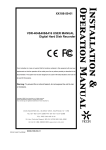
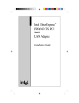
1
Fasep 2000 srl
Videotronic V653.G2: User’s Manual
Rev. 1.0
21 march, 2008
VIDEOTRONIC V653.G2
USER’S MANUAL
www.fasep.it
[email protected]
For any information, please contact:
e-mail:
FASEP 2000 srl
Via Faentina 96
50030 Ronta (Fi) Italy
Tel. #39 055 840 3126
Fax #39 055 840 3354
i
Fasep 2000 srl
Videotronic V653.G2: User’s Manual
Rev. 1.0
21 march, 2008
WARNING
.This document contains information which is the property of FASEP 2000 rl and all rights are reserved. This manual shall not be
photocopied or reproduced in any way without the prior written consent of FASEP 2000 srl.
.FASEP 2000 srl reserves the right to revise products firmware, software or documentation without obligation to notify any person
or organization. The information contained in this document is subject to change without warning.
.Prior of the installation of the unit described in this manual, user should read this manual carefully to be instructed properly on
installation, use and maintenance of the unit.
.Failing to read this manual and operate accordingly may cause damage to the user or the unit.
.FASEP 2000 srl shall not be responsible for inconvenience, breakdown, accidents due to uncomplete knowledge of this manual
or uncomplete application of raccomendations described in this manual.
.FASP 2000 srl shall not be responsible for inconvenience, breakdown, accidents due to unauthorized modifications of the unit, use
of non-original or unauthorized accessories (see Accessories listing in this manual for a list of original accessories available for this
model).
.FASEP 2000 srl shall not be responsible for any inconvenience, breakdown, accidents caused directly or indirectly by not
qualified service. Service to any parts by not qualified persons will void warranty and will void any right of the owner of
the unit.
SYMBOLS AND CONVENTIONS
To speed the retrieval of main information and make easy to understand the instructions, this manual uses the following typing
conventions:
<NAME OF THE PUSH BUTTON>
Used to indicate name of push-buttons on the control panel.
DISPLAY
Used to indicate text or number visible on the displays on the control panel.
☺
ADVICES
Contain useful advices or solutions, evidence d with respect to the rest of the text.
NOTE
Notes contain important information, evidenced to the rest of the text.
WARNING
Warning messages appears corresponding to procedures that, if not properly observed,
may lead to loose of data or cause damage to the unit.
!
CAUTION
Caution messages appears corresponding to procedures that, if not properly observed,
may cause injuries to the user.
ii
Fasep 2000 srl
Videotronic V653.G2: User’s Manual
Rev. 1.0
21 march, 2008
TABLE OF CONTENTS
WARNING . . . . . . . . . . . . . . . . . . . . . . . . . . . . . . . . . . . . . . . . . . . . . . . . . . . . . . . . . . . . . . . . . . . . . . . . . . . . . . . . . . . . . . . . . . ii
SYMBOLS AND CONVENTIONS . . . . . . . . . . . . . . . . . . . . . . . . . . . . . . . . . . . . . . . . . . . . . . . . . . . . . . . . . . . . . . . . . . . . . . . . ii
1
PRESENTATION . . . . . . . . . . . . . . . . . . . . . . . . . . . . . . . . . . . . . . . . . . . . . . . . . . . . . . . . . . . . . . . . . . . . . . . . . . . . 1-1
1.0
Intended Use . . . . . . . . . . . . . . . . . . . . . . . . . . . . . . . . . . . . . . . . . . . . . . . . . . . . . . . . . . . . . . . . . . . . . . . 1-1
1.1
Definitions . . . . . . . . . . . . . . . . . . . . . . . . . . . . . . . . . . . . . . . . . . . . . . . . . . . . . . . . . . . . . . . . . . . . . . . . . 1-1
2
INSTALLATION . . . . . . . . . . . . . . . . . . . . . . . . . . . . . . . . . . . . . . . . . . . . . . . . . . . . . . . . . . . . . . . . . . . . . . . . . . . . . 2-1
2.1
Moving the unit . . . . . . . . . . . . . . . . . . . . . . . . . . . . . . . . . . . . . . . . . . . . . . . . . . . . . . . . . . . . . . . . . . . . . . 2-1
2.2
Assembling the unit . . . . . . . . . . . . . . . . . . . . . . . . . . . . . . . . . . . . . . . . . . . . . . . . . . . . . . . . . . . . . . . . . . 2-1
2.3
Installation . . . . . . . . . . . . . . . . . . . . . . . . . . . . . . . . . . . . . . . . . . . . . . . . . . . . . . . . . . . . . . . . . . . . . . . . . 2-1
2.4
Electrical Hookup . . . . . . . . . . . . . . . . . . . . . . . . . . . . . . . . . . . . . . . . . . . . . . . . . . . . . . . . . . . . . . . . . . . . 2-1
2.5
Compressed air Hookup (PL models only) . . . . . . . . . . . . . . . . . . . . . . . . . . . . . . . . . . . . . . . . . . . . . . . . 2-1
3
USE OF CONTROL PANEL . . . . . . . . . . . . . . . . . . . . . . . . . . . . . . . . . . . . . . . . . . . . . . . . . . . . . . . . . . . . . . . . . . . . 2-2
3.1
Meaning of the icons on the screen . . . . . . . . . . . . . . . . . . . . . . . . . . . . . . . . . . . . . . . . . . . . . . . . . . . . . . 2-2
3.2
Meaning of the command keys . . . . . . . . . . . . . . . . . . . . . . . . . . . . . . . . . . . . . . . . . . . . . . . . . . . . . . . . . 3-1
4
CALIBRATION OF WHEEL BALANCER . . . . . . . . . . . . . . . . . . . . . . . . . . . . . . . . . . . . . . . . . . . . . . . . . . . . . . . . . . 3-1
4.1
How to calibrate the wheel balancer . . . . . . . . . . . . . . . . . . . . . . . . . . . . . . . . . . . . . . . . . . . . . . . . . . . . . 3-1
4.2
How to control the calibration of wheel balancer and position weight . . . . . . . . . . . . . . . . . . . . . . . . . . . . 3-2
5
Calibration ALU-SE . . . . . . . . . . . . . . . . . . . . . . . . . . . . . . . . . . . . . . . . . . . . . . . . . . . . . . . . . . . . . . . . . . . . . . . . . . 4-1
6
Calibration SME . . . . . . . . . . . . . . . . . . . . . . . . . . . . . . . . . . . . . . . . . . . . . . . . . . . . . . . . . . . . . . . . . . . . . . . . . . . . . 4-2
7
MEASUREMENT AND CORRECTION OF UMBALANCE . . . . . . . . . . . . . . . . . . . . . . . . . . . . . . . . . . . . . . . . . . . . 4-3
7.1
Placing the wheel rim on the wheel balancer . . . . . . . . . . . . . . . . . . . . . . . . . . . . . . . . . . . . . . . . . . . . . . . 4-3
7.2
Input of Rim Dimensions (external measuring system version) . . . . . . . . . . . . . . . . . . . . . . . . . . . . . . . . . 4-3
7.3
Input of Rim Dimensions (ALU-SE or LASER version) . . . . . . . . . . . . . . . . . . . . . . . . . . . . . . . . . . . . . . . 4-4
7.4
Detecting and correcting umbalance . . . . . . . . . . . . . . . . . . . . . . . . . . . . . . . . . . . . . . . . . . . . . . . . . . . . . 4-4
7.5
How to apply the weight using ALU-SE applicator . . . . . . . . . . . . . . . . . . . . . . . . . . . . . . . . . . . . . . . . . . . 4-5
7.6
How to apply the weight using LASER . . . . . . . . . . . . . . . . . . . . . . . . . . . . . . . . . . . . . . . . . . . . . . . . . . . . 4-5
8
HOW TO OPTIMIZE UNBALANCE OF THE WHEEL . . . . . . . . . . . . . . . . . . . . . . . . . . . . . . . . . . . . . . . . . . . . . . . . 5-1
9
SPECIAL FUNCTIONS . . . . . . . . . . . . . . . . . . . . . . . . . . . . . . . . . . . . . . . . . . . . . . . . . . . . . . . . . . . . . . . . . . . . . . . 6-1
9.1
Language selection . . . . . . . . . . . . . . . . . . . . . . . . . . . . . . . . . . . . . . . . . . . . . . . . . . . . . . . . . . . . . . . . . . 6-1
9.2
Setup . . . . . . . . . . . . . . . . . . . . . . . . . . . . . . . . . . . . . . . . . . . . . . . . . . . . . . . . . . . . . . . . . . . . . . . . . . . . . 6-1
9.3
Personalization . . . . . . . . . . . . . . . . . . . . . . . . . . . . . . . . . . . . . . . . . . . . . . . . . . . . . . . . . . . . . . . . . . . . . 6-1
9.4
Run-out check program . . . . . . . . . . . . . . . . . . . . . . . . . . . . . . . . . . . . . . . . . . . . . . . . . . . . . . . . . . . . . . . 6-1
APPENDIX . . . . . . . . . . . . . . . . . . . . . . . . . . . . . . . . . . . . . . . . . . . . . . . . . . . . . . . . . . . . . . . . . . . . . . . . . . . . . . . . . . . . . . . . A-2
A:
Technical data . . . . . . . . . . . . . . . . . . . . . . . . . . . . . . . . . . . . . . . . . . . . . . . . . . . . . . . . . . . . . . . . . . . . . A-2
B:
Environmental Data, Safety Features and Requirements . . . . . . . . . . . . . . . . . . . . . . . . . . . . . . . . . . . . B-1
iii
Fasep 2000 srl
Videotronic V653.G2: User’s Manual
Rev. 1.0
21 march, 2008
1
PRESENTATION
1.0
Intended Use
This unit is designed to measure and correct static and dynamic unbalance of vehicle wheel, the dimension and weight
of which are within the working range of the machine (see “Technical Data”appendix for reference)
This unit is meant for a professional use. Operator shall be properly trained before use. Training Course is not included
in the price of the unit and must be purchased separately.
This unit is designed for indoor use only (see “Environmental Data”appendix for reference).
!
CAUTION:
1.1
Definitions
This unit is designed to spin vehicle wheels only, within the range of dimensions and weight
approved (see “Technical Data”appendix for reference). Special adaptors suit this purpose. Do not
attempt to use the machine to spin anything else. Unproper locking may cause the part being
spinned to be ejected, causing damage to the unit itself, the operator or anything in the in the
neighboorhood.
1. Monitor
2. Back-mounted weight-compartments
3. Weights and tools trays
4. Interface icons + buttons
5. Side flange-holders
6. Wheel guard
7. EMS External Measuring system
8. Quick lock + HD shaft
9. Lower wheel guard
10. Tilt-system
11. Foot-pedal electro-magnetic brake
1-1
Fasep 2000 srl
Videotronic V653.G2: User’s Manual
2
INSTALLATION
2.1
Moving the unit
WARNING
Rev. 1.0
21 march, 2008
When the unit has to be moved: never lift
balancer by motor shaft or by neighborhood of it.
2.2
Assembling the unit
For ease of transportation, the wheel balancer might be disassembled
into units. If necessary, assembling instruction are provided within
each package..
2.3
Installation
The wheel balancer must be installed on a firm and level ground.
NOTE:
the machine must be secured to the floor. Using four holes
in the base and anchor bolts provided
2.4
Electrical Hookup
!
CAUTION:
2.4.1
Electrical hookup is to be provided by a qualified electrician.
2.4.2
A fusible wall-mounted switchbox is required at the installation site. This switch should provide on-off control and overload
protection for your wheel balancer only. The switchbox should be fused with time-delay fuse(s) in accordance with the
power rating specified on your wheel balancer.
2.4.3
Electrical connection of the machine should be by plug connectors.
2.4.4
The balancer must be effectively connected to ground. The electric cord is regularly provided with a ground terminal.
2.4.5
Make sure that Power Rate Specifications for your wheel balancer (refer to nameplate on the wheel balancer) comply
with those provided by the external power source.
Failure to follow these instructions can results in
damage to unit or create an electrical hazard and
will void warranty..
!
CAUTION
2.5
Compressed air Hookup (PL models only)
!
CAUTION
1.
2.
3.
2.5.1
After electrical hookup has been performed unit is ready to operate. Always observe pertinent safety
precautions when operating the unit (see Appendix tables for an overview of relevant Safety
requirement).
Failure to follow these instructions can result in damage to unit or create a hazard and will void
warranty.
Compressed Air hookup is to be provided by a qualified technician, under the local safety
requirements, in line with relevant national standards and regulations. All fitting and hoses must
conform to local codes.
A wall-mounted lubricator and water-separator is required at the installation site.
Compressed Air circuit to the balancer shall be regulated to a maximum pressure of 7 atm.
Overpressure could compromise cylinder operation.
CONNECT TO AIR SUPPLY:
The machine is fitted with a universal connector and therefore no other special or additional fitting is required. Push all
the way onto the connector a high pressure rubber air-hose and secure it.
2-1
Fasep 2000 srl
Videotronic V653.G2: User’s Manual
3
Rev. 1.0
21 march, 2008
USE OF CONTROL PANEL
Fig. 5 Panel V653
3.1
Meaning of the icons on the screen
Delete last character in input
activation code
Fig. 9
Fig. 6
APS Function
Change selection
Fig. 10
Fig. 7
Calibration
Set default values
Fig. 11
Fig. 8
Select balancing mode
2-2
Fasep 2000 srl
Videotronic V653.G2: User’s Manual
Rev. 1.0
21 march, 2008
Diagnostic
Laser calibration
Fig. 12
Fig. 19
Key down
Put in the rod laser in rest
position
Fig. 13
Fig. 20
Position calibration
Start laser
Fig. 14
Fig. 21
Go to previous page
Extract fully rod laser
Fig. 15
Fig. 22
Manul input measures
Fine resolution
Fig. 23
Fig. 16
Set Dynamic/Static
Access to Information center
Fig. 24
Fig. 17
Mode moto
Access to page measures
Fig. 25
Fig. 18
2-3
Fasep 2000 srl
Videotronic V653.G2: User’s Manual
Rev. 1.0
21 march, 2008
Key SET/OK
Set measures
Fig. 26
Fig. 33
Double operator
Go to setup menù
Fig. 27
Fig. 34
Optimize
Skip current operation
Fig. 28
Fig. 35
Restart software
Split function
Fig. 29
Fig. 36
Reset partial statistics
Stop turning wheel
Fig. 30
Fig. 37
Reset variation in page Sensor
Key up
Fig. 31
Fig. 38
Save
View menù and selection
(UP/DOWN
Fig. 32
Fig. 39
Automatic flange calibration
Fig. 40
2-4
Fasep 2000 srl
Videotronic V653.G2: User’s Manual
3.2
Rev. 1.0
21 march, 2008
Meaning of the command keys
Disable open pneumatic lock (safety for flange use)
Fig. 41
Open / close pneumatic lock
Fig. 42
Tilting
Fig. 43
Open / close wheel guard
Fig. 44
2-5
Fasep 2000 srl
Videotronic V653.G2: User’s Manual
Rev. 1.0
21 march, 2008
4
CALIBRATION OF WHEEL BALANCER
4.1
How to calibrate the wheel balancer
NOTE:
the following symptoms indicate need for calibration::
a) check calibration program fails.
c) indicated point of unbalance constantly wrong
b) constant low or high weight readings.
d) more than 2 spins required to balance wheels
repeatedly.
Switch on the wheel balancer.
Select SET UP > CALIBRATION > SET/OK >
CALIBRATION > SET/OK.
Fig. 45
Spin with no wheel on shaft (Fig. 46)
Close the wheel guard or press <START>.
Fig. 46
At the end of the spin, put a wheel (Fig. 47)
and close the wheel guard or press <START>.
Fig. 47
At the end of the spin, put the calibration
weight (Fig. 48) and close the wheel guard or
press <START>.
Fig. 48
3-1
Fasep 2000 srl
Videotronic V653.G2: User’s Manual
4.2
Rev. 1.0
21 march, 2008
How to control the calibration of wheel balancer and position weight
Switch on the wheel balancer.
Select SET UP > CALIBRATION > SET/OK >
CHECK CALIBRATION > SET/OK.
Fig. 49
Put a wheel on the shaft and press <START>
(Fig50).
Fig. 50
Put the calibration weight (Fig.51) and press
<SET/OK>.
Close the wheel guard or press <START>.
At the end of the spin, 160-0 will show on the
video (tolerance allowed is ±10).
Fig. 51
Put the weight at 6h o’clock: the weight
indicators of internal side must be both green.
If not, press <6h>.
Put the weight at 6h o’clock and press <SET
OK>.
Fig. 52
3-2
Fasep 2000 srl
Videotronic V653.G2: User’s Manual
5
Rev. 1.0
21 march, 2008
Calibration ALU-SE
Switch on the wheel balancer.
MAIN MENU > MENU > RESET > CALIB >
CALIBRATION > SET/OK (fig. 53).
ALU-SE
Put the rod on rest position (fig.53) and press SET/ OK.
Fig. 53
Put the rod on the flange (fig.54) and press SET/ OK.
Select width of wheel
Put the rod on internal side of the rim (fig.55) and press
SET/OK.
Fig. 54
Press <ESC> to go back to standard use.
Fig. 55
4-1
Fasep 2000 srl
Videotronic V653.G2: User’s Manual
6
Rev. 1.0
21 march, 2008
Calibration SME
Switch on the wheel balancer.
MAIN MENU > MENU > RESET > CALIB > SME
CALIBRATION > SET/OK (fig. 56)
Put the rod on rest position (fig. 56) and press SET/ OK.
Fig. 56
Put the rod (fig. 57) and press SET/OK.
Press <ESC> to go back to standard use.
Fig. 57
4-2
Fasep 2000 srl
Videotronic V653.G2: User’s Manual
Rev. 1.0
21 march, 2008
7
MEASUREMENT AND CORRECTION OF UMBALANCE
7.1
Placing the wheel rim on the wheel balancer
7.1.1
Select the cone or flange suitable for the wheel to be balanced. Specific mounting instructions are delivered with each
flange
NOTE:
the operation of centering and tightening of the wheel on the flanges is of basic importance for correct
balancing. Good results depend on proper performance of these procedures.
To accurately clean up the superficial ones of connection before whichever operation.
!
7.2
CAUTION:
Always make sure flanges are correctly locked on the motor shaft and wheel is correctly locked on
the flange being used.
Input of Rim Dimensions (external measuring system version)
for V65x, V64x, V55x-D (automatic input of all data)
MAIN MENU > INPUT
Insert the distance (fig.59).
Insert the width (fig.60).
Fig. 59: Distance
Fig. 60: Width
4-3
Fasep 2000 srl
Videotronic V653.G2: User’s Manual
7.3
Rev. 1.0
21 march, 2008
Input of Rim Dimensions (ALU-SE or LASER version)
MAIN MENU > INPUT
Press ALU MODE untill the required position of weight is on the video (fig.61).
Insert the distance (IN1).
Insert the distance (IN2).
Fig. 61
Press ALU MODE untill the required position of weight is on the video (fig.61).
Insert the distance (IN1).
Insert the distance (IN2).
Fig. 62
7.4
Detecting and correcting umbalance
7.4.1
After setting wheel dimensions, press <START> or close the safety cover to spin the wheel and start the measurement
run.
!
CAUTION:
wheel start automatically when safety cover is closed.
7.4.2
At the end of the spin the wheel will brake automatically and the display will show the weight position and weight
requirement to correct the wheel’s umbalance.
7.4.3
Apply the weights (fig.63, fig.64). If umbalance shown is 0, press <FINE> to show residual umbalance.
Fig. 63
Fig. 64
4-4
Fasep 2000 srl
Videotronic V653.G2: User’s Manual
7.5
Rev. 1.0
21 march, 2008
How to apply the weight using ALU-SE applicator
Place the weight as in the picture 66.
Turn the wheel until reach the application
position of the weight (fig. 65).
Move the rod until reach the application
position of the weight (fig. 66).
Apply the weight (fig. 67).
Fig. 65
Repeat the procedure for the other side.
.
Fig. 66
Fig. 67
7.6
How to apply the weight using LASER
Turn the wheel until the position weight
indicators of one side are both green (fig. 68).
The laser come out to show the point of
application of the weight (fig. 69).
Apply the weight on the laser dot.
Repeat the procedure for the other side.
Fig. 68
Fig. 69
4-5
Fasep 2000 srl
Videotronic V653.G2: User’s Manual
Rev. 1.0
21 march, 2008
8
HOW TO OPTIMIZE UNBALANCE OF THE WHEEL
8.1.1
MAIN MENU > OPTIMIZE
Measure the unbalance of the rim only ( fig. 70).
Fig. 70 first spin, rim only
Mount the tire on the rim and put the wheel on the shaft
(fig.71).
Spin the wheel
Select the optimization and follow the video instruction.
Fig. 71 second spin, complete wheel
WARNING:
NOTE:
Balancing with flanges, put the accessories assembled to the rim during the complete operations.
Selection of optimization: the green solution is the advised from the machine. The user can be choose also
one of the other.
5-1
Fasep 2000 srl
Videotronic V653.G2: User’s Manual
Rev. 1.0
21 march, 2008
9
SPECIAL FUNCTIONS
9.1
Language selection
9.1.1
9.1.2
MAIN MENU >SET UP > USER SET UP > LANGUAGE > SET OK >.
Select the language and press SET OK.
9.2
Setup
9.2.1
MAIN MENU >SET UP > USER SET UP .
9.2.2
Select item and press SET OK.
9.3
Personalization
9.3.1
MAIN MENU > PERSONAL.
9.3.2
Follow the instruction on video to insert the personalization.
9.3.3
Press SAVE to memorize.
9.4
Run-out check program
9.4.1
Insert the wheel dimensions.
9.4.2
MENU > RUNOUT.
9.4.3
Put the rod (fig. 72) and turn slowly the wheel for 360/.
Fig. 72 Runout
6-1
Fasep 2000 srl
Videotronic V653.G2: User’s Manual
Rev. 1.0
21 march, 2008
APPENDIX
A:
Technical data
Power requirement
400W
Speed Balancing
98RPM
Measuring time
4-15 s.
Accuracy
±1grammo (±1/28 once)
Wheel Dimensions
Diameter Rim diameter
Rim Width (with wheel-guard)
Wheel Weight
Wheel balancer dimensions
V653
Fig. 73: Measures
L (mm)
1120
L1 (mm)
500
L2 (mm)
1230
P (mm)
1030
P1 (mm)
200
P2 (mm)
1450
H (mm)
1390
H1 (mm)
1440
Peso (kg)
167
A-2
8" (200 mm) - 26" (650 mm)
max 16" (415mm)
max 90 Kg (198Lbs)
Fasep 2000 srl
Videotronic V653.G2: User’s Manual
B:
Rev. 1.0
21 march, 2008
Environmental Data, Safety Features and Requirements
Environmental Data
[Operating conditions]
This unit is designed for indoor use only.
Temperature:
0 to 45/C
Relative Humidity: 5 to 80% a 40/
[Storage conditions]
Package is designed for indoor storage only.
Temperature:
-25/ to 70/C
Relative humidity: 5 at 95% to40/C
1.
2.
!
Safety Features
The Balance Weights Holder may be removed for servicing. It is secured to the machine body through screws so that only
voluntarily it may be removed. Removal of this protection is therefore restricted to Authorized Service Engineers.
The Control Panel may be removed for servicing. It is secured to the machine body through screws so that only voluntarily
it may be removed. Removal of this protection is therefore restricted to Authorized Service Engineers.
CAUTION:
The safety cover is anyway required when using the motorcycle adapter.
WARNING
FASEP 2000 srl shall not be responsible for any inconvenience, breakdown, accidents caused
directly or indirectly by unauthorized service. Service to any parts by unauthorized engineers will void
warranty and will any right of the owner of the unit..
NOTE:
As this unit runs at speed below 100rpm, a safety cover is not required. However a safety cover is
recomended when balancing wheels with diameter bigger then 20".
1.
2.
3.
4.
5.
6.
7.
8.
9.
10.
General Safety Requirement
[before using/servicing this unit]
Read this instruction sheet and the whole user’s manual before operating or servicing the wheel balancer.
Make sure electrical power source conforms to requirements shown on nameplate (see also model identification chart
for reference).
Make sure the unit has a stable position.
[when using the unit]
Protect power leading to the unit from damage.
When work area is being washed, make sure unit is adequately protected.
Remove all stones and mud lodged in tire treads before balancing the wheel.
Do not touch spinning wheel. Always use Safety Safety cover to be protected.
Make sure counterweights are securely attached before checking residual umbalance.
[when servicing the unit]
Make sure power sources are disconnected before service on the unit is performed.
Service to PCB, electrical and mechanical parts should be done only by an Authorized FASEP 2000 Service Center.
B-1
Fasep 2000 srl
Videotronic V653.G2: User’s Manual
Rev. 1.0
21 march, 2008
Safety Features of the Wheel Balancer
This product was designed and built according to the current European Safety regulation (CE). Several protective devices are
installed on the machine along with indications of danger.
Fig. 74 Protective devices
The wheel balancer is equipped with the following safety devices:
A.
B.
C.
D.
E.
F.
G.
H.
I.
J.
K.
L.
Protective wheel-guard: electrically interlocked to the machine, it prevents dangerous ejection of parts from the wheels
under examination, delineating the work area to avoid contact with parts in rotation.
Protective covers: protect access to electrical, mechanical and pneumatic parts of the machine.
Plug-socket combination: for the cutting of power supply.
Electric Power Switch yellow / red padlock: functions as emergency stop.
Quick connection to air pipe: allows the detachment from the air.
Filter-regulator: regulates the air pressure input to avoid overpressure inside the pneumatic system of the wheel balancer
Pressure gauge: prevent the operation of the machine in cause of insufficient air pressure.
One-way valve: maintain pressure in the pneumatic circuit, prevents unwanted movements due to powering of machines.
Closed-center valve: operating an emergency or following a power failure stops the movement of tilting-system.
Beep sound related to the movement of protective wheel-guard: after the operator had pressed the button for close the
wheel-guard, the beep sound warning of the imminent closing movement and end the cycle of balancing warns of the
movement for opening.
Command button Safety lock: when it is active (light green on) does not allow the pneumatic lock to operate.
B-2
Fasep 2000 srl
Videotronic V653.G2: User’s Manual
Rev. 1.0
21 march, 2008
There are aslo labels and pictograms laws for the display of residual risks.
Fig. 75 Labels applied to wheel balancer
List of labels applied to wheel balancer:
2M2668
Label “Info Fasep”
2M2247
“Serial number”
9M2477
“Should Use gloves”
9M2476
“Danger high voltage”
2M2494-1
“Maximum operating pressure”
9M2517
“Warning danger”
9M3012
“Tape yellow/black”
2M2493
“Danger of crushing”
2M1632
“Specific power”
2M2323
“Parking brake”
In case of poor readability or damaged plates applied to the machine, the user must order the
missing label, using the codes mentioned, and must reposition it in the same place as the
existing one.
The safe use of this product is subject to the limitations technical "Technical Features" and
“Environmental Features” listed in Appendix B
B-3