1
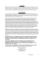
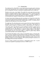
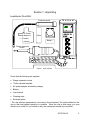
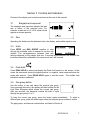
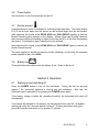
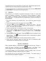
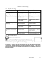
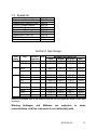
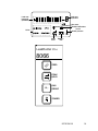
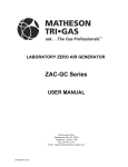
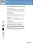
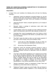
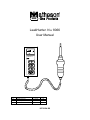
LeakHunter Plus 8066
User Manual
LeakHunter Plus
LTR
A1
B1
REVISION
Release for Prod
Revise Spares List
DATE
11-02-95
05-23-96
BY
CJC
BT
INT-0124-XX
DISCLAIMER
Matheson Gas Products makes no representations or warranties with respect to the contents or use of
this manual and specifically disclaims any express or implied warranties of merchantability or fitness for
any particular purpose. Further Matheson reserves the right to make changes to the instrument and this
manual, at any time, without obligation to notify any person or entity of such revisions or changes.
LIMITED WARRANTY
This equipment is sold by Matheson Gas Products (Matheson) under the warranties set forth in the
following paragraphs. Such warranties are extended only with respect to the purchase of this equipment
directly from Matheson or Matheson's Authorized Agent as new merchandise and are extended to the
first Buyer thereof other for than the purpose of resale.
For a period of one year from date of original delivery (ninety days in corrosive service) to Buyer or to
Buyer's order, this equipment, is warranted to be free from functional defects in materials and
workmanship and to conform to the description of this equipment contained in this manual and any
accompanying labels and/or inserts, provided that this equipment is properly operated under the
conditions of normal use and that regular and periodic maintenance and service is performed or replacements are made in accordance with the instructions provided. Expendable parts of this equipment are
similarly warranted to be free from functional defects in materials and workmanship and to conform to the
description of this equipment contained in this manual and any accompanying labels and/or inserts. The
foregoing warranties shall not apply if the equipment has been repaired other than by Matheson or a
service facility designated by Matheson, or if this equipment has not been operated and maintained in
accordance with written instructions provided by Matheson, or has been altered by anyone other than
Matheson, or if the equipment has been subject to abuse, misuse, negligence or accident.
Matheson's sole and exclusive obligation and the Buyer's sole and exclusive remedy under the above
warranties is limited to repairing or replacing, free of charge, at Matheson's sole discretion, the equipment
or part which is telephonically reported to be a problem to the local Matheson Branch Location, and which
if so advised, is returned with a written statement of the observed deficiency, not later than seven days
after the expiration of the applicable warranty, to the Matheson Gas Equipment Technology Center during
normal business hours, transportation charges prepaid, and which, upon examination, is found to comply
with the above warranties. Return trip transportation charges for the equipment or part shall be paid by
the Buyer.
MATHESON SHALL NOT BE OTHERWISE LIABLE FOR ANY DAMAGES INCLUDING BUT NOT
LIMITED TO INCIDENTAL DAMAGES, CONSEQUENTIAL DAMAGES, OR SPECIAL DAMAGES,
WHETHER SUCH DAMAGES RESULT FROM NEGLIGENCE, BREACH OF WARRANTY OR
OTHERWISE.
THERE ARE NO EXPRESS OR IMPLIED WARRANTIES WHICH EXTEND BEYOND THE
WARRANTIES HEREINABOVE SET FORTH. MATHESON MAKES NO WARRANTY OF
MERCHANTABILITY OR FITNESS FOR A PARTICULAR PURPOSE WITH RESPECT TO THE
EQUIPMENT OR PARTS THEREOF.
ACCEPTANCE OF THE EQUIPMENT BY THE FINAL BUYER INDICATES THE FINAL BUYER'S
ACCEPTANCE OF ALL WARRANTIES AND LIMITATIONS SET FORTH ABOVE.
Matheson Gas Products
166 Keystone Drive
Montgomeryville, PA 18936
Ph. 215-641-2700
Fax 215-641-2714
INT-0124-XX
2
1.0 Introduction
The LeakHunter Plus, Model 8066, is a hand held instrument typically used for detecting
leaks in gas plumbing joints, and for testing the integrity of sealed units using a tracer
gas. The magnitude of the leak is indicated by a bargraph display and an audible tick.
Operation can be one, or two handed. The audible tick and a peak hold mode allows
operation in awkward situations where the display is not visible. The peak hold mode
causes the display to retain the highest reading detected. A nozzle is available for
measuring large leaks by allowing the sample to be thirty times greater than with it off.
An extended probe is supplied to facilitate access in difficult applications.
An internal pump draws leakage gas and surrounding air in through the nozzle, then
over the sensor that measures the thermal conductivity of the gas/air mixture. Thermal
conductivity is defined as the rate of flow of heat through a medium. The gas/air mixture
escapes from the instrument via four holes in its base.
The LeakHunter Plus will indicate when a gas is present that has a thermal conductivity
that differs from that of the ambient air on which it was zeroed. The instrument is
normally zeroed in ambient air comprising a mixture of approximately 78% nitrogen and
21% oxygen. Hence, the instrument is not very sensitive to nitrogen or oxygen, but has
a high sensitivity to helium and hydrogen since these have very different thermal
conductivities from air. (See Section 8.) A gas may have a higher or lower thermal
conductivity than air, and thus produce a positive or negative reading on the display.
The instrument has four gas group ranges to target the gases having thermal
conductivities that differ from air by different degrees.
The instrument can indicate a leak in terms of concentration (ppm), or flow rate (cfm,
ml/sec or ml/min). Readings are approximateand relative; the instrument is intended to
aid in the precise location of a leak, and to give an indication of its severity. Flow rate
readings assume that all the leaking gas passes through the probe: If some of the
leaking gas escapes to the surrounding air, without passing through the instrument, the
flow reading will be inaccurate to that extent.
The unit is battery operated using standard or rechargeable battery cells. A power
transformer is supplied for operating the unit from a 120VAC source.
INT-0124-XX
3
Section 1 Unpacking
LeakHunter Plus 8066
Extended probe
AC Power
adaptor &
Cable
battery
charger
Probe Clip
Battery
Range extension
nozzle
Figure 1 case contents
Check that the following are supplied:
•
Range extension nozzle
•
*Probe clip and template
•
AC power adapter and battery charger
•
Battery
•
User manual
•
Cleaning wipe
•
Extended probe
* The clip attaches permanently to the rear of the instrument. The probe slides into the
clip so that one-handed operation is possible. Since the clip is quite large, you may
decide not to install it if you intend to carry the instrument around in your pocket.
INT-0124-XX
4
1.1
Attaching the probe clip
A template is supplied to permit accurate positioning of the clip. Note that the adhesive
on the clip is permanent, and once fitted, the clip is not easily removed.
1. Clean the rear of the box using the wipe supplied. Allow the surface to dry.
2. Position the template onto the rear of the instrument as shown in Figure 1.
3. Peel off the paper that protects the adhesive on the back of the clip.
Rear of
case
Probe
clip
Assembly
aid
Figure 2 Probe clip template
4. Carefully position the clip in the position defined by the template and press it firmly in
position.
5. Remove the template.
6. The probe can now be clipped to the instrument for one-handed operation. Pass the
cable through the slot in the clip, then push the probe into the clip until it clicks into
place.
7. To remove the probe, simply pull it forward out of the clip.
INT-0124-XX
5
Section 2 Specification
Maximum sensitivity
under ideal conditions
He 1x10⁻⁵, R12 8x10⁻⁵, CH4 1x10⁻⁴, C02 1x10⁻⁴ (ml/s)
Detector
Dual cell micro volume thermal conductivity cell
Detects
All gases with a thermal conductivity different from air
Display units
cm3/s, cm3/min, cu ft/min, ppm - selectable
Functions
Peak hold, Zero, Calibrate, Gas type, nozzle type
Response time
Approximately 1s
Recovery time
Approximately 1s
Audio
Signal proportional to leak rate.
Diagnostics
Battery low indication Detector cell failure alarm
Operating time
4 hours maximum from rechargeable battery
Battery
One PP3 dry cell or rechargeable
Mains supply
115V 50/60 Hz
Carrying case size
3.5 x 10 x 14 (inches) (8.9 x 25.4 x 35.6 cm)
Weight:
Hand unit
Total, inc. case
440 g (1 lb)
1.5 kg (3.3 lb)
INT-0124-XX
6
Section 3 Controls and Indicators
Pictures of the display and controls are shown at the rear of this manual.
3.1
Bargraph and exponent
The bargraph and exponent indicate the leak
rate in terms of the selected units. For
example, a leak rate of +6 x10⁻⁴ ml/sec would
appear as shown opposite.
3.2
Zero
Operating this button sets the detected value, the display, and audible signal to zero.
3.3
Units
Press ZERO and GAS GROUP together to step
through the available units of measure to set the one
desired. The correspondence between leak rate
settings depends on the sample flow rate. If accurate measurements are required the
instrument should be calibrated in the same mode as it will be used.
3.4
Peak hold
Press PEAK HOLD to select and display the Peak Hold symbol on the screen. In this
mode, the instrument shows the highest positive, or negative, value measured since the
mode was entered. Press PEAK HOLD again to exit this mode. The audible leak
indication remains unaffected.
3.5
Gas group button
Use this button to see and select the required gas group.
Upon pressing the button, the display will blank except for the
Leak Rate Exponent which shows the current gas group.
After two seconds, the displayed number will start to cycle
through the gas groups 1 to 4.
To keep the current gas group, press the button again immediately. To select a
different gas group, press the button again when the required group number is visible.
The gas groups, and thermal conductivities, are listed in Section 8.
INT-0124-XX
7
3.6
Power button
Use this button to turn the instrument on and off.
3.7
Nozzle present
A range extension nozzle is available for monitoring high leak rates. The nozzle diverts
97% of the air input away from the sensor so that a much larger flow can be handled.
After attaching the nozzle, press PEAK HOLD and GAS GROUP together so that the
Nozzle Present symbol appears on the display. Where a flow rate is being indicated,
the instrument adjusts the reading to adjust for the fact that 97% of the flow is bypassing
the sensor. Concentration (ppm) values will not be affected.
Upon removing the nozzle, press PEAK HOLD and GAS GROUP again to remove the
Nozzle Present symbol.
The same operations should be carried out when attaching, or removing, the extended
probe supplied as part of the 8066.
3.8
Battery low
This symbol becomes visible when the battery is low. Refer to Section 6.
Section 4 Operation
4.1
Starting up and switching off
Press the POWER button to turn on the instrument. During the first six seconds
(approx.), the instrument performs a start-up and test sequence. After this, the
instrument can be switched off by pressing the POWER button again.
If the battery voltage is below the operating threshold, the instrument will switch off
automatically.
If no buttons are pressed for 15 minutes, the instrument will turn itself off. An audible
warning will occur for 5 seconds before it turns off. Pressing any button during this
period will keep the instrument on for another 15 minutes.
INT-0124-XX
8
4.2 Measurement
To use the instrument:
1. If necessary, press ZERO and GAS GROUP repeatedly to select the required units.
See Section 3.3.
2. Use GAS GROUP to check/select the appropriate gas group. See Sections 3.5 and
8.
3. Press ZERO to zero the meter reading on the instrument, well away from the leak.
4. Use the instrument to trace the leak. The bargraph display and exponent, along with
the audible ticks, indicate the extent of the leak.
For awkward situations, the instrument can be used one-handed with peak hold
selected. See Section 3.4.
4.3
Sensitivity setting
To contend with various leak rates, the instrument has three decade ranges: 1, 10 and
100. This is particularly pertinent to the audible ticks: The dynamic range of the audible
ticks is only 100:1, and will saturate in the presence of high gas concentrations unless
the sensitivity is reduced.
At switch-on, or if the units are changed, the instrument defaults to the most sensitive
range.
To change the sensitivity range, press and hold ZERO then press PEAK HOLD. You
will see the displayed exponent change with the change of sensitivity. For instance,
with ml/sec units, successive exponents will be -5 (most sensitive range),-4 and -3, for a
zeroed reading. Press ZERO and PEAK HOLD again to select the desired sensitivity.
For flow measurements, you can use the x30 nozzle as an alternative to reducing the
sensitivity level. The x30 nozzle allows the instrument to cope with higher leakage flow
rates without reducing the dynamic range of the instrument.
4.4
x30 nozzle
This nozzle allows the measurement of flow rates with high volume leaks that are
beyond the normal range of the instrument. The nozzle diverts approximately 97% of
the gas/air mixture away from the sensor so that the instrument can handle
approximately 30 times the normal maximum leak rate. The instrument must be told
that the nozzle is installed so that leak rate readings are adjusted accordingly (i.e. 30
times the actual measured rate).
1. Attach the nozzle over the normal nozzle and locate it securely on the housing.
2.
Press the PEAK HOLD and GAS GROUP buttons together to make the Nozzle
Present symbol appear on the display.
INT-0124-XX
9
The extended probe has a similar effect to the x30 nozzle. Note that the response and
cleardown times are increased when the extended probe is fitted.
To restore the instrument to its normal state, remove the nozzle and press PEAK HOLD
and GAS GROUP to remove the Nozzle Present symbol.
4.5
Calibration
The instrument is not intended for accurate measurement of leaks; for normal leak
tracing, no calibration is necessary. The instrument is factory calibrated to a helium
leak. However, it is possible to improve the accuracy of the instrument for a particular
gas by calibrating it. You will need access to a standard leak, or known concentration of
the required gas.
1. Set up the instrument to the required state: units, nozzle (not) present and gas
group.
2. Present the instrument with a null sample (air) and press ZERO.
3. Hold down ZERO and press POWER briefly. Release both buttons. The units
indication on the display will flash to indicate that the instrument is in calibration
mode. The audible ticks are disabled.
4. Present a standard leak, or concentration of gas, to the instrument.
5. Set the display bargraph and exponent to read the standard leak flow rate or
concentration: use PEAK HOLD to increase the displayed value, or GAS GROUP
to reduce it.
6. Pressing ZERO will zero the display. Pressing POWER will set the calibration to the
general default. The
symbol will become visible to indicate that the general
default calibration is in use.
7. Press ZERO and POWER again to restore normal instrument operation.
8. Check that the instrument reads the correct flow rate or concentration when
presented with the standard leak rate or concentration.
Section 5 Batteries
Either a standard alkaline, or rechargeable Ni-Cad, battery may be used. Change, or
replace, the battery if the Battery Low symbol
appears on the display. If the
battery voltage falls to an unacceptable level the instrument will switch itself off.
To change the battery, turn off the instrument, remove the battery cover on the rear
cover, unplug the old battery, install the new one in its place.
The instrument will run from the battery or the AC adapter. The internal battery is
disconnected when the adapter is plugged in.
INT-0124-XX
10
The battery must be removed from the instrument for recharging;
recharged in the instrument.
it cannot be
Section 6 Accessories
6.1
AC power adapter and battery charger
The meter can be used with the ac power adapter without removing the battery. Plug
the smaller of the two female connectors on the adapter into the base of the meter.
Plugging in the adapter disconnects the internal battery.
The adapter is for indoor use only.
The battery charger is for indoor use with Ni-Cad batteries only. Do not attempt to
recharge other types of battery as damage or injury may result. Recharging time is 16
hours for a standard capacity battery and 19 hours for a high capacity battery.
Recharging a partially discharged battery can reduce its capacity.
6.2 Extended probe
Attaching the extended probe has the same effect on instrument sensitivity as fitting the
range x30 nozzle. With the extended probe attached, the instrument will take longer to
respond to a leak, and to clear down afterwards.
INT-0124-XX
11
Section 7 Servicing
7.1
Trouble shooting
Symptom
Probable Cause
Cure
Instrument lacks
sensitivity
Probe connection loose
on gun nozzle
Tighten coupling around
probe
Response time too long
Capillary inside probe
partially blocked
Replace probe, or clear it
with a fine wire
Probe connection loose
on gun nozzle
Tighten coupling around
probe
Large amounts of tracer
gas in atmosphere
Allow atmosphere to clear,
or move test site.
Probe connection loose
on gun nozzle
Tighten coupling around
probe
Depleted battery
Replace battery, or use AC
power adapter
Wrong connector used on
AC power adapter
Make sure smaller female
connector is used on unit.
Unstable reading on high
sensitivity
Instrument will not power
up
7.2 Error indications
Battery low. See Section 5.
Instrument calibration lost, and general calibration in use.
Recalibrate. See Section 4.5. At switch-on, this error is indicated by a
constant leak rate exponent digit 0 or 1 on the display.
In the event of a serious fault with the instrument, the leak rate exponent digit flashes.
The digit value indicates the nature of the fault for diagnostic purposes. There are no
feild repairs at this point. Call Customer Service (800-828-4313) to arrange return of the
instrument for repair.
INT-0124-XX
12
7.3 Spares list
Item
Replacement Standard Probe
Replacement Extension Probe
115V AC Charger Adapter
220V AC Charger
Replacement Capillary Tube
Replacement Battery Cover
Replacement Probe Clip
220V AC Adapter
User Manual
Part No.
8066-03
8066-04
8066-05
8066-06
8066-07
8066-08
8066-09
8066-10
8066-11
Section 8 Gas Groups
Gas
Gas
Relative
group
response
1
Hydrogen 295
Helium
240
Pol
+
+
Minimum detectable leak
ml/s
ml/min
cu ft/min
ppm
8.10E-06 4.9E-04
1.7E-08 1.3E+02
1.00E-05 6.0E-04
2.1E-08 1.6E+02
2
Neon
Xenon
41
41
+
-
5.80E-05
5.81E-05
3.5E-03
3.5E-03
1.2E-07
1.2E-07
9.3E+02
9.3E+02
3
R11
R12
R21
R22
35
30
30
25
-
6.84E-05
7.90E-05
7.98E-05
9.46E-05
4.1E-03
4.7E-03
4.8E-03
5.7E-03
1.5E-07
1.7E-07
1.7E-07
2.0E-07
1.0E+03
1.3E+03
1.3E+03
1.5E+03
4
Methane
Argon
CO2
Water
23
18
16
14
+
-
1.06E-04
1.37E-04
1.53E-04
1.75E-04
6.4E-03
8.2E-03
9.2E-03
1.1E-02
2.2E-07
2.9E-07
3.2E-07
3.7E-07
1.8E+03
2.2E+03
2.4E+03
2.8E+03
Minimum detectable leak is the smallest leak that the instrument will detect under ideal
conditions.
Warning: Hydrogen and Methane are explosive in
concentrations, and this instrument is not intrinsically safe.
INT-0124-XX
some
13
Leak rate
exponent
Leak rate
bargraph
(mantissa)
Not used
Default calibration
in use
Nozzle present
Units
Peak
hold
Battery
low
LeakHunter Plus
8066
ZERO
PEAK
HOLD
1,2,..
GAS
GROUP
POWER
INT-0124-XX
14