1
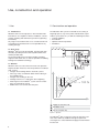
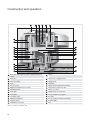
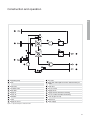
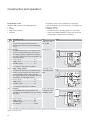
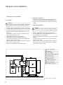
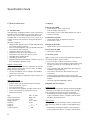
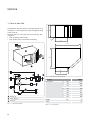
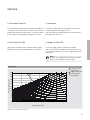
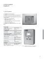
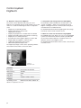
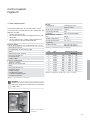
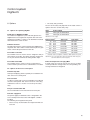
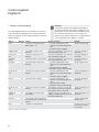
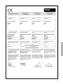
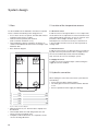
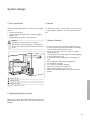
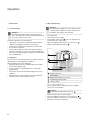
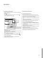
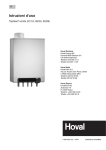
AdiaVent ®. Air recirculation unit for cooling closed spaces. Design Handbook AdiaVent® Design Handbook Subject to technical alterations. Art.Nr. 4 207 885 09 / 2008 © Hovalwerk AG, Liechtenstein, 2007 Safety A 3 AdiaVent® ADV B Air recirculation unit for cooling closed spaces 7 Options C 25 Control System D 29 E System Design 39 Operation F 43 Safety A 1 Symbols________________________________ 5 2 Operational safety_______________________ 5 3 Information for a user manual_____________ 5 4 A Safety 1 Symbols Caution This symbol warns against risks of injury. Please heed all instructions designated by this symbol to prevent injuries and/or death. Attention This symbol warns against risks of property damage. Please heed the respective instructions to prevent risk of damage to the unit and its functions. 3 Information for a user manual According to the accident prevention regulations of some countries, the operator of equipment must meet certain requirements for the prevention of occupational accidents and instruct the operating personnel as to the hazards that may occur and how to prevent them. This can be done with the help of the User Manual. In addition to national regulations for accident prevention and environmental protection, a user manual should also include the most important items of the operating instructions. Notice This symbol denotes information about the economic use of the equipment or special tips. 2 Operational safety AdiaVent® units are state of the art and safe to operate. Nevertheless, hazards may emanate from the units if they are used incorrectly or not used as intended. Therefore: • Please read the operating instructions before unpacking, installing, commissioning and before maintaining the equipment. • Store the operating instructions so that they are easily accessible. • Observe all appropriate informational and warning signs. • Rebuilding or making changes to the unit on one's own authority are not permitted. • Follow the local safety and accident prevention regulations at all times. • AdiaVent® units may be installed, operated and maintained only by trained and instructed specialists. Specialists as defined by these operating instructions are those persons who, based on their training, knowledge and experience as well as their knowledge of the relevant regulations and guidelines, can carry out the work assigned to them and recognize potential hazards. 5 6 AdiaVent® ADV Air recirculation unit for cooling closed spaces 1 Use____________________________________ 8 2 Construction and operation_______________ 8 3 Technical data__________________________ 13 4 Design example________________________ 18 5 Options_ ______________________________ 19 6 Control system_________________________ 19 7 Transport and installation________________ 20 8 Specification texts______________________ 22 9 Declaration of conformity________________ 24 B Use, construction and operation 1 Use 2 Construction and operation 1.1 Intended use AdiaVent® units are for high spaces. Also included under intended use are compliance with the installation, commissioning, operating and maintenance provisions (operating instructions). Any usage over and above this use is considered to be not as intended. The manufacturer is not responsible for any resulting damage. The AdiaVent® ADV system is intended for the cooling of large high spaces (e.g. factory halls, industrial halls, supermarkets, sport arenas etc.). It fulfils the following functions: • Cooling (adiabatic) • Recirculation • Optional: mixed air operation • Air filtration 1.2 User group AdiaVent® units may only be installed, operated and maintained by specialist personnel well acquainted with them and the possible risks. The design handbook is intended for English-speaking engineers and technicians, as well as specialists in building, heating and ventilation technology. 1.3 Hazards AdiaVent® units are state-of-the-art and of safe operation. Despite all taken measures, there are potential, non-obvious risks, such as: • Dangers when working with the electrical systems • Parts (e.g. tools) can fall down below when working on the ventilation unit • Dangers from working on the roof • Damage to devices or components due to lightning • Water ingress in the AdiaVent® system, if doors and/or ports are not properly closed. • Malfunctions as a result of defective parts R&æææ Supply air and extract air Humidifier circuit Process air (fresh air) Fig. B2-1: Operation The AdiaVent® ADV suctions the extract air from the room and cools it indirectly adiabatic through the plate heat exchanger. The cooled and filtered supply air is blown back into the hall. 8 Construction and operation B Notice Indirect adiabatic cooling – The fresh air is humidified and indirectly cools the supply air via a plate heat exchanger. The supply air is not humidified – contamination can thus be ruled out completely. 2.1 Unit construction The AdiaVent® ADV system is usually installed on a facade or on a roof. It requires: • a power supply • a water supply and drainage • extract and supply air ducts Fresh air is used for the cooling of the room air. The fresh air is drawn in through a filter and precooled in the first plate heat exchanger; this causes the boundary temperature of adiabatic cooling to sink. The fresh air is then blown downwards into the first plate heat exchanger (cooler) and then into the second plate heat exchanger (precooler). The fresh air and the plate heat exchangers are sprayed with specially designed spray nozzles and cooled by the evaporation of the water. After the precooler, the fresh air is blown back into the exterior. 9 Construction and operation Water tank with liquid level switch and backflow preventer Cooler Feed valve Connection to supply air duct Exhaust air grille Supply air fan Drain Humidifier Process air fan Supply air filter with filter monitoring DigiUnit terminal box access door Connection to extract air duct Humidifier pump Filter access door Water filter Supply air fan access panel Drain valve Process air fan access panel Circulation valve Precooler DigiUnit terminal box Process air filter with filter monitoring Isolation switch Air intake grille Humidifier access door Base Fig.B2-2: Construction of AdiaVent® ADV 10 Construction and operation B Humidifier pump Precooler Drain Water tank with liquid level switch and backflow preventer Drain valve Feed valve Circulation valve Process air fan Water filter Supply air fan Supply air Supply air filter with filter monitoring Extract air Process air filter with filter monitoring Humidifier Fresh air (process air) Cooler Exhaust air Supply air sensor Water supply Fig.B2-3: Operational diagram of AdiaVent® ADV 11 Construction and operation 2.2 Operating modes AdiaVent® ADV operates in the following modes: • Off • Cooling • Night cooling summer • Cleaning Code 1) Operating mode OFF Off The fans are turned off. Frost protection remains active. There is no room temperature control. The DigiNet control system regulates these operating modes automatically for each control zone according to the switching schedule. In addition, you can: • manually switch the operating mode of a control zone, • switch each individual AdiaVent® ADV to the modes Off, Cooling, Night cooling summer, or Cleaning. Use Layout AdiaVent® if ADV is not needed during room use COOL Cooling The AdiaVent® ADV blows cool and filtered air into the room and suctions the warm extract air. Cooling capacity is regulated according to the cooling demand. The room temperature set value day is active. Process air fan................................. on *) Supply air fan ................................. on *) Humidifier pump...............................on *) *) NCS according to temperature conditions for energy-saving Night cooling summer The AdiaVent® ADV blows cool and filtered air cooling during the night into the room and suctions the warm extract air. The humidifier pump is not in operation. The cooling capacity is not regulated. The room temperature set value night is active. Process air fan................................. on *) Supply air fan ................................. on *) Humidifier pump...............................off *) CLN according to temperature conditions Cleaning The operating mode Cleaning washes out and sterilises the humidifier circuit. No cooling takes place. for the cleaning and sterilisation of the humidifier circuit Process air fan................................. off Supply air fan.................................. Off Humidifier pump...............................on Time required...................................80 min 1) This code identifies the operating mode in the DigiNet control system (see Part D 'Control systems'). Table B2-1: Operating modes 12 Technical data: Unit type reference, air distribution, electric supply connection, hydraulics, application limits B 3 Technical data Unit type reference ADV - 6 / DN5 / ... Unit type AdiaVent® Unit size 6 Control DN5 Design for DigiNet 5 Options AUK UVL ZF5 AL-ADV Fresh air box Ultraviolet lamp Supply air filter F5 Paint finish Table B3-1: Unit type plate Unit type Air distribution Electric supply connection Filter ADV -6 Nominal air flow rate m³/h in case of external pressure drop • Supply air and extract air duct • Diffuser air outlet Pa Supply voltage V AC Permitted voltage tolerance % Frequency Hz 50 6.5 Current consumption max. A Power consumption max. kW 6080 50 3 x 400 ± 10 3 Supply air G4 Process air F5 Hydraulics Water consumption max. l/h 30 Application limits Fresh air temperature max. °C 50 Operating pressure (hydraulic system) max. bar 8 pH value max. 8 Table B3-2: Technical data 13 Technical data: Sound levels, air flow rate in case of additional pressure drop Unit type Position ADV-6 Sound pressure level (5 m distance) dB(A) 57.9 - Total sound power level dB(A) 79.9 79.1 63 Hz dB 82.8 87.0 125 Hz dB 84.8 89.0 250 Hz dB 75.0 80.3 Octave sound power level 500 Hz dB 73.3 77.7 1000 Hz dB 71.8 72.3 2000 Hz dB 72.4 59.9 4000 Hz dB 73.1 51.7 8000 Hz dB 71.5 42.8 with semicircular radiation in low-reflection surroundings in the supply air duct Table B3-3: Sound levels Air flow rate External pressure drop of nominal air flow rate Supply air Nominal air flow rate Example supply air: An external pressure drop of 120 Pa results in a new air flow rate of 5780 m³/h. 240 220 ADV�6 200 Pressure increase in Pa 180 160 140 120 100 80 60 40 20 0 4000 4500 5000 5500 Air flow rate in m³/h Diagram B3-1: Air flow rate for additional pressure drop 14 6000 6500 7000 Technical data: Cooling capacities, supply air temperature, minimum distances B Temperature and relative humidity of fresh air 26 30 Temperature of the extract air 24 26 28 40 28 50 30 40 30 32 °C 30 40 50 30 40 50 % 7.8 12.3 8.6 4.5 9.9 5.4 0.7 kW 15.8 17.1 18.6 16.8 18.4 20.2 17.9 19.8 21.8 19.2 21.4 23.7 °C 16.8 14.0 11.0 14.7 11.3 50 19.2 16.9 14.3 17.6 14.6 11.5 15.5 12.2 5.1 kW 16.6 17.7 19.0 17.4 18.8 20.4 18.4 20.0 21.8 19.5 21.4 23.5 8.6 13.3 9.3 °C 21.3 19.4 17.2 19.9 17.4 14.7 18.2 15.3 12.2 16.3 12.8 9.1 kW 17.6 18.5 19.6 18.2 19.5 20.8 19.1 20.5 22.0 20.0 21.7 23.5 °C °C Cooling capacity, supply air temperature Table B3-4: Cooling capacity and supply air temperature at: n ominal air flow rate of 6080 m³/h atmospheric pressure 1013 mbar density of extract air 1.2 kg/m³ W H X Unit type ADV-6 Unit clearance X min. m 4 Height of wall H min. m 3 Distance from wall W min. m 1 The intake and exhaust air grille must be freely accessible. Allow a free space of about 1.5 m for service and maintenance Table B3-5: Minimum distances 15 Technical data: Dimensional drawing G B H U D F A Cable feedthroughs for electric supply Supply air duct connection Water connection Extract air duct connection Water drain Fig B3-1: Dimensional drawing 16 E T C U Technical data: Dimensions and weights B I L K P K R Fig B3-3: Hole pattern for extract air duct connection - view Unit type Dimensions Q K O Fig B3-2: Hole pattern for supply air duct connection - view K S J M L O N L L ADV-6 A mm 1766 B mm 1533 C mm 2391 D mm 348 E mm 1326 F mm 997 G mm 1398 H mm 217 I mm 785 J mm 805 K mm 38 L mm 35 M mm 830 N mm 850 O M8 (Blind rivet nut) P mm 1194 Q mm 582 R mm 1239 S mm 635 T mm 1195 U mm 21 Rp 3/8 (female) Water connection Water drain mm Weight kg 13 520 Table B3-6: Dimensions and weights 17 Design example 4 Design example Original data • sensible cooling load To be considered: - transmitted heat - solar radiation - internal heat sources (machines, lighting, etc.) • standard fresh air conditions • desired room temperature (in the occupied area) • extract air temperature 1) • external pressure drop (applied to the nominal air flow rate) • additional pressure drop Example Cooling load 190 kW Standard fresh air conditions Desired room temperature Extract air temperature External pressure drop 28 °C / 30% 24 °C 28 °C 120 Pa 1)The extract air temperature is generally higher than the temperature in the occupied area. This is due to the temperature stratification which is inevitable in high spaces. Determination of air flow rate for the duct system and the diffuser air outlets The air flow rate of the supply air depends on the external pressure drop of the • supply and extract air ducts • diffuser air outlets. Determine cooling capacity Qi for each AdiaVent® unit Depending on • the extract air temperature and • the standard fresh air conditions the cooling capacity of the AdiaVent® units is determined. From the diagram B3-1: 'Air flow rate' there results an air flow rate of 5780 m³/h, depending on the pressure drop From Table B3-4: 'Cooling capacity and supply air temperature' there results a cooling capacity of 19.8 kW referred to a nominal air flow rate of 6080 m³/h. Notice The cooling capacity decreases in a linear manner with the air flow rate. Qi Vi Vn Qn = Qn • Vi Vn Qi = 19.8 Qi = 18.8 • 5780 6080 =Air flow rate in m³/h as a function of additional pressure drop = Nominal air flow rate in m³/h =Cooling capacity according to Table B3-4: 'Cooling capacity and supply air temperature' in kW Required number of units nreq nreq QK Qi 18 = QK Qi = Total required cooling capacity in kW = Cooling capacity per AdiaVent® unit in kW nreq = nreq = 190 18.8 10.1 Selected: 10 ADV-6 units. Options, control systems B 5 Options 6 Control system AdiaVent® ADV units can be adapted to the specific requirements of each project by means of a range of options. A detailed description of all optional components is found in Part C 'Options' of this design handbook. Fresh air box AUK for use as air mixing unit Ultraviolet lamp UVL for additional sterilisation of the water Paint finish AL-ADV paint finish as desired Aftercooler for constant cooling capacity Supply air filter ZF5 to optimise the filtering of the supply air AdiaVent® ADV are controlled by the Hoval DigiNet system. This control system, developed specifically for Hoval indoor climate systems, provides the following advantages: • DigiNet utilises the full potential of the decentralised systems. It controls each ventilation unit individually, depending on local conditions. • DigiNet allows for maximum flexibility of operation with respect to the control zones, unit combinations, operating modes and operating times. • The ready-to-connect units with integrated control components are easy to design with and install. • Commissioning of the DigiNet is quick and easy thanks to the plug & play components and pre-addressed control modules. A detailed description of the DigiNet is found in Part D 'Control System' of this design handbook. 19 Transport and installation 7 Transport and installation 7.1 Assembly Caution Risk of injury from incorrect handling. Transport and installation work may only be done by specialists! • The units can be mounted on the facade or on the roof. • A fork lift will be required to mount the unit on the facade. • In order to mount the unit on the roof a crane or a helicopter and 4 hoisting slings (length approx. 10 m) are required. If steel cables or chains are used, the AdiaVent® unit must be adequately protected. • Supply and extract air ducts are required. • Air distribution within the building is necessary. • Provisions for openings in the walls for the supply and extract air ducts must be made. • Make sure that the base corresponds with the specifications in Part E 'System design'. • Observe the installation instructions provided. 7.2 Hydraulic installation • Design the water piping with appropriate bolted joints which can be loosened, tension-free and vibration-free. • Provide a water filter (filter fineness 100 µm) in the water supply. 7.3 Electrical installation Caution Danger from electric current. The electrical installation is to be carried out only by a qualified electrician! • Observe all applicable regulations (e.g. EN 60204-1) . • For long supply lines, select cable diameters in accordance with the technical regulations. • Electrical installation to be carried out according to wiring diagram. • Install the system bus for the control system separately from the mains cable. • Make sure there is onsite overload protection equipment for the mains connection line of the zone control panel (short circuit resistance 10 kA). Zone control panel DigiMaster Power supply Collective trouble indicator Room air sensor Fresh air sensor Supply air sensor DigiUnit terminal box Water connection novaNet system bus Fig B7-1: Diagram of installation 20 Transport and installation B Description DigiUnit terminal Power supply box novaNet system bus Supply air sensor Zone control panel 3-phase Power supply novaNet system bus Room air sensor Fresh air sensor Enable cooling Trouble input cooling Collective trouble indicator Power supply for AdiaVent® Variant: Zone control panel 1-phase Power supply novaNet system bus Room air sensor Fresh air sensor Enable cooling Trouble input cooling Collective trouble indicator Voltage 3 x 400 V 12 V Cable 5 x 2.5 mm² 2 x 0.16 mm² 10 V 2 x 1.5 mm² 3 x 400 V 12 V 5 x ... mm² 2 x 0.16 mm² 10 V 10 V volt-free max. 230 V 24 V volt-free max. 230 V 3 x 400 V 2 x 1.5 mm² 2 x 1.5 mm² 3 x 1.5 mm² 1 x 230 V 12 V 3 x ... mm² 2 x 0.16 mm² 10 V 10 V volt-free max. 230 V 24 V volt-free max. 230 V 2 x 1.5 mm² 2 x 1.5 mm² 3 x 1.5 mm² Option Comment for bus cable specifications, see Part D, Ch. 2.4 max. 170 m for bus cable specifications, see Part D, Ch. 2.4 max. 170 m max. 170 m max. 2 A per zone per zone max. 2 A per zone 24 V 3 x 1.5 mm² 5 x 2.5 mm² 24 V 3 x 1.5 mm² o for each AdiaVent® unit for bus cable specifications, see Part D, Ch. 2.4 max. 170 m max. 170 m max. 2 A per zone per zone max. 2 A per zone Table B7-1: Cable list 21 Specification texts 8 Specification texts 8.2 Options 8.1 AdiaVent® ADV Self-supporting, weatherproof Aluzinc sheet steel housing, internally insulated (fire protection class B1), with access door for easy access to filter, DigiUnit terminal box and humidifier, with access panel for easy access to fans, and isolation switch on the outside for cutting off high-power current. AdiaVent® comprises: • Supply air filter (bag filter, class G4) with differential pressure switch for filter monitoring • Process air filter (bag filter, class F5) with differential pressure switch for filter monitoring • 2 aluminium plate heat exchangers • Maintenance-free, direct-drive supply air fan • maintenance-free, direct-drive process air fan • Humidifier with humidifier pump • Humidifier circuit with valve • DigiUnit terminal box with DigiUnit controller as a part of the Hoval DigiNet regulation system DigiUnit Controller DU5 Control module, fully wired to the components of the ventilation unit (fans, temperature sensors, valves, humidifier pump, filter pressure switch): • controls the AdiaVent® unit according to the individual control zone commands • Controls the supply air temperature using cascade control High-voltage section • Mains power terminals • Isolation switch (can be operated from the outside) • Motor contactor for each fan • Fuse for the electronics • Transformer for the DigiUnit controller and the valves • Connection terminals for temperature sensors • Terminal box heating Type Nominal air flow rate Power consumption Supply voltage Frequency Fresh air Supply air Cooling capacity 22 ADV - 6 / DN5 6080 m³/h 3 kW AC 3 x 400 V 50 Hz __ °C / __ % __ °C __ kW Fresh air box AUK • Insulated Aluzinc sheet steel housing • Fresh air damper with actuator • Fresh air filter, class F7 with differential pressure switch for filter monitoring Ultraviolet lamp UVL • Ultraviolet lamp with incorporated electronics • Power intake < 40 W Supply air filter ZF5 • Supply air filter, class F5 instead of class G4 Paint finish AL-ADV • Paint finish as desired 8.3 Control system Digital control system for the energy-optimised operation of decentralised indoor climate systems: • System set up according to OSI reference model • Onsite connection to the individual control modules using novaNet system bus in a free topology (by electrical installer) • Cross communication with equal priority (peer-to-peer/ multiplier) using novaNet log • Fast reaction times due to data transmission on an events basis • Control modules pre-addressed in the factory with integrated lightning protection and battery-buffered RAM modules • No onsite engineering (binding) required DigiNet operator terminals DigiMaster DM5 Preprogrammed Plug-&-Play operator terminal with graphic user interface consisting of a touch panel with colour display, installed in the door of the zone control panel. • Monitoring and setting the DigiNet system (operating modes, temperature values, scheduler, calendar, alarm handling, control parameters) DigiCom DC5 Package consisting of operating software, novaNet router and connection cables for using the Hoval DigiNet with a PC: • Monitoring and setting the DigiNet system (operating modes, temperature values, scheduler, calendar, alarm Specification texts B handling and forwarding, control parameters) • Trend function, data storage and logbook • Differentiated password protection Options • Window for DigiMaster • IP65 framework • novaNet socket • novaNet router DigiNet zone control panel The zone control panel (coated sheet steel, RAL 7035) contains: • 1 fresh air sensor • 1 transformer 230/24 V • 2 circuit breakers for transformer (1-pin) • 1 relay • 1 safety relay (2-pin, external) • Input and output terminals (top) • 1 wiring diagram of the system • 1 DigiZone controller, 1 relay and 1 room air sensor (included) for each control zone DigiZone controller DZ5 Control unit for each control zone, integrated in the zone control panel: • Processes the room and fresh air temperature inputs, as well as special functions (optional) • Controls the operating modes according to the scheduler • Sets the outputs for the 'enable cooling' requirement message and the collective trouble indicator Options • Alarm lamp • Socket • 2-pin circuit breakers • Room temperature average value 23 24 Options 1 Fresh air box AUK______________________ 26 2 Ultraviolet lamp UVL____________________ 27 3 Paint finish AL-ADV_____________________ 27 4 Aftercooler_____________________________ 27 5 Supply air filter ZF5_____________________ 27 C Options D E The AdiaVent® with fresh air box can be operated as an air mixing unit. It can be adjusted to take in a proportion of up to 20% fresh air. The fresh air box is connected to the extract air duct and comprises: • Fresh air damper with actuator • Fresh air filter (Class F7) with filter monitoring C 1 Fresh air box AUK F B A G H Fig. C1-2: Dimensions and technical data Unit type Dimensions Extract air Fresh air box Fresh air Fig. C1-1: Operational diagram 26 Weight Filter Table C1-1: Technical data AUK-6 A mm 1231 B mm 1000 C mm 642 D mm 620 E mm 9.1 F mm 622 G mm 599 H mm 640 kg 76 F7 Options 2 Ultraviolet lamp UVL 4 Aftercooler In the AdiaVent® operating mode Cleaning the humidifier circuit routinely cleans and sterilises itself. In cases of extreme pollution through environmental factors, a constant sterilisation by means of the ultraviolet lamp may be necessary. If constant cooling capacities are required, an aftercooler can be integrated in the supply air duct. Your Hoval advisor will gladly provide you with any further information you may need. 3 Paint finish AL-ADV 5 Supply air filter ZF5 Upon request, AdiaVent® units (standard Aluzinc) may be painted. Indicate the desired RAL number on your order. A class G4 supply air filter is installed as standard. If air is extracted from and blown into different rooms, or in cases of heavily polluted air, a class F5 supply air filter must be installed. C Notice Because of the additional pressure drop the output figures of the AdiaVent® unit will decrease. Air flow rate external pressure drop with ZF5 supply air with ZF5 nominal air flow rate with ZF5 240 220 ADV�6 Pressure increase in Pa 200 180 160 140 120 100 80 60 40 20 0 4000 4500 5000 5500 6000 6500 7000 Air flow rate in m³/h Diagram C4-1: Air flow rate with ZF5 option 27 Control system 1 General information_____________________ 30 2 System setup__________________________ 30 3 Operating options_ _____________________ 31 4 Zone control panel______________________ 33 5 Control components in the units__________ 34 6 Options_ ______________________________ 35 7 Alarms and monitoring__________________ 36 8 Declaration of conformity________________ 37 D Control system DigiNet 5 1 General information Hoval's DigiNet is a control system that was specially developed for decentralised indoor climate units. The system was developed together with Fr. Sauter AG, a company also supplying the hardware components. Notice This chapter, 'Control system' refers only to the AdiaVent®-unit. In the case of a combination of units, please observe the respective design handbooks of the selected units. 2.4 novaNet system bus The individual Hoval DigiNet components are connected via a novaNet system bus (analogously to the OSI layer model) Data transfer takes place in an event-oriented manner, this reduces data traffic and ensures short reaction times. Cable type Topology Length Communication Loop resistance Capacity 2 System setup Table D2-2: novaNet system bus specifications Hoval's DigiNet is divided into three hierarchical levels that are connected by a novaNet system bus. 2.1 Operational level This is where the user operates the system. Different operational options are available according to project-specific requirements. 2.2 Zone level AdiaVent® units operating under the same conditions are grouped into control zones. The criteria concerning how the zones are created can be, for example, operating times, room temperature set values and so on. In the zone control panel there is a DigiZone controller system for each control zone. There is one DigiZone controller for each control zone in the zone control panel. Control zones Units per control zone max. 10 max. 9 Table D2-1: Application limits of Hoval DigiNet Notice For larger projects, special solutions may be possible. 2.3 Unit level In every AdiaVent® unit there is a DigiUnit controller, which controls the unit individually in accordance with the local conditions. 30 1 pair of wires, drilled, shielded category 5 or above free (star, ring, tree structure) max. 1900 m For longer bus lengths: Include a repeater or divide the system into several networks. Cross communication with equal priority (peer-to-peer / multiplier) max. 300 max. 200 nF Example – bus cable Type Dimension (n x n x mm²) Loop resistance at 20 °C Operating capacity Use Properties Uninet 5502 4P 4 x 2 x 0.16 (AWG 26) 160 /km 44 pF/m Category 5e / class D Shielded, halogen-free Control system DigiNet 5 3 Operating options 3.1 DigiMaster operator terminal The DigiMaster is a touch panel with a colour display, making it simple to operate the system. It gives trained users access to all information and settings that are necessary for normal operation: • Display and set operating modes • Display temperatures and set room temperature set values • Display and program the scheduler and the calendar • Display and handle alarms • Display and set control parameters The DigiMaster is installed in the door of the zone control panel. Power supply Supply voltage Permitted voltage tolerance Rated power input Communication 1x RJ-11 jack 1x RJ-45 jack Fig. D3-1: Operation via Touchpanel with the DigiMaster AC 230 V, 50 Hz + 10 % / - 15 % max. 7 W D novaNet Ethernet 10 Base T (application download) Environmental conditions Ambient temperature 0…45 °C Storage and transport temperature- 25…70 °C Ambient humidity 10…80 % rh without condensation Protection level IP 20 optional: IP 65 on the front Protection class II Environment class IEC 60721 3k3 Dimensions WxHxD 240 x 156 x 46 mm Active surface (W x H) 140 x 105 mm Table D3-1: DM5 DigiMaster technical data Fig. D3-2: DigiMaster installed in the door of the zone control panel (shown here with window for DigiMaster) 31 Control system DigiNet 5 3.2 Operation using PC and DigiCom The system can be operated easily using a PC and DigiCom. The operating software clearly displays the system on the PC. It offers the following functions to competent users: • Display and set operating modes • Display temperatures and set room temperature set values • Display and program the scheduler and the calendar • Display and handle alarms and maintain an alarm log • Display and set control parameters • Trend function for the graphic display of current data • Display tables and graphics of historic data • Logbook for logging all system actions • Differentiated password protection The DigiCom package consists of the operating software, the novaNet router and the connection cables. Fig. D3-3: Operation via PC Hardware Processor Main memory Hard disk DVD drive Interfaces Software Operating system Intel Pentium III 800 MHz 256 MB 9 GB yes 1 USB, 1 serial, 1 mouse Windows NT4 SP6a, 2000 or XP Table D3-2: Requirements of PC used 32 3.3 Integration with management level with DigiBac An automation station with BACnet communication card – known as DigiBac – allows you to integrate the Hoval DigiNet at management level. Communication takes place over BACnet/IP on an Ethernet basis. For detailed information about integrating with the management level, contact Hoval customer service. 3.4 Remote control over the internet using DigiWeb The DigiWeb web server allows you to access Hoval DigiNet systems over the Internet. Remote control is possible from any PC with an Internet browser. A novaNet router is required to connect to the DigiNet system. For detailed information about remote control, contact Hoval customer service. Control system DigiNet 5 4 Zone control panel Design Control panel Hoval indoor climate units are summarised into control zones, which are controlled from the zone control panel. The DigiZone controller: • controls operating modes, • transmits the fresh air and room temperature to the individual units, • sets the outputs for the "enable cooling" requirement message and the collective trouble indicator. For each panel 1 Fresh air temperature sensor (cable length max. 170 m) 1 Transformer 230 / 24 V 2 Circuit breakers for transformer (1-pin) 1 Relay 1 Safety relay (2-pin, external) Connecting terminals for: • Fresh air sensor • Mains supply For each control zone 1 DigiZone controller 1 Room air sensor (included) 1 Relay Connecting terminals for: • Room air sensor • Enable cooling • Trouble input cooling • Collective trouble indicator • novaNet system bus Short circuit resistance ICW Connecting terminals Installation Environmental conditions Use Ambient temperature Storage and transport temperature Ambient humidity Coated sheet steel (RAL No. 7035) 10 kA eff Top Floor or wall installation Indoors 5…40 °C - 25…55 °C max. 50 % rh at 40 °C max. 90 % rh at 20 °C Table D4-2: Technical data of the zone control panel Size Type 1 2 3 4 5 6 7 8 9 SDZ1 SDZ2 SDZ3 SDZ4 SDZ5 SDZ6 SDZ7 SDZ8 SDZ9 380 600 600 760 800 800 800 1000 1200 Dimensions in mm (W x H x D) x 600 x 210 x 600 x 210 x 760 x 210 x 760 x 210 x 1000 x 300 x 1200 x 300 x 1800 x 400 x 1800 x 400 x 1800 x 400 D Table D4-3: Available sizes and dimensions of zone control panel Table D4-1: Content of the zone control panel Attention Danger from electric current. Ensure that overcurrent protection equipment is installed onsite for the power supply cable. Fig. D4-1: A look in the zone control panel 33 Control system DigiNet 5 5 Control components in the units Enable cooling Floating signal, transmitting the cooling demand to the onsite refrigeration system In every AdiaVent® unit the following is installed: • A DigiUnit terminal box (with DigiUnit controller and highvoltage section) 3 x 1.5 mm² max. AC 230 V, 2 A Trouble input cooling Trouble indicator input signal which informs DigiNet that the cold supply is not working 3 x 1.5 mm² AC 24 V Collective trouble indicator Floating signal for the external display of a collective alarm 3 x 1.5 mm² max. AC 230 V, 6 A Table D4-4: External connections The DigiUnit controller regulates the individual unit according to the settings of the control zone and regulates supply air temperature by means of cascade control. The high-voltage section contains: • Mains power terminals • Isolation switch (can be operated from the outside) • Motor contactor for each fan • Fuse for the electronics • Transformer for the DigiUnit controller, valves and actuating drives • Relays for emergency operation • Connecting terminals for actuators and temperature sensors • Terminal box heating Attention If the power supply for the DigiUnit terminal box is interrupted, frost protection and monitoring are not guaranteed. You can only tell that a DigiUnit controller has broken down because it is no longer displayed on the operator terminal. You should therefore check regularly that the display is complete. Design Terminal box, coated sheet steel Cover screwed down Protection level Power supply Supply voltage Permitted voltage tolerance Power consumption AdiaVent® ADV-6 pre-fuse IP65 3 x AC 400 V 50 Hz ± 10 % see 'Technical data' chapter T 20 A Table D5-1: Technical data of the DigiUnit terminal box 34 Control system DigiNet 5 6 Options • The safety relay (external) The size of the safety relay depends on the rated current. It replaces the zone control safety relay. 6.1 Options for operating DigiNet Type SIA3 SIA4 Window for DigiMaster FDM The window for DigiMaster (350 x 400 mm) protects the DigiMaster that is integrated in the panel door from unauthorized use and dirt. It consists of an aluminium anodised framework with a seal and a lock. IP65 framework The IP65 framework is used to integrate the DigiMaster in the panel door and to make it water and dust-proof. It guarantees a front-side protection level of IP 65. novaNet socket NS The novaNet socket is used to connect a DigiCom easily to the novaNet system bus. The plastic housing contains two RJ-11 jacks and the terminals for wiring the bus input. novaNet router NR5 The novaNet router is used to connect an operator PC to the novaNet system bus via a COM interface or modem. Power supply with 3-pin circuit breakers with 4-pin circuit breakers Table D6-5: Power supply Rated current1) 0 – 25 A 26 – 35 A 36 – 50 A 51 – 65 A 66 – 75 A 76 – 100 A 101 – 155 A 1) Type 3-pin NT-3/40 NT-3/60 NT-3/80 NT-3/100 NT-3/125 NT-3/160 NT-3/250 Type 4-pin NT-4/40 NT-4/60 NT-4/80 NT-4/100 NT-4/125 NT-4/160 NT-4/250 = Nominal current consumption of all indoor climate units in the system Table D6-6: Size of circuit breakers, without neutral wire switch-off (3-pin) and with neutral wire switch-off (4-pin) Room temperature averaging MRT Instead of only one room air sensor, four sensors are delivered to provide the average value; the corresponding connecting terminals are integrated. 6.2 Options for the zone control panel Alarm lamp SSL A lamp for displaying alarms of priority A is installed in the door of the zone control panel. Socket SST A 1-phase socket with a 2-pin circuit breaker is installed in the zone control panel. This socket serves for connecting maintenance tools. Its circuit is not cut out by the safety relay. 2-pin circuit breaker 2PS The circuit breakers for the transformer have two pins. Power supply SIA The power supply for AdiaVent® units is integrated in the zone control panel in those units with DigiUnit controller installed. The following are integrated in the panel: • The necessary circuit breakers and output terminals for each unit 35 D Control system DigiNet 5 7 Alarms and monitoring The Hoval DigiNet monitors itself. All alarms are entered in the alarm list and displayed on the operator terminals. Alarms of priority A are also displayed using the collective trouble indicator. Alarm Frost Priority A Supply air fan A Process air fan Humidifier pump Overflow A Fresh air sensor A Dry run B Room air sensor B Supply air sensor B Revision B Filter B A A Cause The fresh air temperature has fallen under 5 °C. System reaction • The affected AdiaVent® unit switches to the operating mode 'off'. • The water tank is emptied. The supply air fan is overThe affected AdiaVent® unit switches heated. to the operating mode 'off'. The process air fan is overThe affected AdiaVent® unit switches to the operating mode 'off'. heated. The pump motor is overheated. The affected AdiaVent® unit switches to the operating mode 'off'. The water tank is full to over• The affected AdiaVent® unit switches to the operating mode flowing. 'off'. • The water tank is emptied. • AdiaVent® restarts automatically. The fresh air sensor is malfunc- • The affected AdiaVent® unit switches to the operating mode tioning. 'off'. • The water tank is emptied. The water tank is empty. • The affected AdiaVent® unit switches to the operating mode 'off'. • The water tank is filled. • AdiaVent® restarts automatically. The room air sensor is malfunc- The DigiNet continues to work with tioning. the set value as the room temperature until the error is corrected. The supply air sensor is malDigiNet continues operating with a functioning. supply air temperature of 20 °C until the fault is eliminated. The isolation switch remains in – the "Off" position for more than 30 min. The filter is contaminated. – Table D7-1: Alarms in Hoval DigiNet 36 Attention If the power supply for the DigiUnit terminal box is interrupted, frost protection and monitoring are not guaranteed. You can only tell that a DigiUnit controller has broken down because it is no longer displayed on the operator terminal. You should therefore check regularly that the display is complete. Benefit Avoids frost damage. Prevents damage to the motor. Prevents damage to the motor. Prevents damage to the motor. Avoids malfunctions. Avoids interruptions of operation. Prevents damage to the motor. Avoids interruptions of operation. Avoids interruptions of operation. Avoids unintentional switching off. Informs the user of the necessity of maintenance work. 8 Declaration of conformity D 37 1 Base__________________________________ 40 2 Location of the temperature sensors______ 40 3 Hydraulic connection_ __________________ 40 4 Duct connection________________________ 41 5 Lightning protection system______________ 41 6 Socket________________________________ 41 7 General checklist_______________________ 41 System design E System design 1 Base 2 Location of the temperature sensors For the installation of the AdiaVent® unit a base is required. Please consider the following in the design process: • Access doors and access panels, air intake and exhaust air grille must be freely accessible. • The base must be perfectly flat and level (with a maximum inclination of 1%). • The load-bearing capacity of the base are to be in accordance with Table B3-6: 'Dimensions and weight of the AdiaVent® ADV'. • Base: borehole diagram: 2.1 Room air sensor Install the sensor at a height of about 1.5 m at a representative location in the occupied area. Its measured values must not be distorted by the presence of sources of heat or cold (machines, direct sunlight, windows, doors, etc.). Normally there is one room air sensor per control zone. It is also possible to install 4 sensors in order to provide an average value. 2.3 Supply air sensor A supply air sensor is provided. Upon commissioning the supply air sensor is installed. D C 2.2 Fresh air sensor Install the sensor at least 3 m above the floor on a north facing wall so that it is protected from direct sunlight. Protect the sensor and thermally insulate it from the building. Only one fresh air sensor is needed per system. B E 3 Hydraulic connection When making the connection to the water system observe the following: • Protect the water pipes against freezing. • The water pipes must have a minimum interior diameter of 1/2'. • Ensure a permanent water supply and drainage. A A mm 927 B mm 1318 C mm 110 D mm 8 E mm 290 Fig. E1-1: Base: borehole diagram • Minimum distances (see 'Technical data' chapter) must be observed. • The included dowels are hard-designed for torn and untorn concrete and natural stone. • Compliance with the dimension 'E' is required to avoid concrete and edge blowouts. 40 System design 4 Duct connection 6 Socket Note the following with regard to the extract air and supply air ducts: • Insulate external ducts. • Install air extraction opening above work area (approx. height 3-4 m). • Provide diffuser air outlets to avoid draughts. For maintenance work, a socket (1-phase, AC 230V, 50 Hz) can be installed in AdiaVent® next to the DigiUnit terminal box. Caution Risk of illness through exposure to draughts. The air diffuser must be designed according to the air flow rate and the maximum permissible speed of the air. 7 General checklist • Are base and roof strong enough to support the units? • Is there enough space in the area around the AdiaVent® unit for servicing and maintenance work? • Are the access doors and access panels accessible without hindrance? • Has frost protection been provided for the water piping? • Is the air volume balanced? • Is it possible to drain completely the water piping system? • Are the application limits being complied with? • Are unit options required? • Are control system options required? • How are the control zones subdivided? • Which operating options are to be used? • Where are the operating options to be located and disposed? Extract air duct Supply air duct E Diffuser air outlet Fig. E3-1: Example duct connection 5 Lightning protection system Make sure you obtain professional planning and design of a lightning protection system for the units and/or for the entire building. 41 1 Operation______________________________ 44 2 Maintenance and repair_ ________________ 45 3 Dismantling____________________________ 48 4 Disposal_______________________________ 48 Operation F Operation 1 Operation 1.3 Decommissioning Attention Risk of property damage from frost. When decommissioning take adequate measures to protect the humidifier circuit against frost damage. 1.1 Commissioning Attention Risk of property damage from commissioning on one's own authority. Commissioning to be performed by Hoval customer service only ! Checklist to prepare for commissioning: • Have all the connections to utilities been made (electric cabling, water piping and air duct connections)? • Are all control components installed and connected to the novaNet system bus? • Are all of the respective maintenance groups (installer, electrician, designer, etc.) present at the scheduled time? • Are the system operating personnel present for training at the scheduled time? • Clean AdiaVent®. • Turn off mains water supply. • Turn isolation switch (Pos. ) to the 'off' position and wait until the fans stop running. • Open the DigiUnit terminal box access door (Pos. ). • Empty the humidifier pump (Pos. ). 1.2 Operation The system runs fully automatically in accordance with the operating times and temperature conditions. When operating observe the following: • Operating instructions of the DigiNet operator terminals. • Check alarm displays daily. • Correct changes to operating times in the automatic programming. • Ensure free air outlet and unhindered dispersion of the supply air. • Should there be a water leakage shut off the AdiaVent® unit and contact Hoval Customer Service . Backflow preventer Drain stopper DigiUnit terminal box access door Humidifier pump drain plug Isolation switch Fig. F1-1: empty humidifier pump • Check whether water is still present in the humidifier circuit; if necessary drain it. Notice Unlock the backflow preventer (Pos. • • • • 44 ). Empty the water tank via drain stopper. Close the DigiUnit terminal box access door (Pos. ). Switch the isolation switch to the 'On' position (Pos. ). AdiaVent® is now out of operation. Operation 1.4 Putting in operation again • Switch the isolation switch to the 'Off' position and wait for the fans to stop (Pos. ). • Open the DigiUnit terminal box access door (Pos. ). • Fill the humidifier pump (Pos. ). DigiUnit terminal box access door 2 Maintenance and repair 2.1 Safety during maintenance • Before undertaking any work on the unit: turn the isolation switch to the 'off' position. Wait for the fans to stop. • Observe the accident prevention regulations. • Maintenance work to be carried out by trained personnel only. • Observe the particular dangers involved in working on the roof and on electrical systems. • When working in the unit, take precautions against unprotected, sharp steel plate edges. • Secure doors and doors against inadvertent closing. • Immediately replace damaged or removed informational and warning signs. • Following maintenance work, professionally reassemble all dismantled protective devices. • Rebuilding or making changes to the unit on one's own authority are not permitted. • Replacement parts must comply with the technical requirements of the system manufacturer. Hoval recommends the use of original replacement parts. Isolation switch Filling plug of the humidifier pump Fig. F1-2: Filling the humidifier pump • • • • • Close the DigiUnit terminal box access door (Pos. ). Switch the isolation switch to the 'On' position (Pos. ). Turn on water supply. Select operating mode 'COOL' at control terminal. AdiaVent® is now in operation. F 45 Operation 2.2 Filter change 2.3 Cleaning the humidifier circuit Caution Risk of poisoning from incorrect work. Filters must be replaced by qualified personnel only ! Opening for cleaning agent DigiUnit terminal box access door Isolation switch Filter access door Fig. F2-2: Cleaning the humidifier circuit Isolation switch • Select operating mode 'off' at control terminal. • Isolation switch (Pos. ) must be turned to 'off' position; then wait for fans to stop. • Open the DigiUnit terminal box access door (Pos. ). • Pour the cleaning agent (700 ml) into the opening provided for this purpose (Pos. ) . • Close DigiUnit terminal box access door and turn the isolation switch to the 'on' position again. • Select operating mode 'CLN' at control terminal • The AdiaVent® unit cleanses itself. Supply air filter Process air filter Fig. F2-1: Filter change Changing the supply air filter • Turn isolation switch (Pos. ) to the 'off' position and wait until the fans stop running. • Open filter access door (Pos. ). • Change the supply air filter (Pos. ). • Close filter access door and turn isolation switch to the 'on' position again. • The supply air filter has been changed. Changing the process air filter • Turn isolation switch (Pos. ) to the 'off' position and wait until the fans stop running. • Open filter access door (Pos. ). • Change the process air filter (Pos. ). • Close filter access door and turn isolation switch to the 'on' position again. • The process air filter has been changed. 46 Operation 2.4 Cleaning the water filter Filter The AdiaVent® units are equipped with a differential pressure monitor to control the process air filter and the supply air filter. Replace the filter when the 'Filter' alarm is displayed on the operating panel. Humidifier cycle and water filter Clean the humidifier circuit and water filter after 300 operating hours. Water tank DigiUnit terminal box access door Water filter Isolation switch Control and maintenance work performed by Hoval The following work should be provided by Hoval customer service each year: • The AdiaVent® unit is cleaned • Check and adjust jet spray pattern • Control system function test • Operation of pump and fans checked • Check for leakages 2.6 Repair Request the visit of your Hoval Customer Service. Fig. F2-3: Water filter • Select operating mode 'off' at control terminal. • Isolation switch (Pos. ) must be turned to 'off' position; then wait for fans to stop. • Open the DigiUnit terminal box access door (Pos. ). • Completely remove the water filter cover. • Remove and clean the filter insert of the water filter (Pos. ). Notice With major contamination, also clean the water tank (Pos. ). • Reinstall water filter following the above steps in opposite order. • Close the DigiUnit terminal box access door. • Turn isolation switch to 'on' position. • The water filter has now been cleaned. 2.5 Periodic control and maintenance work Caution Danger of poisoning through failure to perform maintenance work. Perform the work within the prescribed intervals. F 47 Operation 3 Dismantling Caution Risk of injury from incorrect work. Dismantling to be carried out by specialists only! Make sure that the following items are on hand: • a fork-lift if the unit is mounted on the facade, or a crane or helicopter if the unit is mounted on the roof • For installation with a crane or helicopter: 4 straps (strap length approx. 10 m each; carrying power of the belts according to Table B3-6: layout dimensions and weights) and 1 safety cable Proceed as follows: • Put AdiaVent® out of operation. • Remove all the connections to utilities of the unit (electric cabling, water piping and air duct connections). • Loosen AdiaVent® from its connections to lightning protection system, mounting on base, etc. • Secure AdiaVent® lift and remove. 4 Disposal Observe the following when disposing of components from the AdiaVent®: • Recycle metal components. • Recycle plastic parts. • Dispose of electric and electronic parts via hazardous waste. 48 Conservation of Energy Protection of the Environment The Hoval group with production facilities and sales offices in more than 50 countries worldwide has the above guiding principle. The company, established in 1945, is a pioneer in heating technology. Today Hoval develops and manufactures innovative solutions that maximise energy efficiency and thus help protect the environment in the following product lines: Hoval Heating Technology. From a comprehensive range Hoval offers innovative system solutions for a variety of energy sources (oil, gas, wood, pellets and solar) as well as heat pumps. The range of performance extends from a small apartment to a tower block. Hoval Residential Ventilation. A better atmosphere and heat energy efficiency in your own home: With the HomeVent® Hoval sets the standards in air quality for single family houses and apartments. Hoval Heat Recovery. Efficient energy use through heat recovery: Hoval offers two different solutions: plate heat exchangers as a recuperative system and rotary heat exchangers as a regenerative system. Hovalwerk AG Austrasse 70, 9490 Vaduz, Liechtenstein tel + 423 399 24 00, fax + 423 399 27 31 info.lufttechnik@ hoval.com, www.hoval.com Art.Nr. 4 207 885 – 09 / 2008 Hoval Indoor Climate Systems. Supply fresh air, remove extract air, heat and cool, filter and distribute air, make use of waste heat or recover cooling energy: Whatever the task may be – Hoval systems can provide a tailor-made answer with minimal design and installation outlay. Conservation of Energy – Protection of the Environment