1
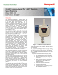
4905 Style Conductivity Cells Installation and Maintenance Manual 70-82-25-18 Revision 9 December 2011 Honeywell Process Solutions Copyright, Notices, and Trademarks Printed in U.S.A. – © Copyright 2007 by Honeywell Inc. Revision 9 – December 2011 While this information is presented in good faith and believed to be accurate, Honeywell disclaims the implied warranties of merchantability and fitness for a particular purpose and makes no express warranties except as may be stated in its written agreement with and for its customer. In no event is Honeywell liable to anyone for any indirect, special or consequential damages. The information and specifications in this document are subject to change without notice. Honeywell Honeywell Process Solutions 512 Virginia Drive Fort Washington PA 19034 ii 4905 Series Conductivity Cells – Installation and Maintenance December 2011 About This Document Abstract This document is intended to support the installation, operation and maintenance of the 4905 Series of Conductivity Cells. Revision Notes The following list provides notes concerning all revisions of this document. Rev. ID Date Notes 0 12/96 This document is the initial Honeywell release of the L&N manual p/n 177667 Rev. M2. There has been no significant changes only format changes to reflect the Honeywell layout. 1 6/99 Edits to add new Model Selection Guide 2 6/03 Removed obsolete info, added DL4000 details. 4 9/05 Edit text and add electrical connection drawings for UDA2182 analyzer 5 7/06 Added Platinizing information to Maintenance/ revised Parts List 6 12/07 Added CRN approval and quick disconnect option 7 June 09 Consolidation 8 Sept 11 Update wiring diagrams for Quick Disconnect cells 9 Nov 11 Mounting dimensions updated References Honeywell Documents The following list identifies all Honeywell documents that may be sources of reference for the material discussed in this publication. Document Title ID # APT2000CC Transmitter User Manual 70-82-25-95 APT4000CC Analyzer User Manual 70-82-25-104 UDA2182 Analyzer User Manual 70-82-25-119 World Wide Web The following lists Honeywell’s World Wide Web sites that will be of interest to our customers. Honeywell Organization WWW Address (URL) Corporate www.honeywell.com Honeywell Process Solutions www.honeywellprocess.com Telephone Contact us by telephone at the numbers listed below. Organization United States and Canada December 2011 Honeywell Phone Number Phone: 1-800-423-9883 Or 1-800-343-0228 Email: [email protected] 4905 Series Conductivity Cells – Installation and Maintenance iii Contents 1. INTRODUCTION ................................................................................................... 1 1.1 2. SPECIFICATIONS................................................................................................. 3 2.1 Specifications for 04905 Series ...................................................................................................... 3 2.2 Specifications for 276127 Flow Chamber ...................................................................................... 3 3. INSTALLATION .................................................................................................... 5 3.1 Overview ........................................................................................................................................ 5 3.2 Types of Mounting ......................................................................................................................... 6 3.3 The Differences between the Quick Disconnect and Integral Cable Option.................................. 6 3.4 Flow-Type Mounting ..................................................................................................................... 6 3.5 Immersion-Type Mounting for 04905 Series Cells........................................................................ 7 3.6 Insertion-Type Mounting ............................................................................................................... 7 4. ELECTRICAL CONNECTIONS........................................................................... 11 4.1 Overview ...................................................................................................................................... 11 4.2 Instrument Wiring for 4905 Cells with Integral Cable or Junction Box Head ............................. 12 4.2.1 Model 4905 Series with Integral Cable or Junction Box Head to UDA2182 Analyzer .... 12 4.2.2 Model 4905 Series with Integral Cable to APT Series Analyzer/Transmitter................... 14 4.2.3 Wiring Model 4905 with Quick Disconnect Cable to UDA2182...................................... 15 4.2.4 Wiring Model 4905 with Quick Disconnect Cable to APT............................................... 17 5. 6. iv Overview ........................................................................................................................................ 1 MAINTENANCE .................................................................................................. 19 5.1 Introduction .................................................................................................................................. 19 5.2 To Clean the Cell.......................................................................................................................... 19 5.3 To Check Conductivity System.................................................................................................... 19 5.4 Platinizing the Cell Electrodes ..................................................................................................... 20 REPLACEMENT PARTS AND ACCESSORIES................................................. 21 4905 Series Conductivity Cells – Installation and Maintenance December 2011 Figures Figure 3-1 Typical Conductivity Measuring Installation ______________________________________ 7 Figure 3-2 Dimension Drawing for 276127 Flow Housing ____________________________________ 8 Figure 3-3 Mounting Dimensions for 04905 Series with Integral cable___________________________ 9 Figure 3-4 Mounting Dimensions for 04905 Series with Junction Box Head ______________________ 9 Figure 3-5 Mounting Dimensions for 04905 Series with Quick Disconnect Option________________ 10 Figure 4-1 Installation Diagram, 4905 Cells, with Junction Box head connected to UDA2182 Analyzer 12 Figure 4-2 Installation Diagram, 4905 Cells, with 20′ or 50’ leads directly connected to UDA2182 Analyzer or connected to Junction Box_______________________________________________ 13 Figure 4-3 Model 4905 Series to APT Series Analyzer/Transmitter ____________________________ 14 Figure 4-4 Wiring Diagram for 4905 Cells with Quick Disconnect Cable Connected to UDA2182 Analyzer_______________________________________________________________________ 15 Figure 4-5 Installation diagram for 4905 cells with Quick Disconnect Cable connected to junction box 16 Figure 4-6 Wiring Diagram for 4905 Cells with Quick Disconnect Cable Connected to APT4000 ____ 17 Figure 4-7 Wiring Diagram for 4905 Cells with Quick Disconnect Cable Connected to APT2000 ____ 17 December 2011 4905 Series Conductivity Cells – Installation and Maintenance v Tables Table 3-1 Dimensions table for 04905 Series with Integral cable and Junction box head (All dimensions approximate)________________________________________________________ 10 Table 3-2 Dimensions table for 04905 with Quick Disconnect option (All dimensions approximate) __________________________________________________________________ 10 Table 5-1 Voltage and Time Limits for Platinizing Cells__________________________________ 20 vi 4905 Series Conductivity Cells – Installation and Maintenance December 2011 Introduction 1. Introduction 1.1 Overview These cells form the sensing network for industrial analyzers and transmitters designed to make continuous measurements of electrolytic conductivity. The cells are primarily suited to measurements in effluents of ion-exchangers and distillation columns; but appropriate constants are provided for many other applications, including measurements in micro-electronic component washing, plating-rinse effluents and acid/base concentrations. Universal in mounting, any of the cells can be arranged for immersion (for applications where the temperature does not exceed 85°C), insertion (1” NPT) or flow type sampling. The latter can be achieved by use of a flow chamber, such as Honeywell part number 276127 (See Figure 3-2). ATTENTION Please note that specific parameters of your process may prohibit the use of nickel elements. For example, use a platinum-element cell if the cell will measure or be exposed to regeneration acids or bases. ATTENTION Conductivity Cells are manufactured with an embedded EEProm that contains the cell constant and cell factor information. When the EEProm leads (Brown and Blue), junction box head terminals (E) and (F) are connected to a UDA2182 Analyzer these parameters are automatically uploaded into the analyzer. The cell constant is selected according to the range of the measuring instrument used and the solution measured. In general, a high-constant cell is used for solutions having low electrical resistance (high conductivity) and a low-constant cell is used for solutions having high electrical resistance (low conductivity). Automatic Temperature Compensation (ATC) during the measurement is provided by a built-in temperature sensing network located near the cross-channel or guard-tube holes. The cells are molded from Polyethersulfone (PES) which is resistant to most corrosive chemicals over a wide range of temperatures. (A common exception is chlorinated hydrocarbons.) Sample solutions come into contact only with the above plastic and the platinum, nickel or Monel electrode surface. Monel is available only on the 0.1 constant cell. December 2011 4905 Series Conductivity Cells – Installation and Maintenance 1 Introduction 2 4905 Series Conductivity Cells – Installation and Maintenance December 2011 Specifications 2. Specifications 2.1 Specifications for 04905 Series Parameter Description Cell Constant 04905 Series: 0.01, 0.1, 1.0, 10 and 50 as specified Electrode Material Nickel, Platinum or Monel as specified Maximum Pressure Limit 1724 kPa @ 140°C (250 psig @ 284°F) Maximum Continuous Temperature Limit 140°C (284°F) For immersion applications: 85°C (185°F) Materials of Construction Cell Body: PES (polyethersulfone) Support Fittings: Ryton Electrodes: Nickel, Platinum or Monel as specified Quick Disconnect Receptacle: 316 Stainless Steel Cable Options Leadwire: PVC insulated 22 gage cable, 0.245” OD, 20 and 50 feet lengths available. Quick Disconnect Option Mating cables must be purchased from Honeywell Universal Head (Aluminum) Weight Approximately 1 lb (0.45 kg) If using universal head: 3 lb (1.35 kg) Approvals Manufactured to comply with ASME boiler and pressure vessel code Section III, Div.1, UG-101 CRN #0F11607.5C Insertion 1” NPT male, Schedule 40 Flow Chamber Inlet: 3/4" MNPT Outlet: 3/4" FNPT Insertion Depth 5” to 7” (127 to 178 mm) depending on cell constant Overall Length Approximately 6 to 8” (152 to 203 mm) If using universal head: 10 to 12-1/4” (254 to 311 mm) 2.2 Specifications for 276127 Flow Chamber Parameter Description Maximum Flow 2 gpm @ 40psig and atmospheric discharge Maximum Pressure 200 psig @ 25°C Maximum Temperature 140°C (284°F) at atmospheric pressure Dimensions 1-1/2” (3.8 cm) octagon x 8-3/4” (22.2 cm) long. Sample Inlet: 3/4" MNPT Sample Outlet: 3/4" FNPT Cell Inlet: 1” MNPT Materials of Construction Polyethersulfone (PES) December 2011 4905 Series Conductivity Cells – Installation and Maintenance 3 Specifications 4 4905 Series Conductivity Cells – Installation and Maintenance December 2011 Installation 3. Installation 3.1 Overview The conductivity cell is secured permanently to the 1” N.P.T. bushing which is used for all types of mountings. Although the physical appearance of the various cells is the same (except for length), the cell construction differs according to the constant. On the 10 and 50 constant cells, the electrodes are short tubes located midway inside the two parallel tubular channels that run lengthwise through the cell, and are open to the sample at both ends of the cell. The channels are elliptical on the 10 constant cell. The 1, 0.1, and 0.01 constant cells have a removable cell guard which is screwed onto the cell body to protect the electrode surfaces. Electrodes are three disks on the 1 constant cell, parallel plates on the 0.1 constant cell, and wire wound on the cell body on the 0.01 constant cell. Cells must be used with the guard in place or the cell constant may differ from that specified. Most of the auxiliary parts which enable the user to achieve the various types of mounting are readily obtained from local suppliers. For an immersion mounting (only applicable in applications where the temperature does not exceed 85°C)with 04905 Series cells, only the appropriate length of 1/2 inch pipe (e.g., CPVC) and a 1/2 inch end coupling is needed. For an in-line flow mounting, only a 1” schedule 40 tee is required. The basic cell can be converted to a flow cell for either bypass or in-line arrangements by use of the PES flow-cell housing (Honeywell Part 276127) shown in Figure 3-2. However, the temperature and pressure specifications listed for this flow chamber under Specifications apply. December 2011 4905 Series Conductivity Cells – Installation and Maintenance 5 Installation 3.2 Types of Mounting There are three types of mounting: Flow, Immersion (for use in applications where temperatures do not exceed 85°C) and Insertion. Mounting dimensions for each type of cell assembly are given in Figure 3-4 and Figure 3-5. 3.3 The Differences between the Quick Disconnect and Integral Cable Option The cable options of quick disconnect and integral cable do not affect the performance of the cell. These options only relate to how the cell is connected to the instrument. ATTENTION •There are different electrical connections for these options. Please refer to Section 4 for instructions. NOTE: The wire colors for the integral cable and quick disconnect option are not the same. Do not use shielded cable except where shown in the following figures. Integral cable means the cable is potted into the cell. The cable and cell are one entity and cannot be separated. The quick disconnect option means the cell is connected to the cell by a receptacle on the top of the cell. The cell and the cable are separate entities. When the time comes to replace the cell, the cable does not have to be replaced. The cable can simply be mated with another cell that has the quick disconnect option. This option cannot be used in immersion applications. The cable must be purchased from Honeywell. 3.4 Flow-Type Mounting The cross-channel or guard-tube hole in the cell must always be covered by the solution and the solution level must be 1-1/2 inches above these holes. When mounting the cell in a pipe tee such as shown in Figure 3-1, have the solution enter the tee from below and exit to the side. As shown, the guard-tube hole is in line with the horizontal pipe run. However, if it is possible that the pipe line will not be full at all times, locate the hole just below the exit pipe to insure flooding of the cell under all conditions. As shown in Figure 3-1, always locate the cell on the pressure side, not the vacuum side of the pump. The flow-cellhousing, an accessory part having 3/4” male inlet and female outlet threads, can be used for an in-line measurement or in a bypass line as shown in Figure 3-1, depending upon the flow volume or pipe size. Adapter bushings are available to convert inlet and outlet fittings to 1/4” female threads. See Section 0 . The cell must be covered by the solution at all times. Therefore, make certain the lowest solution head is higher than the cell location. See that an air bubble does not prevent the cell from filling properly. Flow-cell housing can be used “in-line” only if a maximum flow of 2 gallons per minute can be tolerated. To avoid cracking the 276127 flow-cell housing, use Teflon tape on cell threads and tighten cell only enough to prevent leakage. To install, tighten the cell into a 1” schedule 40 pipe tee. If the flow-cell housing is used, assemble the cell and housing and install it in the process flow line or in a bypass line. 6 4905 Series Conductivity Cells – Installation and Maintenance December 2011 Installation Process Preferred Cell Locations Cooler 15" (381mm) Pump a/n 23383 Figure 3-1 Typical Conductivity Measuring Installation 3.5 Immersion-Type Mounting for 04905 Series Cells For use in applications where temperature does not exceed 85°C. The cell must be immersed to a level above the cross-channel or guard tube hole and must be immersed to 1-1/2 inches above this hole if an integral compensator is used. For most immersion applications, a 1/2” support pipe, preferably CPCV must be threaded into the cell bushing, using Teflon tape to seal the threads, thus permitting adequate immersion. Unless this pipe extension is used, do not immerse the top of the bushing. To insured that a representative sample is measured at all times, the solution must circulate through the channels. In quiescent solutions, provide sufficient agitation. To install the cell, determine the length of 1/2” pipe required to give the immersion needed to keep the cell completely immersed at all times. Remove the cap bushing at the top of the cell, slide it off the cable, and replace it with a ½”-inch coupling and the 1/2-inch pipe. At the top of the pipe install another pipe coupling and the cap bushing back over the leadwire, or install a junction box to terminate the pipe. 3.6 Insertion-Type Mounting The cell can be inserted into a 1” N.P.T. threaded opening, but it is imperative that the tank or chamber be full under all process conditions. Make certain the liquid head is above the cell location. A vertical insertion (from above) or a horizontal insertion can be used. To install, simply tighten the cell into a 1” N.P.T. threaded opening (using a Teflon thread compound such as Teflon tape) so that the entire electrode is immersed in the measured solution. Allow at least 1/2-inch clearance beyond the end of the cell. In applications where vertical mounting is required, avoid a position with the cell channels pointed up, as this will permit solution to flow down into the open end of the cell and may result in clogging by solids settling in the cell channels. See Figure 3-1. December 2011 4905 Series Conductivity Cells – Installation and Maintenance 7 Installation FlowOut 11/2" (38mm) Octagon 1 1/2" (38mm) 3/4" NPT 11/2" (38mm) Octagon 3/4" NPT IN CELL 11/2" (38mm) FlowChamber FlowIn 83/4" (222mm) 131/4" (337mm) 1" Fitting Allow73/4" (197mm) for removal o f cell Notes 1. Mount cell and flow chamber horizontally as shown above with flow exit “up to eliminate possible air gap around cell body. 2. If cell and flow chamber must be mounted vertically, attach a short length of tubing to flow exit as shown below and form a trap to ensure filing of flow chamber, especially at low flow. CELL 2" min. (51mm) IN Figure 3-2 Dimension Drawing for 276127 Flow Housing 8 4905 Series Conductivity Cells – Installation and Maintenance December 2011 Installation Figure 3-3 Mounting Dimensions for 04905 Series with Integral cable Figure 3-4 Mounting Dimensions for 04905 Series with Junction Box Head December 2011 4905 Series Conductivity Cells – Installation and Maintenance 9 Installation Table 3-1 Dimensions table for 04905 Series with Integral cable and Junction box head (All dimensions approximate) Cell Constant “X” mm inches “Y” mm inches 001 5.8” 147 0.94” 23.9 01 5.8” 147 0.94” 23.9 1 5.8” 147 0.94” 23.9 10 6.0” 152 0.84” 21.3 50 7.3” 185 0.84” 21.3 Table 3-2 Dimensions table for 04905 with Quick Disconnect option (All dimensions approximate) Cell Constant “X” mm inches “Y” mm inches “Z” mm inches 001 5.8” 147 8.7” 221 0.84” 21.3 01 5.8” 147 8.7” 221 0.84” 21.3 0 5.8” 147 8.7” 221 0.84” 21.3 10 6.0” 152 9.1” 231.1 0.94” 23.9 50 7.3” 185 10.2” 259.1 0.94” 23.9 Figure 3-5 Mounting Dimensions for 04905 Series with Quick Disconnect Option 10 4905 Series Conductivity Cells – Installation and Maintenance December 2011 Electrical Connections 4. Electrical Connections 4.1 Overview The terminal board connections for the various Honeywell measuring instruments are given in the appropriate Figures in this section. To avoid the possibility of AC pickup in the cell leads, separate them from all AC line-voltage wiring or run them in a separate grounded conduit. ATTENTION Do not use shielded cable except where shown in the following figures. WARNING EEPROM memory device is ESD sensitive- blue and brown leads; junction box head terminals (E) and (F) December 2011 4905 Series Conductivity Cells – Installation and Maintenance 11 Electrical Connections 4.2 Instrument Wiring for 4905 Cells with Integral Cable or Junction Box Head 4.2.1 Model 4905 Series with Integral Cable or Junction Box Head to UDA2182 Analyzer Drawing 50043652 Figure 4-1 Installation Diagram, 4905 Cells, with Junction Box head connected to UDA2182 Analyzer 12 4905 Series Conductivity Cells – Installation and Maintenance December 2011 Electrical Connections 50 FT. MAX. WIRE. 20 FT. OR 50 FT. CABLE LENGTH. Figure 4-2 Installation Diagram, 4905 Cells, with 20′ or 50’ leads directly connected to UDA2182 Analyzer or connected to Junction Box December 2011 4905 Series Conductivity Cells – Installation and Maintenance 13 Electrical Connections 4.2.2 Model 4905 Series with Integral Cable to APT Series Analyzer/Transmitter Blue and Brown leads not used 04905 series cells with leads connected to an APT4000 Blue and Brown leads not used 04905 series cells with leads connected to an APT2000 Figure 4-3 Model 4905 Series to APT Series Analyzer/Transmitter 14 4905 Series Conductivity Cells – Installation and Maintenance December 2011 Electrical Connections 4.2.3 Wiring Model 4905 with Quick Disconnect Cable to UDA2182 Figure 4-4 Wiring Diagram for 4905 Cells with Quick Disconnect Cable Connected to UDA2182 Analyzer December 2011 4905 Series Conductivity Cells – Installation and Maintenance 15 Electrical Connections Figure 4-5 Installation diagram for 4905 cells with Quick Disconnect Cable connected to junction box 16 4905 Series Conductivity Cells – Installation and Maintenance December 2011 Electrical Connections YELLOW Only use color leads as indicated. Ignore all others. COAX 4.2.4 Wiring Model 4905 with Quick Disconnect Cable to APT Figure 4-6 Wiring Diagram for 4905 Cells with Quick Disconnect Cable Connected to APT4000 Only use color leads as indicated. Ignore all others. Figure 4-7 Wiring Diagram for 4905 Cells with Quick Disconnect Cable Connected to APT2000 December 2011 4905 Series Conductivity Cells – Installation and Maintenance 17 Electrical Connections 18 4905 Series Conductivity Cells – Installation and Maintenance December 2011 Maintenance 5. Maintenance 5.1 Introduction If abnormal readings occur, this may indicate poor response because the cell is not filled with process solution. Check the cell installation. Note that a grayish dull surface on the cell plastic (normally glassy) can result from exposure to temperatures above 140C. The only maintenance which may be required is occasional cleaning in certain applications. Cell constants 0.01, 0.1, and 1 cannot be used if solution resistance measures less than 1000 ohms unless the cell is platinized in accordance with Section 5. 5.2 To Clean the Cell The cell will require cleaning if sludge, slime, etc., accumulates in the flow channels. Since the materials of construction are chemically inert, chemical agents may be used and are recommended for cleaning the cells. The particular cleaning agent used must be selected according to the type of contamination to which the cell is exposed. CAUTION The cell housing is PES (Polyethersulfone). DO NOT clean with acetone, chloroform, toluene, benzene, or any other chlorinated hydrocarbon. In general, soap and hot water are effective and adequate. If necessary, a soft bristle brush of about 1/4” diameter may be used to clean out the tubular channels of the 10 and 50 constant cells. Do not scratch the electrode surfaces. Be especially careful not to bend the electrode plates of the 0.1 constant cell. Rinse the cell thoroughly in tap water and then in distilled water if available. 5.3 To Check Conductivity System To check the conductivity system comprising conductivity cell, leadwire, and measuring instrument, the user may desire to make a measurement in a reference solution of known conductivity. Control the temperature only within limits consistent with the desired accuracy. The 25C temperature value is suggested. The solutions may be prepared in the presence of air. The solution must fill the cell during measurement. For optimum accuracy in acid measurements above 5% concentration, use the “Calibration Trim” function available in the conductivity instrument. See the appropriate Analyzer/Transmitter manuals for details on the trim function. To check the constant of a cell, use a second cell having the same constant and compare the reading of one against the other. If the 04905 Series conductivity cell model number contains ‘333’, the normal resistance of the temperature sensor as measured across the red (B) and green (D) leads is 8550 ohms at 25C. To check the electrode insulation, connect an ohmmeter across the black (A) and white (C) leads (coax and yellow for QD option). With a dry and clean cell, the resistance should be greater than 50 megohms. NOTE: Never connect a test instrument access the Blue (E) and Brown (F) leads. Damage to the cell memory device may occur. December 2011 4905 Series Conductivity Cells – Installation and Maintenance 19 5.4 Platinizing the Cell Electrodes Only the electrodes having constants 10 and 50 must be replatinized if the velvety-black deposit has been rubbed off the electrodes in service or in cleaning or if platinized electrodes are recommended and this black deposit is not present when the new cell is received. Always replatinize if a brush was used in cleaning the electrodes. The indication of a need for replatinization of the electrodes is loss in sensitivity (slow response of measuring instrument), erratic behavior of measuring instrument, or difficulty in balancing. The electrodes of the high constant cells are not visible since they are located near the middle of the flow channels. Therefore the need for platinization is only indicated by the effect on the measuring instrument. Do not platinize cells intended for high purity water measurements. Before platinizing, clean the cell with detergent and brush as described in Section 5.2. Support the cell in a cylindrical vessel with the end of the cell raised from the bottom. It is not necessary to remove the cell from the fittings for platinizing. However, the guard tube must be removed from the low constant cells. Pour in a platinizing solution to a level above the cross-channel. To platinize the 10 or 50 constant cells, immerse an auxiliary platinum electrode in the solution to a point about midway between the cross-channel or tube hole and the open end of the cell. (This third electrode should be chemically pure platinum. Its shape is unimportant. It may be one of the electrodes in another conductivity cell or a platinum strip, sheet, rod, wire, etc.) Both electrodes of the cell are platinized simultaneously by connecting the negative terminal of the battery (see Table 5-1) to both leadwires of the cell. Connect the positive terminal of the battery to the auxiliary platinum electrode. Note the time lapse and continue the platinizing operation for the time in seconds listed in Table 5-1. Then disconnect the battery and remove the cell. Rinse the cell thoroughly in tap water and then rinse in distilled water. During the platinizing operation, move the cell up and down gently to keep the solution stirred. CAUTION The preceding procedure produces a barely visible coating of platinum black on the electrode surfaces. Do not attempt to darken electrodes by additional platinization since this will affect the cell performance adversely. Pour the platinizing solution back into its container as it may be used a number of times. If the cell is not to be installed immediately after platinizing, it should be kept submerged in distilled water until put into use, as platinum black is not stable when dry. Table 5-1 Voltage and Time Limits for Platinizing Cells DC 10 50 Volts 20 6.0 100 sec. 300 sec. 12.0 ---- 240 sec. 4905 Series Conductivity Cells – Installation and Maintenance December 2011 Replacement Parts and Accessories 6. Replacement Parts and Accessories Description Part Number Flow Cell Housing, PES 276127 Junction Box 31316260 CPVC Pipe cap 50028816-501 Extension Cables for Sensors with Quick Disconnect Option 2m (6.56 ft) 50024092-501 3m (9.84 ft) 50024092-502 6m (19.69 ft) 50024092-503 15m (49.21 ft) 50024092-504 30m (98.43 ft) 50024092-505 EXTENSION CABLE MUST BE PURCHASED FROM HONEYWELL Cell Extension Leadwire (see Fig 4.1 & 4.2 for required cables) 18 AWG, Low capacitance shielded twisted pair BELDEN 8760 or equivalent 22 AWG, Coax RG59U BELDEN 9259 or equivalent 18 AWG, 4 conductor BELDEN 8489 or equivalent December 2011 4905 Series Conductivity Cells – Installation and Maintenance 21 22 4905 Series Conductivity Cells – Installation and Maintenance December 2011 Introduction Sales and Service For application assistance, current specifications, pricing, or name of the nearest Authorized Distributor, contact one of the offices below. Asia Pacific Global Technical Support Field Instruments Phone: +65 6580 3156 Fax: +65 6445-3033 Australia Honeywell Limited Phone: +(61) 7-3846 1255 FAX: +(61) 7-3840 6481 Toll Free 1300-36-39-36 Toll Free Fax: 1300-36-04-70 China – PRC - Beijing Honeywell China Inc. Phone: +(86-10) 84583280 Fax: +(86-10) 8458-4650 China – PRC - Shanghai Honeywell China Inc. Phone: (86-21) 5257-4568 Fax: (86-21) 6237-2826 China – PRC - Chengdu Honeywell China Inc. Phone: +(86-28) 66135078 Fax: +(86-28) 8678-7061 China – PRC - Xi’an Honeywell China Ltd Xi’an. Phone: +(86-29) 88337490 Fax: +(86-29) 8833-7489 New Zealand Honeywell Limited Phone: +(64-9) 623-5050 Fax: +(64-9) 623-5060 Toll Free (0800) 202-088 Denmark Honeywell A/S Phone: +(45) 39 55 55 55 FAX: +(45) 39 55 55 58 Spain Honeywell S.A. Phone: +34 (0)91313 61 00 FAX: +34 (0)91313 61 30 Singapore Honeywell Pte Ltd. Phone: +(65) 6580 3278 Fax: +(65) 6445-3033 Finland Honeywell OY Phone: +358 (0)20752 2753 FAX: +358 (0) 20752 2751 Sweden Honeywell AB Phone: +(46) 8 775 55 00 FAX: +(46) 8 775 56 00 South Korea Honeywell Korea Co Ltd Phone: +(822) 799 6114 Fax: +(822) 792 9015 France Honeywell SA Phone: +33 (0)1 60198075 FAX: +33 (0)1 60198201 Thailand Honeywell Systems (Thailand) Ltd. Phone: +(662) 693-3099 FAX: +(662) 693-3089 Germany Honeywell GmbH Phone: +49 (69)8064-299 FAX: +49 (69)8064931 Taiwan R.O.C. Honeywell Taiwan Ltd. Phone: +(886-2) 22451000 FAX: +(886-2) 22453243 SE Asia Countries see Honeywell Pte Ltd (Singapore) for: Philippines, Pakistan, Cambodia, Guam, Laos, Myanmar, Vietnam, East Timor SE Asia Countries China – PRC - ShenzhenHoneywell China Inc. Phone: +(86) 755-25181226 Fax: +(86) 755-2518-1221 see Honeywell Automation India Ltd for: Bangladesh Nepal Sri Lanka Indonesia PT Honeywell Indonesia Phone: +(62) 21-535-8833 FAX: +(62) 21-5367 1008 EUROPE Honeywell Automation India Ltd. Honeywell Ltd. Phone:+(91) 6603-9400 Fax: +(91) 6603-9600 Japan Honeywell Inc. Phone: +(81) 3 6730 7197 Fax: +(81) 3 6730 7228 Malaysia Honeywell Engineering Sdn Bhd Phone: +(603) 7958-4788 Fax: +(603) 7958-8922 Austria Honeywell Austria GmbH Phone: +43 (316)400123 FAX: +43 (316)40017 Belgium Honeywell SA/NV Phone:+32 (0)2728 24 07 FAX: +32 (0)2728 22 45 Bulgaria Honeywell EOOD Phone: +(359) 2 40 20 900 FAX: +(359) 2 40 20 990 Czech Republic Honeywell spol. s.r.o. Phone:+420 242 442 232 FAX: +420 242 442 131 Hungary Honeywell Kft. Phone: +36-1-451 4300 FAX: +36-1-451 4343 Italy Honeywell S.p.A. Phone:+390292146307 FAX: +39 0292146377 The Netherlands Honeywell B.V. Phone: +31 (0) 20 5656200 FAX: +31 (0) 20 5656210 Norway Honeywell A/S Phone: (45) 39 55 55 55 Poland Honeywell Sp. zo.o Phone: +48-22-6060900 FAX: +48-22-6060901 Portugal Honeywell Portugal Lda Phone: +351 21 424 5000 FAX: +351 21 424 50 99 Romania Honeywell Bucharest Phone: +40 (0) 21 2316437 FAX: +40 (0) 21 2316439 Russian Federation (RF), Honeywell Field Solutions Kievskaya str., 7, Moscow 121059, Russia Phone +7 (495) 796 98 60 Fax +7 (495) 797 99 64 Slovak Republic Honeywell s.r.o. Phone: +421-2-58247 410 FAX: +421-2-58247 415 12/7/11 Switzerland Honeywell AG Phone: +41 18552448 FAX: +(41) 1 855 24 45 Turkey Honeywell Turkey A.S. Phone: +90 216 578 71 00 FAX: +90 216 575 66 35 Ukraine Honeywell Tel: +380-44-351-15-50 Fax: +380-44-351-15-51 United Kingdom Honeywell Control Systems Ltd. Phone: +44 (0)1344 655251 FAX: +44 (0) 1344 655554 MIDDLE EAST Abu Dhabi U A E Middle East Headquarters Honeywell Middle East Ltd. Phone: +971 2 4041246 FAX: +971 2 4432536 Sultanate of Oman Honeywell & Co Oman LLC Phone: +968 24 701153/ Ext.33 FAX +968 24 787351 Saudia Arabia Honeywell Turki Arabia Ltd Jubail Office Phone: +966-3-341-0140 Fax: +966-3-341-0216 Honeywell - ATCO Dammam Office Phone: 0096638304584 Fax: 0096638338059 Kuwait Honeywell Kuwait KSC Phone: +965 242 1327 to 30 Fax: +965 242 8315 And Phone: +965 326 2934/1821Fax: +965 326 1714 AFRICA Mediterranean & African Distributors Honeywell SpA Phone: +39 (02) 250 10 604 FAX: +39 (02) 250 10 659 South Africa (Republic of) and sub saharan Honeywell Southern Africa Honeywell S.A. Pty. Ltd. Phone: +27 11 6958000 FAX +27 118051504 NORTH AMERICA Canada Honeywell LTD Phone: 1-800-737-3360 FAX: 1-800-565-4130 USA Honeywell Process Solutions, Phone: 1-800-423-9883 Or 1-800-343-0228 Email: [email protected] SOUTH AMERICA Argentina Honeywell S.A.I.C. Phone: +(54-11) 4383-3637 FAX: +(54-11) 4325-6470 Brazil Honeywell do Brasil & Cia Phone: +(55-11) 7266-1900 FAX: +(55-11) 7266-1905 Chile Honeywell Chile, S.A. Phone: +(56-2) 233-0688 FAX: +(56-2) 231-6679 Mexico Honeywell S.A. de C.V. Phone: +(52) 55 5259-1966 FAX: +(52) 55 5570-2985 Puerto Rico Honeywell Inc. Phone: +(809) 792-7075 FAX: +(809) 792-0053 Trinidad Honeywell Inc. Phone: +(868) 624-3964 FAX: +(868) 624-3969 Venezuela Honeywell CA Phone: +(58-2) 238-0211 FAX: +(58-2) 238-3391 23 Honeywell Proprietary