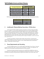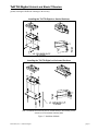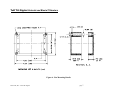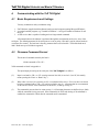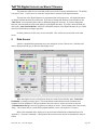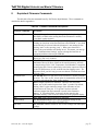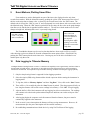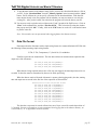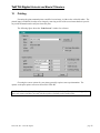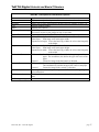
1
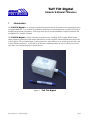
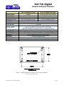
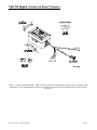
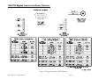
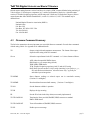
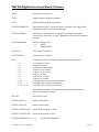
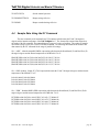
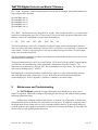
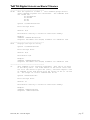
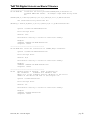
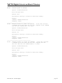
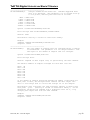
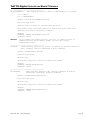
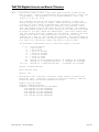
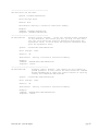
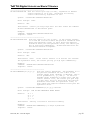
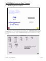
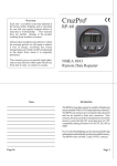
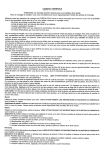
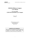
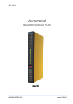
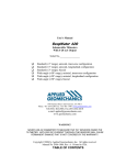
USER’S MANUAL TUFF TILT DIGITAL Uniaxial and Biaxial Tiltmeters Serial No.________________ +/− 3 degrees +/-50 degrees Uniaxial (Transverse Tilt) Uniaxial (Longitudinal Tilt) Biaxial RS232 RS485 1336 Brommer Street Santa Cruz, CA 95062 USA Tel (831) 462-2801 Fax (831) 462-4418 [email protected] www.geomechanics.com Copyright ©2006 by Applied Geomechanics Inc. All rights reserved. Document No. B-06-1006 Rev. A Tuff Tilt Digital Uniaxial & Biaxial Tiltmeters 1 Introduction The Tuff Tilt Digital is an exciting new digital instrument for indoor and outdoor work requiring precision and rugged durability. It is excellent for continuous monitoring of structural behavior, or short-term testing of machine and structural performance. It fills a gap between our economical MD900-T Digital Clinometer and our Model D711 Scientific Tiltmeter. The Tuff Tilt Digital is offered with many powerful features, including: RS232 output, RS485 output, analog output or optional tilt switch output in the RS232 versions, biaxial or uniaxial measurement, and 16-bit A/D resolution. The serial data output is easily interfaced to many GPS receivers, spread spectrum radios, and wireless Ethernet converters. A powerful set of firmware commands enables the user to collect, process and store data, or to send data directly to external devices. Figure 1. Tuff Tilt Digital B-06-1006, Rev. A Tuff Tilt Digital page 1 Tuff Tilt Digital Uniaxial & Biaxial Tiltmeters Tuff Tilt Digital (Standard) ANGULAR RANGE RESOLUTION REPEATABILITY TEMPERATURE COEF. CHANNELS LINEARITY TIME CONSTANT DIGITAL OUTPUT OUTPUT DATA RATE POWER REQ’TS ENVIRONMENTAL MOUNTING MATERIALS CABLE & CONNECTOR SIZE & WEIGHT Tuff Tilt Digital (Wide Angle) ±3 degrees ±50 degrees (greater range available) 0.0001 degree 0.002 degree 0.0003 degree (1 arc second), static 0.004 degree, static Zero: ±0.0002 degree/°C typical Zero: ±0.004 degree/°C typical Single-axis or dual-axis with 2 orthogonal tilt channels, 1 temperature channel < 0.1% of full span 0.15 second RS232 or RS485, transmit and receive Baud rate: 9600 (default), 19200, 28800, 57600, 115200, 230400 NMEA 0183 compatible (x, y, temperature, serial no.), plus other output strings User-selectable from 10 samples/second to 1 sample/24 hours 7 to 26 VDC @ 27 mA, 250 mV peak-to-peak ripple maximum, reverse polarity protected −25° to +70°C operational, −30° to +100°C storage. NEMA 4X (IP65) Four no. 8 stainless steel mounting screws included Die cast and painted aluminum 3m (10 ft), 6 conductors + one overall shield, PVC jacket. DB9 connector for digital I/O. 120 x 80 x 60 mm (4.7x 3.2 x 2.4 inches), 0.6 kg (1.5 lb) Figure 2. Mounting holes are accessed by removing lid of tiltmeter. Use 8-32 or 4 mm screws. B-06-1006, Rev. A Tuff Tilt Digital page 2 Tuff Tilt Digital Uniaxial and Biaxial Tiltmeters Figure 3. Cable termination details: Tinned ends (left) for power and optional analog or tilt switch output, DB9 connector for serial communications, and barrel connector for power input using optional power supply part no. 00254-02. B-06-1006, Rev. A Tuff Tilt Digital page 3 Tuff Tilt Digital Uniaxial and Biaxial Tiltmeters Figure 4. Wiring connections, Tuff Tilt Digital B-06-1006, Rev. A Tuff Tilt Digital page 4 Tuff Tilt Digital Uniaxial and Biaxial Tiltmeters Description & Order Numbers ±3 degrees, Uniaxial, Transverse ±3 degrees, Uniaxial, Longitudinal ±50 degrees, Uniaxial, Transverse ±50 degrees, Uniaxial, Longitudinal ±3 degrees, Biaxial ±50 degrees, Biaxial Communications Protocol RS232* RS485 98031-02 98034-02 98031-05 98034-05 98031-03 98034-03 98031-06 98034-06 98033-02 98035-02 98033-03 98035-03 * RS232 version is available with optional analog X, Y output or tilt switch output. Please specify when ordering. Accessories Extra cable Horizontal mounting plate Vertical mounting bracket Power supply (110-240 VAC) 2. Order No. 70369 84051 81439 00254-02 Installing the Tiltmeter, Making Connections, Tilt Directions For best results, the tiltmeter should be fastened to a rigid metal or concrete base using four machine screws (no. 8 or M4 size). To access the four mounting holes, first remove the lid of the clinometer (Figure 2). The base to which you will attach the clinometer should be drilled in advance with four threaded or through holes. Use a bolt anchoring system if the base is concrete. The hole pattern must match the 107 x 67 mm hole mounting hole pattern of the clinometer. For stable readings, the mounting screws should hold the clinometer tightly against the base so that it cannot shift or wobble. Replace the lid when installation is complete. Note: Our horizontal mounting plates and vertical mounting brackets simplify the installation. See the accessory table above and also Figure 5. To operate your clinometer, connect the cable assembly as shown in Figure 4. Provide power by connecting the transformer to the power input connector, or use the auxiliary power leads and a separate power supply. Connect the DB9 serial interface connector to a PC or terminal and then follow the instructions in Section 4. Tilt directions are shown in Figure 3. 3. Power Requirements and Grounding Your Tuff Tilt Digital operates on 7-28 volts DC and draws approximately 30 mA of power. Power and ground are connected at pins 2 and 1 respectively of the 6-pin connector. See Figure 4 for wiring details. The enclosure (case) is not grounded except through tranzorbs used for surge protection. Transient surge absorbers (tranzorbs) connect the power, ground, RS232 and RS485 pins to the case. Screwing the case to a metal substrate at the four mounting holes will ground the case (Figures 2). If the substrate is grounded to the earth, high-voltage transients traveling down the clinometer cable will have a path to earth B-06-1006, Rev. A Tuff Tilt Digital page 5 Tuff Tilt Digital Uniaxial and Biaxial Tiltmeters ground, reducing the likelihood of damage to the circuitry. Installing the Tuff Tilt Digital on Vertical Surfaces Installing the Tuff Tilt Digital on Horizontal Surfaces Note: The tiltmeter enclosure may also be screwed directly to the mounting surface without use of the P/N 84051 Mounting Plate Figure 5. Installation Methods B-06-1006, Rev. A Tuff Tilt Digital page 6 Tuff Tilt Digital Uniaxial and Biaxial Tiltmeters Figure 6. Box Mounting Details B-06-1006, Rev. A Tuff Tilt Digital page 7 Tuff Tilt Digital Uniaxial and Biaxial Tiltmeters 4. Communicating with the Tuff Tilt Digital 4.1 Basic Requirements and Settings You may communicate with your tiltmeter using: 1. ZAGI Software (supplied with the tiltmeter) and a personal computer running Microsoft Windows; 2. A terminal emulator program (e.g. Terminal in Windows 3.1 or HyperTerminal in Windows 95 and later); or 3. A GPS receiver that is capable of sending and receiving terminal commands. All communication to the tiltmeter is performed through the send (transmit) and receive wires of the serial port. The default parameters for the serial port are set to no parity, 8 bits and 1 stop bit with no hardware or software flow control. The baud rate is the only parameter that is user-selectable. The default baud rate is 9600. Baud rates up to 230400 are supported. 4.2 Firmware Command Format The format of commands issued by the host is: *9900<command><CR><LF> Valid commands are listed in Appendix A. The input/output processing on the serial port of the Tuff Tilt Digital is as follows: (1) Input is read until a <CR> or <LF> (carriage return or line feed) is received. (On a PC, this usually means pressing the ‘Enter’ or ‘Return’ key.) (2) When a line is received, it is parsed to see if it is a command of the device. If it is not, then it is echoed back out, terminated with a <CR> <LF> and we go back to step (1). All strings that are not commands for the unit are echoed. If the command is for the device, we then go to step (3). (3) The command is processed and we return to step (1). All incoming characters are buffered (up to 1000) while the command is being processed. If the command is for ID 99 and echoing of 99 commands is enabled, the command is echoed after the command result is transmitted. B-06-1006, Rev. A Tuff Tilt Digital page 8 Tuff Tilt Digital Uniaxial and Biaxial Tiltmeters Default output running firmware version 5 and above is a simple (“SIM”) comma-delimited string consisting of X tilt in degrees, Y tilt in degrees, temperature in ºC, and the serial number of the device. Optional outputs consist of a Trimble Navigation proprietary ASCII string with X (Roll) and Y (Pitch) tilts in degrees, and two output formats that follow NMEA Standard 0183, version 2.1, October 15, 1995. This standard may be obtained from: National Marine Electronics Association (NMEA) National Office P.O. Box 3435 New Bern, NC 28564-3435 USA Tel: 919/638-2626 Fax: 919/638-4885 4.3 Firmware Command Summary The list below summarizes the most important user-accessible firmware commands. Precede these commands with the string *9900. See Appendix A for additional details. XY Outputs a single tilt and temperature measurement. The format of the output depends on the setting of the SO command. SO-xxx Selects the output format for the XY command. “xxx” selects format as follows: ASH: Ashtech compatible NMEA format SIM: Simple x,y,t,sn output string (default) XDR: NMEA XDR format TCM: Trimble Navigation proprietary pitch (Y) and roll (X) string BAE: BAE Systems encoded 11-byte string containing a sync packet, x, y, t, SN, and checksum information. Advanced users only—typically for embedded system integration. XY-MEMS Stores tiltmeter readings at selected output rate in nonvolatile memory. (Versions 5.1 and higher) XY-MEMD Downloads data from nonvolatile memory. (Versions 5.1 and higher) XY-M1 Sets the tiltmeter to Mode-1 operation. XYVR Displays the sign-on string. ID Sets the ID of units in the daisy chain (not currently implemented). XY-TR-PASH-ON Translates the Paros provided $PASHS,XDR,P sentences to standard NMEA XDR format. XY-TR-PASH-OFF Turns off translation of $PASHS,XDR,P sentences. XY-EP Enables power on message. B-06-1006, Rev. A Tuff Tilt Digital page 9 Tuff Tilt Digital Uniaxial and Biaxial Tiltmeters XY-SP Disables power on message. XY-EE Enables echoing of global 99 commands. XY-SE Disables echoing of global 99 commands. XY-SET-BAUDRATE,x Sets baud rate to value of x in bits per second. Selectable values include 9600, 19200, 28800, 57600, 115200 and 230400 baud. XY-SET-N-SAMP,x Sets number of samples that are averaged before a reading is transmitted; x may have any value from 1 to 1000. Changing this value may also change the output rate. XY-SET-RSMODE,x Selects serial output mode: x=0 RS232 x=1 RS485 (RS422) XY-AUTOZ Turns on auto zero function. XY-AUTOZOFF Turns off auto zero function. XYCx Continuously sends XY data where x determines output rate as follows: x = 0: x = 1: x = 2: x = 3: x = 4: x = 5: x = 6: x = 7: x = 0A: x = 1A: x = 2A or x = A: 8-10 outputs per second 4 outputs per second 1 output per second (default) 1 output every 10 seconds 1 output every 60 seconds 1 output every hour 1 output every 12 hours 1 output every 24 hours Averaging of the 8-10 outputs per second data Averaging of the 4 outputs per second data Averaging of the 1 output per second data Once initiated, continuous output remains in effect until turned off with the XYC-OFF command (see below). XYC-OFF Turns off XYC mode. XY-SET-CTRL-ON Enables control feature. XY-SET-CTRL-OFF Disables control feature. XY-SET-CTRLTEST-ON Sets the control pin high (+5 VDC). XY-SET-CTRLTEST-OFF Sets the control pin low (0 VDC). XY-SET-THRESHOLD,x+,x-,y+,y- B-06-1006, Rev. A Tuff Tilt Digital Sets the control thresholds. page 10 Tuff Tilt Digital Uniaxial and Biaxial Tiltmeters XY-SET-HYST,k Sets the control hysteresis. XY-DUMP-SETTINGS Dumps settings of device. XY-DUMP2 Dumps extended settings of device. 4.4 Sample Data Using the XY Command The most commonly used command is the XY command, which returns the X and Y tilt angles in degrees and the internal temperature of the Tuff Tilt Digital in ºC. The format of the returned data depends on the setting of the SO command. The returned data are averages of a series of readings. The number of samples used in the average is set by the XY-SET-N-SAMP command. The following lines illustrate the format of the data returned by the XY command for the range of possible SO settings: SO = “ASH.” Ashtech compatible NMEA output string which returns the North-South (Y) and East-West (X) tilt angle in degrees and the internal temperature of the MD-900-T in ºC: $PASHS,XDR,A,004.261,D,N,A,004.280,D,E,C,021.288,C,T-N1346 $PASHS,XDR,A,004.261,D,N,A,004.280,D,E,C,021.306,C,T-N1346 $PASHS,XDR,A,004.261,D,N,A,004.280,D,E,C,021.298,C,T-N1346 $PASHS,XDR,A,004.261,D,N,A,004.280,D,E,C,021.332,C,T-N1346 SO = “SIM” (default). Simple X,Y,T,SN output which returns the X and Y tilt angle in degrees and the internal temperature of the MD-900-T in ºC: $-00.619,000.023,018.910,N0000 $-00.619,000.023,018.923,N0000 $-00.620,000.024,018.932,N0000 $-00.620,000.023,018.951,N0000 SO = “XDR.” Standard NMEA XDR output string which returns the North-South (Y) and East-West (X) tilt angle in degrees and the internal temperature of the MD-900-T in ºC: $YXXDR,A,000.034,D,N,A,-00.625,D,E,C,021.651,C,T-N0000*47 $YXXDR,A,000.034,D,N,A,-00.624,D,E,C,021.675,C,T-N0000*40 $YXXDR,A,000.034,D,N,A,-00.624,D,E,C,021.686,C,T-N0000*4C $YXXDR,A,000.034,D,N,A,-00.625,D,E,C,021.707,C,T-N0000*45 B-06-1006, Rev. A Tuff Tilt Digital page 11 Tuff Tilt Digital Uniaxial and Biaxial Tiltmeters SO = “TCM.” Proprietary Trimble Navigation pitch (Y-tilt) and roll (X-tilt) output string which returns the tilt angle in degrees and a checksum: $P-00.907R002.186*1C $P-00.906R002.183*18 $P-00.908R002.191*15 $P-00.908R002.191*15 $P-00.905R002.190*19 SO = “BAE.” Advanced users only, using the D711-2A(4X). BAE Systems encoded 11-byte output which returns two synchronization bytes, the X (2 bytes) and Y (2 bytes) tilt angle, the internal temperature of the tiltmeter (2 bytes), the serial number (2 bytes), and a checksum byte: Uª Ä$é TæUª Ä$ä TáUª Ä$ß TÜUª Ä$é Tæ The BAE output string is not clearly decipherable by HyperTerminal, which sometimes hides characters that it has received and cannot understand. Because of this, it is difficult, if not impossible, to interpret data in this format. The above output string shows four outputs taken from HyperTerminal. The BAE output string is not selectable using ZAGI. This encoded output command is typically used to communicate with embedded systems, as they can view raw data and perform fast translations. The first synchronization byte is 0x55, the second is 0xAA. The X and Y bytes use 0.0000277 angular degrees per LSB, hence the total output range of this output mode is limited to the model D711-2A(4X). The temperature uses 0.004 degrees Celsius per LSB. The serial number is a two byte integer. The checksum byte is the result of ANDing bytes 2-7 with 255. BAE output mode reduces the total number of characters per output to 11 bytes, while transferring the same data as the SIM output mode, which requires 33 bytes. BAE mode also includes checksum and frame synchronization bytes. Refer to Appendix A, Firmware Commands, to decode the output. 5. Maintenance and Troubleshooting The Tuff Tilt Digital is packaged in a rugged aluminum box and should provide many years of trouble-free operation. Best results are achieved by keeping the unit clean, dry and within the stated operating and storage temperature ranges. Problems most commonly result from lack of power, or a broken wire or connection. If the unit does not respond when queried by the host, first verify that it is receiving power. If it still does not respond, remove the lid and check for loose broken wires or a loose or detached internal connector. If these checks still do not reveal the problem, contact Applied Geomechanics in California for assistance at telephone: 831/462-2801, fax: 831/462-4418 or e-mail: [email protected] . B-06-1006, Rev. A Tuff Tilt Digital page 12 Tuff Tilt Digital Uniaxial and Biaxial Tiltmeters Appendix A. Firmware Commands B-06-1006, Rev. A Tuff Tilt Digital page 13 Tuff Tilt Digital Uniaxial and Biaxial Tiltmeters Firmware Commands Valid commands are listed below. Some commands have more than one string to trigger the command. “tt” stands for the target ID (99) and “ss” stands for the source ID (00). Settings stored in nonvolatile memory remain in effect until disabled, even after a power cycle. --------------------------------------XY Outputs a single tilt measurement. The format of the output depends on the setting of the SO command. Syntax: *ttssXY<CR><LF> Error Strings: None. Default: N/A Persistence: N/A Example: command: *9900XY<CR><LF> response: $YXXDR,A,-00.920,D,N,A,-00.210,D,E,C,030.045,C,T-N1212*57 --------------------------------------SO Selects the output format for the XY command. are: The possible formats -SIM $x.x,y.y,t.t,sn<CR><LF> | | | | | | | Serial number | | Temperature of tiltmeter | Y-tilt value in degrees X-tilt value in degrees Example: $-00.920,-00.210,030.045,N1212 -XDR $YXXDR,A,x.x,D,N,A,x.x,D,E,C,x.x,C,T-sn*hh<CR><LF> | | | | | | | | | | | | | | | | | | | | | | | | | | | Checksum | | | | | | | | | | | | Serial number | | | | | | | | | | | Comment, T for temperature | | | | | | | | | | Units, C=degrees C | | | | | | | | | Temperature of tiltmeter | | | | | | | | Data Type, C=Temperature | | | | | | | Comment, E for East/West (X) direction | | | | | | Units, M=microradians, D=degrees | | | | | X (E)-tilt value | | | | Data Type, A=Angular | | | Comment, N for North/South (Y) direction | | Units, M=microradians, D=degrees, | Y (N)-tilt value Data Type, A=Angular Example: $YXXDR,A,-00.920,D,N,A,-00.210,D,E,C,030.045,C,T-N1212*57 B-06-1006, Rev. A Tuff Tilt Digital page 14 Tuff Tilt Digital Uniaxial and Biaxial Tiltmeters -ASH $PASHS,XDR,A,x.x,D,N,A,x.x,D,E,C,x.x,C,T-sn<CR><LF> | | | | | | | | | | | | | | | | | | | | | | | | | Serial number | | | | | | | | | | | Comment, T for temperature | | | | | | | | | | Units, C=degrees C | | | | | | | | | Temperature of tiltmeter | | | | | | | | Data Type, C=Temperature | | | | | | | Comment, E for East/West direction | | | | | | Units, M=microradians, D=degrees | | | | | X (E)-tilt value | | | | Data Type, A=Angular | | | Comment, N for North/South direction | | Units, M=microradians, D=degrees | Y (N)-tilt value Data Type, A=Angular Example: $PASH,XDR,A,-00.920,D,N,A,-00.210,D,E,C,030.045,C,T-N1212 -TCM $Py.y,Rx.x*hh<CR><LF> | | | | | | | | CheckSum | Roll= X-tilt value in degrees Pitch= Y-tilt value in degrees Example: $P-00.905R002.190*19 -BAE abcdefghijk ||||||||||| ||||||||||Byte 10(k): Checksum of bytes 2-7 ANDed with decimal 255 |||||||||| ||||||||Byte 8-9(i,j): Serial number in hexadecimal format |||||||| ||||||Byte 6-7(g,h): Temperature in Deg. C. Bits 14 – 0 = magnitude |||||| (LSB bit = 0.004 Deg. C.), Bit 15 = sign |||||| ||||Byte 4-5(e,f): Y Axis Level Data. Bits 14 – 0 = magnitude |||| (LSB bit = 0.0000277 degrees), Bit 15 = sign |||| ||Byte 2-3(c,d): X Axis Level Data. Bits 14 – 0 = magnitude || (LSB bit = 0.0000277 degrees), Bit 15 = sign || |Byte 1(b): 0xAA, 2nd Synchronization Byte | Byte 0(a): 0x55, 1st Synchronization Byte B-06-1006, Rev. A Tuff Tilt Digital page 15 Tuff Tilt Digital Uniaxial and Biaxial Tiltmeters Syntax: *ttssSO-<output format><CR><LF> Error Strings: ERR XY-SO BAD PARAMETER <output format> was invalid. ERR XY-SO PARSE ERROR Could not parse <output format>. Default: SIM Persistence: Setting is stored in nonvolatile memory. Example: command: *9900SO-XDR<CR><LF> response: <none> --------------------------------------XY-MEMS Stores the tiltmeter readings in simple format (SO-SIM) at selected output rate in nonvolatile memory. Syntax: *ttssXY-MEMS<CR><LF> Error Strings: None. Default: N/A Persistence: Subsequent tiltmeter readings stored in nonvolatile memory until memory is full. Maximum of approximately 150 lines of data. Example: command: *9900XY-MEMS<CR><LF> response: <none> --------------------------------------XY-MEMD Downloads the tiltmeter readings in nonvolatile memory to PC. Syntax: *ttssXY-MEMD<CR><LF> Error Strings: None. Default: N/A Persistence: Stored tiltmeter readings downloaded at rate of 1 per second to PC in ASCII comma-delimited string. Example: command: *9900XY-MEMD<CR><LF> response: $start:11-11-1997 18:43:09 4/sec $000.699,-01.022,025.116,N1028 $000.699,-01.022,025.116,N1028 $000.698,-01.021,025.110,N1028 $000.698,-01.022,025.122,N1028 B-06-1006, Rev. A Tuff Tilt Digital page 16 Tuff Tilt Digital Uniaxial and Biaxial Tiltmeters --------------------------------------XY-M1 Sets the operation to Mode 1. This command groups several other commands together for convenience. The commands that are issued are: XY-TR-PASH-ON XY-SO-XDR XY-SE XY-SP Syntax: *ttssXY-M1<CR><LF> Error Strings: None. Default: N/A Persistence: Setting is stored in nonvolatile memory. Example: command: *9900XY-M1<CR><LF> response: AGI Model D711-2A(4X) Firmware V2.2 SN-N1212 ID01 --------------------------------------XYVR Displays the sign-on string. Syntax: *ttssXYVR<CR><LF> Error Strings: None. Default: N/A Persistence: N/A Example: command: *9900XYVR<CR><LF> response: AGI Model D711-2A(4X) Firmware V5.2 SN-N1212 ID01 --------------------------------------ID This command is not currently supported. Sets the ID of units in the daisy chain. The first device in the serial chain sets its ID to the source ID plus one (ss+1), and then outputs a the ID command to the next device with the source ID set to its new ID. The target ID of this command must be 99. Syntax: *99ssID<CR><LF> Error Strings: None. Default: 01 Persistence: Setting is stored in nonvolatile memory. Example: command: *9900ID<CR><LF> response: *9901ID<CR><LF> B-06-1006, Rev. A Tuff Tilt Digital page 17 Tuff Tilt Digital Uniaxial and Biaxial Tiltmeters --------------------------------------XY-TR-PASH-ON Translates the Paros provided $PASHS,XDR,P sentences to standard NMEA XDR format. An example input PASH string would be: $PASHS,XDR,P,1.000123,B,SN123,C,22.12,C,SN123,H,32.11,P,SN123<CR><LF> The translated string would then be: $WIXDR,P,1.000123,B,SN123,C,22.12,C,SN123,H,32.11,P,SN123*hh<CR><LF> Syntax: *ttssXY-TR-PASH-ON<CR><LF> Error Strings: None. Default: Off. Persistence: Setting is stored in nonvolatile memory. Example: command: *9900XY-TR-PASH-ON<CR><LF> response: <none> --------------------------------------XY-TR-PASH-OFF Turns off translation of $PASHS,XDR,P sentences. Syntax: *ttssXY-TR-PASH-OFF<CR><LF> Error Strings: None. Default: N/A Persistence: Setting is stored in nonvolatile memory. Example: command: *9900XY-TR-PASH-OFF<CR><LF> response: <none> --------------------------------------XY-EP Enables power on message. Power on message is: AGI Tiltmeter Firmware V5.2 SN-N1212 ID01 Where V5.2 is the firmware version, SN-N1212 is the serial number of the device and ID01 is the target's ID. Syntax: *ttssXY-EP<CR><LF> Error Strings: None. Default: On. Persistence: Setting is stored in nonvolatile memory. Example: command: *0100XY-EP<CR><LF> response: <none> B-06-1006, Rev. A Tuff Tilt Digital page 18 Tuff Tilt Digital Uniaxial and Biaxial Tiltmeters --------------------------------------XY-SP Disables power on message. Syntax: *ttssXY-SP<CR><LF> Error Strings: None. Default: N/A Persistence: Setting is stored in nonvolatile memory. Example: command: *9900TR-SP<CR><LF> response: <none> --------------------------------------XY-EE Enables echoing of global 99 commands. If the unit receives a command for ID 99, then the unit will respond to the command and echo the command when it is done. Syntax: *ttssXY-EE<CR><LF> Error Strings: None. Default: On. Persistence: Setting is stored in nonvolatile memory. Example: command: *0100XY-EE<CR><LF> response: <none> --------------------------------------XY-SE Disables echoing of global 99 commands. If the unit receives a command for ID 99, then the unit will respond, but the unit will NOT echo the command when it is done. Syntax: *ttssXY-SE<CR><LF> Error Strings: None. Default: N/A Persistence: Setting is stored in nonvolatile memory. Example: command: *0100XY-SE<CR><LF> response: <none> B-06-1006, Rev. A Tuff Tilt Digital page 19 Tuff Tilt Digital Uniaxial and Biaxial Tiltmeters --------------------------------------XY-SET-BAUDRATE,x Changes communications baud rate. Maximum supported baud rate is 57,600 baud. The parameter x is an integer with up to six places, defining the baud rate as follows: 9600 19200 28800 57600 115200 230400 = = = = = = 9600 baud 19200 baud 28800 baud 57600 baud 115200 baud 230400 baud Syntax: *ttssXY-SET-BAUDRATE,x<CR><LF> Error Strings: ERR XY-SET-BAUDRATE,x PARSE ERROR. Default: 9600 Persistence: Setting is stored in nonvolatile memory. Example: command: *9900XY-SET-BAUDRATE,57600<CR><LF> response: <none> --------------------------------------XY-SET-N-SAMP,x Sets the number of samples that are averaged before a reading is transmitted. The parameter x is an integer between 1 and 1000 equal to the number of samples that are averaged. Syntax: *ttssXY-SET-N-SAMP,x<CR><LF> Error Strings: None. Default: Depends on data output rate, as specified by the XYCx command. The default numbers of samples averaged for each data rate are: XYC0: XYC1: XYC2: XYC3: XYC4: XYC5: XYC6: XYC7: 28 100 460 500 500 500 500 500 If the number of samples specified exceeds the number listed above for XYC0, XYC1 or XYC2, the microprocessor reduces the data output rate until it has enough time to collect and average all of the samples. Persistence: Once initiated, the same averaging remains in effect even with power cycle. (Setting is stored in nonvolatile memory.) Can be changed by reissuing the command with a different value for x, or by changing the output rate with the XYCx command. Example: command: *9900XY-SET-N-SAMP,250<CR><LF> response: <none> B-06-1006, Rev. A Tuff Tilt Digital page 20 Tuff Tilt Digital Uniaxial and Biaxial Tiltmeters --------------------------------------XY-SET-RSMODE,x Sets output protocol to RS232 or RS485(RS422), as follows: x = 0: RS232 x = 1: RS485(RS422) Syntax: *ttss XY-SET-RSMODE,x<CR><LF> Error Strings: None. Default: Set in factory to customer specification. Persistence: Once initiated, remains in effect even with power cycle. (Setting is stored in nonvolatile memory.) Example: command: *9900XY-SET-RSMODE,0<CR><LF> response: <none> CAUTION: If you change the output protocol, you will no longer be able to communicate with the tiltmeter unless you have the correct interconnect cable. --------------------------------------XY-AUTOZ Turns autozero function on, causing tiltmeter to subtract current X and Y readings from all subsequent X and Y readings. Syntax: *ttssXY-AUTOZ <CR><LF> Error Strings: None. Default: Off. Persistence: Setting is stored in nonvolatile memory. Example: command: *9900XY-AUTOZ<CR><LF> response: <none> --------------------------------------XY-AUTOZOFF Turns autozero function off, causing tiltmeter to display non-biased (unshifted) position readings. Syntax: *ttssXY-AUTOZ-OFF<CR><LF> Error Strings: None. Default: Off. Persistence: Setting is stored in nonvolatile memory. Example: command: *9900XY-AUTOZ-OFF<CR><LF> response: <none> B-06-1006, Rev. A Tuff Tilt Digital page 21 Tuff Tilt Digital Uniaxial and Biaxial Tiltmeters -------------------------------------XYCx Continuously sends XY data - even after power has been turned off and then on again. Timing is determined by the microprocessor’s crystal and is approximate. The parameter x is an integer between 1 and 7, the letter A, or 0A, 1A, or 2A. An A indicates the use of the moving average function, in which the moving average of the data is output. When the moving average function is used, the first output is delayed until the first n readings have been taken, where n is the number of readings to be averaged. After that, the outputs occur at the same rate as the readings. For example, the command XYC2A outputs the moving average of the same data that would be output if the user issued the command XYC2. Since XYC2 outputs data once per second, XYC2A also outputs once per second. However, the first output occurs after a four-second delay, in which the first four readings (at a rate of 1 per second) are averaged. The second output is the average of readings 2-5, the third output is the average of readings 3-6, and so on, creating an output rate equal to that of XYC2. The parameter x determines rate of continuous output as follows: x = 0: 1: 2: 3: 4: 5: 6: 7: 0A: 1A: 2A or A: 8-10 per second 4 per second 1 per second 1 every 10 seconds 1 every 60 seconds 1 every 60 minutes 1 every 12 hours 1 every 24 hours Average of 8-10 outputs/sec data. 10 readings are averaged. Average of 4 outputs/second data. 4 readings are averaged. Average of 1 output/second data. 4 readings are averaged. Syntax: *ttssXYCx<CR><LF> Error Strings: None. Default: Off. Persistence: Once initiated, continuous output remains in effect even with power cycle. (Setting is stored in nonvolatile memory.) Must be turned off using the XYC-OFF command (see below). Example (with SO=”SIM”): command: *9900XYC1<CR><LF> response: $-00.699,000.070,020.290,N0000 $-00.699,000.071,020.309,N0000 $-00.699,000.071,020.313,N0000 $-00.699,000.071,020.330,N0000 $-00.699,000.071,020.348,N0000 $-00.700,000.070,020.360,N0000 B-06-1006, Rev. A Tuff Tilt Digital page 22 --------------------------------------XYC-OFF Turns off XYC mode. Syntax: *ttssXYC-OFF<CR><LF> Error Strings: None. Default: N/A. Persistence: Setting is stored in nonvolatile memory. Example: command: *0100XYC-OFF<CR><LF> response: *0100XYC-OFF<CR><LF> --------------------------------------XY-SET-CTRL-ON Enables control feature. If the tilt exceeds either threshold in any direction, the control pin will go high (+5 VDC) until the tilt falls below the positive threshold value minus the hysteresis value, or falls above the negative threshold value plus the hysteresis value. Syntax: *ttssXY-SET-CTRL-ON<CR><LF> Error Strings: Default: None. On. Persistence: Setting is stored in nonvolatile memory. Example: command: *9900XY-SET-CTRL-ON<CR><LF> response: <none> --------------------------------------XY-SET-CTRL-OFF Disables control feature. The control pin will remain at ground potential (0 VDC) unless the user issues the command XY-SET-CTRLTEST-ON or turns the control feature on again by issuing the command XY-SET-CTRL-ON. Syntax: *ttssXY-SET-CTRL-OFF<CR><LF> Error Strings: Default: None. On. Persistence: Setting is stored in nonvolatile memory. Example: command: *9900XY-SET-CTRL-OFF<CR><LF> response: <none> B-06-1006, Rev. A Tuff Tilt Digital page 23 Tuff Tilt Digital Uniaxial and Biaxial Tiltmeters --------------------------------------XY-SET-CTRLTEST-ON Sets the control pin high (+5 VDC), regardless of whether control feature is on or off. Convenient for testing control functionality regardless of tilt. Syntax: *ttssXY-SET-CTRLTEST-ON<CR><LF> Error Strings: Default: None. Off. Persistence: Control pin stays high until the user issues the command XY-SET-CTRLTEST-OFF or disconnects power. Example: command: *9900XY-SET-CTRLTEST-ON<CR><LF> response: <none> --------------------------------------XY-SET-CTRLTEST-OFF Sets the control pin low (0 VDC). If the control feature is on and the tilt falls above the positive threshold value minus the hysteresis value, or falls below the negative threshold value plus the hysteresis value, the control pin may go high again immediately. XY-SET-CTRL-OFF turns off the control feature altogether. Syntax: *ttssXY-SET-CTRLTEST-OFF<CR><LF> Error Strings: Default: None. Off. Persistence: None. If the control feature is on and the tilt exceeds the hysteresis value, the control pin may go high again immediately. Example: command: *9900XY-SET-CTRLTEST-OFF<CR><LF> response: <none> --------------------------------------XY-SET-THRESHOLD,x+,x-,y+,ySets the control thresholds. The parameter x+ is the positive threshold for the x axis in the current output units (default is degrees), and so on for parameters x-, y+, and y-. If the tilt exceeds either threshold on either axis, and the control feature is on, the control pin goes high (+5 VDC) until the tilt falls below the positive threshold value minus the hysteresis value, or falls above the negative threshold value plus the hysteresis value. Syntax: *ttssXY-SET-THRESHOLD,x+,x-,y+,y-<CR><LF> Error Strings: Default: x+ xy+ y- Persistence: ERR XY-SET-THRESHOLD PARSE ERROR. = = = = 1 -1 1 -1 Setting is stored in nonvolatile memory. Example: command: *9900XY-SET-THRESHOLD,5,-3.244,4.0,0<CR><LF> response: <none> B-06-1006, Rev. A Tuff Tilt Digital page 24 Tuff Tilt Digital Uniaxial and Biaxial Tiltmeters --------------------------------------XY-SET-HYST,x Sets the control hysteresis, where the parameter x is the hysteresis value in the current output units (default is degrees). If the tilt exceeds either threshold on either axis, and the control feature is on, the control pin remains high (+5 VDC) until the tilt falls below the positive threshold value minus the hysteresis value, or falls above the negative threshold value plus the hysteresis value. Syntax: *ttssXY-SET-HYST,x<CR><LF> Error Strings: Default: ERR XY-SET-HYST PARSE ERROR. 0 Persistence: Setting is stored in nonvolatile memory. Example: command: *9900XY-SET-HYST,0.5<CR><LF> response: <none> --------------------------------------XY-DUMP-SETTINGS Dumps settings of device. Syntax: *ttssXY-DUMP-SETTINGS<CR><LF> Error Strings: None. Default: N/A Persistence: N/A Example: command: *9900XY-DUMP-SETTINGS response: APPLIED GEOMECHANICS Tiltmeter Firmware V5.0 SN-N2144 ID01 01: Vbias= 2047.000000000 2047.000000000 NaN NaN 01: Vgain= 0.005000000 0.005000000 0.000610350 0.000610350 01: Vmin: -2.50 -2.50 2.50 2.50 01: Vmax: 2.50 2.50 2.50 2.50 01: a0= 0.00000 0.00000 0.00000 0.00000 0.00000 0.00000 01: a1= 0.00000 0.00000 0.00000 0.00000 0.00000 0.00000 01: a2= 0.00000 0.00000 0.00000 0.00000 0.00000 0.00000 01: a3= 0.00000 0.00000 0.00000 0.00000 0.00000 0.00000 01: Tcoef 0: Ks= 0.0003 Kz= 0 Tcal= 25 01: Tcoef 1: Ks= 0.0003 Kz= 0 Tcal= 25 01: N_SAMP=1000 Xzero= 0.00 Yzero= 0.00 01: TR-PASH-OFF E99-ON SO-NMEA-SIM XY-EP 9600 baud FV- B-06-1006, Rev. A Tuff Tilt Digital page 25 Tuff Tilt Digital Uniaxial and Biaxial Tiltmeters --------------------------------------XY-DUMP2 Dumps extended settings of device. Syntax: *ttssXY-DUMP2<CR><LF> Error Strings: None. Default: N/A Persistence: N/A Example: command: *9900XY-DUMP2 response: 01: TBias: 8.95 Above 0.00(KZMinTemp): kz[0]= 0, kz[1]= 0.0011 Below 0.00(KZMinTemp): kz[2]= 0, kz[3]= 0.0011 01: ADCDelay: 310 01: PCA Model: 84833-13 01: Firmware Version: 5.10 Rev D 01: X Ch Gain= 1.0000, Y Ch Gain= 1.0000, Temperature Gain= 1.0000 01: Output Mode: Degrees 01: Using RS232 01: Real Time Clock: Not Installed 01: External Flash Capacity: 0 Bytes(Not Installed) 01: Relay Thresholds: 01: Xpositive=1.0000 Xnegative=-1.0000 01: Ypositive=1.0000 Ynegative=-1.0000 01: Calibration method: Dynamic 01: Positive Limit=1.5000 Negative Limit=-1.5000 01: Calibration Points:041 X: Disabled Y: Enabled 01: Uniaxial (x2) Sensor Type (2) 01: ADC Channels: Two B-06-1006, Rev. A Tuff Tilt Digital page 26 Appendix B. ZAGI Graphical Interface Software: Installation and Operation B-06-1006, Rev. A Tuff Tilt Digital page 27 1 Introduction ZAGI software has been specially designed to work with AGI’s digital clinometers and tiltmeters. ZAGI runs on PCs with Windows 95 and later editions of the Microsoft Windows operating system. It offers an easy-to-use interface for a single tiltmeter connected to a PC serial port. Graphical strip charts display X and Y tilts and numerical displays show X and Y tilts and temperature. The output rate of the instrument and the output string format can be changed using on-screen toggles. Some additional features include autozero, selectable baud rates, and a search feature for finding the baud rate of the clinometer. ZAGI will store instrument output in a file for later plotting and manipulation in ZAGI or in other programs such as AGI’s TBASE II program or spreadsheet programs such as EXCEL. 2 System Requirements ZAGI combines data logging capabilities with configuring, downloading, and displaying of data from AGI’s digital clinometers. The performance of the graphical data display on your PC is dependent on the ability of the operating system to acquire, parse and distribute the data to the displays. For best performance we recommend that this software be installed on a PC with a 100 MHz or faster Pentium processor and at least 24 megabytes of RAM. Installation of ZAGI requires approximately 3 megabytes of free disk space. 3 Installing ZAGI While running Windows, insert Disk 1 of the ZAGI installation disks and run A:Setup.exe (where A: is the drive specification where the installation disk resides). Follow the instructions on the screen. The program by default will be installed in “C:\ZagiXX,” where XX is the version of the ZAGI program. If you desire, you can change the default directory. B-06-1006, Rev. A Tuff Tilt Digital page 28 Tuff Tilt Digital Uniaxial and Biaxial Tiltmeters 4 Configuring Communications Once ZAGI is running, the main screen will be displayed. The “Communications Setup” option will be bold, while the “Data Access” option will be grayed out (see above). This indicates that the user must enter the communications setup first. Push the “Communications Setup” button and the following screen will be presented: B-06-1006, Rev. A Tuff Tilt Digital page 29 Tuff Tilt Digital Uniaxial and Biaxial Tiltmeters The parameters which are user selectable on this screen are the Com port and the baud rate. The default Com port is Com 1. Use the mouse to select the Com port that is connected to the digital clinometer. The baud rate of the digital clinometer is programmed into its microprocessor. All digital clinometers are shipped with the baud rate set to 9600 baud. If you haven’t changed the baud rate (user selectable on the “Data Access” screen described below) then no additional changes are necessary. If you have changed the baud rate, move the baud rate slider to the baud rate of the digital clinometer. If you don’t know the baud rate, click on the “Auto Sense Baud Rate” and ZAGI will find the baud rate of the digital clinometer for you. Baud rates slower than 9600 are no longer supported. No other parameters on this screen are user selectable. Now exit this screen and return to the main screen. 5 Data Access After the communications parameters have been configured, click on “Data Access” (which should now be displayed in bold type) to show the data display screen. When entering this screen you should wait about ten seconds for the indicator under “Connection Established” to change from red to green. This means that the connection between the clinometer and computer has been established. If the green indicator does not come on, exit this screen and re-enter the “Communications Set-up” screen to verify that your settings are correct. (In rare instances the Com port may “hang.” This requires that you exit the ZAGI program and then re-enter it to acquire the Com port.) Most of the commands on the display screen are associated with firmware commands discussed in Appendix A—Firmware Commands. A description of the menu and screen options is summarized in the next section. B-06-1006, Rev. A Tuff Tilt Digital page 30 Tuff Tilt Digital Uniaxial and Biaxial Tiltmeters 6 Command Line Menu Options Output - Selects output ASCII string format Output String Format - The following string formats are supported: • ASH: Ashtech compatible NMEA string • SIM: Simplified format • XDR: Standard NMEA XDR string • TCM: Trimble Navigation proprietary pitch and roll output • LCD: For use with LCD display only (firmware version 2.4r only) Reset Baud Rate - Drop down list of available baud rates. Once changed, “Communications Setup Screen” must be re-entered to reestablish communication. • 2400 baud (not supported) • 3600 baud (not supported) • 4800 baud (not supported) • 9600 baud • 19200 baud • 57600 baud Output Data Rate - Change rate of continuous output from clinometer. • 10 per second • 4 per second • 1 per second • 1 per 10 seconds • 1 per 60 seconds • 1 per hour • 1 per 12 hours • 1 per 24 hours Plots - Selects options and files for plotting and saving. Axis Limits: Plot Saved File: Allows user-selected axis limits for real-time plotting or plotting of saved files. Selects saved data file for plotting. All saved data files have *.dat extension. This feature only works when not recording data. Save Event to File: Saves event plotted on graph to *.dat file. Memory Options - Activates storing and retrieving readings from non-volatile memory. Log Data: Continuous output from instrument is written to non-volatile memory when “Start” is pressed. A maximum of 319 stored readings is supported. Screen plotting is not available while logging data. Download Data: Retrieves stored data from instrument when “Start” is pressed. Data is stored in *.dat file (the “Save to file” option is automatically selected). Dump Settings - Writes stored settings of instrument to file “tiltset.txt”. Print Screen! - Prints image of screen to system printer. B-06-1006, Rev. A Tuff Tilt Digital page 31 Tuff Tilt Digital Uniaxial and Biaxial Tiltmeters 7 Screen Options Connection Established - Communication between clinometer and PC established. The indicator must be green for data recording to operate properly. Memory Log/Download - Indicator turns green when logging or retrieving logged data. Event Markers - Activates and displays events. The yellow “EM” button is used to mark an event. Each event is denoted by line color on the strip chart, and by a number appended to each line in the (optionally) saved *.dat file. The “EM” button is also used to plot the entire stored file. Auto Zero - Subtracts current X, Y readings from subsequent readings. Save to file - Saves data being plotted or downloaded to user-selected *.dat file on your PC (checked box indicates that option is activated). Start - Initiates one of the following three responses from tiltmeter depending on user-selected options: Default: Continuous data output to PC. Data displayed in real time on strip charts. Log Data: Stores continuous output in instrument non-volatile memory. ZAGI will display time to fill memory at current output rate. Green “Memory Log/Download” indicator comes on while logging or downloading. Download Data: Initiates data transfer from tiltmeter to PC. “Download data” screen option is automatically invoked when downloading stored data. Stop - Stops recording data. Exit - Returns to main screen. B-06-1006, Rev. A Tuff Tilt Digital page 32 Tuff Tilt Digital Uniaxial and Biaxial Tiltmeters 8 Equivalent Firmware Commands The table below lists the commands issued by ZAGI to the digital tiltmeter. These commands are described in detail in Appendix A. Table B1. Firmware Command Descriptions Firmware Command Description Output String Format (SO-xxx) Changes format of output string. Only the simple string format (SO-SIM) is available when storing data in the clinometer’s memory (“Log Data” option selected.) (XY-SET-BAUDRATE-xxxx) Displays a drop-down list of baud rates. Clicking on a baud rate writes that baud rate to the EPROM. A new baud rate should only be selected when the clinometer is not running (before pressing “start” or after pressing “stop”). When a new baud rate is selected, the green indicator will change to red. This means you must go to the “Communications Settings” screen to change the baud rate to correspond with that written to the EPROM. (XYCx) Changes output rate. Fastest rate is 8-10 times per second. Slowest is 1 time every 24 hours. (XY-MEMS) Stores continuous output in the clinometer memory. A maximum of about 150 lines of data can be stored in memory, and only the simple string (X-tilt, Y-tilt, Temperature, Serial Number) is supported when logging data. Data is continuously stored at the output rate selected by the user until memory is full, at which time data logging ceases. The program will tell you how long you can store data at a selected rate when you push “Start.” (XY-MEMD) Retrieves data stored in the clinometer’s memory and plot on screen. The “Save to file” screen option is automatically invoked with this option selected and the “Start” button pushed. (XYCx) Begins operation of clinometer. Based on user selectable options, one of three modes begins when “Start” is pushed. By default, pushing “Start” begins continuous output of the clinometer at userselected rate to the Com port. If “Log Data” has been selected, continuous output from the instrument is stored in the clinometer memory. If “Download Data” is selected, the data stored in the clinometer memory is sent to the PC and shown on the graphical display. (XYC-OFF) Stops current operation of clinometer. (XY-DUMP-SETTINGS) Writes the configuration settings for the digital clinometer in a file called “TILTSET.TXT”. (XY-AUTOZ) Subtracts current X- and Y-axis readings from subsequent readings. Reset Baud Rate Data Output Rate Log Data Download Data Start Stop Dump Settings Auto Zero B-06-1006, Rev. A Tuff Tilt Digital page 33 Tuff Tilt Digital Uniaxial and Biaxial Tiltmeters 9 Event Markers; Plotting Saved Files Event markers are used to distinguish one part of the time series displayed on the strip chart recorder from another. With the clinometer running, pushing the yellow “EM” button causes the color of the line on the strip chart to change color - as shown by the colored boxes below the “EM” button. The default color is always blue. Blue is event “0” and is designated in a saved data set with a zero at the end of the delimited string. When the “EM” button is pushed for the first time, the line color on the graph changes from blue to red, and the data is appended with the number 1. The red box with the number one in it also changes to bright red, indicating that event 1 is presently being plotted. Press EM to change events - or to plot an entire saved data file. These colors and numerals indicate the event color plotted on the strip chart. Pressing these while plotting a saved file plots the event on the strip chart. The Event Marker buttons are also used to plot data that have been saved to a file on your PC. After choosing to plot a saved data file from the command line menu options (Plots > Plot Saved File), pushing the “EM” button plots the entire time series. Pressing any one of the active individual event markers plots only that event. 10 Data Logging to Tiltmeter Memory AGI digital tiltmeters running firmware version 2.3 or later have the capability to store approximately 150 lines of data in the instrument’s FLASH memory. This memory is nonvolatile and will be retained when power to the instrument is turned off or disconnected. It is important to keep in mind the following conditions when using the logging capability: 1. Only the simple string format is supported for data logging operations. 2. Select the simple (SIM) string format and the desired output rate before starting the instrument in logging mode. 3. To log data, clink on “Memory Options” and then “Log Data.” Next, click on the “Start” button. 4. There will be a 3-4 second delay after the “Start” button is pushed. Then the program will tell you how long the tiltmeter will be able to store readings in its memory. Click “OK” to begin logging. 5. After the buffer is filled, the instrument will stop logging, but it does not shut down. The readings will continue to be taken at the predetermined sample rate and then sent out the serial port of the instrument. 6. After logging begins the computer can be disconnected from the tiltmeter, but power must be continuously supplied to the instrument. 7. In the event of a power interruption, the tiltmeter will stop saving measurements. However, all measurements up to the power interruption will be retained in memory. 8. Re-establishing communications with the device by using ZAGI will turn off the logging. B-06-1006, Rev. A Tuff Tilt Digital page 34 Tuff Tilt Digital Uniaxial and Biaxial Tiltmeters 9. To plot the data retained in the tiltmeter using ZAGI, you must first download the data to a file on your PC. Select “Download Data” from the “Memory Options” menu item and push the “Start” button. ZAGI will then ask you to specify a file name for the downloaded data. If the data file name chosen already exists, the program will ask whether you want to rename or overwrite the existing file. After you have made your selection, the program will write the data to your PC. 10. You are now ready to plot the retrieved data on the X and Y graphs of the ZAGI screen. Click on “Plots” in the command line, and then “Plot Saved File.” Then, select the file using the window that pops up and click “OK.” Finally, click on the “EM” button or on the “0” event marker button to plot the entire file. Note: Event markers are not operational when logging data to the tiltmeter memory. 11 Data File Format Data output from the clinometer with a simple string format is a comma-delimited ASCII file with the following format (assuming simple string format): X-Tilt, Y-Tilt, Temperature (°C), Serial No., Event Marker Each line represents one measurement. The time interval between measurements equals the data output rate of the clinometer: $0.500,0.458,28.201,N0000,1 $0.500,0.458,28.189,N0000,1 $0.500,0.458,28.189,N0000,1 When data are being acquired and saved to a file only (not logged), the data output interval is not recorded. It therefore must be remembered by the user for future processing. When the data are retrieved from the clinometer’s memory (data logging mode), the date, starting time and output rate are stored in the first line of the output file as shown below: $start:07-07-1997 10:25:40 4/sec $0.500,0.458,28.176,N0000,0 $0.500,0.458,28.176,N0000,0 $0.500,0.458,28.174,N0000,0 $0.500,0.458,28.186,N0000,0 $0.500,0.458,28.187,N0000,0 $0.500,0.458,28.189,N0000,0 $0.500,0.458,28.192,N0000,0 $0.500,0.458,28.188,N0000,0 $0.500,0.458,28.189,N0000,0 $0.500,0.458,28.189,N0000,0 The data above represent 10 records collected at a rate of 4 per second for a total elapsed time of 2.5 seconds. Because event markers are not operational when logging data to the tiltmeter memory, an event marker of “0” is appended to each line of data. B-06-1006, Rev. A Tuff Tilt Digital page 35 Tuff Tilt Digital Uniaxial and Biaxial Tiltmeters 12 Printing Executing the print command prints a modified screen image, in either color or black & white. The printed image is modified from the screen image by removing several of the screen items that don’t provide any useful information and would just clutter the print. The following figure shows the “Print Screen!” window for reference: Choosing the correct options for your printer generally requires some experimentation. The options on the print options screen are discussed in Table B2. CAUTION: The “Use Bitmap Printing” may cause your system to lock-up. This option was designed for older style printers and does not work with most printers available on the market today. B-06-1006, Rev. A Tuff Tilt Digital page 36 Tuff Tilt Digital Uniaxial and Biaxial Tiltmeters Table B2. Description of Print Screen! Options Parameter Name Properties Type Where Eject page after printing Print to file Width Height Horizontal offset Vertical offset Force black & white Visible area only Use Bitmap printing Options Displays currently selected printer; allows new selection to be made Allows user to select print properties such as paper size, number of copies, etc. Displays Windows printer Displays port selection Unchecking this box causes the print to be held in the memory of a laser printer. This can be used to overlay images on top of each other. Save image to binary file. This file can be used by some high-end printers. Millimeter/10 Paper width in tenths of a millimeter Entire Paper Print image to fill entire paper width Proportional to height Forces the hard copy width to be to be scaled integrally to the height Millimeter/10 Paper height in tenths of a millimeter Entire Paper Print image to fill entire paper height Proportional to width Forces the hard copy width to be to be scaled integrally to the width Millimeter/10 Sets the horizontal (x) offset of the hard copy image on the paper. The coordinates (0,0) define the upper left corner of the paper. Centered Centers the image in the horizontal (x) direction Millimeter/10 Sets the vertical (y) offset of the hard copy image on the paper. The coordinates (0,0) define the upper left corner of the paper. Centered Centers the image in the vertical (y) direction Checking this box forces the printer to print in black & white, disregarding color information. Checking this box causes the window frame and menu bar to be added to the print. Not functional at this time B-06-1006, Rev. A Tuff Tilt Digital page 37 Appendix C. Warranty and Limitation of Liability B-06-1006, Rev. A Tuff Tilt Digital page 38 WARRANTY and LIMITATION of LIABILITY Standard goods (those listed in Applied Geomechanics’ published sales literature, excluding software) manufactured by Applied Geomechanics Inc. (AGI) are warranted against defects in materials and workmanship for twelve (12) months from the date of shipment from AGI’s premises with the following exceptions: Series 900 analog or digital clinometers are warranted against defects in materials and workmanship for 90 days from the delivery date. AGI will repair or replace (at its option) goods that prove to be defective during the warranty period provided that they are returned prepaid to AGI and: (a) that the goods were used at all times for the purpose for which they were designed and in accordance with any instructions given by AGI in respect of them, (b) that notice is received by AGI within 30 days of the defects becoming apparent, and (c) that return authorization is received from AGI prior to the goods being sent back. Should goods be damaged in transit to the Purchaser, AGI will accept no liability unless the Purchaser can show that such damage arose solely from AGI’s failure to pack the goods properly for shipment. Software products are warranted to perform substantially in accordance with their documentation for 90 days following your receipt of the software. AGI and its suppliers do not and cannot warrant the performance or results you may obtain by using the software or its documentation. In respect of goods or parts thereof manufactured by others and resold by AGI, AGI will pass on to the customer the benefit of any guarantee or warranty received by AGI from the original manufacturer insofar as such guarantee or warranty is assignable. ANY OTHER CONDITIONS OR WARRANTIES WHETHER EXPRESS OR IMPLIED BY STATUTE OR OTHERWISE ARE EXCLUDED. THE REMEDIES PROVIDED HEREIN ARE THE BUYER’S SOLE AND EXCLUSIVE REMEDIES. APPLIED GEOMECHANICS INC. SHALL NOT BE LIABLE FOR ANY DIRECT, INDIRECT, SPECIAL, INCIDENTAL OR CONSEQUENTIAL DAMAGES, INCLUDING LOST PROFITS OR LOST SAVINGS, WHETHER BASED ON CONTRACT, TORT, OR ANY OTHER LEGAL THEORY. THIS WARRANTY EXTENDS ONLY TO THE ORIGINAL PURCHASER AND IS EXPRESSLY IN LIEU OF ALL OTHER WARRANTIES, WHETHER OF MERCHANTABILITY OR FITNESS FOR ANY PARTICULAR USE, AND OF ALL OTHER OBLIGATIONS AND LIABILITIES OF ANY KIND AND CHARACTER. THERE ARE NO WARRANTIES WHICH EXTEND BEYOND THE DESCRIPTION ON THE FACE HEREOF. AGI’s liability arising out of the sale of its goods is expressly limited to the repair and/or replacement of defective parts or the cost of such repair and/or replacement. If software does not perform substantially in accordance with the documentation, the entire and exclusive liability and remedy shall be limited to either, at AGI’s option, the replacement of the software or the refund of the license fee you paid for the software. Liability for any other form of loss or damage is hereby expressly excluded. Customer shall indemnify AGI against any third party claim arising out of the use of goods and/or services supplied by AGI, including any claim arising directly or indirectly out of alleged negligence on the part of AGI, its employees, servants, representatives or agents. November 2006 B-06-1006, Rev. A Tuff Tilt Digital page 39