1
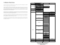
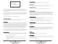
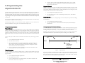
AquaController III
Owner's Manual
Version 3.20
© Neptune Systems
6288 San Ignacio Ave. #B
San Jose, CA 95139
Phone (408) 578-3022 • Fax (408) 578-9383
Table of Contents
TABLE OF CONTENTS ............................................................................................ 3
1. INTRODUCTION ................................................................................................... 7
SCOPE OF THIS DOCUMENT ............................................................................................................ 7
FEATURE LIST ................................................................................................................................. 7
2. GETTING STARTED ............................................................................................. 9
BASE UNIT INSTALLATION.............................................................................................................. 9
CONTROL INTERFACE INSTALLATION ............................................................................................ 9
ETHERNET INSTALLATION ............................................................................................................. 10
3. MENU OVERVIEW ................................................................................................ 13
RUN DISPLAY .................................................................................................................................. 16
CONTROL AND STATUS ................................................................................................................... 17
Feed Cycle
17
Manual Control
17
Power Fail Log
18
Power Log
18
Reset Power Log
18
DATA LOGGING.............................................................................................................................. 18
Print Data Log
Error
! Bookmark not defined.
Display Data Log
18
Reset Data Log
18
Log Interval
18
SETUP .............................................................................................................................................. 18
Timer Setup
18
Clock Setup
18
Leap Seconds
19
Temperature Setup
19
pH Setup
19
ORP Setup
19
Net Setup
19
IP Address
19
Netmask
19
Gateway Address
19
Admin Login/Password
19
DNS IP Address/Alternate DNS IP Address
19
Restart
20
Display Password
20
Init Memory
20
SELF TEST ....................................................................................................................................... 20
pH Probe Installation
23
ORP Probe Installation
24
PROBE CALIBRATION...................................................................................................................... 24
Temperature Calibration
24
pH Calibration
25
ORP Calibration
25
5. PROGRAMMING THE AQUACONTROLLER III ............................................27
PROGRAMMING BASICS .................................................................................................................. 27
Timer Names
27
Timer Program
27
Repeat Interval
28
Feed Interval
28
TEMPERATURE CONTROLLER SETUP ............................................................................................. 28
Temperature Control Program
29
Fixed Temperature
29
Seasonal Temperature Variation
29
PH CONTROLLER SETUP ................................................................................................................. 30
pH Control Program
31
ORP CONTROLLER SETUP.............................................................................................................. 31
ORP Control Program
32
TIMED EVENTS SETUP.................................................................................................................... 32
Timed Lighting
32
Timed Pumps
33
Repetitive and Random Events
34
Seasonal Lighting Variation
34
Simulating the Moon Cycle
35
Feed Cycle Timer Events
35
Externally Switched Events
36
Alarms
36
Hysteresis
37
Timer State Statements
38
ADVANCED PROGRAMMING........................................................................................................... 38
Statement Evaluation Order
38
6.OTHER CONNECTORS ........................................................................................39
SERIAL PORT INTERFACE ............................................................................................................... 39
Serial Connector Pinout
39
Telnet Commands
39
INPUT/OUTPUT CONNECTOR ........................................................................................................ 40
Input Connector Pinout
40
APPENDIX A - TROUBLE SHOOTING .................................................................43
APPENDIX B - SAMPLE PROGRAMS.....................................................................44
DEFAULT TIMER NAMES ................................................................................................................ 44
DEFAULT PROGRAM ....................................................................................................................... 44
4. PROBE INSTALLATION AND CALIBRATION ............................................... 23
PROBE INSTALLATION .................................................................................................................... 23
Temperature Probe Installation
23
AquaController III Owner’s Manual V3.00
Copyright 2005 - Neptune Systems
All rights reserved
AquaController III Owner’s Manual V3.00
Copyright 2005 - Neptune Systems
All rights reserved
This page intentionally left blank.
AquaController III Owner’s Manual V3.00
Copyright 2005 - Neptune Systems
All rights reserved
1. Introduction
Scope of this Document
Congratulations, you have just purchased the most advanced aquarium controller on the market! It is
recommended that you completely read the Owner's Manual before proceeding to set up the AquaController III
to perform any task.
Feature List
The following features are fully supported in the AquaController III base unit.
•
•
•
•
•
•
•
•
•
•
•
•
•
•
•
•
•
•
•
•
1
Chapter
Lighting Control
Wave Maker
Simulated Moon Cycle
Seasonal Lighting Variation
Seasonal Temperature Variation
4 External Switch Inputs
Temperature Monitor and Control
pH Monitor and Control
ORP Monitor and Control or second pH probe Monitoring/Control
Flash Memory for Easy Firmware Upgrades
Data Logging
RS232 Computer Interface
Ethernet Interface
Telnet Server
HTTP Server
Email Alarm Notification
Local Alarms
Simple Yet Sophisticated Programming Language
2 Lines by 16 Character backlit LCD Display
Built in Self Test
7
AquaController III Owner’s Manual V3.20
Copyright 2006 - Neptune Systems
All rights reserved
2
Chapter
with the RJ11 connectors (phone cable) into the Control Interface and the other end into the AquaController III.
Ethernet Installation
2. Getting Started
The AquaController III has an embedded 10 base T RJ45 Ethernet connector. A CAT 5 or CAT 6 cable should
be used to connect the AquaController to an Ethernet Hub or switch. The default network configuration settings
are shown below:
Base Unit Installation
Configuration Setting
The following figure points out all the connectors located on the side of the AquaController III. Please refer to it
during installation.
Power Backup Ethernet
9V DC 9V DC RJ45
Cntl
RJ11
Figure 1:
Serial
MDin 8
I/O
MDin 8
Temp
ORP/pH2
BNC
pH
BNC
IP Address
Default Value
192.168.1.50
Netmask
255.255.255.0
Gateway Address
192.168.1.1
Primary DNS
192.168.1.1
Alt DNS
192.168.1.1
AquaController III Connectors
The AquaController III should be installed in a dry environment which has little chance of getting wet. The
AquaController III is a sensitive piece of electronic equipment and is not water proof. Ideally, it should be located
several feet from the aquarium. Velcro strips with adhesive backing can be used to install the controller in its
permanent location.
In the event of a power outage the internal battery will maintain the internal state of the unit and allow for the
resumption of control of the aquarium as soon as power returns. It should be noted that no state changes will
occur in the external control modules during a power outage. After power is returned, all controlled devices will
be in the correct state within the Repeat Interval. The default interval is 5 minutes. See section ‘Repeat Interval’
on page 28 for more details on modifying the Repeat Interval.
The 9V-DC power adapter should be plugged into a 120V wall socket and the plug on the end of the cable
should be connected to the power connector on the AquaController III. Refer to the above figure for the
location of the connector.
Powerheads and pumps switching on and off generate power spikes which can damage electronic equipment.
The AquaController III has protection circuitry in the base unit, however, it is recommended as an added safety
precaution to plug the controller in a 'clean' AC socket. Power strips with transient suppression circuitry can be
used to make a 'clean' socket and to prevent power surges from damaging the AquaController III. Coil up all
power cords to reduce the amount radiate electrical noise.
It is quite likely that the defaults need to be modified to match your network settings. The network setup menu is
located in the Setup->Net Setup menu. First you need to get the settings for your local network – you can do this
by bringing up a command shell on your PC (type cmd in the start->run window of your PC). In the cmd shell
type ‘ipconfig /all’ – This will display your internal IP address, netmask, default gateway, and dns server. Follow
the steps below to configure the AquaController’s Ethernet port
1.
Connect the Ethernet cable between the AquaController's Ethernet port and your
router/hub/switch's Ethernet port. If the connection is good both the green and yellow
LEDs on the AquaController's Ethernet connector should lite. The green LED will blink
when there is network traffic.
2.
Enter the netmask, default gateway, and dns server into the AquaController’s network setup
menus. This information is entered in the setup->net setup menu on the AquaController 3.
The IP address should be unique and different then your PCs – most likely you’ll only change
the last 3 digits of the address. For example if your computers IP address is 192.168.1.101,
then set the AquaController's IP address to 192.168.1.50.
3.
Power cycle or restart (setup->netsetup->restart) the AquaController.
4.
The controller is accessed through your internet browser by typing in the IP address of the
controller in the address field of your browser. In the above example you would use
192.168.1.50.
Once that works then you can configure your router so that the AquaController can be accessed from the
internet. Follow these steps:
Direct Connect Installation
If Direct Connect boxes are used for control, follow the instructions included with the DC4, DC4HD or DC8.
Control Interface Installation
Simply plug the control interface into the wall outlet located close to the AquaController III and aquarium. It may
be necessary to use one or more power strips if multiple devices are to be controlled. Plug one end of the cable
9
AquaController III Owner’s Manual V3.20
Copyright 2006 - Neptune Systems
All rights reserved
1.
Configure your router so that WAN side port 80 tcp requests are sent to the AquaController's
IP address on port 80 (External port is 80, internal port is 80, and the internal IP address is the
AquaController's). This configuration is usually done in the router's virtual server setup menu,
port forwarding, or the UPnP section of the router. Consult the routers manual for details.
Note that some routers (Linksys) have global enables for UPnP or port forwarding, so be sure
to turn this on or your router will not forward port 80 to the AquaController.
10
AquaController III Owner’s Manual V3.20
Copyright 2006 - Neptune Systems
All rights reserved
2.
Change the administrator user name and password of the AquaController. See setup>netsetup on the controller.
3.
To access the controller from the internet you need to know your WAN IP address; the
WAN IP address can be found by going to www.whatismyip.com. This is the IP address that
will be entered into the address field of your browser when trying to access the controller from
the internet. If your internet connection has dynamic IP address, then sign up for a free
account at www.dyndns.org and following the installation instructions. The dyndns account
will allow access your controller using a consistent DNS name even though the IP address
may change. Note that some routers (DLink for example), have built-in support for dyndns
accounts so no client PC software is required.
This page intentionally left blank.
Note: Some ISPs block incoming port 80 requests, so you you will have to use a different external port number.
In this case you would configure your router to route a different incoming port like 4567 (or any other 4 digit
number) to port 80 of the AquaController's IP address. If this is the case in your router's port forwarding, or
UPnP section configure the external port would be 4567, internal port 80, and the internal IP address of the
AquaController. If your isp blocks port 80 then you would need to enter the address as
http://123.45.67.111:4567 - substitute your internet IP address for 123.45.67.111.
11
AquaController III Owner’s Manual V3.20
Copyright 2006 - Neptune Systems
All rights reserved
12
AquaController III Owner’s Manual V3.20
Copyright 2006 - Neptune Systems
All rights reserved
3. Menu Overview
The options and menus in the controller may seem overwhelming at first, but after a little practice you will find
that they are arranged in a logical and consistent manner.
All menus and sub-menus follow the same user interface. The Up and Down buttons move the arrow cursor up
and down. When the cursor reaches the bottom entry and the down button is pressed again, the menu items
scroll as expected. Similarly, if the cursor is at the top and the up button is pressed, the menu items scroll. The
Select button activates the current menu entry pointed to by the cursor. The activation will execute a command,
bring up another menu, or exit the current menu.
Root Level
Run
Control & Status
Data Log
The menu choices are in a circularly linked list, so repeated presses of the Up (or Down) button will cycle through
all the choices. Common to all menus is the Exit entry. When Exit is selected, the current sub-menu pops up and
control is returned to the previous (next higher) level menu.
3
2nd Level
Chapter
3rd Level
Feed
Manual Cntl
Power Fail Log
Power Log
Reset Power Log
Display Lock
Print Data Log
Display Log (T, pH, ORP)
Display Log (Oxy, Cond)
Reset Data Log
Log Interval
Timer Names
To make it easier to enter data into the AquaController III, all three of the buttons have an auto repeat function.
When any button is pressed for greater than 3/4 of a second, the current action begins to repeat. If the button is
pressed an additional 1 second, the auto repeat rate increases.
4th Level
Timer Setup
Timer Program
Modify Name
Add Name
Delete Name
Modify State
Add State
Delete State
Repeat Interval
Feed Interval
For quick reference the following table lists all of the menus and commands available to the AquaController III.
On the left side of the table are the root menu entries. Entries in the 2nd through 4th columns are sub-menus of
the column to the left of it.
Clock Setup
Tank Time Set
Leap Second
pH Calibration
pH2 Calibration
pH Setup
pH: On/Off
pH2 On/Off:
pH Temp Comp:
Temp Calibration
Temp Setup
Temp: On/Off
Temp Celsius
Temp Fahrenheit
Setup
ORP Calibrate
ORP Setup
ORP: On/Off
ORP pH Comp:
Net Setup
IP Address
Netmask
Root Level
Gateway
Admin Login
Admin Password
DNS Server
Alt DNS Server
3rd Level
Email Setup
2nd Level
14
AquaController III Owner’s Manual V3.20
Copyright 2006 - Neptune Systems
All rights reserved
4th Level
Email: ON/OFF
SMTP Server
Email From
Email To
Email ALM
ReEmail Delay
Email Test
Restart
Display Password
Init Memory
Run Display
The Run Display indicates the date, system time, temperature (temp), pH, and ORP. During most of the
AquaController III operation this will be the active display. If no input occurs (button selection) the LCD screen
will automatically return to this display. It can be selected by pressing the Select (right) button when the arrow
cursor is pointing at RUN.
Jan 10 8:10:30
Figure 2:
Run Display (Clock)
The above two diagrams show a typical display and assume that temperature, pH, and ORP are enabled. In
Figure 2 the first line displays the date (month day year) followed by the tank time (hour:minute:second). The
second line indicates the current status of the control modules; the first character represents the status of the first
timer name, the second character represents the status of the second timer name and so on. If the character
displayed is either an "M" or "m" then that timer is in manual mode (operation). The "M" indicates that the
controlled device is operating and the "m" indicates the device is idle. Manual Mode Operation is described in
section ‘Control and Status’ on page 17. The ‘U’ character indicates that the state of the controlled devices is
undefined. The undefined state can be entered in two ways.
1.
The controller has not yet evaluated the timer name.
2.
The program statements create a circular loop, and the controller state is not defined.
3.
None of the program statements has ever been true.
The other special characters displayed on this line indicate that the timer is in Automatic mode, and the controlled
device(s) are either "on" or "off". The character that is displayed for a particular timer is programmed in the
'Setup:Timer Setup:Timer Names' sub-menu. The following table shows the special characters (the first column
represents on and the second off):
Typically Lights
Typically Heater/Chiller
Typically Pumps/Powerheads
Other Controlled Devices
Figure 4: Run Display Special Characters
15
AquaController III Owner’s Manual V3.20
Copyright 2006 - Neptune Systems
All rights reserved
16
AquaController III Owner’s Manual V3.20
Copyright 2006 - Neptune Systems
All rights reserved
Power Fail Log
Temp pH ORP
78.3 8.34 382mV
The power fail menu allows you to display the last power failure and reset the power failure log.
Power Log
Selecting the power log menu display the last power failure time/date and the power restored time/date of the
last power interruption. If ‘none’ is in the power failed entry then no power failure has occurred.
Figure 3:
Run Display (Monitored Probes)
The UP button is used to toggle between the Clock Display and the Monitored Probes display. The first and
second line of the Monitored Probes display shows temperature (°F or °C), pH and ORP (millivolts). If a probe
expansion box is installed (PX1000), then the additional probes are displayed by pressing the UP button to toggle
the displayed probe display.
Pressing the Down button while the Run Display is active will initiate a Feed Cycle. During the Feed Cycle the
display will show a countdown of the number of seconds remaining. The Run Display is resumed following the
completion of the Feed Cycle. The Select button can be used to end the Feed Cycle early. See section ‘Feed Cycle’
on page 17 for more details.
To exit the Run Display and enter the root level menu press the Select button.
Reset Power Log
Activating this menu entry will reset the power failure and power restored time/date entries to ‘None’.
Data Logging
Data logging is a powerful feature which enables accurate tracking and recording of the conditions in the
aquarium. There are many possible uses for the data, some of which include analysis to help find cause and effect
relationships, trends which may foreshadow potential problems, and monitor the tank conditions necessary to
induce fish or coral spawning. The AquaController III’s internal memory can hold up to 600 data logs. This size
log buffer is enough to hold hourly data logs for four weeks. When the data log exceeds 600 entries, the oldest log
entry is replaced by the newest log entry.
Display Data Log
The Display Data Log menu allows you to scroll through the contents of the data log on the LCD screen. The
display data log menu displays the temperature, pH, and ORP values.
Control and Status
The control and status menu option allows the user to take any timer out of the automatic mode of operation
and force it to either an "on" or "off" state as well as viewing other operation status.
Feed Cycle
A special case of manual mode of operation is the Feed Cycle. This option allows the user to shut down certain
pumps, powerheads, etc. for a fixed period of time for the purpose of feeding the tank. To start a Feed Cycle
select the Feed Cycle entry in the Manual Control menu. When this mode is entered, the Feed Cycle controlled
modules are temporarily forced into the programmed state. The display shows a countdown of the number of
seconds remaining. When the count reaches zero, the Feed Cycle controlled modules return to normal operation.
The Feed Cycle can be interrupted early by pressing the Select button. See section ‘Feed Cycle Timer Events’ on
page 35 for instructions on how to program a timer to use a Feed Cycle and section ‘Feed Interval’ on page 28 on
how to change the Feed Cycle duration. After no key presses for 5 seconds the selected feed cycle will start.
To reduce the number of button presses required to initiate a Feed Cycle, a shortcut has been added to the Run
Display command. When the Run Display is active (see section ‘Run Display’ on page 16), the Down button can
be used to initiate a Feed Cycle, and then press the up or down buttons select which feed cycle (A to D) to start.
The initial display shows the earliest data entry and the Down button scrolls to a later data entry. The Up button
scrolls the display to an earlier data entry. To exit the Display Data Log menu press the Select button.
Reset Data Log
The Reset Data Log menu option clears the log memory in the AquaController III. NOTE: The data log is also
cleared if the tank time is changed or the log interval is modified. The 'r' reset command from telnet performs the
same function.
Log Interval
The Log Interval menu allows you to set how often the AquaController III logs a pH, ORP, or temperature
measurement to the data log. To modify select Log Interval and use the Up and Down buttons to advance to the
desired log interval. When displayed press the Select button. Sixty minutes is the default setting for log interval.
NOTE: The data log is cleared if the tank time is changed or the log interval is modified.
Setup
Manual Control
The manual timer menu allows you to place a control module out of Automatic Mode and turn it continuously
"on" or continuously "off". The following procedure is used to modify the on, off or automatic status of a timer:
Timer Setup
The timer setup and programming instructions are described in chapter 5 on page 27
1.
Go to the Control & Status:Manual Control menu.
Clock Setup
2.
Use the Up and Down buttons to locate the desired timer. When the cursor points to the
desired timer press the Select button.
3.
The underline cursor should now be under the ON, OFF, or AUTO status of the timer. Use
the Up and Down buttons to scroll to the desired state. Press the Select button to complete
the operation.
The tank clock keeps track of the time in the tank and is the main clock used by the timer program to turn off or
on the desired modules. The time clock is only included as a convenience to the user. The clock can be set by
following the directions listed below:
17
AquaController III Owner’s Manual V3.20
Copyright 2006 - Neptune Systems
All rights reserved
1.
Go to the Setup:Clock Setup:
18
AquaController III Owner’s Manual V3.20
Copyright 2006 - Neptune Systems
All rights reserved
2.
Select either Set Tank Time from the menu depending on which clock needs to be set.
3.
Use the Up and Down buttons to adjust the selected field to the desired value. When the value
is correct use the Select button to advance to the next field. Repeat until all time values are
entered.
Leap Seconds
The Leap Seconds allows the user to fine tune the accuracy of the clocks used in the AquaController III. The
number programmed into the AquaController III indicates how many seconds to adjust the internal clock per
day. For example if the clock is gaining 1.5 seconds per day, a value of -1.5 would be entered to offset this
inaccuracy. The AquaController III uses this value to slow its time down by 1.5 seconds each day. To modify this
entry, select Leap Seconds and use the Up and Down buttons to scroll to the desired Leap Seconds value. When
displayed press the Select button.
Temperature Setup
Temperature setup and probe installation are described in section ‘Temperature Probe Installation’ on page 23
and ‘Temperature Calibration’ on page 24.
pH Setup
pH setup and probe installation are described in section ‘pH Probe Installation’ on page 23 and ‘pH Calibration’
on page 25.
ORP Setup
ORP setup and probe installation are described in section ‘ORP Probe Installation’ on page 24 and ‘ORP
Calibration’ on page 25.
the correct DNS and alternate DNS IP address, and enter into this field. To change the address press the select
button advance to the next 3 digit address field. The up button increments the numeric field, and the down
button decrements it.
Restart
Any changes to the network fields do not take place until the controller is restarted. This menu entry allows the
controller to be reboot without having to power cycle it. Note: A restart will erase any data logs residing in the
controller.
Display Password
This menu allows for the changing of the password used if the display lock feature is turned on. The default
password is lower case ‘xyz’. The space character is used to terminate the entry of password if less than a four
character entry is desired.
Init Memory
Init All will initialize the AquaController III’s memory with the default program and calibration constants. Init
Program will only initialize the program and timers to the default program which can be found in Appendix B.
Self Test
The Self Test feature of the AquaController III performs a short diagnostic on the major internal components in
the base unit. If the Self Test is selected and the unit is operating correctly, a "passed" message is displayed on the
screen. The other information displayed indicates the date and revision of the AquaController III firmware as
well as the controller's serial number.
Net Setup
This menu allows for the setup of all configuration settings associated with the Ethernet port.
IP Address
The default IP address is 192.168.1.50. To change the address press the select button advance to the next 3 digit
address field. The up button increments the numeric field, and the down button decrements it.
Netmask
The default netmask is 255.255.255.0 (Class C network). To change the netmask press the select advance to the
next 3 digit mask field. The up button increments the numeric field, and the down button decrements it.
Gateway Address
The default gateway address is 192.168.1.1. If access outside your local network is required then this address
should be set to gateway IP address (typically your cable or DSL modem). To change the address press the select
button advance to the next 3 digit address field. The up button increments the numeric field, and the down
button decrements it.
Admin Login/Password
The default admin login and password is ‘admin’ and ‘1234’ respectively. This menu allows for the telnet, and
web pages to be login and password protected. If the controller is accessible from the internet, it is highly
recommended that the login and password fields are set to secure values.
DNS IP Address/Alternate DNS IP Address
The DNS IP address must be setup if the email alarm features of the controller are desired. Consult you ISP for
19
AquaController III Owner’s Manual V3.20
Copyright 2006 - Neptune Systems
All rights reserved
20
AquaController III Owner’s Manual V3.20
Copyright 2006 - Neptune Systems
All rights reserved
This page intentionally left blank.
21
AquaController III Owner’s Manual V3.20
Copyright 2006 - Neptune Systems
All rights reserved
4. Probe Installation and
Calibration
Probe Installation
Temperature Probe Installation
Before installing the temperature probe in the aquarium, the probe should be rinsed under tap water to make sure
that it is clean. Route the cable from the location of the AquaController III to the aquarium or the sump. It
should be installed in a vertical position where there is adequate water flow.
The AquaController III must be informed that a temperature probe has been installed. To enable the
temperature probe go to the Setup:Temp Setup menu and select ‘Temp On’
To remove Temperature from the AquaController III display, follow the above procedure and instead select
Temp Off.
If a probe expansion box which has temperature probes is used with the controller, then the additional
temperature probe are also enabled in the above menu. The first probe expansion boxes temperature probe is
name TMPA, and second expansion box’s temperature probe is TMPB, and so on.
If a probe expansion box which has pH probes is used with the controller, then the pH probes are also enabled
in the above menu. The first probe expansion boxes pH probe is name pHA1, the second pH probe of the
same expansion box is pHA2, and second expansion box’s pH probe is pHB1, and so on.
ORP Probe Installation
The plastic cap on the end of the probe should be removed before it can be used. Once the protective cap has
been removed the probe must be kept wet at all times. Failure to do so will result in damage to the probe. If the
probe is to be stored for some period of time, place pH=4.0 calibration solution into the protective cap before
placing it on the end of the probe.
Before installing in the aquarium the probe should be rinsed of any white residue under warm tap water and then
installed in a vertical position in the aquarium or sump where there is adequate water flow. The pH and ORP
probes should be placed at least 6 inches apart.
Route the coax cable to the location of the AquaController III. Attach the BNC connector on the cable to the
ORP BNC input of the AquaController III. Refer to figure 1 for the position of the ORP BNC input on the
AquaController III. Turn the BNC connector 1/4 turn clockwise to lock it firmly into place.
The AquaController III must be informed that an ORP probe has been installed. This is accomplished by
following this procedure:
1.
Go to the Setup:ORP Setup menu.
2.
Select ORP On
3.
Go to the Run menu at the top level. The ORP label and its current reading should be on the
display.
pH Probe Installation
To remove ORP from the AquaController III display, follow the above procedure and instead select ORP Off in
step 2.
The rubber cap on the end of the probe should be removed before it can be used. Once the protective cap has
been removed the probe must be kept wet at all times. Failure to do so will result in damage to the probe. If the
probe is to be stored for some period of time, place pH=4.0 calibration solution into the protective cap before
placing it on the end of the probe.
If a probe expansion box which has ORP probes is used with the controller, then the additional ORP probes are
also enabled in the above menu. The first probe expansion boxes ORP probe is name ORPA, and second
expansion box’s ORP probe is ORPB, and so on.
Before installing the probe in the aquarium, it should be rinsed of any white residue under warm tap water and
then installed in a vertical position in the aquarium or sump where there is adequate water flow. The pH and
ORP probes should be placed at least 6 inches away from each other.
Probe Calibration
Route the coax cable to the location of the AquaController III. Attach the BNC connector on the cable to the
pH BNC input of the AquaController III. Refer to figure 1 for the position of the pH BNC input on the
AquaController III. Turn the BNC connector 1/4 turn clockwise to lock it firmly into place.
Temperature Calibration
If a second pH probe is to be used with the AquaController 3, enable it in the pH setup menu. The second pH
probe plugs into the AquaController’s ORP connector. Note that only an ORP probe or a second pH probe can
be used at the same time (not both).
The AquaController III must be informed that a pH probe has been installed. This is accomplished by the
following procedure:
Calibration of the AquaController III is quite simple, and should be checked at regular maintenance intervals to
insure accurate operation.
It is not necessary to calibrate the temperature probe of the AquaController III. It has been properly calibrated at
the factory to maintain accurate temperature readings for the lifetime of the probe. However, it is possible to
make small adjustments to the displayed temperature so that it may be more closely correlated with another
temperature monitor. The following procedure should be used:
1.
Note the amount that the temperature needs to be adjusted either up or down. For example, if
the AquaController III temperature reads 77.4 °F and the reference thermometer reads 77.0
°F, an offset of -0.4 °F should be added to the AquaController III temperature.
1.
Go to the Setup:pH Setup menu.
2.
Go to the Setup:Temp Setup:Temp Calibration menu.
2.
Select pH On
3.
3.
Go to the Run menu at the top level. The pH label and its current reading should be on the
display.
Use the Up/Down buttons to enter the desired offset, which is -0.4°F in the above example.
When finished push the Select button.
To remove pH from the AquaController III display, follow the above procedure and instead select pH Off in
step 2.
24
AquaController III Owner’s Manual V3.20
Copyright 2006 - Neptune Systems
All rights reserved
4.
Go to the Run menu and now the temperature should match the reference. If not, go back to
step 1 and try again.
pH Calibration
Because of the variability in pH probes and the fact that they change over time, it is best to calibrate the
AquaController III pH circuitry. A two point calibration scheme is used to obtain the good results. For the most
accurate results it is best to use pH 7.00 and 10.00 solutions for salt water and pH 4.00 and 7.00 for fresh water.
The following procedure outlines the steps necessary:
1.
Go to the Setup:pH Setup menu. Enable or disable temperature compensation depending
upon your requirements.
2.
Select the pH Calibrate menu.
3.
Use the Up and Down buttons to select the lowest valued calibration solution. In order for the
calibration procedure to work correctly the low valued calibration must be used first.
4.
Place the pH probe into lowest valued calibration solution. Wait for the numbers on the
bottom of the LCD screen to stop changing. It does not matter what value is displayed only
that it is not changing. When the display stops changing press the select button.
5.
Rinse the probe in room temperature tap water.
6.
Use the Up and Down buttons to select the high valued calibration solution. Press the select
button when the correct value is displayed.
7.
Place the pH probe into high valued calibration solution. Wait for the numbers on the bottom
of the LCD screen to stop changing. When the display stops changing press the select button.
8.
The pH probe should now be properly calibrated.
ORP Calibration
It is not necessary to calibrate the ORP probe of the AquaController III. It has been properly calibrated at the
factory to maintain accurate ORP readings for the lifetime of the controller. However, it is possible to calibrate
the probe if so desired. Quinhydrone, pH 4.00 and pH 7.00 calibration solutions are required for the calibration.
The following procedure should be used to calibrate the ORP:
1.
Create a saturated solution of Quinhydrone and pH 7.00 calibration solution.
2.
Select Setup:ORP Setup:ORP Calibrate from the AquaController III’s menus.
3.
Place the ORP probe into the Quin-7.00 solution. Wait for the numbers on the bottom of the
LCD screen to stop changing. It does not matter what value is displayed only that it is not
changing. When the display stops changing press the select button.
4.
Create a saturated solution of Quinhydrone and pH 4.00 calibration solution.
5.
Place the ORP probe into the Quin-4.00 solution. Wait for the numbers on the bottom of the
LCD screen to stop changing. It does not matter what value is displayed only that it is not
changing. When the display stops changing press the select button.
6.
The ORP probe is now calibrated.
25
AquaController III Owner’s Manual V3.20
Copyright 2006 - Neptune Systems
All rights reserved
4.
5. Programming the
AquaController III
The AquaController III comes equipped with a simple yet powerful programming language which enables it to
perform the normal aquarium control tasks as well as many tasks which are impossible to perform on a
conventional controller. All program statements are entered through the three button user interface of the base
controller unit and follow the same user interface as the menu navigation commands. The Up and Down buttons
navigate through the various options of the fields. The Select button advances to the next field or completes the
command entry.
The program and configuration information input are stored in the AquaController III's non-volatile memory.
Power failures do not affect the contents of this memory.
The default program installed in the AquaController III is listed in Appendix A. Most users will only have to
make minor modifications to this program to control and monitor their aquatic system.
Programming Basics
Timer Names
The first step in setting up the AquaController III for any type of control is deciding which communication
channel is to be used for a controlled device. It does not matter which channel is used, only that it is unique for
each device in the household. For example, one control module is to be used to control the heater in the
aquarium. The description name HET^ is chosen for the timer name, and it is assigned the communication ID
of A1. Make sure that the control modules communications ID matches the ID that is associated with the Timer
Name.
Repeat Interval
The Repeat Interval defines how often the AquaController III retransmits commands to the remote control
modules. The commands are repeated on a periodic basis to ensure that all of the control modules are in the
correct state. The default setting for Repeat Interval is 5 minutes and should not have to be changed by you. The
following procedure is used if you chose to modify this parameter:
1.
Go to the Setup:Timer Setup:Repeat Interval menu.
2.
Use the Up/Down buttons to enter the desired Repeat Interval (minutes). When finished
push the Select button.
Feed Interval
The Feed Interval menu allows you to change the length of time for a Feed Cycle. The procedure for modifying
it is described below:
1.
Go to the Setup:Timer Setup:Feed Interval menu.
2.
Use the Up/Down buttons to enter the desired feed interval (minutes). When finished push
the Select button.
Temperature Controller Setup
For the successful aquarium, it is very important to maintain an accurate and stable temperature throughout the
day. Large fluctuations in temperature can result in the loss of aquatic life. The AquaController III is capable of
controlling the temperature very accurately (+- .3 °F), since it continuously monitors the environment.
Depending on the external conditions both a heater and chiller may be necessary to maintain a stable temperature
for the aquarium inhabitants. The AquaController III is capable of controlling a heater, a chiller, or both.
Turn Heater
On
To program the AquaController III with this communication ID and Timer Name, the following procedure is
used:
1.
Go to the Setup:Timer Setup:Timer Names menu.
2.
Select Add Name from the menu.
3.
Input a 4 character descriptive name for this timer channel (HET^ in the above example). Use
the Up and Down buttons to scroll through the alphabet and the Select button to advance to
the next character. The fourth character entered is special in that it is displayed on the Run
screen to indicate that status of the controlled device.
4.
Input the communications ID letter and number next. These letters and numbers should
match channel IDs set on the control module earlier.
Timer Program
The AquaController III uses a simple programming language to control the external modules. The program
statements are input through the three button interface. The procedure below illustrates how to input a typical
program statement:
1.
Go to the Setup:Timer Setup:Timer Program menu.
2.
Select ‘Add State’ from the menu.
3.
Use the Up and Down buttons to locate the desired token (word). When it is displayed use the
Select button to advance to the next input field.
Continue to input the control statements until finished by jumping back to step 2. If a mistake
is made entering a statement, the Modify State command from the Setup:Timer Setup:Timer
Program can be used to correct it.
Turn Chiller
On
Cold
Hot
Desired
Temperature
Heater and
Chiller Off
Figure 5:
Temperature Scale
The above figure illustrates the mechanism which is used to maintain the temperature. When the temperature
drops below a preset value, the heater is turned on and when the temperature rises to the desired temperature, the
heater is shut off. Likewise when the temperature exceeds the preset high value, the chiller is turned on and when
the temperature falls to the desired temperature, the chiller is shut off.
28
AquaController III Owner’s Manual V3.20
Copyright 2006 - Neptune Systems
All rights reserved
Temperature Control Program
Fixed Temperature
May
June
July
August
September
October
November
December
Suppose that the desired temperature of the aquarium is 77 °F. The heater should be enabled if the temperature
falls below 76.7 °F, and disabled when the aquarium reaches the desired 77 °F. Likewise the chiller should be
enabled if the temperature rises above 77.3 °F, and disabled when the temperature reaches the desired 77 °F. It is
recommended that the high and low set points be at least 0.3°F from the desired temperature.
For the heater control described above the following code produces the desired result assuming that the heater
timer name is 'HET^':
76.5
77.5
78.5
80.5
78.5
77.5
76.5
76.0
To illustrate how to use this advanced feature for heater control, refer to the following program:
If Temp < 76.7
Then HET^ ON
If Temp > 77.0
If Temp < RT+-0.4
Then HET^ ON
If Temp > RT+0.0
Then HET^ OFF
For the chiller control described above the following code produces the desired result assuming that the chiller
timer name is 'COL^':
If Temp > 77.3
Then COL^ ON
If Temp < 77.0
The above statements turn the heater (HET) on if the tank temperature falls below the season temperature (RT)
of the day by more than 0.4 °F and shuts the heater off when the tank temperature exceeds the season
temperature (RT). For chiller control a similar program is used and is illustrated below:
If Temp > RT+0.4
Then COL^ OFF
Then COL^ ON
If Temp < RT+0.0
If the aquarium only has a heater, it is necessary to only enter the heater portion of the control program shown
above. Conversely, if only a chiller is to be used, then the chiller portion of the control is all that is necessary to
enter into the AquaController III.
If a probe expansion box is used, the first expansion temperature probe is referenced as TmpA, and the second
expansion box’s temperature probe is referenced as TmpB, and so on.
NOTE: The default factory setting comes with the HET^ and COL^ timer names already installed to ease the
initial setup. Choose the ‘Modify Name’ command from the Setup:Timer Setup:Timer Name menu to modify
the names and channel IDs. Also the ‘Delete Name’ can be used to remove unwanted names.
NOTE: The default factory setting comes with generic heater and chiller programs already installed to ease the
initial setup. Choose the ‘Modify State’ command from the Setup:Timer Setup:Timer Program menu to modify
the temperatures. Also the ‘Delete State’ can be used to remove unwanted statements.
Seasonal Temperature Variation
One of the AquaController III’s more advanced features is its ability to simulate the varying temperatures during
the seasons of the year. The following table lists the default temperatures for the first of each month. On days
other than the first the temperatures are interpolated with the current and next month values.
Month
January
February
March
April
Then HET^ OFF
Then COL^ OFF
The first program statement turns on the chiller (COL) when the tank temperature exceeds the seasonal
temperature (RT) by 0.4 °F and shuts the heater off when the tank temperature is below the seasonal temperature
(RT).
If a probe expansion box is used, the first expansion temperature probe is referenced as TmpA, and the second
expansion box’s temperature probe is referenced as TmpB, and so on.
pH Controller Setup
pH is perhaps one of the most critical parameters to maintaining successful aquariums. Many reef aquariums
which are heavily stocked with stony corals require large additions of kalkwasser on a continuous basis. The large
additions of kalkwasser can result in the pH rising too high. To counter the high pH, CO2 is injected into the
aquarium. However, the pH must be monitored closely when CO2 is injected so that the pH does not dip too
low. The injection is difficult if not impossible to do adequately by hand. This task is ideally suited for the
AquaController III, since it continuously monitors the pH and can enable /disable CO2 injection at the
appropriate times.
Temp (°F)
76.0
75.0
76.0
76.0
29
AquaController III Owner’s Manual V3.20
Copyright 2006 - Neptune Systems
All rights reserved
30
AquaController III Owner’s Manual V3.20
Copyright 2006 - Neptune Systems
All rights reserved
Turn ozone
Injection On
Turn CO2
Injection On
Higher
pH
Lower
pH
Lower
ORP
Desired ORP
Desired pH
Turn ozone
Injection Off
Turn CO2
Injection Off
Figure 6:
Higher
ORP
Figure 7:
pH Scale
ORP Scale
The above figure illustrates the mechanism which is used to maintain the pH. When the pH rises above a preset
level the CO2 injection is turned on, and when the pH falls to the desired value, the injection is shut off.
The above figure illustrates the mechanism which is used to maintain the ORP. When the ORP falls below a
preset level the ozone injection is turned on, and when the ORP rises to the desired value, the injection is shut
off.
pH Control Program
ORP Control Program
Suppose that the desired pH of the aquarium is 8.35, and the CO2 injector should be enabled if the pH rises
above 8.40. It is recommended that the high set point be at least 0.05 from the desired pH.
For the pH control described above the following code produces the desired result. The code assumes that the
CO2 injector timer name is 'CO2$':
Suppose that the desired ORP of the aquarium is 375 mV, and the ozone injector should be enabled if the ORP
falls below 365 mV. It is recommended that the low set point be at least 10 mV from the desired ORP.
For the ORP control described above the following code produces the desired result assuming that the ozone
injector timer name is 'OZN$':
If pH > 8.40
If ORP < 365
Then CO2$ ON
If pH < 8.35
Then OZN$ ON
If ORP > 375
Then CO2$ OFF
If a second pH probe is installed into the ORP probe of the AquaController III, it is referred to as pH2 in the
program statements. If a probe expansion box is used, the first expansion pH probe is referenced as pHA1, and
the second expansion box’s pH probe is referenced as pHB1, and so on.
NOTE: The default factory setting comes with the CO2$ timer name already installed to ease the initial setup.
Choose the Modify Name command from the Setup:Timer Setup:Timer Name menu to modify the name and
channel IDs. Also the Delete Name can be used to remove unwanted names.
NOTE: The default factory setting comes with a generic pH control program already installed to ease the initial
setup. Choose the Modify State command from the Setup:Timer Setup:Timer Program menu to modify the pH
set points. Also the Delete State can be used to remove unwanted statements.
Then OZN$ OFF
If a probe expansion box is used, the first expansion ORP probe is referenced as ORPA, and the second
expansion box’s ORP probe is referenced as ORPB, and so on.
NOTE: The default factory setting comes with the ozone timer name already installed to ease the initial setup.
Choose the Modify Name command from the Setup:Timer Setup:Timer Name menu to modify the name and
channel IDs. Also the Delete Name can be used to remove unwanted names.
NOTE: The default factory setting comes with a generic ORP control program already installed to ease the initial
setup. Choose the Modify State command from the Setup:Timer Setup:Timer Program menu to modify the
ORP set points. Also the Delete State can be used to remove unwanted statements.
Timed Events Setup
ORP Controller Setup
Oxidation Reduction Potential (ORP) is a good indicator of the water quality of the aquarium. ORP is a
measurement of the potential for chemical reactions in the aquarium. If it is too low the aquarium water contains
many organic carbons and the water can be toxic. Ozone is a highly reactive form of oxygen which can be
injected into the aquarium to reduce the amount dissolved organic carbons in the aquarium. It must be injected
carefully as too much can be lethal to the aquarium inhabitants. This task can be done easily by the
AquaController III since it continuously monitors the ORP and can enable and disable ozone injection at the
appropriate times.
31
AquaController III Owner’s Manual V3.20
Copyright 2006 - Neptune Systems
All rights reserved
The AquaController III can control such devices as lights, pumps, power-heads, and chemical dosing. The
AquaController III has an internal real time clock which can be used to enable/disable many control modules
throughout the day. The times programmed into the AquaController III are compared with the Tank Time clock.
The timed events capability is best illustrated through several examples.
Timed Lighting
Suppose that a reef aquarium has two independent lights which need to be turn on and off at appropriate times.
The first lighting system should come on at 8:30 AM and be turned off at 9:30 PM. The second lighting system
32
AquaController III Owner’s Manual V3.20
Copyright 2006 - Neptune Systems
All rights reserved
should come on at 9:30 AM and be turned off at 8:30 PM.
For the lighting control described above the following code produces the desired result. It assumes that the light
timer names are LT1* and LT2*. NOTE: The AquaController III time display is in 24 hour military format.
Repetitive and Random Events
Suppose that it is desired to have a power-head oscillate on for 20 minutes and off for 10 minutes, and another
power-head in the system should be randomly turned on for 1 to 10 minutes and off for 1 to 15 minutes.
The following AquaController III code will produce this effect:
If Time > 08:29
Then LT1* ON
If Time > 21:29
Then LT1* OFF
If Time > 09:29
Then LT2* ON
If Time > 20:29
Then LT2* OFF
NOTE: The default factory setting comes with the LT1* and LT2* timer names already installed to ease the
initial setup. Choose the Modify Name command from the Setup:Timer Setup:Timer Name menu to modify the
names and channel IDs. Also the Delete Name can be used to remove unwanted names.
NOTE: The default factory setting comes with generic lighting programs already installed to ease the initial setup.
Choose the Modify State command from the Setup:Timer Setup:Timer Program menu to modify the enabled
and disabled times. Also the Delete State can be used to remove unwanted statements.
OSC 20/10 ON/OFF
Then PM1% ON
RND 10/15 ON/OFF
Then PM2% ON
The abbreviations OSC and RND stand for oscillate and random respectively. The code assumes that powerhead 1's timer name is PM1% and power-head 2's timer name is PM2%. Refer to section ‘Programming Basics’
on page 27 for instructions on how to program the timer names and this code into the AquaController III.
The wave maker capability of the AquaController III can be used to create an alternating left to right and then
right to left current in the aquarium. This type of water motion can be accomplished by placing one powerhead
on the left side of the tank and one on the right side. The pump on the left is turned on for a fixed interval and
then shut off. Then the pump on the right is turned on for a fixed interval and then shut off. The following
program will produce this effect and assumes that the fixed interval is 20 minutes.
OSC 20/20 ON/OFF
Timed Pumps
The AquaController III can be used to simulate the tide in an aquarium. This can be accomplished by having two
power heads at opposite ends of the aquarium which could be alternately turned on and off.
The following AquaController III code will produce this effect:
Then PM1% ON
OSC 20/20 ON/OFF
Then PM2% OFF
If Time > 00:00
The only tricky part about the above code is that the ON or OFF value following the timer name (PM1% or
PM2%) determines what the initial condition of the pumps will be at power on. In the above example PM1% will
be on and PM2% will be off when the controller is first powered on.
Then PM1% OFF
If Time > 06:00
Seasonal Lighting Variation
Then PM1% ON
If Time > 12:00
Then PM1% OFF
If Time > 18:00
One of the AquaController IIIs more advanced features is its ability to simulate the varying lengths of daylight
during the seasons of the year. The following table lists the default sunrise and sunset times for the first of each
month. These times are based upon a typical tropical reef at 15° north latitude. On days other than the first the
sunrise and sunset times are interpolated.
Then PM1% ON
If Time > 00:00
Then PM2% ON
If Time > 06:00
Then PM2% OFF
If Time > 12:00
Then PM2% ON
If Time > 18:00
Then PM2% OFF
This program assumes that pump 1 (PM1%) and pump 2 (PM2%) are located on opposite ends of the aquarium.
Refer to section ‘Programming Basics’ on page 27 for instructions on how to program the timer names and this
code into the AquaController III.
33
AquaController III Owner’s Manual V3.20
Copyright 2006 - Neptune Systems
All rights reserved
Month
January
February
March
April
May
June
July
August
September
October
November
December
Sunrise
7:33
7:37
7:26
7:06
6:47
6:39
6:43
6:52
6:57
6:58
7:03
7:17
34
Sunset
18:51
19:07
19:17
19:21
19:25
19:34
19:41
19:38
19:21
18:59
18:41
18:38
AquaController III Owner’s Manual V3.20
Copyright 2006 - Neptune Systems
All rights reserved
To illustrate how to use this advanced feature, refer to the following program:
If Sun 000/000
Then LT1* ON
If Sun 060/-045
Then LT2* ON
The first statement turns on the first light (LT1) at sunrise of the particular day and off at sunset. The second
program statement turns on the second light (LT2) 60 minutes after sunrise and shuts it off 45 minutes before
sunset. By varying the sunrise and sunset offsets of various lights, it is possible to simulate the increasing intensity
of light at sunrise and the decreasing intensity at sunset.
Simulating the Moon Cycle
One of the AquaController III’s more advanced features is its ability to simulate the phases of the moon by
simulating both the moonrise and moonset as well as varying the intensity of the light source. The
AquaController III’s moonrise and moonset times match the true lunar cycle.
On days other than the first of the month, moonrise and moonset times are interpolated.
NOTE: Just like in the real world the moonrise and moonset are approximately 50 minutes later each day. So
during a new moon the moonrise is in the morning and the moonset is in the evening. During a full moon the
moonrise time is in the evening and the moonset time is in the morning. It is possible for the moon light to be on
during the day period.
Refer to section ‘Programming Basics’ on page 27 for instructions on how to program the timer names and this
code into the AquaController III.
Programming the length of the Feed Cycle time interval is described in section ‘Feed Interval’ on page 28. The
letter (A through D) following the Feed keyword specifies which feed timer to use. The number following the
Feed keyword specifies the number of minutes that the timer is to remain on/off following the completion of the
feed cycle count down. In the above example PM1 will turn back on at the end of the feed interval and PM2 will
turn on 5 minutes later.
To initiate a Feed Cycle select Manual Control:Feed menu item. Also pressing the Down button while the Run
Display (see section ‘Run Display’ on page 16) is active will initiate a Feed Cycle. The display should say Feed and
give a countdown of the number of seconds left. When the countdown has terminated the pumps will resume
normal operation. The Feed Cycle can be shortened or canceled by pressing the Select button during the
countdown.
Externally Switched Events
The AquaController III is capable of sensing whether or not an external switch is open or closed and uses that
information to operate a control module. The switch inputs are brought into the AquaController III by two pins
on the I/O connector (See section ‘Input/Output Connector’ on page 40 for a diagram).
One possible use for the external switch input is to monitor the water level in the sump. When the level is too
low, the float switch in the sump is open, and the AquaController III is informed that the water level is too low
via the external switch inputs. Typically, the make up water in reef tanks contains kalkwasser and the following
program example shows how kalkwasser addition could be implemented.
If Switch1 OPEN Then H2O ON
If Switch1 Closed Then H2O OFF
If pH > 8.30 Then H2O OFF
Max Change 010 M Then H2O OFF
To illustrate how to use this advanced feature, refer to the following program:
If Moon 000/000 Then MON* ON
Refer to section ‘Programming Basics’ on page 27 for instructions on how to program the timer names and this
code into the AquaController III.
The first statement turns on the first light (MON) at the moonrise of the particular day and off at the moonset.
The control module used to control the light source for the Moon cycle must be a lamp module so that the light
intensity can be varied. NOTE: Only use an incandescent light bulb for the moon light, not a fluorescent bulb.
Feed Cycle Timer Events
The AquaController III is capable of shutting off certain devices for a period of time and then resuming normal
operation. This behavior is desirable for the main pumps and powerheads in the aquarium during feed times.
With the pumps shut down floating food will not be washed into the surface skimmer before the fish have had a
chance to eat it.
The AquaController III must be told by programming which modules should be shut off during a feed cycle.
Suppose that there is one main pump and a powerhead in the system, and they should be shut off for 5 minutes
on a user initiated feed cycle. The following program will accomplish this:
If Time > 00:00 Then PM1% ON
OSC 20/10 ON/OFF Then PM2% ON
If FeedA 000 Then PM1% OFF
If FeedA 005 Then PM2% OFF
35
AquaController III Owner’s Manual V3.20
Copyright 2006 - Neptune Systems
All rights reserved
Notice that kalkwasser is only added to the tank if the pH is below 8.30. See section ‘Hysteresis’ on page 37 for a
description of the Max Change program statement. There are 2 digitals inputs on the AquaController III, so valid
Switch keywords are ‘Switch1’, and ‘Switch2’.
Alarms
The AquaController III is capable of signaling out of range conditions in the Aquarium. By using an Alarm
Module (CM506) or plugging a buzzer into a direct connect outlet, and the appropriate program setup in the
AquaController III, an audible tone can be signaled when the monitored conditions exceed a setpoint. The
program statements below describe how to setup the AquaController III for out of range conditions on pH,
ORP, and temperature.
First, add a timer name. Refer to section ‘Timer Names’ on page 27 for a detailed description on the procedure to
perform this task. For the example following the timer name is assumed to be ALM^ on channel A09. In
addition to making the alarm modules address match the address programmed into the AquaController III, the
switches on the Alarm module should be set to "Sounder Only" and "Continuous".
The following program statement makes OFF the default state for the ALM control module. If alarms are used,
this statement must be present.
If Time > 01:00 Then ALM^ OFF
The following program statements signal an alarm if the temperature is greater than 80.0 °F or less than 75.0 °F.
36
AquaController III Owner’s Manual V3.20
Copyright 2006 - Neptune Systems
All rights reserved
The alarm timer name is assumed to be ALM^:
If Temp > 80.0F Then ALM^ ON
If Temp < 75.0 Then ALM^ ON
The following program statements signal an alarm if the pH is greater than 8.5 or less than 7.9. The alarm timer
name is assumed to be ALM^:
If pH > 8.50 Then ALM^ ON
If pH < 7.90 Then ALM^ ON
The following program statements signal an alarm if the ORP is greater than 410mV or less than 300mV. The
alarm timer name is assumed to be ALM^:
If ORP > 410 Then ALM^ ON
If ORP < 300 Then ALM^ ON
The following program statements signal an alarm if the power has failed. The alarm timer name is assumed to be
ALM^:
If Power 000 Then ALM^ ON
The number after the Power keyword specifies the number of minutes after power is restored to keep the Power
statement true.
Some or all of the above alarm conditions may be programmed into the AquaController III. Refer to section
Timer Program on page 27 for the procedure to enter the above program statements into the AquaController
III's memory.
Hysteresis
The MAX Change timer command allows for timer channels to stay in a particular state for a minimum length of
time. This is useful when a control input (pH, temp, or ORP) may oscillate between two values which in turn
causes a pump, light, etc. to turn on and off over a very short period of time. For example suppose the following
program is used to control kalkwasser addition to a reef tank:
If Switch1 OPEN Then H2O ON
If Switch1 Closed Then H2O OFF
If pH > 8.30 Then H2O OFF
The 'Max Change' statement at the end of the program forces the H2O control module to remain in the off state
for a minimum of 10 minutes before being allowed to turn back on. The off state was chosen as the "sticky" state
so that H2O pump will not stay in the on state for a minimum of 10 minutes; in some systems this may add too
much water to the system. In general it is only necessary to use this command when there is single value of a
monitored parameter (pH, ORP, or Temp) which can cause the control module to turn both on and off.
Note: In order for either of the above two programs to operate correctly, the statements must be in the same
order as shown above. The AquaController III evaluates the program statements from top to bottom, and if the
'If pH >8.30' was executed first the desired operation would not be achieved.
Timer State Statements
The AquaController III adds a new timer evaluation statement which allows the state of another timer to activate
or deactivate a control module. The following example illustrates the use of this statement:
If Time > 08:00 Then LT1 ON
If Time > 20:00 Then LT1 OFF
OSC 010/015 M Then PM1 ON
If Timer LT1 = OFF Then PM1 OFF
These statements cause the pump PM1 to oscillate for 10 minutes on and then 15 minutes off. The Timer
statement causes the pump to be shut off if the light LT1 is off.
Advanced Programming
This section explains some of the complicated programming styles which are possible with the AquaController
III. Most users will not have to worry about these subtleties. If you attempt to program the AquaController III in
a non-standard way, experiment with the program on a non-critical sub-system of the tank. A buggy program
could be potentially dangerous to your tank's inhabitants.
Statement Evaluation Order
Most programs do not care which way program statements are entered, however there are some cases in which
order is important. The program statements are executed in the ordered listed by entering telnet command 'l'. The
one exception to this rule is program statements which start with 'If Time'. The 'If Time' statements are executed
first regardless of where they are located in the program code. This requirement is necessary due to the circular
nature of 'Time' type statements (i.e. the cycle repeats day after day). The execution order can also be displayed on
the LCD screen by selecting Modify State in Setup:Timer Setup:Timer Program:Timer and scrolling from first
statement to the last by pressing the Down button.
The goal of this program is to dose kalkwasser when the water level in the tank is low, and the pH value is not
too high. This program mostly works, except when the tank water level is low, and the pH value oscillates
between 8.30 and 8.31. In this case the H2O control module may turn on and off rapidly.
To alleviate this problem a hysteresis command is included in the AquaController III language. The 'MAX
change' command forces the control module to stay in a certain state for a minimum length of time before being
allowed to change. The minimum length of time can be specified for either the ON or OFF state but not both.
The following program corrects the potential problem:
If Switch1 OPEN Then H2O ON
If Switch1 Closed Then H2O OFF
If pH > 8.30 Then H2O OFF
Max Change 010 M Then H2O OFF
37
AquaController III Owner’s Manual V3.20
Copyright 2006 - Neptune Systems
All rights reserved
38
AquaController III Owner’s Manual V3.20
Copyright 2006 - Neptune Systems
All rights reserved
6. Other Connectors
Serial Port Interface
The serial port interface is reserved for future expansion.
r
The reset datalog will initialize the data log memory and set the number of log
entries to zero.
on XXX
This command puts device XXX in manual mode and turns it on. XXX is the
timer name. Example: on LT1
off XXX
This command puts device XXX in manual mode and turns it off. XXX is the
timer name. Example: off LT1
auto XXX
This command puts device XXX into automatic module. XXX is the timer name.
Example: auto LT1
Input/Output Connector
Serial Connector Pinout
Following is the pinout of the serial port. This diagram assumes that you are looking at the connector on the
AquaController III.
The input output connector allows the AquaController III to be directly receive additional digital input or to
control devices via a direct connection.
The 2 digitals inputs are TTL compatible with internal pull up resistor inside the AquaController III. The input
voltage must be limited to be between 0 and 5V. Voltages outside this range may result in permanent damage to
the AquaController III.
8
7
5
6
4
2
Input Connector Pinout
3
Following is the pinout of the input port (Minidin 8). This diagram assumes that you are looking at the connector
on the AquaController III.
1
8
Figure 10: Serial Port Connector
Pin Number
Description
1
Reserved
2
Reserved
3
Serial Transmit Data
4
Ground
5
Serial Receive Data
6
Ground
7
Reserved
8
Ground
Figure 11: Serial Port Signal Description
Telnet Commands
The following commands are available from the Ethernet telnet interface. They are all single letter commands
which are executed by typing the letter followed by a carriage return.
l
The list command will display all the defined timer names and program
statements. This command is useful in debugging the program used by the
AquaController III.
c
The current status command will display the current conditions in the aquarium.
It will also list the state of all the control modules.
d
The data log Command will print to the telnet port all the data logged by the
AquaController III.
7
5
6
4
2
3
1
Figure 12: Input/Output Port Connector
Pin Number
Description
1
Input #1
2
Input #2
3
Reserved
4
Reserved
5
Reserved
6
Reserved
7
Reserved
8
Ground
Figure 13: Input/Output Port Signal Description
Any dry contact switch can be connected to any of the AquaController’s digital inputs. No external voltage
source is required. One wire from the mechanical switch should connect to the ground pin (pin 8), and the other
40
AquaController III Owner’s Manual V3.20
Copyright 2006 - Neptune Systems
All rights reserved
wire from the switch should connect to one of the two digital inputs (pin 1, 2).
41
AquaController III Owner’s Manual V3.20
Copyright 2006 - Neptune Systems
All rights reserved
This page intentionally left blank.
42
AquaController III Owner’s Manual V3.20
Copyright 2006 - Neptune Systems
All rights reserved
Appendix A - Trouble Shooting
Problem
No Display.
Possible Cause
The base unit has no power.
The base unit control program is
hung.
Incorrect pH or ORP readings.
No control modules operating.
Some control modules do not
operate in both manual and auto
mode.
A control module does not
operate in auto mode.
Compact florescent lights turn on
when it is supposed to be off.
Every other controlled device
works correctly.
The probes are not correctly
calibrated.
The probes are old or defective.
There is s ground loop created by
a tank grounding probe and the
serial port.
The control interface module is
not connected to the base unit.
The control module and timer
name addresses are not the same.
The timer module is in manual
mode as indicated by an m or M
in the run screen.
The control program is incorrect.
The standard control modules
have a feature called local control,
which causes the control module
to turn on if the input impedance
changes.
Possible Solution
Make sure the AC adapter is installed
in the base unit and the wall socket
correctly.
Remove AC power from the
AquaController III for 10 seconds.
Reapply power and the
AquaController III will reset.
Calibrate the particular probe.
Replace the probe.
Remove the ground probe or the
serial port connection. Install a ground
isolated serial connector sold by
Neptune Systems (part # SERIPC9).
Attach the interface module to the
base unit.
Make the both addresses the same.
See section ‘Timer Names’ on page
27.
Put the timer in automatic mode. See
section ‘Manual Control’ on page 17.
Examine the timer control statements
for correctness.
Plug an additional load into the
control module controlling the lights.
Or
Disable local control in the control
module. Contact technical support for
details.
Appendix B - Sample Programs
The following default program is programmed into the non-volatile memory of the AquaController III. The
program has the capability to control 2 pumps, 2 lights, the pH level, the ORP level, and the temperature. The
current program and settings can be erased and the following default program loaded at anytime by selecting 'Init
Memory' from the 'Setup' menu.
Default Timer Names
The notes following the semicolon are comments and not part of the program.
LT1-A01
; Light 1 on Channel A01.
LT2-A02
; Light 2 on Channel A02.
PM1-A03
; Pump 1 on Channel A03.
PM2-A04
; Pump 2 on Channel A04.
HET-A05
; Heater on Channel A05.
COL-A06
; Chiller on Channel A06.
OZN-A07
; Ozone on Channel A07.
CO2-A08
; CO2 on Channel A08.
ALM-A09
; Alarm module on Channel A09
Default Program
The following program is the default program in the AquaController III's non-volatile memory. The notes
following the semicolon are comments and not part of the program.
If Time > 08:30 Then LT1 ON
If Time > 21:30 Then LT1 OFF
If Time > 09:30 Then LT2 ON
If Time > 20:30 Then LT2 OFF
If Temp > 77.0 Then COL ON
If Temp < 76.5 Then COL OFF
If Temp < 76.0 Then HET ON
If Temp > 76.5 Then HET OFF
OSC 010/010 ON/OFF Then PM1 ON
OSC 010/010 ON/OFF Then PM2 OFF
If Feed cycle Then PM1 OFF
If Feed cycle Then PM2 OFF
If ORP < 365 Then OZN ON
If ORP > 385 Then OZN OFF
If pH > 8.45 Then CO2 ON
44
AquaController III Owner’s Manual V3.20
Copyright 2006 - Neptune Systems
All rights reserved
Neptune Systems Limited Warranty
If pH < 8.35 Then CO2 OFF
If Time > 00:00 Then ALM OFF
If pH > 8.50 Then ALM ON
Neptune Systems warrants this product (excluding probes) to be free from defects in material and workmanship
for a period of 1 year from the date of purchase. Probes carry a 90-day warranty. If repair or adjustment is
necessary and has not been the result of abuse, misuse, or accidental damage, within the 1 year period, please
return the product with proof of purchase, and correction of the defect will be made without charge. Opening
the AquaController III base unit voids this warranty.
If pH < 8.00 Then ALM ON
If ORP > 450 Then ALM ON
If ORP < 300 Then ALM ON
If Temp < 75.0 Then ALM ON
For your protection, items being returned must be carefully packed to prevent damage in shipment and insured
against possible damage or loss. Neptune Systems will not be responsible for damage resulting from careless or
insufficient packaging. Before returning please obtain a return authorization (RMA) number from Neptune
Systems at (408) 578-3022. Returned merchandise will not be accepted without a RMA number.
If Temp > 78.0 Then ALM ON
Except for the warranty set forth above, Neptune Systems is not responsible for any damages including, but not
limited to, consequential damage occurring out of or in connection with the delivery, use or performance of
Neptune Systems’ products. Buyer’s remedies for breach of warranty shall be limited to repair, or replacement
and full or partial adjustment to purchase price.
45
AquaController III Owner’s Manual V3.20
Copyright 2006 - Neptune Systems
All rights reserved