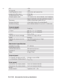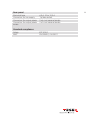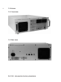
1
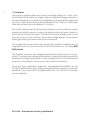
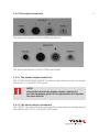
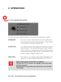
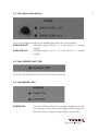
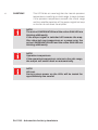
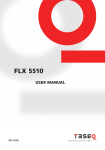
® E stablished 1981 Advanced Test Equipment Rentals www.atecorp.com 800-404-ATEC (2832) 1 PA 5740 - Automotive bAttery simulAtors user mAnuAl 601-309A PA 5740 - Automotive battery simulators User Manual PA 5740 - Automotive battery simulators Contents 1 The PA 5740 Automotive battery simulator 1.1Introduction 1.2Features 2 Safety instructions 2.1 Danger classification 2.2 Pictograms on Test System 2.3 Excess voltage category 2.4 Application area 2.5 Safety of operation 2.6 Operating personnel 2.7 Persons responsible for safety measures 2.8 Accident prevention regulations 2.9 Infringement of safety regulations 2.10 Proper use 3Installation/Set-Up 3.1 Checking the shipment 3.2 Delivery contents 3.2.1 Standard accessories 3.2.2 Documentation 3.3 Set-Up 3.3.1 Operating position 3.3.2 Line voltage connection and grounding 3.4 PA 5740 Front panel connectors 3.4.1 The control connector 3.4.2 The output connectors 4Operation 4.1 The compensation button 4.2 The gain button 5 5 6 7 7 8 9 9 9 10 10 10 10 10 11 11 11 11 11 11 12 12 13 13 15 16 16 17 4 4.3 The current limit LED 4.4 The errors LEDs 5Applications 5.1 Compliant with ISO 7637 (and similar) for transient immunity 5.2 Voltage variations for starting profiles 5.3 Fast rise time for challenging voltage dip applications 5.4 Voltage ripple and sine wave noise simulations 5.5 Example application with NSG 5500 and NSG 5600 6Maintenance 6.1 Cleaning the equipment 6.2 Moving and storing the amplifier 6.3 Protection 6.3.1 Fuses Specifications 7 7.1 Environmental conditions 7.3 Pictures 7.3.1 Front view 7.3.2 Rear view 8 Declaration of conformity (CE) 9Addresses 17 17 19 19 19 20 20 21 22 22 22 23 23 27 27 30 30 30 31 32 1 tHe PA 5740 Automotive bAttery simulAtor 1.1 Introduction The PA 5740 range of battery simulators is high performance power amplifier providing a stable and rugged power source for laboratory applications. The amplifier has been designed specifically to simulate battery supplies. Such as 12, 24 and 42 V vehicle electrical systems. It may be used on its own or integrated with the Teseq Automotive EMC Test System consisting of NSG 5000, NSG 5200, NSG 5500, NSG 5600 (hereafter referred to as NSG 5000 series) and AutoStar software. Designed to meet EMC (electromagnetic compatibility) immunity testing requirements for the automotive industry. Applicable standards include: ISO 7637, ISO 16750, JASO D001, MIL-STD-461E, SAE J1113 as well as automobile manufacturer specifications. Types of testing include supply voltage variations, dips and drops, ISO pulses 2b and 4, load dump pulse, starting profiles, power cycling, battery recovery, reset behaviour, fuel pump transient, conducted sine waves, ground shift, jump start and over voltage, as well as providing a programmable DUT (device under test) power source during all phases of testing. 5 6 1.2 Features The output is programmable over a minimum voltage range from - 60 to + 60 V which allows the simulation of a large range of pulses and voltage variations. A remote sensing input is provided to compensate for output cable voltage drop (up to 4 V). The output provides a wide bandwidth (DC to >150 kHz), a fast output slew rate and low source impedance (<10 mOhm). All controls, displays and connections are located on the front panel for ease of access and visibility except the output connectors which are even located on both the front and the back panel. These facilities include: voltage input; current limit input, current limit indicator, current and voltage display, compensation mode, gain setting and output and sense connectors. The voltage and current control and monitoring interface is realized with an integrated control D-type connector for direct connection to the Teseq NSG 5000 series. The amplifier inputs are over voltage protected and outputs short circuit protected. The mains input voltage is selectable by Teseq factory/service points to accept world voltage supplies and is under voltage protected. Overtemperature protection is monitored on the internal heat sink and transformer. There are three selectable ranges for compensation/bandwidth for the PA 5740. Bandwidths are high, allowing fast slew rates as required by numerous standards. The current limit is programmable from 10 to 100% of the output current capability. PA 5740 - Automotive battery simulators 2 sAFety instuCtions Be sure to observe the following safety precautions before you install the test system and put it into operation! Also follow all safety instructions in the manuals of the connected peripheral devices. NOTE! Always keep operating instructions for future use! Store the operating instructions so that they are always accessible to all operating personnel. Every operator must be informed exactly where the operating instructions have been stored. 2.1Dangerclassification The safety precautions in the manual are always presented in the same format. They consist of the signal word, which contains information on the type and source of the danger, an explanation of the preventative measures to be taken and a standard warning symbol. The following table gives you an overview of the signal words used, their allocation to specific dangers and their possible consequences. 7 8 Warning symbol Signal word Definition DANGER! There exists a high risk of fatality or severe injury if the necessary preventative measures are not taken. WARNING! Potentially dangerous situation that can result in injuries and serious damage to equipment if the necessary preventative measures are not taken. CAUTION! Situations that could arise when objects or equipment are damaged if no measures are taken to prevent this. NOTE! Information on important special features. TIP! User tips and information. 2.2 Pictograms on Test System Various warning symbols are applied to the test system. The following table provides you with an overview of the assignment of symbols (pictograms) and signal words to the specific danger. Pictogramm Definition Possibly dangerous situation that can result in injuries and serious damage to the equipment. Situation that can result in damage to the equipment. PA 5740 - Automotive battery simulators 2.3 Excess voltage category The test equipment PA 5740, as described in this manual, is related to the excess voltage category II according IEC 60664. 2.4 Application area These instructions apply to the entire system. Other safety regulations for components used or devices additionally installed in the test system are not voided by these instructions and are to be followed. 2.5 Safety of operation Reliable function and safe operation of the test equipment are ensured only if the relevant general precautions as well as all safety instructions given in this manual are observed. In particular, observe the following: Connect the device only to line voltage that confirms to the power specification given on the type label (on the back of the test equipment). Do not touch any conductive parts at the output connectors, the fixture and the test object during a test run. Disconnect the device from the mains before opening the casing for maintenance or repair. During the operation of the test equipment always observe the relevant rules of ESD (Electro Static Discharge) protection. To guarantee the EMC features of the device, the control computer must meet the requirements of the EN 50082, EN 55011, EN 61000 standard. Make sure the environmental conditions described in chapter 7.1 Environmental conditions exist. 9 10 2.6 Operating personnel The test system should only be operated by qualified personnel. Making settings, maintenance work and repairs on an opened device can only be carried out by the appropriately trained personnel. Teseq and its representatives will only guarantee for maintenance and repair when it has been carried out by its own service personnel. 2.7 Persons responsible for safety measures Those considered responsible for safety are the owner, the user and the operator. In addition, you are responsible for all safety measures that are indirectly linked to the test system. More relevant information can be found in the accident prevention regulations. Also observe all the safety measures for additional devices used together with the test system. 2.8 Accident prevention regulations When dealing with the test system observe the industrial health and safety standards pertaining to electrical test installations in your country. 2.9 Infringement of safety regulations If the system is not functioning as described or is visibly damaged, this can affect its safety status. If this is the case the system must be shut down immediately, and in such a way that it cannot be started up again accidentally by any third persons. Please inform the Service Department at Teseq or its representative. 2.10 Proper use The test system is exclusively for the testing of electrical devices and components in accordance with the test system specifications. PA 5740 - Automotive battery simulators 3 instAllAtion/set-uP 3.1 Checking the shipment Upon receiving the shipment, first check the packaging and outer equipment for visible damage. Also, check packaging and casings of peripherals (if any). Record in writing any defects which were possibly caused in transit. If the shipment shows damage or is not complete, immediately advise the shipping agency and/or your dealer. 3.2 Delivery contents The standard delivery contains the basic unit as well as several attachments and accessories. 3.2.1 Standard accessories One power cable 3.2.2 Documentation The following manuals are supplied: This PA 5740 Automotive battery simulators hardware guide 3.3 Set-up CAUTION! Risk of damage by condensation! When the equipment is brought from cold to warm environment, a dangerous conditions can result from condensation. Do not operate the system until all parts of the system have reached room temperature. 11 12 The equipment may be set-up by qualified personnel only. It is imperative to observe the safety instructions at the beginning of this manual. The equipment will be safe to operate and perform to its specifications only under the environmental conditions found in chapter 7.1 Environmental conditions. 3.3.1 Operating postition The tester must be placed in upright position firmly and securely during operation. There must be enough space around the equipment to ensure a sufficient air flow for cooling. The ventilation grilles must be kept free. 3.3.2 Line voltage connection and grounding CAUTION! Risk of destruction by wrong main voltage! If the voltage specified on the type label (on the back of the equipment) does not agree with the voltage in your local mains supply, the tester can be destroyed. Make sure the voltage specified on the type label of the power supply agrees with your local mains voltage. Do not use power supplies that deliver output voltage other than 100 V/12,5 A, 120 V/10 A or 230 V/6,3 A. The power cord of the equipment is located on the back of the equipment. The power input is secured with a delayed action fuse (for details, refer to chapter 5.3 Protection). The power plug and outlet must have grounding contacts. PA 5740 - Automotive battery simulators DANGER! Danger to life by interruption of the grounding! If the grounding is interrupted inside or outside the equipment, the PA 5740 will become a source of danger. Follow the regulations for the grounding of the system. 3.4 PA 5740 Front panel connectors 3.4.1 The control connector The “CONTROL” connector is an input port for the function generator; it can be directly connected to the appropriate connector at the function generator card of your NSG series. To benefit from all advantages of the PA 5740 it is best controlled by your NSG 5000 series. But of course if the specifications described in chapter 3.4.1.2 CONTROL input specifications are considered, the PA 5740 can be controlled by any other analog function generator as well. 13 14 3.4.1.1 Pin count of the control I/O DSub connector 3.4.1.2 CONTROL input specifications The Vprog+ pin of the connector is the voltage Input of the battery simulator. The output of the battery simulator can be described as U OUTPUT = Vprog+ x GAIN. The GAIN can either be set to 7 or 1. Ilim+ is the analog control of the current limit. The input is 1-10 V which equals a current limit of 1-10 A. CAUTION! Risk of destruction by wrong voltage! If the PA 5740 is controlled by any alternative function generator it care has to be taken that the voltage at the Ilim+ pin must be at least +1 V. Make sure the voltage at the Ilim+ pin is at least +1 V. PA 5740 - Automotive battery simulators 3.4.2 The output connectors The output connectors of the PA 5740 series (front) The output connectors of the PA 5740 series (back) 3.4.2.1 The power output connectors The “POSITIVE/NEGATIVE POWER” connectors are used to connect the output to the DUT or to the NSG 5000 series. NOTE! Information about the power output connectors: See the hardware guide of the appropriate test system for more details. 3.4.2.2 The sense output connectors The “SENSE” connectors may be connected to compensate for voltage drop of the cables to the DUT or to the NSG 5000 series. 15 16 4operation 4.1 The compensation button Pressing this button toggles between the available compensation modes: STANDARD This is the normal operating mode with a good compromise between stability and bandwidth. The bandwidth in this selection is approximately 40 kHz CAPACITIVE This mode is specifically designed for capacitive and/or reactive loads. This reduced bandwidth, high stability mode is perfect for using during normal transient testing, conducted sine wave (CSW) testing. The bandwidth in this mode is limited to approximately 3 kHz. HIGH FREQ This mode is for testing where high bandwidths are required. This mode allows frequencies up to 150 kHz. Risk of destruction of the DUT or couplers! Monitor the DUT to ensure no ringing or excessive overshoot is present. In case there is a question you should use the CAPACITIVE mode. PA 5740 - Automotive battery simulators 4.2 The system stop button This button toggles between the available gain options of the amplifier: GAIN HIGH (x7) Indicates a gain of seven. 1 V in will result in 7 V output voltage. GAIN LOW (x1) Indicates a gain of one. 1 V in will result in 1 V output voltage. 4.3 The CURRENT LIMIT LED This LED indicates that the current limit has been reached. 4.4 The ERRORS LEDs POWER FAIL This LED indicates if any of the system voltage check fails. It is blinking in case the power stage power supply unit fails and it stays constant if the auxiliary supply fails. 17 18 OVERTEMP This LED blinks as a warning that the internal operation temperature is reaching a critical range. It stays constant if the operation temperature exceeds the critical range and the amplifier switches off the output signal but keep on the fan to cool down the amplifier. NOTE! The active COMPENSATION and the active GAIN LED are blinking additionally. If the output signal is switched off because the amplifier detected over temperature or a power error the active COMPENSATION LED and the active GAIN LED are blinking additionally. NOTE! Operation temperature. If the operation temperature returns to the safe range, the output will switch back on automatically. NOTE! LED test. During system power up the LEDs will be tested for approximately one second. PA 5740 - Automotive battery simulators 5Applications 5.1 Compliant with ISO 7637 (and similar) for transient immunity The PA 5740 is designed to act as the battery source for transient immunity tests. Most transients must be coupled onto battery voltage and the NSG 5000 series with its internal coupling couples the transient and the DC voltage as required by the standards. Designed with low internal resistance and low noise, the PA 5740 is compliant with section 5.4 of ISO 7637-2:2004. For this application please use compensation mode CAPACITIVE. UA 0 5.2 Voltage variations for starting profiles The PA 5740 series is often used for starting profile simulation (pulse 4 and variants). In addition, several standards require synchronized starting profiles. Utilizing the NSG 5000 series for control, the PA 5740 (or the PA 5840) is the best solution for all known starting profiles with up to four synchronized starting profiles. The PA 5840 is another automotive battery simulator from Teseq but for greater power. See the specifications of the NSG 5000 series for details. For this application please use compensation mode CAPACITIVE. 19 20 UA 0V 5.3 Fast rise time for challenging voltage dip applications Certain standards, such as Ford ES-XW7T-1A278-AC specify ~10 μs rise and fall times for the battery simulator. The PA 5740 is designed to fully meet the relevant standards and is often used for dips and drops applications where <10 μs rise times are specified. For this application please use compensation mode STANDARD. 5.4 Voltage ripple and sine wave noise simulations The PA 5740 is also commonly used to simulate sine wave noise on battery voltage. A user could, for example, simulate a 1 V p/p sine wave onto a 42 V network using high battery current. This is a common requirement of manufacturers’ standards. For this application please use suitable compensation mode (as frequency required). PA 5740 - Automotive battery simulators 2 Aux Bat PA 5840 PA 5840 Coil PC Master EUT output PM output IEEE Auxiliary input 2 2 Sense outputs 2 SVI output Sense outputs Battery input 2 EUT output 2 2 CT 5610 FG 5620 Blank Slot TC 5650 PA 5640 DS 5630 NSG 5600 IEEE LD 5055 Power entry / FT 5530 Battery switch Controller MT 5510 NSG 5500 HVPSU DUT 5.5 Example application with NSG 5500 and NSG 5600 21 22 6Maintenance Under normal conditions, it does not take much effort to keep your test equipment in good working order. CAUTION! Protect the equipment against moisture, heat and dust. 6.1 Cleaning the equipment To clean the equipment, use a dry, clean cloth. Never use water, any other liquid or detergent. 6.2 Moving and storing the amplifier The amplifier must be installed/uninstalled only by qualified personnel. Before moving the equipment (even over a short distance), you must first turn it off and disconnect it from the mains. Remove any fixturing devices and/or test objects. Also, disconnect the amplifier from any peripherals. For longer transit, protect the equipment against humidity, dust and shock by proper packaging. The equipment must be stored in upright (working) position. Make sure the equipment is protected against humidity, dust and dirt. Observe the environmental conditions specified in chapter 7.1 Environmental conditions. PA 5740 - Automotive battery simulators 6.3 Protection The PA 5740 Automotive battery simulators are protected with a slow-blow fuse. Dependent on the supply voltage a fuse with a different ampere rating is equipped: Type No of phases Supply voltage Ueff Primary current Ieff PA 5740-75 / 100 V 1 100 V 12.5 A PA 5740-75 / 120 V 1 120 V 10 A PA 5740-75 / 230 V 1 230 V 6.3 A 6.3.1 Fuses The fuses are placed in the mains voltage selector. To exchange a fuse, proceed as follows: DANGER! Dangerous voltages and currents are present in the PA 5740! Disconnect the amplifier from the mains by disconnecting the power cord before working on the mains voltage selector! 23 24 Carefully loosen the drawer from the input connector assembly using a screwdriver and turning it slightly in both directions as shown in the pictures below. Pull out the drawer from the input connector assembly. PA 5740 - Automotive battery simulators Remove the defect fuse. Remove the defect fuse. CAUTION! Risk of destruction by wrong fuses! Use the following fuse types 5 x 20 mm, 6 A, time-lag 25 26 Push the drawer back in until it is fixed to the input connector assembly again. Now reconnect the PA 5740 to the mains. PA 5740 - Automotive battery simulators 7SPECIFICATIONS 7.1 Environmental conditions Temperature range: Humidity: Air pressure: Protection class: Operation at +10 to +40°C storage at -10 to +60°C 30 to 75% (non condensing) 860 to 1060 hPa IP20 7.2 Technical capabilities General Forward voltage gain (switchable) Bandwidth (-3 dB) Overtemperature shutdown Supply Supply voltage Supply frequency Supply power Output Output voltage range Max continuous output Current Output impedance Output accuracy PA 5740 7/1 DC to 40 kHz (standard) to 150 kHz (high freq) Thermal sensors trip at 80°C (warning) and 90°C (output shut off) 1 ph 100/120/230 V ± 10% L, N, PE 47 to 63 Hz 1.4 kVA -60 to +60 V ±10 A <10 mOhm Typical <1% 27 28 DC AC signals Load regulation, Uout Long term drift, Uout Temperature drift, Uout Output ripple, Uout Recovery Output rise time Remote sensing < 2% < 2% 0.2% max. with sense line 0.1% max 0.02%/°C <10 mVrms for more details, and measurements methods, see the calibration report >90% of excursion within 25 μs <3 μs (high freq)/<10 μs (standard) Auto compensation for up to 4 V cable loss Control signals Input impedance U Input I Input Display for output voltage (RMS) Display for output current (RMS) 10 kOhm gain x1: 1 V = 1 V (output) gain x7: 1 V = 7 V (output) 10 V = 10 A 0 to 60 V ±1 digit ±2% of Reading 0 to 10 A continuous ±1 digit ±2% of reading Mechanical specification Standard housing Style/construction Overall dimensions H x W x D Mass 19” cabinet 188 x 484 x 560 mm 7.4 x 19 x 22.2“ 35 kg/77 lbs Control panel 2 x Display 3½ digit red LED Voltage, current RMS 1 x Connector 9-pole male D Uprog; Iprog Front panel Connector for output power 2 x 4 mm banana female Connector for output power 2 x 2 mm banana female sense Power switch 2 position OFF - ON PA 5740 - Automotive battery simulators Rear panel Electrical fuse Connector for line supply Connector for output power Connector for output power sense Standard compliance Safety EMC 29 6,3 A, 10 or 12,5 A 1-phase socket 2 x 4 mm banana female 2 x 2 mm banana female IEC 1010-1 EN 50082-1, EN 55011 30 7.3 Pictures 7.3.1 Front view 7.3.2 Rear view PA 5740 - Automotive battery simulators 8 Declaration of conformity (CE) 31 32 Headquarters Teseq AG 4542 Luterbach, Switzerland T + 41 32 681 40 40 F + 41 32 681 40 48 sales @ teseq.com www.teseq.com Manufacturer Teseq AG 4542 Luterbach, Switzerland T + 41 32 681 40 40 F + 41 32 681 40 48 sales @ teseq.com China Teseq Company Limited T + 86 10 8460 8080 F + 86 10 8460 8078 chinasales @ teseq.com France Teseq Sarl T + 33 1 39 47 42 21 F + 33 1 39 47 40 92 francesales @ teseq.com Germany Teseq GmbH T + 49 30 5659 8835 F + 49 30 5659 8834 desales @ teseq.com Japan Teseq K.K. T + 81 3 5725 9460 F + 81 3 5725 9461 japansales @t eseq.com Singapore Teseq Pte Ltd. T + 65 6846 2488 F + 65 6841 4282 singaporesales @ teseq.com Switzerland Teseq AG T + 41 32 681 40 50 F + 41 32 681 40 48 sales @ teseq.com Taiwan Teseq Ltd. T + 886 2 2917 8080 F + 886 2 2917 2626 taiwansales @ teseq.com UK Teseq Ltd. T + 44 845 074 0660 F + 44 845 074 0656 uksales @ teseq.com USA Teseq Inc. T + 1 732 417 0501 F + 1 732 417 0511 Toll free +1 888 417 0501 usasales @ teseq.com © December 2010 Teseq® Specifications subject to change without notice. Teseq® is an ISOregistered company. Its products are designed and manufactured under the strict quality and environmental requirements of the ISO 9001. This To find your local partner within document has been carefully checked. Teseq®’s global network, please go to However, Teseq® does not assume www.teseq.com any liability for errors or inaccuracies.