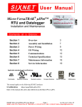
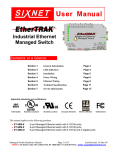
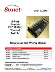
1
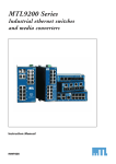
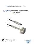
AutomationDirect.com E-SW05U Industrial Ethernet Real-time Switch Contents at a Glance: Section 1 General Information Page 5 Section 2 LED Indicators Page 6 Section 3 Installation Page 7 Section 4 Power Wiring Page 8 Section 5 Ethernet Wiring Page 9 Section 6 Switching Features Page 11 Section 7 Technical Specifications Page 13 This manual applies to the Industrial Ethernet 5 port Switch (E-SW05U) E-SW05U User Manual Rev. 1 Page 1 WARNING Thank you for purchasing automation equipment from Automationdirect.com. We want your new automation equipment to operate safely. Anyone who installs or uses this equipment should read this publication (and any other relevant publications) before installing or operating the equipment. To minimize the risk of potential safety problems, you should follow all applicable local and national codes that regulate the installation and operation of your equipment. These codes vary from area to area and usually change with time. It is your responsibility to determine which codes should be followed, and to verify that the equipment, installation, and operation are in compliance with the latest revision of these codes. At a minimum, you should follow all applicable sections of the National Fire Code, National Electrical Code, and the codes of the National Electrical Manufacturer’s Association (NEMA). There may be local regulatory or government offices that can also help determine which codes and standards are necessary for safe installation and operation. Equipment damage or serious injury to personnel can result from the failure to follow all applicable codes and standards. We do not guarantee the products described in this publication are suitable for your particular application, nor do we assume any responsibility for your product design, installation, or operation. Our products are not fault-tolerant and are not designed, manufactured or intended for use or resale as on-line control equipment in hazardous environments requiring fail-safe performance, such as in the operation of nuclear facilities, aircraft navigation or communication systems, air traffic control, direct life support machines, or weapons systems, in which the failure of the product could lead directly to death, personal injury, or severe physical or environmental damage (“High Risk Activities”). Automationdirect.com specifically disclaims any expressed or implied warranty of fitness for High Risk Activities. For additional warranty and safety information, see the Terms and Conditions section of our Desk Reference. If you have any questions concerning the installation or operation of this equipment, or if you need additional information, please call us at 770-844-4200. This publication is based on information that was available at the time it was printed. At Automationdirect.com we constantly strive to improve our products and services, so we reserve the right to make changes to the products and/or publications at any time without notice and without any obligation. This publication may also discuss features that may not be available in certain revisions of the product. TRADEMARKS This publication may contain references to products produced and/or offered by other companies. The product and company names may be trademarked and are the sole property of their respective owners. Automationdirect.com disclaims any proprietary interest in the marks and names of others. Copyright 2001, Automationdirect.com Incorporated All Rights Reserved No part of this manual shall be copied, reproduced, or transmitted in any way without the prior, written consent of Automationdirect.com Incorporated. Automationdirect.com retains the exclusive rights to all information included in this document. E-SW05U User Manual Page 2 of 13 AVERTISSEMENT Nous vous remercions d'avoir acheté l'équipement d'automatisation de Automationdirect.comMC. Nous tenons à ce que votre nouvel équipement d'automatisation fonctionne en toute sécurité. Toute personne qui installe ou utilise cet équipement doit lire la présente publication (et toutes les autres publications pertinentes) avant de l'installer ou de l'utiliser. Afin de réduire au minimum le risque d'éventuels problèmes de sécurité, vous devez respecter tous les codes locaux et nationaux applicables régissant l'installation et le fonctionnement de votre équipement. Ces codes diffèrent d'une région à l'autre et, habituellement, évoluent au fil du temps. Il vous incombe de déterminer les codes à respecter et de vous assurer que l'équipement, l'installation et le fonctionnement sont conformes aux exigences de la version la plus récente de ces codes. Vous devez, à tout le moins, respecter toutes les sections applicables du Code national de prévention des incendies, du Code national de l'électricité et des codes de la National Electrical Manufacturer’s Association (NEMA). Des organismes de réglementation ou des services gouvernementaux locaux peuvent également vous aider à déterminer les codes ainsi que les normes à respecter pour assurer une installation et un fonctionnement sûrs. L'omission de respecter la totalité des codes et des normes applicables peut entraîner des dommages à l'équipement ou causer de graves blessures au personnel. Nous ne garantissons pas que les produits décrits dans cette publication conviennent à votre application particulière et nous n'assumons aucune responsabilité à l'égard de la conception, de l'installation ou du fonctionnement de votre produit. Nos produits ne sont pas insensibles aux défaillances et ne sont ni conçus ni fabriqués pour l'utilisation ou la revente en tant qu'équipement de commande en ligne dans des environnements dangereux nécessitant une sécurité absolue, par exemple, l'exploitation d'installations nucléaires, les systèmes de navigation aérienne ou de communication, le contrôle de la circulation aérienne, les équipements de survie ou les systèmes d'armes, pour lesquels la défaillance du produit peut provoquer la mort, des blessures corporelles ou de graves dommages matériels ou environnementaux («activités à risque élevé»). La société Automationdirect.comMC nie toute garantie expresse ou implicite d'aptitude à l'emploi en ce qui a trait aux activités à risque élevé. Pour des renseignements additionnels touchant la garantie et la sécurité, veuillez consulter la section Modalités et conditions de notre documentation. Si vous avez des questions au sujet de l'installation ou du fonctionnement de cet équipement, ou encore si vous avez besoin de renseignements supplémentaires, n'hésitez pas à nous téléphoner au 770-844-4200. Cette publication s'appuie sur l'information qui était disponible au moment de l'impression. À la société Automationdirect.comMC, nous nous efforçons constamment d'améliorer nos produits et services. C'est pourquoi nous nous réservons le droit d'apporter des modifications aux produits ou aux publications en tout temps, sans préavis ni quelque obligation que ce soit. La présente publication peut aussi porter sur des caractéristiques susceptibles de ne pas être offertes dans certaines versions révisées du produit. MARQUES DE COMMERCE La présente publication peut contenir des références à des produits fabriqués ou offerts par d'autres entreprises. Les désignations des produits et des entreprises peuvent être des marques de commerce et appartiennent exclusivement à leurs propriétaires respectifs. Automationdirect.comMC nie tout intérêt dans les autres marques et désignations. Copyright 2001, Automationdirect.comMC Incorporated Tous droits réservés Nulle partie de ce manuel ne doit être copiée, reproduite ou transmise de quelque façon que ce soit sans le consentement préalable écrit de la société Automationdirect.comMC Incorporated. Automationdirect.com MC conserve les droits exclusifs à l'égard de tous les renseignements contenus dans le présent document. E-SW05U User Manual Page 3 of 13 INSTALLATION AND HAZARDOUS AREA WARNINGS: This switch should not be used to replace proper safety interlocking. No software-based device (or any other solid-state device) should ever be designed to be responsible for the maintenance of consequential equipment or personnel safety. In particular, no responsibility for damages, either direct or consequential, that result from the use of this equipment in any application will be taken by the distributor of this product. All power, input and output (I/O) wiring must be in accordance with Class I, Division 2 wiring methods and in accordance with the authority having jurisdiction. WARNING (EXPLOSION HAZARD) - SUBSTITUTION OF COMPONENTS MAY IMPAIR SUITABILITY FOR CLASS 1, DIVISION 2. WARNING (EXPLOSION HAZARD) - WHEN IN HAZARDOUS LOCATIONS, DISCONNECT POWER BEFORE REPLACING OR WIRING UNITS. WARNING (EXPLOSION HAZARD) - DO NOT DISCONNECT EQUIPMENT UNLESS POWER HAS BEEN SWITCHED OFF OR THE AREA IS KNOWN TO BE NONHAZARDOUS. FCC Statement: This equipment has been tested and found to comply with the limits for a Class B digital device, pursuant to Part 15 of the FCC Rules. These limits are designed to provide reasonable protection against harmful interference in a residential installation*. This equipment generates, uses and can radiate radio frequency energy and, if not installed and used in accordance with the instructions, may cause harmful interference to radio communications. However, there is no guarantee that interference will not occur in a particular installation. If this equipment does cause harmful interference to radio or television reception, which can be determined by turning the equipment off and on, the user is encouraged to try to correct the interference by one or more of the following measures: Reorient or relocate the receiving antenna; Increase the separation between the equipment and receiver; Connect the equipment into an outlet on a circuit different from that to which the receiver is connected; Consult the dealer or an experienced radio/TV technician for help. * E-SW05U is not intended for residential use. Copyright & Trademarks: Copyright 2001, All Rights Reserved. Note: All information in this document is subject to change without notice. E-SW05U User Manual Page 4 of 13 Section 1 General Information Overview This manual will help you install and maintain the Industrial Ethernet Switch. This unmanaged switch is extremely easy to install and operate because little or no user configuration is required. Once the Ethernet connections are made and the unit is powered up it will immediately begin to operate. Operation Unlike an Ethernet hub that broadcasts all messages out all ports, the Industrial Ethernet Switch will intelligently route Ethernet messages only out the appropriate port. The major benefits of this are increased bandwidth and speed, reduction or elimination of message collisions, and deterministic performance when tied with real-time systems. The Industrial Ethernet Switch supports both 10BaseT (10 Mbps) and 100BaseTx (100 Mbps) on its RJ45 ports. Each of these ports will independently auto-sense the speed, allowing you to interface to regular or fast Ethernet devices. Refer to Section 6 for more information on Industrial Ethernet Switch operation and features. Performance Specifications These general specifications apply to the Industrial Ethernet Switch. Refer to Section 7 for complete technical specifications. Ports Required Voltage Ethernet Standards Ethernet Protocols Speed Per Port Ethernet Isolation Operating Temp. Humidity Screw Terminals Standards and Safety 10/100BaseT(x) (Shielded RJ45) 10 - 30 VDC (see Section 7 for current draw) IEEE 802.3 (10BaseT), 802.3u (100BaseTX), 802.3x (Full Duplex) All standard IEEE 802.3 protocols supported RJ45: 10 or 100 Mbps (half duplex), 20 or 200 Mbps (full duplex) 1200 Volts RMS (for 1 minute) -40 to 85 °C 5 to 95% (non-condensing) 5 port switch: 14 AWG max. (tighten to 3.48 in-lbs. max.) The Industrial Ethernet Switch meets the following standards: Electrical safety - UL 508, CSA C22/14; EN61010-1 (IEC1010) EMI emissions - FCC part 15, ICES 003, EN55022; Class B EMC immunity – EN61326-1(EN61000-4--2, 3, 4, and 6) Hazardous locations – UL 1604, CSA C22.2/213 (Class 1, Div. 2), Groups A, B, C, D; Cenelec EN50021 (Zone 2) Install the Industrial Ethernet Switch in accordance with local and national electrical codes. Lightning Danger: Do not work on equipment during periods of lightning activity. Do not connect a telephone line into one of the Ethernet RJ45 connectors. E-SW05U User Manual Page 5 of 13 Section 2 Overview LED Indicators The Industrial Ethernet Switch has communication LEDs for each port and a power LED. FIVE PORT SWITCH Power LED This LED will be on solid when proper power has been applied to the unit. ACT / LNK LEDs The activity (ACT) and link (LNK) indication is combined into one LED on the Industrial Ethernet Switch. There is one of these LEDs per port. OFF – This would indicate that there is not a proper Ethernet connection (Link) between the port and another Ethernet device. Make sure the proper cable type is in use and that it has been plugged securely into the ports at both ends. See section 5 for proper Ethernet cabling. ON Solid (not flashing) – This would indicate that there is a proper Ethernet connection (Link) between the port and another Ethernet device, but no communications activity is detected. Flashing - This would indicate that there is a proper Ethernet connection (Link) between the port and another Ethernet device, and that there is communications activity. 10 / 100 LEDs This LED indicates what speed of communications is detected on the port. There is one of these LEDs per RJ45 port OFF – A 10 Mbps (10BaseT) connection is detected. ON – A 100 Mbps (100BaseTx) connection is detected. (Mbps = Megabits per Second) E-SW05U User Manual Page 6 of 13 Section 3 Overview Installation The Industrial Ethernet Switch can be snapped onto a standard DIN rail (EN50022) or screwed directly to a flat panel. Refer to the mechanical drawings below. 0.28" [0.71cm) 2.92" [7.42cm] Automation Direct E-SW05U 0.25" [0.64cm] 3.17" [8.05cm] Max. Height of Panel: E-SW05U: 1.75" (4.45 cm) ? 0.17" [? 0.43] (clear for #8 screw) 1.10" [2.79cm] 3.17" [8.05cm] DIN EN 50022 4.47"[11.35cm] 1.67" [4.24cm] 4.75"[12.07cm] E-SW05U E-SW05U User Manual Page 7 of 13 Section 4 Overview Power Wiring The Industrial Ethernet Switch can be powered from the same DC source that is used to power your I/O devices. 10 to 30 VDC needs to be applied to terminals 2 and 3. Refer to the wiring diagram below. ACT/ LNK 10/ 100 ACT/ LNK 10/ 100 ACT/ LNK 10/ 100 ACT/ LNK 10/ 100 ACT/ LNK 10/ 100 PWR Uplink Port 1 2 3 PWR PWR + - +Screw Torque The screw terminals should be tightened to a maximum 3.48 in-lbs (0.4 Nm). E-SW05U User Manual Page 8 of 13 Section 5 Overview Ethernet Wiring The Industrial Ethernet Switch provides connections to Ethernet devices on the factory floor. Typically the uplink port is used to connect to another Ethernet switch or hub that is connected to the main Ethernet backbone. The other four Ethernet ports are then connected to Ethernet devices such as PLCs, Ethernet I/O, or industrial computers. Electrical isolation is provided on the Ethernet ports for increased reliability. Please follow normal 10/100BaseT(x) wiring practices when installing the Industrial Ethernet Switch. Typical Industrial Ethernet Switch Installation Ethernet RJ45 Wiring Guidelines Ethernet RJ45 Cable Type Use data-quality (not voice-quality) twisted pair cable rated category 5 with standard RJ45 connectors. For best performance use shielded cable. Please note that these cables are available as straight-thru or cross-over configurations. The following is a guide for when to use each type: Ethernet Switch Cable Type Ethernet Switch Cable Type STANDARD Port to to Use UPLINK Port to to Use PC card Straight-thru PC card Cross-over Ethernet I/O Straight-thru Ethernet I/O Cross-over PLC Straight-thru PLC Cross-over Other Ethernet enabled Straight-thru Other Ethernet enabled Cross-over devices devices * Straight-thru Standard port on Straight* Uplink port on another (see note) another switch or hub thru switch or hub * Note: Some Ethernet switches and hubs have a settable switch on their Uplink port that will change how the port is internally wired. Make sure this switch is set in the “To Hub/Switch (MDI)” position as opposed to the “To PC (MDI-X)” position. Straight-thru Cable Wiring Pin 1 Pin 1 Pin 2 Pin 2 Pin 3 Pin 3 Pin 6 Pin 6 E-SW05U User Manual Cross-over Cable Wiring Pin 1 Pin 3 Pin 2 Pin 6 Pin 3 Pin 1 Pin 6 Pin 2 Page 9 of 13 Ethernet Connector Pin Positions Pin # 1 2 3 6 Assignment TX+ TXRX+ RX- Ethernet Connector Pin Assignments Cable Distance The maximum cable length for 10/100BaseT(x) is typically 100 meters (328 ft.). Refer to the following chart for some general guidelines. From To Maximum Distance 100 meters (328 feet) Switch Switch or Hub PLC, Ethernet I/O, PC, etc. 100 meters (328 feet) Switch or Hub Note: Hubs and Switches are different devices. Hubs simply broadcast all messages out all ports. Switches intelligently route messages only out the appropriate port. All the devices described in this manual are Switches. Full or Half Duplex Operation The RJ45 ports will auto-sense for Full or Half duplex operation. No user configuration is necessary. E-SW05U User Manual Page 10 of 13 Section 6 Switching Features Switching Features Here’s a brief explanation of the features found in the Industrial Ethernet Switch documented by this manual. 10BaseT and 100BaseTx Autodetection Standard Ethernet (10BaseT) has a maximum speed of 10 Mbps (megabits per second). Fast Ethernet (100BaseTx) has a maximum speed of 100 Mbps. The RJ45 ports on the Industrial Ethernet Switch automatically supports both types. 1.4 Gbps combined bandwidth With full duplex and 100BaseTX communications, each port can provide a full 200 Mbps of data throughput. 1K MAC addresses with automatic learning, aging and migration Each Ethernet device inserts its unique “MAC” address into each message it sends out. The port on the switch used for a given MAC address is automatically learned when a frame is received from that address. Once an address is learned, the switch will route messages to only the appropriate port, instead of broadcasting messages out all ports like a hub. A time stamp is also placed in memory when a new address is learned. This time stamp is used with the aging feature, which will remove unused MAC addresses from the table after 300 seconds. If a device moves, the associated port on the switch will be changed (migrated) as needed. Up to 1,024 MAC addresses can be stored and monitored at any time. Auto-sensing speed and flow control The RJ45 ports of the Industrial Ethernet Switch will auto-negotiate with the connected device to determine the optimal speed (10 Mbps vs. 100 Mbps) and flow control for each port. Automatic power saving If there is no cable on a port, most of the circuitry for that port is disabled to save power. Backoff operation The Industrial Ethernet Switch will drop a packet after 16 collisions. Back pressure for half-duplex The Industrial Ethernet Switch will apply “back pressure” when necessary with half-duplex operation. This “back pressure” will reduce congestion on busy networks. Broadcast storm protection Broadcasts and multicasts are limited to 25% of the available bandwidth. Buffering SRAM is used for buffering the messages. There are 1024 (128 bytes each) buffers available. Each port is allocated 205 buffers. E-SW05U User Manual Page 11 of 13 Unmanaged operation The Industrial Ethernet Switch requires no supervisory processor to operate properly. Flow control The Industrial Ethernet Switch automatically supports flow control frames on both the transmit and receive sides. Forwarding The Industrial Ethernet Switch supports store and forward mode. It will forward messages with known addresses out only the appropriate port. Messages with unknown addresses, broadcast messages, and multicast messages will get forwarded out all ports except the source port. The Industrial Ethernet Switch will not forward error packets, 802.3x pause frames, or “local” packets. Full/Half duplex operation The RJ45 ports of the Industrial Ethernet Switch automatically support (auto-sense) both full and half duplex flow control. Illegal frames Illegal frames as defined by IEEE 802.3 will be dropped. This includes short frames, long frames, and FCS error frames. IEEE 802.3 compliant The Industrial Ethernet Switch strictly abides to the IEEE 802.3 standard for 10BaseT and 100BaseTX Ethernet communications. Late collision If a packet experiences collisions after 512 bit times of transmission, the packet will be dropped. Plug and play This means that most functions or features of the Industrial Ethernet Switch are automatic and that there are minimal or no optional parameters that need to be set. Just plug in your Ethernet cables, apply power, and the unit will immediately begin to operate. Protocol independent The Industrial Ethernet Switch will work with all popular Ethernet protocols and networks such as TCP/IP, the Internet (IP), UDP, NetBEUI, IPX, and many more. It is compatible with all protocols that run over standard Ethernet (IEEE 802.3). In fact, it will support packets of different protocols simultaneously. E-SW05U User Manual Page 12 of 13 Section 7 Technical Technical Specifications Here are the technical specifications for the Industrial Ethernet Switch covered by this manual. Specifications 10/100BaseT(x) Ports: 10/100BaseT(x) ports Protocols supported Ethernet compliancy Auto-sensing operation Auto-negotiating Flow control Ethernet isolation Plug and play Cable requirements Max. cable distance Shielded RJ45 All standard IEEE 802.3 IEEE 802.3 Full and half duplex 10BaseT and 100BaseTX Automatic 1200 VRMS 1 minute Yes Twisted pair (Cat. 5) (shielded recommended) 100 meters General: Forwarding mode Memory bandwidth MAC addresses Address learning Address aging Address migration Backoff operation Back pressure Buffering Illegal frames Late collisions Store and forward 1.4 Gbps 1K Automatic Remove old address after 300s Automatic Drops after 16 collisions Automatic for half-duplex 205 buffers per port (128 bytes per buffer) Dropped per 802.3 Dropped after 512 bit times Environmental: Required supply voltage Power consumption Power saving Max. screw terminal torque Max. wire gauge Operating temp. range Storage temp. range Humidity Flammability Electrical safety EMI emissions EMC immunity Surge withstand Vibration Hazardous locations Dimensions Mounting E-SW05U User Manual 10 – 30 VDC 1.9 W Automatic 5 port switch: 3.48 in-lbs (0.4 Nm). 12 AWG -40 to 85 C -40 to 85 C 5 to 95 % (non-condensing) UL 94V-0 materials UL508, CSA C22/14; EN61010-1 (IEC1010), CE FCC part 15, ICES 003, EN55022; Class B; CE EN61326-1 (EN61000-4-2, 3, 4, and 6), CE IEEE-472 (ANSI C37.90) IEC68-2-6 UL1604, CSA C22.2/213 (Class 1, Div. 2), Cenelec EN50021 (Zone 2) 3.25” x 4.75” DIN rail or panel direct Page 13 of 13