1
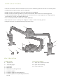
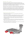
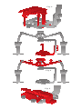
NBS-2X
N I M B U S
S TA B I L I Z E R
QUICK -S TART
GUIDE
PREC AUTIONS
•Please read and follow these instructions and keep this manual in a safe place.
•Keep this product away from children.
•Make sure everything is secure before proceeding.
•Make sure that this product is intact and that there are no missing parts.
•To avoid damage to this product, be careful not to overtighten or improperly
thread any of the threaded fittings.
•Do not exceed the maximum load capacity.
•Be careful not to catch your fingers in any of the moving parts.
•All photos are for illustrative purposes only.
1
2
4
3
2
6
7
5
8
9
10
OVERVIE W
STABILIZER:
ALSO INCLUDED:
1. Top knob
9.1/4″-20 camera screw
2. Thumb grips
10.3/8″-16 bushing
3.Handles
11.User manual
4.Bracket
5. Bracket locking knobs
6. Cheese plate
7. Cheese plate locking knobs
8. Cheese plate fore/aft adjustment
knob
3
B E F O R E Y O U S TA R T
This quick-start guide contains some basic instructions for
balancing the Nimbus Dual-Axis Mechanical Stabilizer. Setting up
a stabilizer like the Nimbus is not complicated, but it takes some
fine-tuning. Don’t feel discouraged if it takes a few tries to balance
the stabilizer—a little patience goes a long way.
Before you start, set up your camera in the exact way that you
are going to use it when shooting with the Nimbus Stabilizer. For
example, if you are going to use your camera’s LCD panel, make
sure to extend the panel before mounting your camera onto the
stabilizer. Similarly, make sure that any accessories are already
onboard. Any change to the camera’s balance will change its
center of gravity, making it necessary to readjust the stabilizer.
MOUNTING YOUR C AMER A
1. Remove the cheese plate by unscrewing the cheese plate
locking knobs. (Fig. 1)
2. Position your camera on the cheese plate, with your camera’s
lens at the front and the cheese plate’s hook at the rear, and
align your camera’s center of gravity on the cheese plate.
3. Use the included camera screw to attach your camera to the
cheese plate. If your camera has a 3/8″-16 socket, use the
included bushing.
4. Mount the cheese plate/camera assembly onto the bracket.
Make sure the rear hook fits into the corresponding groove on
the fore/aft adjustment knob. (Fig. 2)
5. Screw the cheese plate locking knobs into place to secure the
cheese plate’s position on the bracket.
Fig. 1
Fig. 2
Fig. 3
Fig. 4
Fig. 5
B A L A N C I N G T H E S TA B I L I Z E R
Tip: Use a three-way bubble level (not included) as a guide.
1. Stand the stabilizer on the handles, with the cheese plate’s fore/aft
adjustment knob facing you.
2. Loosen the bracket locking knobs and raise the bracket as high as
possible while leaving some space between the camera and the
mounting knobs. Tighten the bracket locking knobs to secure the
position (Fig. 3).
3. Rotate the top knob counterclockwise to lower the stabilizer’s
center of gravity so that it is equal with the gimbals on each side.
(Fig. 4)
4. Loosen the cheese plate locking knobs and use the cheese plate’s
fore/aft adjustment knob to balance the stabilizer on the horizontal
axis. (Fig. 5) You may have to remove the camera from the plate
and reattach it through a different hole. Tighten the cheese plate
locking knobs to secure the position.
5. Once the stabilizer is balanced on the horizontal axis, pull your
camera back and then let go. It should drop slowly and come to rest
evenly on the horizontal axis.
a. If the stabilizer drops too fast, lower the bracket or rotate the top
knob counterclockwise to lower the center of gravity.
b. If the camera rests at an angle, use the cheese plate fore/aft
adjustment knob to fine-tune your camera’s pitch on the horizontal axis.
Note: Make sure to tighten the cheese plate locking knobs before
using the stabilizer.
6. After balancing the stabilizer on the horizontal and vertical axes,
lift the unit and repeatedly thrust it back and forth, side to side,
and up and down. Your camera should remain level, no matter
what direction you move it. If it swings out of alignment, return the
stabilizer to the balancing platform and readjust it.
S P E C I F I C AT I O N S :
•
Maximum load capacity: 11 lb. (5 kg)
•
Plate depth: 6″ (15.2 cm)
•Dimensions
o
Height (maximum): 16″ (40.6 cm)
o
Width (maximum): 16″ (40.6 cm)
o
Depth (maximum): 6″ (15.2 cm)
•
Weight: 3.75 lb (1.7 kg)
ONE-YEAR LIMITED WARRANTY
This Axler product is warranted to the original purchaser to be free
from defects in materials and workmanship under normal consumer
use for a period of one (1) year from the original purchase date or thirty
(30) days after replacement, whichever occurs later. The warranty
provider’s responsibility with respect to this limited warranty shall be
limited solely to repair or replacement, at the provider’s discretion, of
any product that fails during normal use of this product in its intended
manner and in its intended environment. Inoperability of the product or
part(s) shall be determined by the warranty provider. If the product has
been discontinued, the warranty provider reserves the right to replace
it with a model of equivalent quality and function.
This warranty does not cover damage or defect caused by misuse,
neglect, accident, alteration, abuse, improper installation or
maintenance. EXCEPT AS PROVIDED HEREIN, THE WARRANTY
PROVIDER MAKES NEITHER ANY EXPRESS WARRANTIES NOR ANY
IMPLIED WARRANTIES, INCLUDING BUT NOT LIMITED TO ANY IMPLIED
WARRANTY OF MERCHANTABILITY OR FITNESS FOR A PARTICULAR
PURPOSE. This warranty provides you with specific legal rights, and
you may also have additional rights that vary from state to state.
To obtain warranty coverage, contact the Axler Customer Service
Department to obtain a return merchandise authorization (“RMA”)
number, and return the defective product to Axler along with the RMA
number and proof of purchase. Shipment of the defective product is at
the purchaser’s own risk and expense.
For more information or to arrange service, visit www.axlersupports.
com or call Customer Service at 212-594-2353.
Product warranty is provided by the Gradus Group.
www.gradusgroup.com
Axler is a registered trademark of the Gradus Group
© 2015 Gradus Group LLC. All Rights Reserved.
www.AxlerSupports.com
GG1