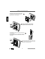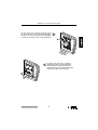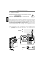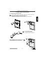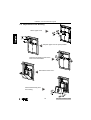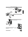
1
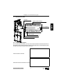
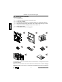
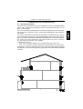
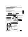
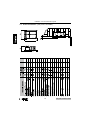
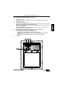
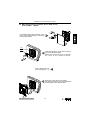
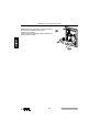
Installation, use and maintenance guide
INDEX
1 General Information
1.1
1.2
1.3
1.4
-
How to get through the User Guide correctly ................................... 2
Safety and Security Precautions ........................................................ 2
Identification Plate ..............................................................................3
Technical Assistance .......................................................................... 3
2 Unpacking and Handling
2.1 - Handling and Transport ...................................................................... 4
2.2 - How to unpack the Suction Unit ......................................................... 5
2.3 - Control of the Accessories ................................................................. 6
3 Description of the Suction Unit
3.1
3.2
3.3
3.4
3.5
3.6
3.7
3.8
-
Operating Principles ........................................................................... 7
Allowed and restricted Use ................................................................ 8
Compliance with EEC Regulations in force ....................................... 8
Security Provisions .............................................................................8
Noise Level .................................................................................
...........8
Construction Features .................................................................
.......... 9
Technical Features ...........................................................................10
Control Panel Description .................................................................11
4 Installation
4.1 - Safety Measures ...............................................................................12
4.2 - Place of Installation ..........................................................................12
4.3 - Installation Surface ...........................................................................12
4.4 - Installation Options ............................................................................12
4.5 - Wall Fitting with JOLLY BOX ....................................................
...........13
4.6 - Wall Fitting without JOLLY BOX .....................................15
4.7 - Electrical Connection .......................................................................20
5 How to use the Suction Unit
5.1 - Use of the Suction Unit ......................................................................21
5.2 - Starting of the Suction Unit .............................................................. 22
6 Maintenance
6.1 - Programmed Maintenance.................................................................23
6.2 - Dust Bag Replacement ................................................................... 24
7 Servicing
7.1 - Servicing Criteria ............................................................................. 27
8 Recommended Spare Parts
8.1 - Spare Parts List ............................................................................... 27
9 Dismantling and Disposal
9.1 - General Provisions ......................................................................... 27
10 Technical Problems
10.1 - Troubleshooting ............................................................................... 28
Jolly-Jolly Contact 01-04/01
1
Installation, use and maintenance guide
1 - GENERAL INFORMATION
1.1 How to get through the user guide correctly
The user guide of JOLLY and JOLLY CONTACT suction units is a fundamental document
issued by the manufacturer, and must be considered an integral part of the suction unit.
In case of resale, offering or lease to third parties, the user guide must be handed over
to the new user or to the new owner together with the original packing.
We recommend storing and keeping the user guide safely and carefully throughout the
entire operating life of the suction unit.
The main purpose of the user guide is to provide a correct knowledge of the suction
unit in order to get the best performances and keep the central suction unit at its best
operating and safety conditions.
It is absolutely forbidden to duplicate, copy or release any part of this user guide without
previous written authorization by TECNOPLUS s.r.l., owner of the SISTEM-AIR trade
mark. TECNOPLUS s.r.l. reserves the right to improve or modify the suction unit at
any time without previous notice.
1.2 Safety and security precautions
Read carefully any information detailed in this user guide about the installation, use
and maintenance of the suction unit.
Make sure that the suction unit has been correctly grounded.
Never use the suction unit improperly.
Instantly unplug the suction unit when:
the suction unit has been exposed to the inclemency of the weather or to excessive
moisture;
the suction unit has been damaged by an impact or when the packing/container
has been damaged;
the suction unit requires any repairing or overhauling.
Always wear protection gloves when carrying out any maintenance operation, when
replacing the dust bag, and when replacing/cleaning the motor filter.
Use only original SISTEM AIR spare parts.
Never use this suction unit to remove textile stuff, big-size bits and pieces of any material,
burning coals or ashes.
Never use this suction unit to remove liquids.
Use the suction unit only with the dust bag correctly assembled.
Use the suction unit only with the dust bag container correctly assembled.
Never use the suction unit without the lower cover.
Never block the external exhaust pipes of the air blown by the motor.
Never touch the suction accessories with any part of the body, when the unit is working.
Switch-off the suction unit if you are not going to use the suction unit for a short time.
If you are not going to use the suction unit for an extended period of time, it is advisable
to disconnect (JOLLY CONTACT only) from the mains power supply.
2
Jolly-Jolly Contact 01-04/01
Installation, use and maintenance guide
1.3 Identification plate
Unit type
Name of the Producer
SISTEM - AIR
Tel. +39-0381650082
Type:
ITALY
Fax. +39-0381650120
CE compliance
data
................
art. ...................
IPX 2
230 V~ 50/60 Hz 1000W 5 A
Mtr.
00 - 000000 - 00 - G
Serial number
Technical data of the electric motor
Item code
1.4 Technical Assistance
For any technical information you may need, call the Producer s Technical Service or
Authorized Center. Always specify the technical data indicated on the identification plate
as well as the serial number of the suction unit.
Technical Service Provider
Authorized Technical Assistance Center
Jolly-Jolly Contact 01-04/01
3
Installation, use and maintenance guide
2 - UNPACKING AND HANDLING
2.1 Handling and Transport
WEIGHT OF THE CARDBOARD BOX:..............................Kg 4,5
OVERALL DIMENSION OF THE CARDBOARD BOX:......cm 35x48x24
Arrange the packing (still-unopened) on the installation site following the instruction
detailed on the cardboard box.
Considering the small size and the limited weight, no special handling/transport means
are to be considered essential.
If necessary, use a trolley to move the unit or ask somebody to help you.
4
Jolly-Jolly Contact 01-04/01
Installation, use and maintenance guide
2.2 Unpacking
Arrange the cardboard box on the floor.
1 Follow the line indicated by the arrows and cut
the cardboard stripe containing the protection
polystyrene casing.
ATTENTION!: DO NOT DESTROY THE
CARDBOARD STRIPE SINCE IT CONTAINS
INSTALLATION INSTRUCTIONS AND
TEMPLATE.
Remove the cardboard stripe and
2
keep it safe, since it includes the
TEMPLATE and the installation
instructions.
NOTE: You can find detailed installation
instructions also in this user guide.
3
4
Open the cardboard box, lift the unit
and arrange it on the floor in
a horizontal position.
Take out all the accessories contained in the cardboard box and
dispose the packing material in compliance with the relevant
provisions in force.
ATTENTION !: Keep the cardboard stripe.
Jolly-Jolly Contact 01-04/01
5
Installation, use and maintenance guide
2.3 Control of the accessories
Check the contents:
1 - N° 1 suction unit.
2 - N° 1 frame provided with upper and lower covers.
3 - N° 1 dust bag container.
4 - N° 1 sponge for connection to JOLLY BOX casing or to air exhaust extension.
5 - N° 6 Ø 3x35 screws for fixing the suction unit to JOLLY BOX casing or to wall.
6 - N° 10 Ø 3x14 screws for fitting the frame to the suction unit.
7 - N° 5 dust bags (spare).
8 - N° 1 installation, use and servicing guide.
1
2
5
4
7
3
6
8
Check that the suction unit and the relevant accessories do correspond to the items
you have ordered:
Make sure that the suction unit and the relevant accessories have not been damaged
during the handling. In this case, you should inform immediately the Producer s Assistance
Service.
Jolly-Jolly Contact 01-04/01
6
Installation, use and maintenance guide
3 - DESCRIPTION OF THE SUCTION UNIT
3.1 Operating principles
JOLLY and JOLLY CONTACT suction units, suitable for any kind of residential building
(house, office, hotels, service buildings) consist of a SUCTION UNIT that it can be
build in external walls.
The units can be fitted in finished houses as well as in buildings still under construction.
JOLLY and JOLLY CONTACT suction units DO NOT REQUIRE any pipe network to
be installed.
The suction unit operates according to the principles of a traditional vacuum, with the
dust conveyed and collected in a dust bag assembled inside the unit. In this suction
unit the air and the dust particles are expelled (a standard feature in centralized systems).
The suction unit can be positioned in the external walls of any room, in order for
air, dust mites and micro-dust to be expelled.
To start the suction unit:
- Mod. JOLLY: press the start key on the control panel of the suction unit.
- Mod. JOLLY CONTACT: 1)Fit the coupling of the electrified hose into the special
housing of the suction unit. 2)Plug the suction unit to the main power supply by pressing
the start key on control panel. 3)Move to I the switch on the handle of the electrified
hose after .
Jolly-Jolly Contact 01-04
7
Installation, use and maintenance guide
3.2 Allowed and restricted use
SISTEM-AIR suction unit models «JOLLY » and « JOLLY CONTACT » have been
especially designed for wall installation to remove dust, small-sized solid bits and pieces
and dry materials.
The suction units have not been designed to remove textile stuffs, large-sized bits and
pieces, burning and hot materials.
Never remove liquids!
It is strictly forbidden to use these suction units in order to remove highly explosive
materials such as gun powder or inert materials for example, which can cause
dangerous chemical reactions if removed separately and then mixed up in the dust
container.
It is strictly forbidden to use these suction units in explosion hazard places or in places
where temperature, pressure and moisture are not in normal level.
The manufacturer declines all responsibility for damages to persons or objects due to
an improper use of the units.
Any use different from the ones expressly indicated is strictly
forbidden.
Any modification or adjustment of the suction unit in order to
remove a specific material must be approved by the builder, by
means of written authorization.
Any use different from the original is to be considered improper
and health risks for the user and damage to the suction unit cannot
be excluded.
3.3 Compliance with EEC Regulations in Force
SISTEM-AIR suction units mod. JOLLY and JOLLY CONTACT , which are the objects
of this user guide, fully comply with the requirements and the relevant provisions of the
EEC directives detailed hereunder:
98/37/CEE
Machine Directive (former 89/392/CEE)
73/23/CEE
Low Tension Directive (and following modifications)
89/336/CEE
Electromagnetic Consistency Directive (and following modifications)
3.4 Security Provisions
The suction units SISTEM-AIR mod. JOLLY and JOLLY CONTACT , which are the
objects of this user guide are equipped with:
- Motors provided with security thermal relay, which turns on and switches-off
automatically the suction units when the temperature exceeds specified level.
The motor restarts automatically after cooling.
- 10A 250V security motor delayed fuse for suction unit protection.
3.5 Noise level
The suction units never exceed 70 dB (A)
NOTE: the noise level refers to the noise issued by the equipment; it does not refer to
user s exposure, which can be affected by many other different factors.
8
Jolly-Jolly Contact 01-04/01
Installation, use and maintenance guide
3.6 Construction features (see picture)
The single-phase suction units for the civil sector included in the JOLLY product line
can be divided in two main categories:
JOLLY Line
JOLLY CONTACT Line
The two product lines, equipped with the same motor power, feature the same construction
technology and grant the same performances.
The JOLLY CONTACT line suction units are equipped with an electrified hose featuring
the start control on the handle.
Upper cover
Frame
Security fuse
(Jolly)
Start key
Plug-in key to mains power supply
(Jolly Contact)
Replacement dust bag led
Pipe positioning guide
Housing for lower cover
clamping hooks
Hose coupling
Motor filter
Lower cover clamping hooks
Container for dust bag
Lower cover
Sponge housing for
fitting without JOLLY BOX
Terminal board for electric connection
Pipe closing cover
Pressure switch
Plate indicating serial number
and technical data
Air exhaust pipe
Flange coupling for
JOLLY BOX casing
Jolly-Jolly Contact 01-04/01
9
Installation, use and maintenance guide
3.7 Technical features (see picture and table)
10
Jolly-Jolly Contact 01-04/01
Installation, use and maintenance guide
3.8 Control panel description (see picture)
1 - SECURITY FUSE
10A 250V motor security delayed-action fuse for protecting the equipment.
2 - START KEY (Jolly)
PLUG-IN KEY (Jolly Contact)
(Mod. JOLLY): Press the key: it switches on (red color) when the suction unit
has been activated and the unit starts operating
(Mod. JOLLY CONTACT): Press the key: it switches on (red color) when the
suction unit is plugged.
Plug the electrified hose into the relevant inlet and move to I the switch on
the hose handle to activate the unit.
3 - RED LED DUST BAG REPLACEMENT WARNING MESSAGE
Once the suction unit has been activated:
- Switched-off LED: the unit is working correctly.
- Flashing LED, fast flashing: the unit is working correctly.
- LED is permanently switched-on and unit is working but does not hoover
material:
THE DUST BAG IS OBSTRUCTED! REPLACE THE DUST BAG.
4 - Hose inlet.
1
2
3
4
Jolly-Jolly Contact 01-04/01
11
Installation, use and maintenance guide
4 - INSTALLATION
- ATTENTION THE UNDERMENTIONED OPERATIONS
MUST BE CARRIED OUT BY DULY QUALIFIED STAFF
4.1 Safety Measures
Suggestions for a correct installation in the relevant places are detailed hereunder:
During the installation of the unit a bipolar interrupter has to be installed before the unit
with a separation of the contacts of at least 3 mm.
Before the installation, specify the most suitable place inside the building and check
the building by carefully inspecting the following:
- There are no pipes (gas, electricity or water) spreading out in the walls.
- There are no bearing columns
- The air exhaust outlets on the external walls are not obstructed or blocked. They
can be easily drilled and their position does not create any problem to neighboring
structures.
4.2 Place of installation
Choose a space for installation so to allow the hose reaching the highest number of
spots. Consider the possibility of installing more units in a single building.
4.3 Installation surface
Leave free and well-lit space all around the suction unit to allow easy replacement of
the dust bag and trouble-free maintenance and r epair oper ations.
4.4 Installation options
Consider two different installation options:
- wall fitting with pre-installed JOLLY BOX casing (item number 8500.0).
- wall fitting without JOLLY BOX casing (finished houses).
The two following paragraphs illustrate the two different installation sequences.
For any question, do not hesitate to contact the Builder s Technical Service.
12
Jolly-Jolly Contact 01-04/01
Installation, use and maintenance guide
4.5 Wall fitting with pre-installed JOLLY BOX casing
(item number 8500.0)
(If installed) remove the protection cover
of the JOLLY BOX casing by unscrewing
the 6 locking screws.
1
(2)
(1)
2
Insert the sponge (1) in the round housing
(2) of the Jolly Box casing.
NOTE: the sponge must not go beyond
the edge of the special housing.
Plug-in the suction unit
(see paragraph 4.7)
4
Jolly-Jolly Contact 01-04/01
3
Arrange the Jolly suction unit inside
the casing (Jolly Box); pay special attention
to the position of the electric cable.
13
Installation, use and maintenance guide
Put the Jolly suction unit to the wall;
use ONLY the 6 Ø 3x35 mm screws
delivered with the suction unit.
5
6
5
N°6 Ø 3 x 35 mm
1
4
2
3
10
N°10 Ø 3 x 14
9
1
8
7
2
6
6
Screw the special frame to the
Jolly suction unit; use ONLY
the 10 Ø 3x14 mm screws included
in the suction unit box.
3
4
5
Fix the switch cover. Arrange one of the two side
pins in the housing and position the second one;
push it gently until it engages.
A weak click confirms the correct assembly.
7
1
2
Arrange the dust bag container.
8 Arrange the lower cover by positioning
the two guides in the slots of the frame.
Push gently the cover towards the frame
until the two upper hooks engage.
1
2
14
Jolly-Jolly Contact 01-04/01
Installation, use and maintenance guide
4.6 - Wall fitting without JOLLY BOX casing (finished houses)
ATTENTION: before installing, read carefully the installation instructions detailed in
paragraphs 4.1, 4.2, 4.3 and 4.4.
Cut the edge of the cardboard stripe; use a pair
of scissors and carefully follow the dotted line. 1
Once you have finished the cutting operation,
you have got your TEMPLATE!
Arrange the template on the wall;
draw the outline of the template
and the position of the air exhaust outlet.
2
1
2
Ø 10
3
Jolly-Jolly Contact 01-04/01
Drill a pre-centering hole Ø 10
(GO BEYOND THE WALL) in the spot
you have previously marked.
15
Installation, use and maintenance guide
Drill by following the outer edge you have
previously drawn. Use an angle grinder
(shown in the picture) to drill accurately.
4
Make a hole in the wall for the housing
of the Jolly suction unit.
IMPORTANT: Depth of the housing: 15 cm
5
Enlarge to Ø 90 the Ø 10 hole
6
previously drilled; use a Ø 90 core drill.
IMPORTANT: if possible, enlarge the hole
by drilling half from outside and half from
inside.
Ø 90
Ø 90
50%
50%
7
The picture shows the finished housing
for the Jolly suction unit.
16
Jolly-Jolly Contact 01-04/01
Installation, use and maintenance guide
Put the Jolly suction unit into the housing,
position it on the wall and check the correct
perpendicularity with reference to the floor.
Use a pencil and draw the position of the six
holes to be drilled for fixing the suction unit to
the wall.
8
90°
90°
6
5
1
4
2
3
Remove the Jolly suction unit from the housing
9 and drill the 6 holes previously sketched.
Drill the holes by paying attention to the type of wall
you are drilling and to the screw anchor to be used.
6
5
N°6
1
4
2
3
(3)
Fit the connection sponge (1) in the round
10
housing (2) around the pipe union of the air
exhaust (3) of the Jolly suction unit.
Fit the extension (4) in the sponge; check that
the cover of the exhaust pipe union is not
obstructed.
NOTE: when installing the suction unit into
thick walls, you probably need to fit more than
one extension; another extension can be
coupled to the first one to obtain the desired
measure.
Plug-in the unit
(see paragraph 4.7)
Jolly-Jolly Contact 01-04/01
11
17
(2)
(1)
(4)
art. 8510.0
Installation, use and maintenance guide
Arrange the Jolly unit in the housing and fit
the extension in the Ø 90 hole by paying
great attention to cable position.
12
6
Fix the Jolly suction unit to the wall.
13 Use ONLY the 6 Ø 3x35 mm screws
delivered with the suction unit.
5
N°6 Ø 3 x 35 mm
1
4
2
3
Use adhesive or silicone to seal the external end
of the extension.
If necessary, trim the extension section,
which protrudes from the wall and close with
a vent grid.
14
10
N°10 Ø 3 x 14
9
Screw the special frame to the Jolly suction
15 unit; use ONLY the 10 Ø 3x14mm screws
included in the cardboard box.
1
8
7
2
6
3
4
5
18
Jolly-Jolly Contact 01-04/01
Installation, use and maintenance guide
Fix the cover of the switch. Arrange one of
the two side pins in the housing and position 16
the second one; push it gently until it engages.
A weak click confirms the correct assembly.
1
2
17
Arrange the dust bag container.
Arrange the lower cover by positioning
the two guides in the slots of the frame.
Push gently the cover towards the frame
until the two upper hooks engage.
1
2
Jolly-Jolly Contact 01-04/01
19
Installation, use and maintenance guide
4.7 Electrical connection
IMPORTANT!= Always unplug the suction unit before carrying
out any operation.
ATENTION= The installation must be carried out by duly
qualified staff only!
Before plugging the suction unit, make sure that the main power supply corresponds
to the power supply indicated on the serial number plate arranged on the rear side of
the suction unit (see the serial number plate detailed in paragraph 1.3). The relevant
data are specified also in paragraph 3.7- Technical Features .
The Builder declines all responsibility for damages to person or objects due to an electric
system connection, which does not comply with the regulations in force.
Follow the instructions to carry out this operation correctly (see picture below).
1 - Connect the power supply cables L - N to terminals 1 and 2, as shown in picture
(see below).
230V~
N
L
1.5 mm2
1
2
230V~
20
IPX 2
Jolly-Jolly Contact 01-04/01
Installation, use and maintenance guide
5 - HOW TO USE THE SUCTION UNIT
5.1 How to use the suction unit
1
Lift the upper cover by pressing gently the knurled center (A).
Press gently to release the closing hook of the cover.
Press gently until a click confirms the release.
Release the cover (B) and open it until it stops in open position (C).
C
A
B
2
Fit the opposite end of the hose in the suction
inlet; pay attention to the correct position
3
of the guide between the hose and the unit.
Jolly-Jolly Contact 01-04/01
21
Fit the accessory suitable
for the cleaning operation
you want to carry out in the hose.
Installation, use and maintenance guide
5.2 Starting of the suction unit
Press the start push-button.
A red LED switches on.
1
(JOLLY MODEL)
The suction unit switches on and starts
hoovering.
(JOLLY CONTACT MODEL)
The red start push-button switches on
and confirms that the suction unit
is plugged to the power supply.
2
JOLLY CONTACT MODEL ONLY
Move to I the switch at the end
of the electrified hose.
The suction unit switches on
and starts hoovering.
After finishing the cleaning operations, repeat the sequence in reverse
to switch off the suction unit.
22
Jolly-Jolly Contact 01-04/01
Installation, use and maintenance guide
6 - MAINTENANCE
-ATTENTIONBEFORE CARRYING OUT ANY MAINTENANCE OPERATION, ALWAYS
UNPLUG THE SUCTION UNIT FROM THE POWER SUPPLY AND CHECK
THAT THE RED START PUSH-BUTTON IS SWITCHED OFF. ALWAYS WEAR
PROTECTION GLOVES AND GOGGLES.
6.1 Programmed maintenance
In order to keep the system perfectly operating and to avoid possible mechanic trouble,
the user must overhaul the whole system at precise time intervals.
The JOLLY and JOLLY CONTACT suction units are equipped with a maintenance
control system.
In particular, the system indicates when the dust bag must be replaced by means of a
red led assembled on the front side of the suction unit.
IMPORTANT ! = The dust bag must be replaced if the red led remains lit up when
the unit is activated but does not suck.
- Periodically clean the motor filter with running water. Wait until the unit is perfectly
dry before assembling.
- Periodically check that the exhaust air extension outside the wall is not covered or
obstructed.
- Periodically clean the external casing of the suction unit using a smooth cloth dampened
with water and some neutral soap.
- Attention : Be sure to use only water or water with neutral soap when cleaning
the suction unit. Wait until the unit is perfectly dry prior to start it.
Jolly-Jolly Contact 01-04/01
23
Installation, use and maintenance guide
6.2 Replacement of the dust bag
Lift the upper cover.
A
1
B
2
2
Stop the upper cover in open position.
Press the two closing hooks of the
lower cover downwards.
4
3
Remove the lower cover .
Detach the dust bag from
the housing
5
B
A
24
Jolly-Jolly Contact 01-04/01
Installation, use and maintenance guide
Remove the dust bag.
6
!
Insert a new dust bag in the container.
7 ATTENTION ! = Insert the new dust bag
correctly in the special container guides.
8
Position the dust bag container by correctly
coupling the bag fitting to the internal pipe union.
Check that the dust bag does not appear
under the container!
C
B
A
Check if the bag is correctly positioned and
the bag fitting perfectly suits the pipe union
by gently moving the whole container
perpendicularly.
Jolly-Jolly Contact 01-04/01
25
9
Installation, use and maintenance guide
Reassemble the cover of the dust bag by fitting
the two lower guides into the small
cavities on the frame.
Press the cover towards the frame until the two
closing hooks engage.
10
A
B
26
Jolly-Jolly Contact 01-04/01
Installation, use and maintenance guide
7 - SERVICING
7.1 Servicing Criteria
It is strictly forbidden to carry out, any maintenance or servicing operation not expressly
authorized in this user manual.
Only duly qualified technical assistance providers can carry out any maintenance or
repair operations.
The guarantee will not apply in case of interventions carried out by non-authorized staff
and the manufacturer cannot be considered responsible for possible injuries to persons
and damages to things resulting from this kind or intervention.
8 - RECOMMENDED SPARE PARTS
8.1 Spare parts list
It is advisable to stock the spare parts more subject to wear.
In order to grant the best and long-lasting performance, we suggest using only original
SISTEM-AIR spare parts.
Description
Quantity
Spare Part Code
Dust bag package
1 pack.
(5 dust bags)
8402.0
- Jolly
- Jolly Contact
Motor protection
filter
1
8406.0
- Jolly
- Jolly Contact
Suction Unit Model
9 - DISMANTLING AND DISPOSAL
9.1
General instructions
When dismantling the suction system, dispose appropriately of used parts or material,
which could endanger human health or well-being as well as the environment if handled
improperly.
You must be acquainted with sites/companies to collect and dispose of used parts and
materials.
The disposal and/or recycling of any part of the suction unit must be carried out in
compliance with legal regulations in force.
Jolly-Jolly Contact 01-04/01
27
Installation, use and maintenance guide
10 - TECHNICAL PROBLEMS
10.1 Troubleshooting
Problem
The suction unit
does not start
Possible causes
Possible corrective measure
The power supply
is switched off
Switch on the power supply
The start push-button of the
unit is not activated
Press the start push-button
The electrified hose is plugged Plug correctly the electrified
incorrectly (Jolly Contact only) hose in the housing
The thermal relay of the motor Allow several minutes for
triggers
motor cooling
Weak air suction
Fuse burnt-out
Unscrew the fuse cover
and replace it
Hose and cleaning
accessories broken
Check if the hose and the
accessories are integral and
replace them if needed
The dust bag needs
to be replaced
Replace the dust bag
The dust bag is positioned
incorrectly in the housing
Check the correct position of
the bag in the container guides
and of the fitting of the pipe
union
Dust bag worn
Replace the dust bag
The fitting of the lower cover
is damaged or incorrectly
positioned
Check if the fitting is integral
and correctly positioned
The motor protection filter
is dirty
Check and clean if needed
Hose or accessories
obstructed
Check and clean if needed
The lower cover is incorrectly Check and close the cover
assembled
correctly
The air exhaust is obstructed
28
Contact the Technical Service
Jolly-Jolly Contact 01-04/01