1
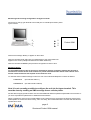
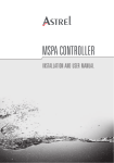
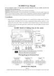
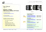
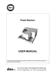
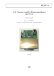
Shortened Pocket GSM user manual
FOR USING JUST THE DIGITAL INPUTS AND OUTPUTS
4 digital inputs and 2 digital outputs
?
rev. 2.4/dco 03/2005
page 1
Shortened Pocket GSM manual
TECHNICAL FEATURES
Power Supply From 5 to 32 Vdc
Size 87x75x25mm
Weight About 130gr
Operating Temperature From -5°C to +45°C
Storage Temperature From -20°C to +70°C
Data Interface RS232 9pin (V24/V28)
Antenna Connector Type SMA female connector
I/O and power connections via mini-fit automotive connector, we supply a flying lead.
The Pocket gsm has 4 digital inputs and 2 digital outputs, which are used for sms (text
message communications).
WARNINGS
Safety
Read carefully these instructions and notes before powering Pocket GSM. For each situation
Please follow the specific instructions.
Pocket GSM is a low power radio transmitter and receiver. When it is ON, it sends and receives radio frequency
(RF) signals.
Pocket GSM produces magnetic fields. Do not place it next to magnetic media such as
floppy disks, tapes, etc. . Operating your modem close to other electrical equipment such
As television, phone, radios and personal computer, may cause interference.
Interference
Pocket GSM, like all wireless devices, is subject to interferences that may reduce its performance.
Road Safety
Do not use Pocket GSM while driving. In case of use on cars, it is necessary to check that electronic equipment
is shielded against RF signal. Do not place Pocket GSM over the air bag or in the air bag deployment area.
Aircraft Safety
Switch off Pocket GSM in aircraft by disconnecting the Power cable. Using GSM devices on aircraft is illegal.
Hospital Safety
Do not use Pocket GSM near health equipment, especially pacemaker and hearing aids, to avoid potential
interferences. Pocket GSM is a not mobile phone; do not use it in direct contact with the human body. Switch it
off in hospitals, and medical center. Hospitals or health care facilities may be using equipment that could be
sensitive to external RF energy.
Explosive Materials
Do not use Pocket GSM in refueling points, near fuel or chemicals. Do not use the Pocket GSM where blasting is
in progress. Observe restrictions, and follow any regulation or instruction.
Do not use Pocket GSM in direct contact with the human body; do not touch the antenna if not necessary when
the phone is in use. Use approved accessories and batteries only. Do not connect incompatible products.
page 2
Shortened Pocket GSM manual
INSTALLATION
Installation is quick and simple. Configuration is done by sending the unit text messages from
a mobile phone – please refer to the relevant section.
Antenna
Normally the antenna comes with the Pocket GSM and screws directly onto the unit via the SMA type connector.
If the modem is to be mounted in a metal enclosure or an area where the mobile signal is poor then we have
available a range of alternative antennas.
Connection of the external antenna
To connect the external antenna go on as follows:
1. Turn off your Pocket GSM by disconnecting the power connector.
2. Connect the SMA male connector to the external antenna of Pocket GSM, screwing it clockwise.
3. Place the antenna and check there is a good quality signal.
Attention: the power supply voltage must not exceed the indicated maximum value as
this may cause damage to the product.
Connections
Power connections are presented on the 12 way minifit automotive connector on the unit.
Your Pocket GSM will come complete with a flying lead to simplify this connection process.
Cable Colour
Violet
Orange
Brown
Pink
Light Blue
Black
Dark Blue
Red
Green
Grey
Yellow
White
Pin
6
12
5
11
4
10
3
9
2
8
1
7
Description
Digital input 1
No Connection
Digital input 2
No Connection
Digital input 3
Ground
Digital input 4
Power supply (5 to 32 Vdc)
Digital Output 1
No connection
Digital Output 2
No connection
Power should be connected to terminals 9 (5 to 32 Vdc) and 10 (ground).
page 3
Shortened Pocket GSM manual
Connection of the Digital Inputs and Outputs
The inputs are made ‘on’by making a connection between the relevant pin and ground.
e.g.
6
Digital input 1
POCKET GSM
10
Ground (0v)
The outputs are Open Collectors (NPN).
The maximum collector emitter voltage (Vce) is 45 volts, and Maximum collector current (Ic) is 500mA.
+12V
Load
1
Pocket GSM
10
0v
SIM CARD
The Pocket GSM supports plug-in SIM cards.
To prevent damaging or losing information avoid touching the gold area on
the sim.
Attention: Check with your GSM provider if your SIM is enable for data
and fax traffic, if not ask him for this service, he will give you other two
numbers (one for data calls and the other for fax calls). If you are using
‘pay as you go’ensure that you have credit on your sim, and that you
do not have a minimum usage to maintain operation.
Ensure that your sim card is not protected by a PIN code.
page 4
Shortened Pocket GSM manual
Insert the SIM
1. Remove the SIM carefully from the credit card sized holder
2. Turn off Pocket GSM, by disconnecting the power connector.
3. Discover the SIM slot and press on the release pin with a finger or a pencil.
4. Insert the SIM card into the holder. Be sure the angled corner is top right.
5. Close the SIM holder and press it up to the end. Do not force the SIM holder
and verify the correct position. .
Checking the signal strength
Using a cellular phone
Insert the SIM of the Pocket GSM in a cellular phone and check the quality of the signal.
Through the Led STATUS
Power on the modem and verify the STATUS Led. If it is red blinking, it means the modem is recognized by the
GSM network. In this way you can check the signal but not its quality.
Even if you see the STATUS Led blinking, it may not be sufficient for reliable operation.
Alternatively…
Once you have programmed the unit send the following message to the device
#CONFIG1#
and the unit will respond with an indication of signal strength
LED INDICATORS
Through the two led indicators you can monitor the status of the Pocket GSM:
POWER
OFF No power supply
ON Power supply on
STATUS
ON Pocket GSM is in one of the following status:
- network search mode;
- SIM card not present;
- PIN not inserted;
- emergency mode.
SLOW BLINKING Pocket GSM detected by the GSM network
FAST BLINKING Pocket GSM connected to another device
page 5
Shortened Pocket GSM manual
Programming the Pocket GSM to send Text message alarms
The Pocket GSM is programmed by sending it sms (text) messages. It is important to decide whether the alarms
will be triggered during a transition (on to off, or off to on) or whether a high state (on) only. Having established a
telephone number for the unit (given with the SIM from you GSM provider) the procedures are as follows:
It is important to follow the procedure in the correct order.
1) Configure the access list
THE FORMAT OF THE MESSAGE IS VITAL. IF YOU DO NOT GET THE FORMAT RIGHT YOU WILL NEED
TO UNLOCK THE UNIT USING A PC WITH HYPERTERMINAL OR RETURN TO POWELECTRICS.
The access list is a set of numbers held by the Pocket GSM. In order to program the unit the text messages
must be sent from a mobile phone number that is held within the Pocket GSM.
(Cellular phones which can change the configuration and request data from the modem )
Send to the modem an SMS message containing the access list.
#ACCLIST#NTEL1#NTEL2#NTEL3#NTEL4#NTEL5#NTEL6#
It is possible to insert up to 6 telephone numbers
Note the numbers must be complete with international codes prefixed with the + sign
i.e. +44605786515 etc, for example
#ACCLIST#+447966368099#
will program the number 07966 368099 into the access list and clear all other numbers in the access list.
2) Give the Pocket GSM an Identity
Send an SMS message from a cellular phone to allocate the Pocket Modem a name (in this case we have called
it PumpNo1). Maximum length is 20 characters.
#0#PumpNo1#
3) Program the Digital Inputs
Send an SMS message to the unit labeling each of the 4 alarms inputs. In this case we have called the 1st alarm
‘Alarm 1’and if it is in the ON (S) state it will send a message to all 3 telephone numbers given. The inputs can
only be configured from a number that is on the access list.
#1#Alarm 1#S#+44678905677#+4465789457#+44678594568#
The maximum length of the name is 20 characters.
We now add the 2nd input and call it “Overload”which if any change of state (T) takes place will send an alarm
to the 3 telephone numbers.
#2#Overload#T#+44678905677#+4465789457#+44678594568#
This procedure is repeated for the other 2 inputs of the Pocket Modem.
page 6
Shortened Pocket GSM manual
‘S’and ‘T’set how the Pocket GSM will send an alarm.
‘S’– if an input goes High (1), then a text message is sent as programmed. If the input returns to a Low (0) state
then no further message is sent.
‘T’– this refers to Transition – so each time the input changes from a high to a low, or a low to a high, a text
message is sent.
4) Configure the Outputs
The outputs can only be set by numbers programmed into the access list. The output state can only be changed
by authorised users.
#5# refers to output 1
#6# refers to output 2
The output is given a name (for example Pump1) with a maximum of 20 characters, and you send a message
detailing the name and which phone numbers can change the output state. e.g.
#5#Pump1#+44678905677#+4465789457#+44678594568#+445673445#
#6#Pump2#+44678905677#+4465789457#+44678594568#
So to switch on output 1 (pump 1) you would send:
#Pump1 ON#
and to switch it off you would send:
#Pump1 OFF#
The Pocket GSM will respond with a text message so you know the action has taken place.
5)
Check the configuration is OK
To verify the settings of the unit send the
#Config#
message from one of the authorized cellular phones. The unit will then send the complete configuration.
6)
Delete the configuration
To delete the configuration send the message
#99#
to the unit from an authorised number.
page 7
Shortened Pocket GSM manual
Monitoring and canceling configuration via Hyper Terminal
Connect a PC using hyper terminal to the serial port at 115200 bps and then power
up the modem.
2
3
5
2
3
5
Pocket GSM
Wait for the message “Ready”to appear on the screen.
With the command ATFLASH (CR) a complete listing of the configuration will
appear on the screen (Telephone Numbers and Alarm status etc)
With the command ATRESET (CR) the entire configuration is reset to zero.
Resetting Alarms
To avoid malfunctioning due to spurious or transitional changes of state the modem will generate a
maximum of 5 alarms for the same contact in a period of 60 minutes after which it will cease to send
alarms unless the 60 mins has expired or the contact is reset.
To reset the alarm an SMS message is sent from one of the authorised telephone numbers as follows:
#1#RESET#
(this will reset Alarm 1)
#99#RESET#
(this will reset all 4 alarms)
Note it is not currently possible to configure the unit via the hyper terminal. This
must be done by sending an SMS message from a cellular phone.
We are able to supply special versions of the Pocket GSM with different operational parameters and functions. If
you have a special then please refer to additional documentation.
When a message is sent from the Pocket GSM the unit ensures that it is received by the Service Centre for the
GSM operator. If the service centre is busy, full or not ready, the Pocket GSM waits 1 minutes and resends and
repeats this 3 times.
page 8
Shortened Pocket GSM manual