1
REJ10B0060-0600
HI7000/4 Series
(HI7000/4 V.2.02, HI7700/4 V.2.02, and HI7750/4 V.2.02)
User’s Manual
Renesas Microcomputer Development Environment System
Rev.6.00
Revision date: Jan. 04, 2006
www.renesas.com
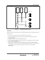
Keep safety first in your circuit designs!
1. Renesas Technology Corp. puts the maximum effort into making semiconductor products better and
more reliable, but there is always the possibility that trouble may occur with them. Trouble with
semiconductors may lead to personal injury, fire or property damage.
Remember to give due consideration to safety when making your circuit designs, with appropriate
measures such as (i) placement of substitutive, auxiliary circuits, (ii) use of nonflammable material or
(iii) prevention against any malfunction or mishap.
Notes regarding these materials
1. These materials are intended as a reference to assist our customers in the selection of the Renesas
Technology Corp. product best suited to the customer's application; they do not convey any license
under any intellectual property rights, or any other rights, belonging to Renesas Technology Corp. or
a third party.
2. Renesas Technology Corp. assumes no responsibility for any damage, or infringement of any thirdparty's rights, originating in the use of any product data, diagrams, charts, programs, algorithms, or
circuit application examples contained in these materials.
3. All information contained in these materials, including product data, diagrams, charts, programs and
algorithms represents information on products at the time of publication of these materials, and are
subject to change by Renesas Technology Corp. without notice due to product improvements or
other reasons. It is therefore recommended that customers contact Renesas Technology Corp. or
an authorized Renesas Technology Corp. product distributor for the latest product information
before purchasing a product listed herein.
The information described here may contain technical inaccuracies or typographical errors.
Renesas Technology Corp. assumes no responsibility for any damage, liability, or other loss rising
from these inaccuracies or errors.
Please also pay attention to information published by Renesas Technology Corp. by various means,
including the Renesas Technology Corp. Semiconductor home page (http://www.renesas.com).
4. When using any or all of the information contained in these materials, including product data,
diagrams, charts, programs, and algorithms, please be sure to evaluate all information as a total
system before making a final decision on the applicability of the information and products. Renesas
Technology Corp. assumes no responsibility for any damage, liability or other loss resulting from the
information contained herein.
5. Renesas Technology Corp. semiconductors are not designed or manufactured for use in a device or
system that is used under circumstances in which human life is potentially at stake. Please contact
Renesas Technology Corp. or an authorized Renesas Technology Corp. product distributor when
considering the use of a product contained herein for any specific purposes, such as apparatus or
systems for transportation, vehicular, medical, aerospace, nuclear, or undersea repeater use.
6. The prior written approval of Renesas Technology Corp. is necessary to reprint or reproduce in
whole or in part these materials.
7. If these products or technologies are subject to the Japanese export control restrictions, they must
be exported under a license from the Japanese government and cannot be imported into a country
other than the approved destination.
Any diversion or reexport contrary to the export control laws and regulations of Japan and/or the
country of destination is prohibited.
8. Please contact Renesas Technology Corp. for further details on these materials or the products
contained therein.
Rev.6.00
REJ10B0060-0600
1.
2.
3.
4.
5.
6.
7
TRON is an acronym of “The Realtime Operating system Nucleus”, ITRON is an acronym of the
“Industrial TRON”, and µITRON is an acronym of the “Micro Industrial TRON”.
TRON, ITRON, and µITRON are the names of computer specifications and do not indicate a specific
group of the commodity or the commodity.
The µITRON4.0 specification is open realtime-kernel specification defined by the TRON association.
The specification of µITRON4.0 can be downloaded from the TRON association homepage
(http://www.assoc.tron.org).
The copyright of the µITRON specification belongs to the TRON association.
Microsoft® Windows® 98, Microsoft® Windows® Millennium Edition (Windows® Me) operating
system, Microsoft® Windows NT® operating system, Microsoft® Windows® 2000 operating system,
and Microsoft® Windows® XP operating system are registered trademarks of Microsoft Corporation in
the United States and/or other countries.
SuperHTM is a trademark of Renesas Technology Corp.
All other product names are trademarks or registered trademarks of the respective holders.
Rev.6.00
REJ10B0060-0600
Preface
This manual describes how to configure systems using the HI7000/4, HI7700/4, and HI7750/4
(hereinafter collectively referred to as the HI7000/4 series) embedded realtime multitasking
operating systems based on µITRON4.0 specifications.
Please read this manual and the related manuals listed below before using the HI7000/4 series to
fully understand the operating system.
This user's manual contains the following five sections and appendixes:
Section 1
Section 2
Section 3
Section 4
Section 5
Appendixes
Introduction to HI7000/4 series: general description of HI7000/4 series systems
Kernel: overview of HI7000/4 series kernel functions.
System calls: overview of HI7000/4 series kernel system calls.
Applications: creating applications in C using sample programs
System configuration method: configuring the system using the configurator
List of service call function codes, error references, user and kernel work area
calculations, timer drivers, optional functions of HI7700/4 (optimized timer driver
and DSP standby control function), note on FPU, and modified functions in the
new version of the product.
The other relevant manuals are listed below:
• Release Notes provided for the product
• Manuals provided for the SuperH™ RISC engine C/C++ compiler package
• The hardware manual and programming manual of the SuperH™ microcomputer in use
Renesas Technology Homepage:
Various support information is available on the Renesas Technology homepage:
http://www.renesas.com/en/tools/
Rev.6.00 i
REJ10B0060-0600
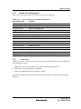
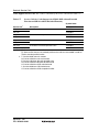
Preface
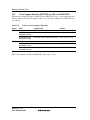
Abbreviations of products
Product Name
Description
HI7000/4 series
Abbreviation of HI7000/4, HI7700/4, and HI7750/4
DX
Abbreviation of Debugging Extension
HEW
Abbreviation of High-performance Embedded Workshop, which is an
integrated development tool.
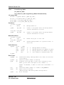
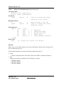
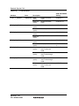
Symbols used in this manual have the following meanings:
H' and D':
nnnn:
???
CFG_MAXTSKID:
Rev.6.00 ii
REJ10B0060-0600
For hexadecimal integers, prefix H' is attached. For decimal integers,
prefix H' is attached. If no prefix is attached, a decimal integer is
assumed.
Bold-faced-italic nnnn is the CPU name used for the sample file
name.
Example: The timer driver file name is nnnn_tmrdrv.c in this
manual, but the actual timer driver file for SH7708 is 7708_tmrdrv.c.
??? is used for the file name in the HI7700/4 and HI7750/4. For big
endian and little endian, big and little are used instead of ???,
respectively.
A variable name beginning with CGF_ is specified for the
configurator by the user to use the configurator. For details, refer to
section 5.4.6, Configurator Settings, and the configurator on-line
help.
Contents
Section 1
1.1
1.2
1.3
1.4
1.5
Introduction .............................................................................................1
Overview .......................................................................................................................1
Features .........................................................................................................................1
Operating Environment .................................................................................................3
Installation.....................................................................................................................3
Target Product of This Manual......................................................................................4
Section 2
2.1
2.2
2.3
2.4
Kernel .......................................................................................................5
Overview .......................................................................................................................5
Functions .......................................................................................................................5
Processing Units and Precedence ..................................................................................6
System State ..................................................................................................................7
2.4.1
2.4.2
2.4.3
2.5
2.6
Objects...........................................................................................................................9
Tasks .............................................................................................................................9
2.6.1
2.6.2
2.6.3
2.6.4
2.6.5
2.6.6
2.6.7
2.6.8
2.6.9
2.6.10
2.7
2.8
2.9
2.10
2.11
2.12
2.13
2.14
2.15
Overview .......................................................................................................................... 37
Controlling Fragmentation of Free Space ........................................................................ 40
Management of Variable-Size Memory Pool ................................................................... 42
Time Management.......................................................................................................43
2.16.1
2.16.2
2.16.3
2.16.4
2.17
Task State and Transition ................................................................................................. 11
Task Creation ................................................................................................................... 13
Task Initiation................................................................................................................... 13
Task Scheduling ............................................................................................................... 14
Task Termination and Deletion......................................................................................... 15
Task Stack ........................................................................................................................ 15
Shared Stack Function...................................................................................................... 16
Task Execution Mode ....................................................................................................... 18
Exclusive Control............................................................................................................. 18
Task Event Flags .............................................................................................................. 19
Task Exception Processing..........................................................................................20
Semaphore...................................................................................................................22
Event Flag ...................................................................................................................24
Data Queue..................................................................................................................26
Mailbox .......................................................................................................................28
Mutex ..........................................................................................................................30
Message Buffer ...........................................................................................................32
Fixed-Size Memory Pool.............................................................................................35
Variable-Size Memory Pool ........................................................................................37
2.15.1
2.15.2
2.15.3
2.16
Task Context State and Non-Task Context State ................................................................ 8
Dispatch-Disabled State/Dispatch-Enabled State............................................................... 8
CPU-Locked State/CPU-Unlocked State ........................................................................... 9
Cyclic Handler ................................................................................................................. 44
Alarm Handler.................................................................................................................. 46
Overrun Handler............................................................................................................... 47
Notes on Time Management ............................................................................................ 48
System State Management ..........................................................................................49
2.17.1
2.17.2
System Down ................................................................................................................... 49
Service Call Trace Function ............................................................................................. 50
Rev.6.00 i
REJ10B0060-0600
Contents
2.18
Interrupt Management and System Configuration Management ................................ 52
2.18.1
2.18.2
2.18.3
2.18.4
2.18.5
2.19
2.20
2.21
2.22
2.23
2.24
Service Call Management ........................................................................................... 59
Cache Support (only for HI7700/4 and HI7750/4) ..................................................... 60
Kernel Idling ............................................................................................................... 62
Pre-fetch Function (only for HI7700/4 and HI7750/4) ............................................... 62
Optimized Timer Driver (only for HI7700/4) ............................................................. 62
DSP Standby Control Function (only for HI7700/4) .................................................. 62
Section 3
3.1
3.2
Service Calls ...........................................................................................63
Overview..................................................................................................................... 63
Service Call Interface.................................................................................................. 64
3.2.1
3.2.2
3.2.3
3.2.4
3.2.5
3.2.6
3.3
3.4
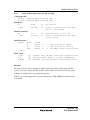
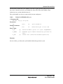
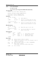
Create Task ....................................................................................................................... 76
Delete Task (del_tsk) ........................................................................................................ 80
Initiate Task (act_tsk, iact_tsk) ......................................................................................... 81
Cancel Task Initiation Request (can_act, ican_act) .......................................................... 82
Start Task (Start Code Specified) (sta_tsk, ista_tsk) ......................................................... 83
Exit Current Task, Exit and Delete Current Task (ext_tsk), (exd_tsk) .............................. 84
Terminate Task (ter_tsk) ................................................................................................... 86
Change Task Priority (chg_pri, ichg_pri) ......................................................................... 87
Refer to Task Priority (get_pri, iget_pri) .......................................................................... 88
Refer to Task State (ref_tsk, iref_tsk) ............................................................................... 89
Refer to Task State (Simple Version) (ref_tst, iref_tst)..................................................... 93
Change Task Execution Mode (vchg_tmd)....................................................................... 95
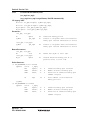
Task Synchronization.................................................................................................. 96
3.5.1
3.5.2
3.5.3
3.5.4
3.5.5
3.5.6
3.5.7
3.5.8
3.5.9
3.5.10
3.6
C Language API ............................................................................................................... 64
Assembly Language API .................................................................................................. 66
Guarantee of Register Contents after Issuing Service Call ............................................... 67
Return Value of Service Call and Error Code ................................................................... 69
System State and Service Calls......................................................................................... 69
Service Calls not in the μITRON4.0 Specification........................................................... 72
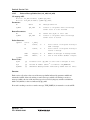
Service Call Description Form.................................................................................... 73
Task Management ....................................................................................................... 74
3.4.1
3.4.2
3.4.3
3.4.4
3.4.5
3.4.6
3.4.7
3.4.8
3.4.9
3.4.10
3.4.11
3.4.12
3.5
Resetting the CPU and Initiating the Kernel..................................................................... 53
Interrupt Handlers............................................................................................................. 54
Disabling Interrupts.......................................................................................................... 55
Kernel Interrupt Mask Level (CFG_KNLMSKLVL): ...................................................... 57
CPU Exception................................................................................................................. 58
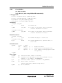
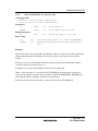
Sleep Task (slp_tsk, tslp_tsk) ........................................................................................... 98
Wakeup Task (wup_tsk, iwup_tsk) ................................................................................... 99
Cancel Wakeup Task (can_wup, ican_wup) ................................................................... 100
Release WAITING State Forcibly (rel_wai, irel_wai) .................................................... 101
Suspend Task (sus_tsk, isus_tsk).................................................................................... 102
Resume Task Force, Task to Resume (rsm_tsk, irsm_tsk, frsm_tsk, ifrsm_tsk) ............. 103
Delay Task (dly_tsk)....................................................................................................... 104
Set Task Event Flag (vset_tfl, ivset_tfl).......................................................................... 105
Clear Task Event Flag (vclr_tfl, ivclr_tfl)....................................................................... 106
Wait Task Event Flag (vwai_tfl, vpol_tfl, vtwai_tfl) ...................................................... 107
Task Exception Processing Functions....................................................................... 109
3.6.1
3.6.2
3.6.3
3.6.4
3.6.5
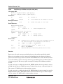
Define Task Exception Processing Routine (def_tex, idef_tex)...................................... 111
Request Task Exception Processing (ras_tex, iras_tex) .................................................. 113
Disable Task Exception Processing (dis_tex) ................................................................. 114
Enable Task Exception Processing (ena_tex) ................................................................. 115
Refer To Task Exception Processing Disabled State (sns_tex) ....................................... 116
Rev.6.00 ii
REJ10B0060-0600
Contents
3.6.6
3.7
3.7.1
3.7.2
3.7.3
3.7.4
3.7.5
3.8
3.9.4
3.9.5
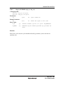
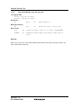
Create Fixed-Size Memory Pool .................................................................................... 176
Delete Fixed-Size Memory Pool (del_mpf) ................................................................... 179
Get Fixed-Size Memory Block (get_mpf, pget_mpf, ipget_mpf, tget_mpf) .................. 180
Release Fixed-Size Memory Block (rel_mpf, irel_mpf) ................................................ 182
Refer to Fixed-Size Memory Pool State (ref_mpf, iref_mpf)......................................... 183
Memory Pool Management (Variable-Size Memory Pool)....................................... 184
3.14.1
3.14.2
3.14.3
3.14.4
3.14.5
3.15
Create Message Buffer ................................................................................................... 166
Delete Message Buffer (del_mbf) .................................................................................. 169
Send Message to Message Buffer (snd_mbf, psnd_mbf, ipsnd_mbf, tsnd_mbf)............ 170
Receive Message from Message Buffer (rcv_mbf, prcv_mbf, trcv_mbf)....................... 172
Refer to Message Buffer State (ref_mbf, iref_mbf)........................................................ 174
Memory Pool Management (Fixed-Size Memory Pool) ........................................... 175
3.13.1
3.13.2
3.13.3
3.13.4
3.13.5
3.14
Create Mutex (cre_mtx) (acre_mtx: Assign Mutex ID Automatically) .......................... 157
Delete Mutex (del_mtx) ................................................................................................. 159
Lock Mutex (loc_mtx, ploc_mtx, tloc_mtx)................................................................... 160
Unlock Mutex (unl_mtx)................................................................................................ 162
Refer to Mutex State (ref_mtx) ...................................................................................... 163
Extended Synchronization and Communication (Message Buffer)........................... 164
3.12.1
3.12.2
3.12.3
3.12.4
3.12.5
3.13
Create Mailbox............................................................................................................... 147
Delete Mailbox (del_mbx) ............................................................................................. 149
Send Message to Mailbox (snd_mbx, isnd_mbx)........................................................... 150
Receive Message from Mailbox (rcv_mbx, prcv_mbx, iprcv_mbx, trcv_mbx) ............. 152
Refer to Mailbox State (ref_mbx, iref_mbx).................................................................. 154
Synchronization and Communication (Mutex) ......................................................... 156
3.11.1
3.11.2
3.11.3
3.11.4
3.11.5
3.12
Create Data Queue ......................................................................................................... 138
Delete Data Queue (del_dtq).......................................................................................... 140
Send Data to Data Queue (snd_dtq, psnd_dtq, ipsnd_dtq, tsnd_dtq, fsnd_dtq,
ifsnd_dtq) ....................................................................................................................... 141
Receive Data from Data Queue (rcv_dtq, prcv_dtq, trcv_dtq) ....................................... 143
Refer to Data Queue State (ref_dtq, iref_dtq) ................................................................ 145
Synchronization and Communication (Mailbox) ...................................................... 146
3.10.1
3.10.2
3.10.3
3.10.4
3.10.5
3.11
Create Event Flag........................................................................................................... 128
Delete Event Flag (del_flg) ............................................................................................ 130
Set Event Flag (set_flg, iset_flg) .................................................................................... 131
Clear Event Flag (clr_flg, iclr_flg) ................................................................................. 132
Wait for Event Flag Setting (wai_flg, pol_flg, ipol_flg, twai_flg).................................. 133
Refer to Event Flag State (ref_flg, iref_flg) ................................................................... 135
Synchronization and Communication (Data Queue) ................................................. 136
3.9.1
3.9.2
3.9.3
3.10
Create Semaphore .......................................................................................................... 119
Delete Semaphore (del_sem).......................................................................................... 121
Returns Semaphore Resource (sig_sem, isig_sem) ........................................................ 122
Wait on Semaphore (wai_sem, pol_sem, ipol_sem, twai_sem)...................................... 123
Refer to Semaphore State (ref_sem, iref_sem)............................................................... 125
Synchronization and Communication (Event Flag) .................................................. 126
3.8.1
3.8.2
3.8.3
3.8.4
3.8.5
3.8.6
3.9
Refer to Task Exception Processing State (ref_tex, iref_tex) ......................................... 117
Synchronization and Communication (Semaphore) .................................................. 118
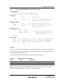
Create Variable-Size Memory Pool ................................................................................ 186
Delete Variable-Size Memory Pool (del_mpl) ............................................................... 190
Get Variable-Size Memory Block (get_mpl, pget_mpl, ipget_mpl, tget_mpl) ............... 191
Release Variable-Size Memory Block (rel_mpl, irel_mpl)............................................. 193
Refer to Variable-Size Memory Pool State (ref_mpl, iref_mpl)..................................... 194
Time Management (System Clock)........................................................................... 195
3.15.1
3.15.2
Set System Clock (set_tim, iset_tim) ............................................................................. 197
Get System Clock (get_tim, iget_tim)............................................................................ 198
Rev.6.00 iii
REJ10B0060-0600
Contents
3.15.3
3.16
3.16.1
3.16.2
3.16.3
3.16.4
3.16.5
3.17
3.22.3
3.22.4
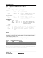
Define CPU Exception Handler (def_exc, idef_exc) ...................................................... 246
Define CPU Exception (TRAPA Instruction Exception) Handler (vdef_trp,
ivdef_trp) ........................................................................................................................ 248
Refer to Configuration Information (ref_cfg, iref_cfg) .................................................. 250
Refer to Version Information (ref_ver, iref_ver)............................................................. 252
Cache Support Function (HI7700/4: for SH-3 and SH3-DSP) ................................. 254
3.23.1
3.23.2
3.23.3
3.23.4
3.24
Define Extended Service Call (def_svc, idef_svc) ......................................................... 243
Call Service Call (cal_svc, ical_svc) .............................................................................. 244
System Configuration Management.......................................................................... 245
3.22.1
3.22.2
3.23
Define Interrupt Handler (def_inh, idef_inh).................................................................. 237
Change Interrupt Mask (chg_ims, ichg_ims).................................................................. 240
Refer to Interrupt Mask (get_ims, iget_ims)................................................................... 241
Service Call Management ......................................................................................... 242
3.21.1
3.21.2
3.22
Rotate Ready Queue (rot_rdq, irot_rdq) ......................................................................... 220
Get Task ID in RUNNING State (get_tid, iget_tid)........................................................ 221
Lock CPU (loc_cpu, iloc_cpu) ....................................................................................... 222
Unlock CPU (unl_cpu, iunl_cpu) ................................................................................... 224
Disable Dispatch (dis_dsp)............................................................................................. 225
Enable Dispatch (ena_dsp) ............................................................................................. 226
Refer to Context (sns_ctx).............................................................................................. 227
Refer to CPU-Locked State (sns_loc)............................................................................. 228
Refer to Dispatch-disabled State (sns_dsp) .................................................................... 229
Refer to Dispatch-Pended State (sns_dpn) ..................................................................... 230
Start Kernel (vsta_knl, ivsta_knl) ................................................................................... 231
System Down (vsys_dwn, ivsys_dwn) ........................................................................... 232
Acquire Trace Information (vget_trc, ivget_trc)............................................................. 233
Acquire Start of Interrupt Handler as Trace Information (ivbgn_int) ............................. 234
Acquire End of Interrupt Handler as Trace Information (ivend_int) .............................. 235
Interrupt Management............................................................................................... 236
3.20.1
3.20.2
3.20.3
3.21
Define Overrun Handler (def_ovr) ................................................................................. 215
Start Overrun Handler (sta_ovr, ista_ovr)....................................................................... 216
Stop Overrun Handler Operation (stp_ovr, istp_ovr)...................................................... 217
Refer to Overrun Handler State (ref_ovr, iref_ovr) ........................................................ 218
System State Management ........................................................................................ 219
3.19.1
3.19.2
3.19.3
3.19.4
3.19.5
3.19.6
3.19.7
3.19.8
3.19.9
3.19.10
3.19.11
3.19.12
3.19.13
3.19.14
3.19.15
3.20
Create Alarm Handler..................................................................................................... 208
Delete Alarm Handler (del_alm) .................................................................................... 210
Start Alarm Handler (sta_alm, ista_alm) ........................................................................ 211
Stop Alarm Handler (stp_alm, istp_alm)........................................................................ 212
Refer to Alarm Handler State (ref_alm, iref_alm).......................................................... 213
Time Management (Overrun Handler)...................................................................... 214
3.18.1
3.18.2
3.18.3
3.18.4
3.19
Create Cyclic Handler .................................................................................................... 201
Delete Cyclic Handler (del_cyc) .................................................................................... 203
Start Cyclic Handler (sta_cyc, ista_cyc)......................................................................... 204
Stop Cyclic Handler (stp_cyc, istp_cyc)......................................................................... 205
Refer to Cyclic Handler State (ref_cyc, iref_cyc)........................................................... 206
Time Management (Alarm Handler)......................................................................... 207
3.17.1
3.17.2
3.17.3
3.17.4
3.17.5
3.18
Supply Time Tick (isig_tim)........................................................................................... 199
Time Management (Cyclic Handler)......................................................................... 200
Initialize Cache (vini_cac, ivini_cac) ............................................................................. 256
Clear Cache (vclr_cac, ivclr_cac)................................................................................... 258
Flush Cache (vfls_cac, ivfls_cac) ................................................................................... 259
Invalidate Cache (vinv_cac, ivinv_cac) .......................................................................... 260
Cache Support Function (HI7750/4: for SH-4) ......................................................... 261
3.24.1
Initialize Cache (vini_cac, ivini_cac) ............................................................................. 263
Rev.6.00 iv
REJ10B0060-0600
Contents
3.24.2
3.24.3
3.24.4
3.25
Cache Support Function (HI7700/4: for SH4AL-DSP without Extended
Function, HI7750/4: for SH-4A without Extended Function) ................................... 267
3.25.1
3.25.2
3.25.3
3.25.4
3.26
Section 4
Application Program Creation ...........................................................289
4.2.6
4.2.7
4.2.8
4.2.9
Normal Interrupt Handler............................................................................................... 307
Direct Interrupt Handler (HI7000/4) .............................................................................. 312
CPU Exception Handler (Including TRAPA Instruction Exception) ........................ 323
Time Event Handlers and Initialization Routine ....................................................... 329
CPU Initialization Routines....................................................................................... 335
4.11.1
4.11.2
4.11.3
4.12
4.13
Reserved Name .............................................................................................................. 297
Reserved TRAP (Only in HI7000/4) .............................................................................. 297
Tasks ......................................................................................................................... 297
Task Exception Processing Routines......................................................................... 302
Extended Service Call Routines ................................................................................ 306
Interrupt Handlers...................................................................................................... 307
4.8.1
4.8.2
4.9
4.10
4.11
SR Register .................................................................................................................... 293
Cache Lock Function (SH-3, SH3-DSP)........................................................................ 294
VBR Register ................................................................................................................. 295
MMU (SH-3, SH3-DSP, SH4AL-DSP, SH-4, SH-4A)................................................... 295
Acceptance of NMI while SR.BL = 1 (SH-3, SH3-DSP, SH4AL-DSP, SH-4,
SH-4A)........................................................................................................................... 295
Nesting the Interrupts (SH-3, SH3-DSP, SH4AL-DSP, SH-4, SH-4A) .......................... 295
32-Bit Address Extension Mode (SH-4A)...................................................................... 295
TBR Register (SH-2A, SH2A-FPU) .............................................................................. 295
Register Banks (SH-2A, SH2A-FPU) ............................................................................ 296
Using SH2A-FPU, SH-4, or SH-4A.......................................................................... 296
System Reserve ......................................................................................................... 297
4.4.1
4.4.2
4.5
4.6
4.7
4.8
Header Files for C/C++ Language ................................................................................. 289
Header Files for Assembly Language ............................................................................ 292
Handling the CPU Resources .................................................................................... 293
4.2.1
4.2.2
4.2.3
4.2.4
4.2.5
4.3
4.4
Initialize Cache (vini_cac, ivini_cac) ............................................................................. 279
Clear Instruction/Operand Cache (vclr_cac, ivclr_cac).................................................. 282
Flush Operand Cache (vfls_cac, ivfls_cac) .................................................................... 284
Invalidate Instruction/Operand Cache (vinv_cac, ivinv_cac) ......................................... 286
Header Files............................................................................................................... 289
4.1.1
4.1.2
4.2
Initialize Cache (vini_cac, ivini_cac) ............................................................................. 269
Clear Instruction/Operand Cache (vclr_cac, ivclr_cac).................................................. 271
Flush Operand Cache (vfls_cac, ivfls_cac) .................................................................... 273
Invalidate Instruction/Operand Cache (vinv_cac, ivinv_cac) ......................................... 275
Cache Support Function (HI7700/4: for SH4AL-DSP with Extended
Function, HI7750/4: for SH-4A with Extended Function) ........................................ 277
3.26.1
3.26.2
3.26.3
3.26.4
4.1
Clear Operand Cache (vclr_cac, ivclr_cac) .................................................................... 264
Flush Operand Cache (vfls_cac, ivfls_cac) .................................................................... 265
Invalidate Operand Cache (vinv_cac, ivinv_cac)............................................................ 266
Creating CPU Initialization Routines in C language ...................................................... 335
Defining CPU Initialization Routines in HI7000/4 ........................................................ 335
Defining CPU Initialization Routines in HI7700/4 and HI7750/4.................................. 336
System Down Routines ............................................................................................. 336
Using the DSP in Programs (for HI7000/4 and HI7700/4 only) ............................... 337
4.13.1
4.13.2
Initializing DSR ............................................................................................................. 337
Using DSP in Handlers .................................................................................................. 338
Rev.6.00 v
REJ10B0060-0600
Contents
Section 5
5.1
Configuration .......................................................................................341
Read First .................................................................................................................. 341
5.1.1
5.2
5.2.1
5.2.2
5.2.3
5.2.4
5.2.5
5.3
5.4
5.8
5.9
Adding Files to a Project ................................................................................................ 380
Defining Endian (HI7700/4 and HI7750/4) .................................................................... 380
Setting Optimized Linkage Editor Options..................................................................... 381
Executing a Build ........................................................................................................... 384
Build at Separate Linkage: Kernel Environment Side (cfg)...................................... 385
5.14.1
5.14.2
5.14.3
5.14.4
5.15
Adding Files to a Project ................................................................................................ 375
Defining Endian.............................................................................................................. 375
Setting Optimized Linkage Editor Options..................................................................... 376
Executing a Build ........................................................................................................... 379
Build for Separate Linkage: Kernel Side (def).......................................................... 380
5.13.1
5.13.2
5.13.3
5.13.4
5.14
CPU Options for the Compiler and Assembler............................................................... 373
GBR Option of Compiler (Compiler Package V.7.1 or Later)........................................ 373
PACK Option and #pragma pack of Compiler (Compiler Package V.8 or Later) ........... 374
Include Directory for Compiler and Assembler.............................................................. 374
When SH2A-FPU or SH-4 or SH-4A is Used ................................................................ 374
TBR Option of Compiler (Compiler Package V.9 or Later) ........................................... 374
Build for Whole Linkage (mix)................................................................................. 375
5.12.1
5.12.2
5.12.3
5.12.4
5.13
HI7000/4......................................................................................................................... 367
HI7700/4......................................................................................................................... 367
HI7750/4......................................................................................................................... 370
Section Configuration ............................................................................................... 371
Settings Common to All Projects .............................................................................. 373
5.11.1
5.11.2
5.11.3
5.11.4
5.11.5
5.11.6
5.12
Overview ........................................................................................................................ 350
Configurator Construction.............................................................................................. 351
File Operation................................................................................................................. 352
Configuration Files......................................................................................................... 352
Separate Linkage ............................................................................................................ 354
Configurator Settings...................................................................................................... 355
When Optimized Timer Driver is Used (HI7700/4) ................................................. 364
When DSP Standby Control Function is Used (HI7700/4)....................................... 364
When Cache Support Function is Used on SH4AL-DSP (HI7700/4) or SH4A (HI7750/4)........................................................................................................... 364
HEW Workspace and Projects .................................................................................. 365
Kernel Libraries ........................................................................................................ 367
5.9.1
5.9.2
5.9.3
5.10
5.11
hihead Folder.................................................................................................................. 344
hisys Folder .................................................................................................................... 344
hilib Folder ..................................................................................................................... 344
knl Folder ....................................................................................................................... 344
samples\shnnnn Folder ................................................................................................... 344
Operating Procedure ................................................................................................. 349
Configurator .............................................................................................................. 350
5.4.1
5.4.2
5.4.3
5.4.4
5.4.5
5.4.6
5.5
5.6
5.7
Whole Linkage and Separate Linkage ............................................................................ 341
Folder Structure ........................................................................................................ 344
Adding Files to a Project ................................................................................................ 385
Defining Endian (HI7700/4 and HI7750/4) .................................................................... 385
Setting Optimized Linkage Editor Options..................................................................... 386
Executing a Build ........................................................................................................... 388
Application Load Module Creation .......................................................................... 388
Rev.6.00 vi
REJ10B0060-0600
Contents
Appendix A
Service Call List ...................................................................................389
Appendix B
Error List..............................................................................................401
B.1
B.2
B.3
Service Call Error Code List ..................................................................................... 401
Information during System Down ............................................................................. 402
Error during Compiling ............................................................................................. 403
B.3.1
B.3.2
B.3.3
Error when Files are for a Different HI7000/4 Series..................................................... 403
Errors to Do with the Optimized Timer Driver (HI7700/4)............................................ 403
Errors to Do with the DSP-Standby Control Function (HI7700/4) ................................ 404
Appendix C
Calculation of Work Area Size...........................................................405
C.1
C.2
C.3
C.4
C.5
C.6
Work Areas ............................................................................................................... 405
Stack Types ............................................................................................................... 406
Stack Size Calculation Procedure.............................................................................. 407
Calculation of Stack Size for Each Function............................................................. 408
Stack Size Considering Programming Nesting.......................................................... 409
Task Stacks................................................................................................................ 411
C.6.1
C.6.2
C.7
Interrupt Handler Stacks............................................................................................ 413
C.7.1
C.7.2
C.8
C.9
C.10
Stack Size Used by an Interrupt Handler........................................................................ 413
Stack Area Allocation .................................................................................................... 414
Stack Size Used by a Time Event Handler and Timer Interrupt Routine .................. 415
Initialization Routine Stacks...................................................................................... 417
Timer Initialization Routine Stack ............................................................................ 418
Appendix D
D.1
D.2
Stack Size Used by Each Task........................................................................................ 411
Stack Area Acquisition................................................................................................... 412
Timer Driver ........................................................................................419
Overview ................................................................................................................... 419
Standard Timer Driver............................................................................................... 419
D.2.1
D.2.2
Installing the Time Management Function..................................................................... 419
Sample Timer Driver...................................................................................................... 421
Appendix E
Optimized Timer Driver (HI7700/4) ..................................................423
E.1
E.2
E.3
E.4
E.5
E.6
Overview ................................................................................................................... 423
Operation................................................................................................................... 423
Applicable MCUs...................................................................................................... 425
Hardware Initialization.............................................................................................. 425
Differences with the Standard Timer Driver ............................................................. 425
Ways to Include Optimized Timer Driver ................................................................. 426
E.6.1
E.6.2
E.6.3
E.6.4
E.7
Kernel Libraries to be Used....................................................................................... 428
Appendix F
F.1
F.2
F.3
Overview ........................................................................................................................ 426
Creating the kernel_def_opttmr_set.h Definition File .................................................... 426
Notes on the Configurator .............................................................................................. 427
Modifying kernel_sys.h.................................................................................................. 428
DSP Standby Control (HI7700/4).......................................................429
Overview ................................................................................................................... 429
Applicable MCUs...................................................................................................... 431
Module-Standby State when Initiating Programs...................................................... 431
Rev.6.00 vii
REJ10B0060-0600
Contents
F.4
F.5
Service Call for Changing the TA_COP0 Attribute (vchg_cop)............................... 432
Ways to Include DSP Standby Control Function...................................................... 433
F.5.1
F.5.2
F.5.3
F.6
F.7
Kernel Libraries to be Used ...................................................................................... 435
Notes ......................................................................................................................... 435
Appendix G
G.1
Overview ........................................................................................................................ 438
SH-4, SH-4A .................................................................................................................. 439
SH2A-FPU ..................................................................................................................... 441
Extended Service Call Routine ................................................................................. 441
G.3.1
G.3.2
G.3.3
G.4
Initialization of FPSCR .................................................................................................. 437
Attributes TA_COP1 and TA_COP2 .............................................................................. 438
Non-Task Context (Normal Interrupt Handler, Direct Interrupt Handler, CPU
Exception Handler, Time Event Handler, Initialization Routine) ............................. 438
G.2.1
G.2.2
G.2.3
G.3
Notes on FPU of SH2A-FPU, SH-4, SH4A ........................................437
Task and Task Exception Processing Routine .......................................................... 437
G.1.1
G.1.2
G.2
Overview ........................................................................................................................ 433
Creating the kernel_def_dspstby_set.h Definition File................................................... 433
Modifying kernel_sys.h.................................................................................................. 435
Compiler Options ........................................................................................................... 441
Called from Task Context............................................................................................... 442
Called from Non-Task Context....................................................................................... 442
Information for Reference......................................................................................... 443
G.4.1
G.4.2
G.4.3
States on the Initiation of Tasks and Handlers................................................................ 443
FPSCR Structure ............................................................................................................ 444
Handling by the Compiler .............................................................................................. 445
Appendix H
New Functions of HI7000/4 V.2 ..........................................................447
H.1
Support of SH-2A and SH2A-FPU ........................................................................... 447
H.1.1
H.1.2
H.1.3
H.2
H.3
H.4
H.5
H.6
H.7
H.8
H.9
H.10
H.11
H.12
H.13
H.14
Specifying Address of Task Stack, Fixed-Size Memory Pool, and VariableSize Memory Pool (V.2.00 Release 00) .................................................................... 448
Management Method of Fixed-Size Memory Pool (V.2.00 Release 00) .................. 449
Direct Interrupt Handler (V.2.00 Release 00 and V.2.02 Release 00) ...................... 450
Macros for Calculating Size (V.2.00 Release 00) ..................................................... 450
Extension of Maximum Vector Number (V.2.00 Release 00) .................................. 450
ID Name (V.2.00 Release 00) ................................................................................... 451
Support of Little Endian in SH-2 (V.2.00 Release 01).............................................. 451
Improvement of Variable-Size Memory Pool (V.2.01 Release 00) ......................... 451
Initial Value of DSR (V.2.01 Release 00)................................................................. 452
Initial Value of SR in Task Exception Processing Routine (V.2.01 Release
00) ............................................................................................................................. 452
Handling of Vector Numbers 16 to 31 (V.2.01 Release 00) ..................................... 452
Lifting of Restriction concerning Structure Alignment (V.2.01 Release 00)............ 453
[Open the file used last time] Command for the Configurator (V.2.02 Release
00) ............................................................................................................................. 453
Appendix I
I.1
FPU (SH2A-FPU) (V.2.00 Release 00) .......................................................................... 447
TBR Register (V.2.00 Release 00).................................................................................. 447
Register Banks (V.2.00 Release 00, V.2.01 Release 00 and V.2.02 Release 00) ............. 448
New Functions of HI7700/4 V.2 ..........................................................455
Support of SH4AL-DSP (with Extended Function) (V.2.01 Release 00) ................. 455
Rev.6.00 viii
REJ10B0060-0600
Contents
I.2
I.3
I.4
I.5
I.6
I.7
I.8
I.9
I.10
I.11
I.12
Specifying Address of Task Stack, Fixed-Size Memory Pool, and VariableSize Memory Pool (V.2.01 Release 00) .................................................................... 455
Management Method of Fixed-Size Memory Pool (V.2.01 Release 00) .................. 455
Improvement of Variable-Size Memory Pool (V.2.01 Release 00)........................... 457
Macros for Calculating Size (V.2.01 Release 00) ..................................................... 458
Initial Value of DSR (V.2.01 Release 00) ................................................................. 458
Initial Value of SR in Task Exception Processing Routine (V.2.01 Release
00) ............................................................................................................................. 459
Extension of Maximum Exception Code (CFG_MAXVCTNO) (V.2.01
Release 00) ................................................................................................................ 459
Handling of TRAPA #16 to #31 (V.2.01 Release 00) ............................................... 459
Release of Restriction concerning Structure Alignment (V.2.01 Release 00).......... 459
ID Name (V.2.01 Release 00) ................................................................................... 460
[Open the file used last time] Command for the Configurator (V.2.02 Release
00) ............................................................................................................................. 460
Appendix J
J.1
J.2
J.3
J.4
J.5
J.6
J.7
J.8
J.9
J.10
J.11
New Functions of HI7750/4 V.2..........................................................461
Support of SH-4A (with Extended Function) (V.2.01 Release 00) ........................... 461
Specifying Address of Task Stack, Fixed-Size Memory Pool, and VariableSize Memory Pool (V.2.01 Release 00) .................................................................... 461
Management Method of Fixed-Size Memory Pool (V.2.01 Release 00) .................. 461
Improvement of Variable-Size Memory Pool (V.2.01 Release 00)........................... 463
Macros for Calculating Size (V.2.01 Release 00) ..................................................... 464
Initial Value of SR in Task Exception Processing Routine (V.2.01 Release
00 or Later)................................................................................................................ 464
Extension of Maximum Exception Code (CFG_MAXVCTNO) (V.2.01
Release 00) ................................................................................................................ 464
Handling of TRAPA #16 to #31 (V.2.01 Release 00) ............................................... 465
Release of Restriction concerning Structure Alignment (V.2.01 Release 00)........... 465
ID Name (V.2.01 Release 00) ................................................................................... 465
[Open the file used last time] Command for the Configurator (V.2.02 Release
00) ............................................................................................................................. 465
Rev.6.00 ix
REJ10B0060-0600
Section 1 Introduction
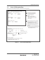
1.1
Overview
Operating systems (OSs) for system development have grown with the ever-increasing use of
microcomputer systems in a wide variety of fields. In particular, realtime OSs have gained wide
acceptance for use in industrial measurement and control systems.
1.2
Features
The HI7000/4 series kernel is based on the µITRON4.0 specifications. Features of the kernel are
outlined below.
• Comprehensive functions for realtime and multitasking processing
• Priority-based task scheduling
• Task management, including the creation, deletion, initiation, and termination of tasks
• Task synchronization, including suspension and resumption of tasks, and task event flags
• Task exception processing functions, including the definition, request, enabling, and
disabling of task exception processing
• Extended inter-task synchronization and communication using semaphores, event flags, data
queues, and mailboxes
• Inter-task synchronization and communication using mutexes and message buffers
• Memory pool management, including control over the allocation and return of memory
blocks
• Control over timing, such as setting and referring to the system clock, and controlling the
cyclic handler, alarm handler, and overrun handler
• System management
• Interrupt management
• Service call management, including the definition and issue
• System configuration management, including the definition of CPU exception handlers
• Support of DSP and FPU (note that the HI7000/4 does not support the FPU in the SH-2E
processor)
• Cache support function (only for HI7700/4 and HI7750/4)
• Optimized timer driver and DSP standby control function for low-power consumption (only
for HI7700/4)
• A compact kernel with optional selection of kernel functions
The size of the kernel program and size of its work area are reduced to minimize the ROM
and RAM size required by the user system. The kernel optimized for the user system can be
configured by selecting the kernel functions to be used by the user system.
• Sample programs
The following sample source programs are provided. By modifying the programs as
required, the user system can easily be created and customized for the user.
Rev.6.00 1
REJ10B0060-0600
Section1 Introduction
⎯ System down routine
⎯ Timer driver for on-chip timers of SuperH™ microcomputer series
⎯ CPU initialization routine
⎯ Section initialization and definition file
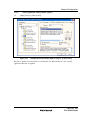
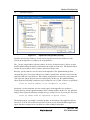
• Configurator
The configurator is supported to ease kernel configuration.
• Debugging extension (option)
The debugging extension which adds a multitasking debugging function to HEW3 or later
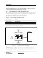
versions of HEW is prepared. The debugging extension supports the following functions.
• Refer to the status of objects, such as a task
• Operate to objects, such as starting task, or set event flag
• Display service call history
The debugging extension can be downloaded free of charge from our homepage.
Rev.6.00 2
REJ10B0060-0600
Section1 Introduction
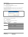
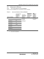
1.3
Operating Environment
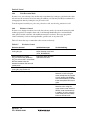
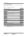
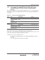
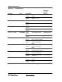
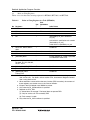
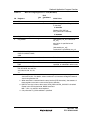
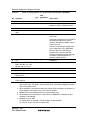
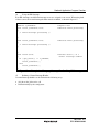
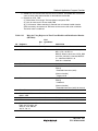
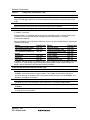
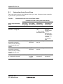
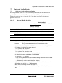
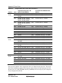
The operating environment is shown in table 1.1.
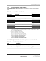
Table 1.1
Operating Environment
Product
Name
Files Included
Operating Environment
HI7000/4
Kernel
All SuperH™ microcomputers incorporating SH-1, SH-2,
SH2-DSP, SH-2A, or SH2A-FPU
Sample program
Some SuperH™ microcomputers incorporating SH-1, SH-2,
SH2-DSP, SH-2A, or SH2A-FPU
Sample HEW
workspace and
project
HEW version 1.2 or later (SuperH™ RISC engine C/C++
compiler package version 6.0C or later)
Configurator
Windows® 98, Windows® Millennium Edition (Windows®
Me), WindowsNT® 4.0, Windows® 2000, and Windows® XP
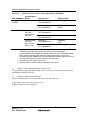
Kernel
All SuperH™ microcomputers incorporating SH-3, SH3DSP, or SH4AL-DSP
Sample program
Some SuperH™ microcomputers incorporating SH-3, SH3DSP, or SH4AL-DSP
Sample HEW
workspace and
project
HEW version 1.2 or later (SuperH™ RISC engine C/C++
compiler package version 6.0C or later)
Configurator
Windows® 98, Windows® Millennium Edition (Windows®
Me), WindowsNT® 4.0, Windows® 2000, and Windows® XP
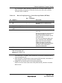
HI7700/4
HI7750/4
1.4
Kernel
All SuperH™ microcomputers incorporating SH-4 or SH-4A
Sample program
Some SuperH™ microcomputers incorporating SH-4 or SH4A
Sample HEW
workspace and
project
HEW version 1.2 or later (SuperH™ RISC engine C/C++
compiler package version 6.0C or later)
Configurator
Windows® 98, Windows® Millennium Edition (Windows®
Me), WindowsNT® 4.0, Windows® 2000, and Windows® XP
Installation
Refer to release notes attached to the product.
Rev.6.00 3
REJ10B0060-0600
Section1 Introduction
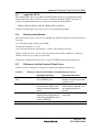
1.5
Target Product of This Manual
•
HI7000/4: V.2.02 Release 00 or later
•
HI7700/4: V.2.02 Release 00 or later
•
HI7750/4: V.2.02 Release 00 or later
Rev.6.00 4
REJ10B0060-0600
Section 2 Kernel
2.1
Overview
The kernel, which is the nucleus of the operating system, enables realtime multitasking. It has
three major roles.
• Response to events
Recognizes events generated asynchronously, and immediately executes a task to process the
event.
• Task scheduling
Schedules task execution on a priority basis.
• Service call execution
Accepts various requests for processing (service calls) from tasks and performs the
appropriate processing.
2.2
Functions
An application program can issue service calls to almost any kernel function.
Task Management: When a task is executed, the CPU is allocated to the task. The kernel
controls the order of CPU allocation, and of the start and end of tasks. Multiple tasks can share
one stack by using the shared-stack function.
Task Synchronization Management: Performs basic synchronous processing for tasks, such as
suspension of task execution, resumption, and task event flag processing.
Synchronization and Communication Management: Uses event flags, semaphores, data
queues, and mailboxes for inter-task synchronization and communication.
Extended Synchronization and Communication Management: Uses mutex and message
buffers for inter-task synchronization and communication.
Memory Pool Management: Manages unused memory in the user system as a memory pool. A
task dynamically acquires blocks from or returns them to the memory pool. The size of the
memory pool can be fixed or variable.
Time Management: Manages time-related information for the system and monitors task
execution times for control purposes.
System State Management: Performs system state management functions, such as modifying
or referencing the context or system states.
Interrupt Management: Initiates the appropriate interrupt handlers in response to external
interrupts. The interrupt handler performs appropriate interrupt processing, and notifies tasks of
interrupts.
Service Call Management: Defines or calls an extended service call.
Rev.6.00 5
REJ10B0060-0600
Section2 Kernel
System Configuration Management: Performs system configuration management functions,
such as defining the CPU exception handlers and reading the kernel version number.
DSP/FPU Support: Supports the DSP and FPU in its multitasking environment. Each task can
use special registers to execute DSP/FPU instructions.
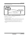
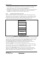
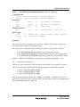
2.3
Processing Units and Precedence
An application program is executed in the following processing units.
Task: A task is a unit controlled by multitasking.
Task Exception Processing Routine: A task exception processing routine is executed when a
task exception processing is requested by a task in the ras_tex service call.
Interrupt Handler: An interrupt handler is executed when an interrupt occurs.
CPU Exception Handler: A CPU exception handler is executed when a CPU exception occurs.
Time Event Handler (Cyclic Handler, Alarm Handler, and Overrun Handler):
A time event handler is executed when a specified cycle or time has been reached.
Extended Service Call: An extended service call is used to call a module that is not linked.
When this extended service call is issued, the corresponding extended service call routine is
called.
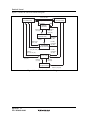
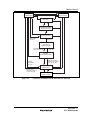
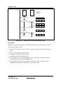
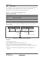
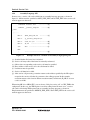
Each processing unit is processed with the following precedence.
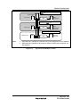
(1) Interrupt handlers, time event handlers and CPU exception handlers
(2) Dispatcher (part of kernel processing)
(3) Tasks
The dispatcher is a kernel processing that switches a task to be executed.
The precedence of an interrupt handler becomes higher when an interrupt level is higher.
The precedence of a time event handler is the same as a timer interrupt level
(CFG_TIMINTLVL).
The precedence of a CPU exception handler is higher than that of the processing where the CPU
exception occurred and of the dispatcher. The precedence of a CPU exception handler is also
lower than that of other processings which have the higher precedence than those where the
CPU exception occurred.
The precedence between tasks depends on the priority of these tasks.
The precedence of an extended service call routine is higher than that of the processing where
the extended service call was called. The precedence of an extended service call routine is also
lower than that of other processings which have the higher precedence than those where the
extended service call was called.
Rev.6.00 6
REJ10B0060-0600
Section2 Kernel
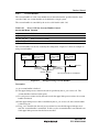
The precedence of a task's exception processing routine is higher than that of the task and lower
than that of other higher-level tasks.
When the following service calls are called, the precedence which does not apply above can be
temporarily generated:
(a) When dis_dsp is called, the precedence will be the middle of (1) and (2) above. The state
returns to former state by calling dis_dsp.
(b) When loc_cpu or iloc_cpu is called, the precedence will be the same as that of the
interrupt handler of which interrupt level is the same as CFG_KNLMSKLVL. The state
returns to former state by calling unl_cpu or iunl_cpu.
(c) While the interrupt mask level is changed to other than 0 by chg_ims, the precedence is
the same as an interrupt handler which has the same level.
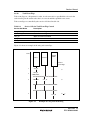
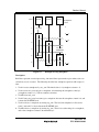
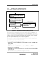
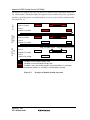
2.4
System State
The system state is classified into the following orthogonal states.
• Task context state/non-task context state
• Dispatch-disabled state/dispatch-enabled state
• CPU-locked state/CPU-unlocked state
The system operations and available service calls are determined based on the above system
states.
Rev.6.00 7
REJ10B0060-0600
Section2 Kernel
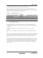
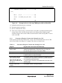
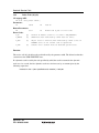
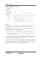
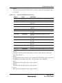
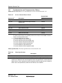
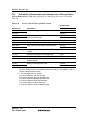
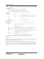
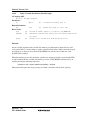
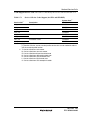
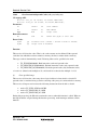
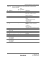
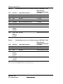
2.4.1
Task Context State and Non-Task Context State
The system is executed in either task context state or non-task context state. The difference
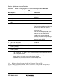
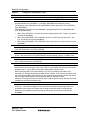
between task and non-task context states is described in table 2.1.
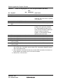
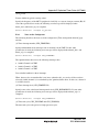
Table 2.1
Task Context State and Non-Task Context State
Item
Task Context State
Non-Task Context State
Available service calls
Service calls that can be called
from the task context
Service calls that can be called from
the task context
Task scheduling
Refer to sections 2.4.2 and 2.4.3 Does not occur
The following processing is executed in non-task context.
• Interrupt handler
• CPU exception handler
• Time event handler (cyclic handler, alarm handler, and overrun handler)
• A part where the interrupt mask is changed to a value other than 0 by the chg_ims service
call
Note that extended service calls initiated in the above processing state are also executed in nontask context.
2.4.2
Dispatch-Disabled State/Dispatch-Enabled State
The system is placed in either dispatch-disabled state or dispatch-enabled state. In dispatchdisabled state, task scheduling is not allowed and service calls that place a task in the WAITING
state cannot be used.
Issuing the dis_dsp service call during task execution changes the system state to dispatchdisabled state. Issuing the ena_dsp service call will return the system state to the dispatchenabled state. Issuing the sns_dsp service call will check whether the system state is in dispatchdisabled state or not.
Rev.6.00 8
REJ10B0060-0600
Section2 Kernel
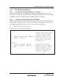
2.4.3
CPU-Locked State/CPU-Unlocked State
The system is placed in either CPU-locked state or CPU-Unlocked state. In CPU-locked state,
interrupts and task scheduling are not allowed. Note, however, that interrupts with interrupt
mask levels higher than that specified in the kernel mask level (CFG_KNLMSKLVL) in
configuration are allowed. In this state, service calls that place a task in the WAITING state
cannot be used.
Issuing the loc_cpu or iloc_cpu service call during task execution changes the system state to
CPU-locked state. Issuing an unl_cpu or iunl_cpu will return the system state to the CPUunlocked state. In addition, issuing the sns_loc service call will check whether the system state is
in CPU-locked state or not.
In the CPU-locked state, service calls than can be issued are restricted as described in 3.2.5,
System State and Service Calls.
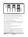
2.5
Objects
Objects such as tasks and semaphores are manipulated by service calls. Objects are identified by
ID numbers or object numbers. The maximum number can be specified for almost all objects in
configuration.
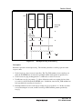
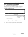
2.6
Tasks
In a realtime multitasking system, the user prepares an application program in terms of a set of
tasks that can be processed independently and in parallel.
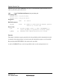
A task communicates with other tasks by using service calls. Such service calls can be used to
have the kernel process events that are asynchronously generated by external devices or by the
MCU.
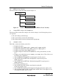
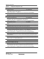
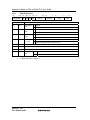
Tables 2.2 and 2.3 list the service calls that operate tasks.
Rev.6.00 9
REJ10B0060-0600
Section2 Kernel
Table 2.2
Task-Management Service Calls
Service Call
Description
cre_tsk, icre_tsk
Creates task (using dynamic stack)
vscr_tsk, ivscr_tsk
Creates task (using static stack)
acre_tsk, iacre_tsk
Creates task (automatically assigns task ID)
del_tsk
Deletes task
act_tsk, iact_tsk
Starts task
can_act, ican_act
Cancels start task request
sta_tsk, ista_tsk
Starts task (specifies start task code)
ext_tsk;
Exits current task
exd_tsk
Exits current task and deletes it
ter_tsk
Forcibly terminates a task
chg_pri, ichg_pri
Changes task priority
get_pri, iget_pri
Refers to task priority
ref_tsk, iref_tsk
Refers to task state
ref_tst, iref_tst
Refers to task state (simple version)
vchg_tmd
Changes task execution mode
Table 2.3
Task Synchronization Service Calls
Service Call
Description
slp_tsk
Sleep task
tslp_tsk
Sleep task with timeout
wup_tsk, iwup_tsk
Wakeup task
can_wup, ican_wup
Cancel wakeup task
rel_wai, irel_wai
Release WAITING state forcibly
sus_tsk, isus_tsk
Suspend task
rsm_tsk, irsm_tsk
Resume task
frsm_tsk, ifrsm_tsk
Resume task forcibly
dly_tsk
Delay task
Rev.6.00 10
REJ10B0060-0600
Section2 Kernel
2.6.1
Task State and Transition
A task can be in any of the following seven states in the user system.
NON-EXISTENT State: A task has not been registered in the kernel and has been in a virtual
state.
DORMANT State: A task has been registered in the kernel but has not yet been initiated, or has
already been terminated.
READY (executable) State: An executable task is in the queue is waiting for CPU resource
allocation because another higher priority task is currently running.
RUNNING State: The task is currently running. The kernel puts the READY task with the
highest priority in the RUNNING state.
WAITING State: A task issues a service call such as tslp_tsk to put itself to sleep when it can
no longer continue execution. The task is released (awakened) from the WAITING (sleep) state
when the service call wup_tsk is issued, and it then makes the transition to the READY state.
SUSPENDED State: A task has been suspended by another task by sus_tsk.
WAITING-SUSPENDED State: This state is a combination of the WAITING state and
SUSPENDED state.
Rev.6.00 11
REJ10B0060-0600
Section2 Kernel
Figure 2.1 shows the task-state transition diagram.
CPU allocation
READY
(executable state)
RUNNING
(execution state)
Waiting for CPU allocation
Wait release
Wait
WAITING
(wait state)
Suspension
(sus_tsk)
Resumption
(rsm_tsk,
frsm_tsk)
WAITING-SUSPENDED
(double-wait state)
Wait
release
Suspension
(sus_tsk)
SUSPENDED
(forcible-wait state)r
Resumption
(rsm_tsk, frsm_tsk)
Forcible
termination
(ter_tsk)
Forcible
termination
(ter_tsk)
Forcible
termination
(ter_tsk)
Initiation
(act_tsk, sta_tsk)
DORMANT
(inactive state)
Forcible termination
(ter_tsk)
Exit (ext_tsk)
Creation
(cre_tsk)
Deletion
(del_tsk)
NON-EXISTENT
(unregistered state)
Figure 2.1
Rev.6.00 12
REJ10B0060-0600
Exit and
deletion (exd_tsk)
Task State Transition Diagram
Section2 Kernel
2.6.2
Task Creation
Task creation means that a NON-EXISTENT task becomes DORMANT. The method of
creating a task differs depending on the stack type used by the task to be created. For details,
refer to section 0,
Task Stack. The methods of creating a task are shown in table 2.4.
Table 2.4
Task Creating Methods
Stack Type Used by Created Task
Task Creating Method
Static Stack
Stack Allocated by
Dynamic Stack Application
cre_tsk, acre_tsk service calls
vscr_tsk service call
9
Configurator
9
9
9
9
9
2.6.3
Task Initiation
A task is initiated when it moves from the DORMANT state to become READY. A task can be
initiated by one of two methods:
• By issuing the act_tsk or sta_tsk service calls for the target task
• By specifying TA_ACT as a task attribute when a task is created
The kernel performs the following processing at task initiation.
• Initialize the task base priority and current priority
• Clear the number of task wake-up requests
• Clear the number of nestings of task suspension requests
• Clear the pended task exception sources
• Set task exception processing to the disabled state
• Set the task event flag to 0
The following parameter is passed to the task.
(1) When TA_ACT attribute is specified at task creation and when the task is started by act_tsk
service call
The extended information (exinf) which is specified at task creation is passed to the task.
(2) When the task is started by sta_tsk service call
The task start code (stacd) which is specified by sta_tsk service call is passed to the task.
Rev.6.00 13
REJ10B0060-0600
Section2 Kernel
2.6.4
Task Scheduling
Scheduling: For each task, a task priority is assigned to determine the priority of processing. A
smaller value indicates a higher priority level and level 1 is the highest priority.
The kernel selects the highest-priority task from the READY tasks and puts it in the RUNNING
state.
The same priority can be assigned for multiple tasks. When there are multiple READY tasks
with the highest priority, the kernel selects the first task that became READY and puts it in the
RUNNING state. To implement this behavior, the kernel has ready queues, which are READY
task queues waiting for execution.
While execution is in a non-task context, no task is executed until the non-task context
processing is completed.
Round-Robin Scheduling: The kernel also supports round-robin scheduling, where the CPU
allocates equal time to tasks with a given priority by rotating the ready queue at specific
intervals. The round-robin scheduling can be achieved by issuing the rot_rdq service call that
manipulates the ready queues.
• Round-Robin Scheduling with rot_rdq Service call
By issuing rot_rdq at specific cycles, execution can be switched at specific intervals to a task
that has the same priority as the executing task.
Limitations to Scheduling: When the system enters the dispatch-disabled state by the dis_dsp
service call, task scheduling is disabled. Task scheduling is enabled when the system enters the
dispatch-enabled state by the ena_dsp service call.
When the system enters the CPU-locked state by the loc_cpu service call, both task scheduling
and all interrupts other than kernel management interrupts are disabled. Task scheduling and
interrupts are enabled when the system enters the CPU-unlocked state by the unl_cpu service
call.
Rev.6.00 14
REJ10B0060-0600
Section2 Kernel
2.6.5
Task Termination and Deletion
Task termination means that a task is finished and can enter the DORMANT or NONEXISTENT state.
• ext_tsk is issued
• exd_tsk is issued
• ter_tsk is issued to the target task
When a task is terminated and then re-initiated, or when the number of initiation request queues
specified in the act_tsk service call is other than 0, the task starts from the initial state.
When a task will no longer be used or when re-assigning the task ID to another task or, the
exd_tsk service call is issued and the task is made NON-EXISTENT. The ID can now be
assigned to another task. A task must release its resources before execution can be completed.
Note that the mutex is unlocked when a task is terminated and deleted.
The kernel performs the following processing when a task is terminated:
• Unlock the mutex that is locked by the current task
• Clear the upper limit processor time
The kernel performs the following processing when a task is deleted:
• Release the task stack area
2.6.6
Task Stack
There are three methods of allocating stacks.
Static Stack: The static stack is defined for each task by the configurator when the system is
configured. A shared stack function, which allows more than one task to use a single stack, is
available for tasks that use the static stack.
Dynamic Stack: When a task is created, the kernel assigns a stack area to the task . The stack is
allocated in the dynamic stack area (CFG_TSKSTKSZ). A shared stack function is not available
for tasks that use a dynamic stack.
Stack Allocated by Application: The application allocates a stack area and specifies the
address at task creation. A shared stack function is not available for tasks that use this type of
stack.
Rev.6.00 15
REJ10B0060-0600
Section2 Kernel
The configurator specifies the maximum task ID (CFG_STSTKID), which represents the
maximum ID of a task using the static stack, and the maximum task ID (CFG_MAXTSKID) in
the system. Tasks with task IDs between 1 and CFG_STSTKID use the static stack, while tasks
with task IDs between CFG_STSTKID + 1 and CFG_MAXTSKID use the dynamic stack or
stack allocated by application. If CFG_STSTKID is specified as 0, no static stack is used. If
CFG_STSTKID and CFG_MAXTSKID are specified as the same value, all tasks use the static
stack.
2.6.7
Shared Stack Function
More than one task can share one static stack. This reduces the total stack area. The shared stack
function is not defined in the µITRON4.0 specification.
Shared stack and static stack assignment is defined by the configurator. However, only one task
in a task group that shares a stack can be executed at a time. When multiple tasks are initiated
and share a stack, the task that was initiated first uses the stack first. The remaining tasks enter
the shared-stack wait state. Tasks in the shared-stack wait state are managed as a first-in firstout (FIFO) queue, regardless of their priority. Tasks are sent to the shared-stack wait queue in
the order in which they were initiated.
A shared stack is released from the task when the task becomes DORMANT. When tasks are
waiting for the shared stack, the task at the head of the wait queue will use the stack, and enters
the READY state.
Figure 2.2 shows the task-state transitions for the shared stack function.
Rev.6.00 16
REJ10B0060-0600
Section2 Kernel
READY
(executable state)
RUNNING
(execution state)
WAITING
(wait state)
WAITING-SUSPENDED
(double-wait state)
SUSPENDED
(forcible-wait state)
Shared stack
allocation
Shared stack
allocation
WAITING-SUSPENDED
(shared stack
double-wait state)
Resumption
(rsm_tsk, frsm_tsk)
Suspension
(sus_tsk)
WAITING
(shared stack wait state)
Forcible
termination
(ter_tsk)
When the shared
stack is monopolized
(act_tsk, sta_tsk)
DORMANT
(inactive state)
Shared stack is
released or unused
(act_tsk, sta_tsk)
NON-EXISTENT
(unregistered state)
Figure 2.2
Task-State Transitions for the Shared Stack Function
Rev.6.00 17
REJ10B0060-0600
Section2 Kernel
2.6.8
Task Execution Mode
In some cases, one task may force another task to terminate (by issuing ter_tsk) before the other
task releases the resources it has been using. In addition, one task may forcibly be terminated at
an inappropriate time by issuing the sus_tsk service call.
To mask requests issued by ter_tsk or sus_tsk service calls, use the vchg_tmd service call.
2.6.9
Exclusive Control
In some cases, during execution of one task, the task may need to be executed exclusively with
another program. For example, when task A and interrupt handler B refer to and modify the
same global variable, reference and modification must be exclusive. The target program to
control exclusivity can be an interrupt handler, specific task, or any other task.
Table 2.5 shows the way to ensure that tasks execute exclusively.
Table 2.5
Exclusive Control
Exclusive Control
Inhibited Interrupts
Task Scheduling
Enter the CPU-locked state by
issuing loc_cpu
Equal to or lower than the
kernel interrupt mask level
(CFG_KNLMSKLVL)
None
Mask interrupts by issuing
chg_ims service call (When the
chg_ims service call is issued from
the task context state, the
execution becomes the non-task
context state
Equal to or lower than the
specified mask level
None
Enter disabled-dispatch state by
issuing dis_dsp service call
None
None
Exclusive control by semaphore
None
The kernel schedules tasks;
however, in tasks using the
same semaphore, the number
of tasks entering the READY
state simultaneously is limited
to the semaphore initial count
value.
Exclusive control by mutex
None
The kernel schedules tasks;
however, tasks using the
same mutex cannot enter the
READY state simultaneously.
In addition, in tasks using the
same mutex, the task priority
inversion will not occur.
Rev.6.00 18
REJ10B0060-0600
Section2 Kernel
2.6.10
Task Event Flags
Task event flags are a bit patterns for tasks. A task can wait for a specified bit to be set in the
task event flag for the current task; that is, it can wait until the specified event occurs.
Task event flags are controlled by the service calls listed in table 2.6.
Table 2.6
Service Calls for Task Event Flag Control
Service Call Name
Description
vset_tfl, ivset_tfl
Sets task event flag
_
vclr tfl, ivclr_tfl
Clears the event flag
vwai_tfl
Waits for event occurrence
vpol_tfl
Polls for event occurrence
vtwai_tfl
Waits for event to occur, with timeout
Figure 2.3 shows an example of the using task event flags.
Time
Task A
Task B
Interrupt
handler
C
Task A
event flags
1
vclr_tfl
2
vwai_tfl
<WAITING>
3
<READY>
0
4
Figure 2.3
vset_tfl
0
ivset_tfl
0
7
Example of Using Task Event Flag
Rev.6.00 19
REJ10B0060-0600
Section2 Kernel
Description:
The bold lines indicate executed processing, and the following describes the task event flag
operation with respect to time.
1. Task A issues vclr_tfl to clear all bits in its task event flag.
2. Task A issues vwai_tfl (waiting pattern = H'ffffffff) to wait for an event.
3. Task B issues vset_tfl (set pattern = 1) to task A. Since this set pattern is included in the
waiting pattern specified in task A, the WAITING state of task A is cancelled and the task A
event flags are cleared to 0.
4. Interrupt handler C issues ivset_tfl (set pattern = 7) to set event flags of the task A. In this
case, however, task A does not wait for an event, therefore the task event flags are logically
ORed with a pattern specified by vset_tfl.
2.7
Task Exception Processing
Task exception processing is performed when an exception occurs during task execution. Task
exception processing is performed asynchronously with task processing and is similar to the
function generally called "signal".
Task exception processing is controlled by the service calls listed in table 2.7.
Table 2.7
Service Calls for Task Exception Processing
Service Call Name
Function
def_tex, idef_tex
Defines a task exception processing routine
ras_tex, iras_tex
Requests task exception processing
dis_tex
Disables task exception processing
ena_tex
Enables task exception processing
sns_tex
Refers to the task exception disable state
ref_tex, iref_tex
Refers to the task exception processing state
Rev.6.00 20
REJ10B0060-0600
Section2 Kernel
Task exception processing routines can also be defined by the configurator. Figure 2.4 shows an
example of task exception processing.
Task A
Enable task A exception (a)
(ena_tex)
(b) An exception occurs
ras_tex (Task A, 0x00000101)
Task exception
processing routine
(c) Clear the exception source and
disable task exception
(d)
Figure 2.4
Example of Task Exception Processing
Description (Letters indicate the order of operation):
(a) Task A enables a task exception.
(b) An exception (exception factor = 00000101) is requested from task A via the ras_tex service
call during task A execution.
(c) When task A is scheduled to execute, task exception processing is initiated before the task A
main routine is executed. During task exception processing, the task enters the task
exception processing disabled state and the task exception source is cleared.
(d) After returning from the task exception processing routine, the task A main routine is
resumed.
Rev.6.00 21
REJ10B0060-0600
Section2 Kernel
2.8
Semaphore
The elements required for task execution are called resources. They include the memory shared
between tasks and hardware, like I/O. A semaphore is an object, and provides exclusive control
and a synchronization function by expressing the existence and the number of resources by a
counter. In this case, tasks must be created in order to separate a region of a task that are to be
exclusively accessed using wai_sem and sig_sem service calls. Usually, the number of
resources that can be used is the number of resources initially defined.
The semaphores are controlled by the service calls listed in table 2.8.
Table 2.8
Service Calls for Semaphore Control
Service Call Name
Function
cre_sem, icre_sem
Creates a semaphore
acre_sem, iacre_sem Creates a semaphore (automatically assigns ID)
del_sem
Deletes a semaphore
sig_sem, isig_sem
Releases a resource
wai_sem
Acquires a resource
pol_sem, ipol_sem
Polls and gets a resource
twai_sem
Requests resource allocation with timeout
ref_sem, iref_sem
Refers to the semaphore state
Semaphores can also be created by the configurator. Figure 2.5 shows an example of using
semaphore.
Rev.6.00 22
REJ10B0060-0600
Section2 Kernel
Task A
Time
Task B
Task C
Semaphore
count
2
1
cre_sem
2
wai_sem
wai_sem
3
2
1
1
0
wai_sem
<WAITING>
4
5
<READY>
sig_sem
6
sig_sem
Figure 2.5
0
0
1
Example of Using Semaphore
Description:
Bold lines represent executed processing, and dotted lines represent the region where tasks can
exclusively access resources. The following describes the semaphore operation with respect to
time.
1. Task A creates semaphores by cre_sem. The initial value is 2 (semaphore counter = 2).
2. Task A issues wai_sem and gets a semaphore, decrementing the semaphore count by 1
(semaphore counter = 1). Task A continues execution.
3. Task B issues wai_sem.
4. Task C issues wai_sem, but cannot get a semaphore because the semaphore counter is 0, and
it enters the WAITING state.
5. Task A releases a semaphore by issuing sig_sem. The released semaphore is allocated to
task C, and task C is released from the WAITING state.
6. Task B releases a semaphore by issuing sig_sem. There is no task waiting for a semaphore,
and so the semaphore counter is incremented by 1.
Rev.6.00 23
REJ10B0060-0600
Section2 Kernel
2.9
Event Flag
An event flag is a bit-group corresponding to events. One event corresponds to one bit. More
than one task can wait for a specified bit to be set in an event flag, that is, tasks can wait until the
specified event occurs.
Table 2.9 shows the service calls for event flag control.
Table 2.9
Service Calls for Event Flag Control
Service Call Name
Description
cre_flg, icre_flg
Creates an event flag
acre_flg, iacre_flg
Creates an event flag (automatically assigns ID)
del_flg
Deletes an event flag
set_flg, iset_flg
Sets an event flag
clr_flg, iclr_flg
Clears an event flag
wai_flg
Waits for event occurrence
pol_flg, ipol_flg
Waits for event occurrence (polling)
twai_flg
Waits for event occurrence with timeout
ref_flg, iref_flg
Refers to the event flag status
Event flags can also be created by the configurator. Figure 2.6 shows an example of using event
flags.
Rev.6.00 24
REJ10B0060-0600
Section2 Kernel
Time
Task A
Task B
Interrupt
handler
C
Event flag
pattern
1
cre_flg
0
2
wai_flg
<WAITING>
3
<READY>
0
set_flg
iset_flg
4
Figure 2.6
0
1
Example of Using an Event Flag
Description:
Bold lines represent executed processing. The following describes event flag operation with
respect to time.
1. Task A issues cre_flg to create an event flag. The TA_CLR attribute (clear event flag to 0
when the WAITING state is released) is specified and the initial pattern is specified as 0.
2. Task A issues wai_flg (waiting pattern = 3, AND wait) to wait for an event.
3. Task B issues set_flg (set pattern = 7). Since all bits that task A was waiting for have been
set, task A is released from the WAITING state. In addition, since the TA_CLR attribute has
been specified, the event flag is cleared to 0.
4. Interrupt handler C sets the event flag by issuing iset_flg (set pattern = 1). In this case there
is no task waiting for an event, and the event flag is ORed with the pattern specified by
iset_flg.
Rev.6.00 25
REJ10B0060-0600
Section2 Kernel
2.10
Data Queue
A data queue is used to send or receive 1-word data (4-byte data) between tasks. High-speed
data communication can be achieved using a data queue, as communication using a data queue
copies 1-word data itself. In addition, pointers can also be specified as data.
The area of each data queue is allocated in the data queue area (CFG_DTQSZ) specified through
the configurator.
The data queues are controlled by the service calls listed in table 2.10.
Table 2.10
Service Calls for Data Queue Control
Service Call Name
Function
cre_dtq, icre_dtq
Creates a data queue
acre_dtq, iacre_dtq
Creates a data queue (automatically assigns ID)
del_dtq
Deletes a data queue
snd_dtq
Sends data to a data queue
psnd_dtq, ipsnd_dtq
Sends data to a data queue (polling)
tsnd_dtq
Sends data to a data queue (with timeout)
fsnd_dtq, ifsnd_dtq
Forcibly sends data to a data queue
rcv_dtq
Receives data from a data queue
prcv_dtq
Receives data from a data queue (polling)
trcv_dtq
Receives data from a data queue (with timeout)
ref_dtq, iref_dtq
Refers to the data queue state
Data queues can also be created by the configurator. Figure 2.7 shows an example of using a
data queue.
Rev.6.00 26
REJ10B0060-0600
Section2 Kernel
Time
Task A
Interrupt
handler
B
Task C
Data queue status
cre_dtq
2
snd_dtq(X)
3
4
Empty
Empty Empty
1
X
Y X
ipsnd_dtq(Y)
snd_dtq(Z)
<WAITING>
<READY>
5
Figure 2.7
Y X
rcv_dtq
(Receive X)
Z Y
Example of Using Data Queue
Description:
Bold lines represent executed processing. The following describes the data queue operation with
respect to time.
1. Task A issues cre_dtq to create a data queue with a size of two words.
2. Task A sends data X by issuing snd_dtq. Data X is copied to the data queue and task A
continues execution.
3. Interrupt handler B sends data Y by issuing ipsnd_dtq.
4. Task A attempts to send data Z. At this time, since there is no empty entry in the data queue,
task A enters the WAITING state.
5. Task C receives data from a data queue by issuing rcv_dtq. Task C gets data X, which is
initially copied. At this time, since one entry in the data queue is released, data Z, which task
A has attempted to send, is copied to a data queue, and task A is released from the
WAITING state.
Rev.6.00 27
REJ10B0060-0600
Section2 Kernel
2.11
Mailbox
A mailbox is used to send or receive message data between tasks. Since the communication
using a mailbox sends and receives the message start address, it is fast regardless of the message
size.
The mailboxes are controlled by the service calls listed in table 2.11.
Table 2.11
Service Calls for Mailbox Control
Service Call Name
Function
cre_mbx, icre_mbx
Creates a mailbox
acre_mbx, iacre_mbx
Creates a mailbox (automatically assigns ID)
del_mbx
Deletes a mailbox
snd_mbx, isnd_mbx
Sends a message to a mailbox
rcv_mbx
Receives a message from a mailbox
prcv_mbx, iprcv_mbx
Receives a message from a mailbox (polling)
trcv_mbx
Receives a message from a mailbox (with timeout)
ref_mbx, iref_mbx
Refers to the mailbox status
Figure 2.8 shows an example of using mailbox.
Rev.6.00 28
REJ10B0060-0600
Section2 Kernel
Mailbox
status
Time
Task AC
Task
1
2
3
Task queue
waiting to
receive
None
Task A
None
snd_mbx(X)
None
None
snd_mbx(Y)
None
rcv_mbx
<WAITING>
<READY>
(Receive X)
Send
message
queue
None
cre_mbx
4
snd_mbx(Z)
5
6
Task C
Task B
rcv_mbx
(Receive Y)
Figure 2.8
Y
Y
Z
Z
Example of Using Mailbox
Description:
Bold lines represent executed processing. The following describes the mailbox operation with
respect to time.
1. Task A issues cre_mbx to create a mailbox. At this time, the TA_TFIFO attribute (tasks
waiting to receive are queued in FIFO) and the TA_MFIFO attribute (sent messages are
queued in FIFO) are specified.
2. Task A attempts to receive a message by using rcv_mbx. Since no message is stored in the
mailbox, task A enters the WAITING state.
3. Task B sends message X to the mailbox using snd_mbx, and stores a message in the
mailbox.
At this time, task A is released from the WAITING state, and task A receives the address of
message X.
4. Task B sends message Y to the mailbox using snd_mbx.
At this time, since no tasks are waiting for a message, message Y is stored in a message
queue.
5. Task C sends message Z to the mailbox using snd_mbx. In this case, message Z is also
stored in a massage queue (FIFO) because the TA_MFIFO attribute has been specified.
6. Task A issues rcv_mbx. At this time, task A receives the address of message Y, which is
placed at the top of the message queue.
Rev.6.00 29
REJ10B0060-0600
Section2 Kernel
2.12
Mutex
A mutex is used to achieve exclusive control by providing a priority ceiling protocol to avoid
priority inversion. In this protocol, the task that acquires a mutex is executed at a priority equal
to the ceiling priority specified in the mutex.
The mutex is controlled by the service calls listed in table 2.12.
Table 2.12
Service Calls for Mutex Control
Service Call Name
Function
cre_mtx
Creates a mutex
acre_mtx
Creates a mutex (automatically assigns ID)
del_mtx
Deletes a mutex
loc_mtx
Locks a mutex
ploc_mtx
Locks a mutex (polling)
tloc_mtx
Locks a mutex (with timeout)
unl_mtx
Unlocks a mutex
ref_mtx
Refers to the mutex status
WAITING
READY
RUNNING
Priority
Task C
RUNNING
1
READY
unl_mtx
WAITING
RUNNING
RUNNING
READY
2
3
Figure 2.9
Rev.6.00 30
REJ10B0060-0600
RUNNING
RUNNING
loc_mtx
WAITING
Task B
Lower
RUNNING
loc_mtx
Task A
RUNNING
unl_mtx
Upper limit priority
loc_mtx
Higher
unl_mtx
Mutexes can also be created by the configurator. Figure 2.9 shows an example of using mutex.
4
5
Example of Using Mutex
6
7
Time
Section2 Kernel
Description:
In figure 2.9, the priorities of tasks A, B, and C are defined as task A highest and task C lowest.
Note that the ceiling priority specified by the mutex is specified as higher than the priority of the
task that locks the mutex. The following describes the mutex operation with respect to time.
1. Task C locks a mutex by issuing loc_mtx. At this time, the priority of task C is pushed up to
the ceiling priority specified by the mutex.
2. Task A enters the READY state while task C is executed at a priority equal to the ceiling
priority specified by the mutex. Although the priority of task A is higher than that of task C
at initial specification, task C now locks a mutex to be executed at the ceiling priority which
is higher than task A and task A cannot enter the RUNNING state. In other words, while
task C locks a mutex, task C continues execution even if the initial task priority of task A is
higher than task C.
3. Task C unlocks the mutex by issuing unl_mtx. At this time, the priority of task C returns to
the initial priority and task A enters the RUNNING state.
4. Task A issues loc_mtx to push its priority up to the ceiling priority specified in the mutex.
5. Task A issues unl_mtx to return its priority to the initial priority.
6. Task B issues loc_mtx to push its priority up to the ceiling priority specified in the mutex.
7. Task B issues unl_mtx to return its priority to the initial priority.
Rev.6.00 31
REJ10B0060-0600
Section2 Kernel
2.13
Message Buffer
A message buffer is used to send and receive data messages between tasks. Since a message
itself is copied and transferred in communication using a message buffer, the message area
becomes available immediately after the message has been sent regardless of whether a task has
received the message or not.
The area of each message buffer is allocated in the message buffer area (CFG_MBFSZ)
specified through the configurator.
The message buffers are controlled by the service calls listed in table 2.13.
Table 2.13
Service Calls for Message Buffer Control
Service Call Name
Function
cre_mbf, icre_mbf
Creates a message buffer
acre_mbf, iacre_mbf
Creates a message buffer (automatically assigns ID)
del_mbf
Deletes a message buffer
snd_mbf
Sends a message to a message buffer
psnd_mbf, ipsnd_mbf
Sends a message to a message buffer (polling)
tsnd_mbf
Sends a message to a message buffer (with timeout)
rcv_mbf
Receives a message from a message buffer
prcv_mbf
Receives a message from a message buffer (polling)
trcv_mbf
Receives a message from a message buffer (with timeout)
ref_mbf, iref_mbf
Refers to the message buffer status
Message buffers can also be created by the configurator. Figure 2.10 shows an example of using
message buffer.
Rev.6.00 32
REJ10B0060-0600
Section2 Kernel
Time
1
Task A
Task B
cre_mbf (64 bytes)
Empty
2
rcv_mbf ( )
<WAITING>
3
<READY>
(Receive X) snd_mbf (X: 16 bytes)
4
Empty
snd_mbf (Y: 48 bytes)
5
6
Message
buffer
status
snd_mbf (Z: 32 bytes)
<WAITING>
rcv_mbf ( )
(Receive Y)
Figure 2.10
<READY>
Z
Y
Empty
Y
Empty
Empty
Example of Using Message Buffer
Description:
Bold lines represent executed processing. The following describes the message buffer operation
with respect to time.
1. Task A creates a 64-byte message buffer, which deals the message where the maximum size
is 48 bytes, by issuing cre_mbf.
2. Task A receives a message by preparing the 48-byte memory and issuing rcv_mbf. Task A is
placed in the WAITING state since there are no messages in the message buffer.
3. Task B sends a 16-byte message X by issuing snd_mbf. At this time, task A is released from
the WAITING state and message X is copied to the memory prepared by task A. Task A
receives message size 16 as the return parameter.
4. Task B sends a 48-byte message Y by issuing snd_mbf. At this time, since there are no tasks
waiting for a message, message Y is copied to the message buffer. In this case, the kernel
uses 4-byte message buffer area to copy message Y to the message buffer, however this is
not indicated in figure 2.10.
Rev.6.00 33
REJ10B0060-0600
Section2 Kernel
5. Task B attempts to send 32-byte message Z by issuing snd_mbf. At this time, since the
message buffer is not large enough to store message Z, task B is placed in the WAITING
state.
6. Task A prepares the 48-byte memory and issues rcv_mbf to receive a message, 48-byte
message Y stored in the message buffer is copied to the memory prepared by task A. Task A
receives message size 48 as the return parameter. At this time, since the message buffer has
sufficient space to store message Z, task B is released from the WAITING state and message
Z is copied to the message buffer.
Rev.6.00 34
REJ10B0060-0600
Section2 Kernel
2.14
Fixed-Size Memory Pool
A task can acquire and use a fixed-size memory block, whose fixed-size is determined for each
memory pool, from the fixed-size memory pool. The size can be specified when the memory
pool is created.
The area of each memory pool is allocated in the fixed-size memory pool area (CFG_MPFSZ)
specified through the configurator.
An area allocated by the application can also be used as a fixed-size memory pool. In this case,
the address of a memory pool area must be specified at creation.
The user can choose either of the following management methods through the configurator
(CFG_MPFMANAGE).
(1) Conventional method (CFG_MPFMANAGE not selected)
The kernel places the kernel management tables adjacent to the memory blocks in the
memory pool. This method is compatible with the previous versions (HI7000/4 V.1.0.05 or
earlier, HI7700/4 V.1.03 Release 02 or earlier, and HI7750/4 V.1.1.00 or earlier versions).
(2) Extended method (CFG_MPFMANAGE selected)
The kernel places the kernel management tables outside of the memory pool.
In this method, the application must specify the address of the management tables at creation
of the fixed-size memory pool.
The application must allocate the area for management tables.
The fixed-size memory pools are controlled by the service calls listed in table 2.14.
Table 2.14
Service Calls for Fixed-Size Memory Pool Control
Service Call Name
Function
cre_mpf, icre_mpf
Creates a fixed-size memory pool
acre_mpf, iacre_mpf Creates a fixed-size memory pool (automatically assigns ID)
del_mpf
Deletes a fixed-size memory pool
get_mpf
Gets a fixed-size memory block
pget_mpf, ipget_mpf Gets a fixed-size memory block (polling)
tget_mpf
Gets a fixed-size memory block (with timeout)
rel_mpf, irel_mpf
Returns a fixed-size memory block
ref_mpf, iref_mpf
Refers to the fixed-size memory pool status
A fixed-size memory pool can also be created by the configurator. Figure 2.11 shows an
example of using fixed-size memory pool.
Rev.6.00 35
REJ10B0060-0600
Section2 Kernel
Time
Task A
1
cre_mpf
(16 bytes, 3 blocks)
2
get_mpf (Get X)
3
X
get_mpf (Get Z)
5
get_mpf
<WAITING>
6
<READY>
(Get W)
Fixed-size
memory pool
status
Empty Empty Empty
get_mpf (Get Y)
4
Figure 2.11
Task B
rel_mpf(Y)
Empty Empty
Y
Empty
X
Y
Z
X
Y
Z
X
W
Z
X
Example of Using Fixed-Size Memory Pool
Description:
Bold lines represent executed process. The following describes the fixed-size memory pool
operation with respect to time.
1. Task A issues cre_mpf to create a fixed-size memory pool that has three 16-byte memory
blocks.
2. Task A gets block X by issuing get_mpf.
3. Task B gets block Y by issuing get_mpf.
4. Task B gets block Z by issuing get_mpf.
5. Task A attempts to get a block by issuing get_mpf. At this time, no memory blocks are
available and task A enters the WAITING state.
6. Task B returns block Y by issuing rel_mpf. At this time, task A is released from the
WAITING state and the released block Y is allocated to task A.
Rev.6.00 36
REJ10B0060-0600
Section2 Kernel
2.15
Variable-Size Memory Pool
2.15.1
Overview
A task can acquire a variable-size memory block from the variable-size memory pool. Although
the variable-size memory pool is more flexible than fixed-size memory pool, the overhead is
large when acquiring or releasing variable-size memory block. Also, in a variable-size memory
pool, there is a possibility of fragmentation. This means that even if there is enough total space
to acquire a variable-size memory block, it cannot be acquired if the area is not contiguous.
The area of each memory pool is allocated in the variable-size memory pool area
(CFG_MPLSZ) specified through the configurator.
An area allocated by the application can also be used as a variable-size memory pool. In this
case, the address of a memory pool area must be specified at creation.
The user can choose either of the following management methods through the configurator
(CFG_NEWMPL).
(1) Conventional method (CFG_NEWMPL not selected)
This method is compatible with the following previous versions
⎯ HI7000/4 V.2.00 Release 02 or earlier
⎯ HI7700/4 V.1.03 Release 02 or earlier
⎯ HI7750/4 V.1.1.00 or earlier
(2) New method (CFG_NEWMPL selected)
This method has the following advantages over the conventional method.
⎯ Acquisition and return of memory blocks are faster when a large number of memory
blocks are used in the memory pool.
⎯ The VTA_UNFRAGMENT attribute can be used to reduce fragmentation of free space.
When CFG_NEWMPL is selected, note that new members are added to the T_CMPL
structure in comparison with the conventional method. For details, refer to section 3.14.1,
Create Variable-Size Memory Pool.
The variable-size memory pools are controlled by the service calls listed in table 2.15.
Rev.6.00 37
REJ10B0060-0600
Section2 Kernel
Table 2.15
Service Calls for Variable-Size Memory Pool Control
Service Call Name
Function
cre_mpl, icre_mpl
Creates a variable-size memory pool
acre_mpl, iacre_mpl
Creates a variable-size memory pool (automatically assigns ID)
del_mpl
Deletes a variable-size memory pool
get_mpl
Gets a variable-size memory block
pget_mpl, ipget_mpl
Gets a variable-size memory block (polling)
tget_mpl
Gets a variable-size memory block (with timeout)
rel_mpl, irel_mpl
Returns a variable-size memory block
ref_mpl, iref_mpl
Refers to the variable-size memory pool status
A variable-size memory pool can also be created by the configurator.
Figure 2.12 shows an example of using variable-size memory pool.
Rev.6.00 38
REJ10B0060-0600
Section2 Kernel
Time
1
Task A
Task B
Variable-size
memory pool status
cre_mpl
(400 bytes)
Empty
2
get_mpl (192 bytes)
(Get X)
X
3
get_mpl (32 bytes)
(Get Y)
X
Y
Empty
4
get_mpl (96 bytes)
(Get Z)
X
Y
Z
5
Empty
Empty
Y
X
get_mpl (256 bytes)
<WAITING>
Z
Empty
6
rel_mpl(X)
Empty Y
Z
7
rel_mpl(Z)
Empty
Empty
Empty
rel_mpl(Y)
W
8
<READY>
(Get W)
Figure 2.12
Y
Empty
Example of Using Variable-Size Memory Pool
Description:
Bold lines represent executed process. The following describes the variable-size memory pool
operation with respect to time.
1. Task A creates a 400-byte variable-size memory pool by issuing cre_mpl.
2. Task B acquires 192-byte memory block X by issuing get_mpl. At this time, the kernel uses
16 bytes in the memory pool. This is not indicated in figure 2.12.
3. Task B also acquires 32-byte memory block Y by issuing get_mpl.
4. Task B also acquires 96-byte memory block Z by issuing get_mpl.
5. Task A attempts to acquire a 256-byte memory block by issuing get_mpl. However, the
available memory block is insufficient to assign a 256-byte memory block to task A, so task
A enters the WAITING state.
6. Task B returns 192-byte memory block X by issuing rel_mpl. At this time, since there is not
256 bytes of contiguous memory in the memory pool, task A remains in the WAITING state.
Rev.6.00 39
REJ10B0060-0600
Section2 Kernel
7. Task B returns 96-byte memory block Z by issuing rel_mpl. At this time, the total available
memory blocks is more than 256 bytes, however there is not 256 bytes of contiguous
memory in the memory pool, so task A remains the WAITING state.
8. Task B returns 32-byte memory block Y by issuing rel_mpl. At this time, since there is more
than 256 bytes of contiguous memory in the memory pool, task A is released from the
WAITING state and 256-byte memory block W is assigned to task A.
2.15.2
Controlling Fragmentation of Free Space
Repeated acquisition and release of memory blocks in a variable-sized memory pool causes
fragmentation of the available memory area. When the memory area is fragmented, even if the
total amount of free space is sufficient for a required memory block, the non-contiguity of the
available areas means that a large memory block cannot be acquired (figure 2.13).
Free space
In use
Free space
In use
In use
Free space
In use
Figure 2.13
Fragmentation of Free Space
Selecting CFG_NEWMPL on the [Variable-Size Memory Pool] page of the configurator slightly
reduces the degree of fragmentation. Specify the VTA_UNFRAGMENT attribute for variablesize memory pools to further reduce fragmentation. Although specification of the
VTA_UNFRAGMENT attribute generally helps in reducing fragmentation, the degree of
fragmentation will depend on how variable-size memory pools are used.
When CFG_NEWMPL is selected, parameters (minimum block size, number of sectors, and
management table address) for the VTA_UNFRAGMENT attribute are added to the T_CMPL
structure, which is specified at the time of variable-size memory pool creation.
When the VTA_UNFRAGMENT attribute is specified, the sector management method is
applied to the variable-size memory pools. This method reduces fragmentation when a large
number of small blocks and some large blocks are allocated in a large memory pool.
Rev.6.00 40
REJ10B0060-0600
Section2 Kernel
In this method, up to (minimum block size × 8 bytes) is handled as a "small block" size. The size
of each block acquisition request is rounded up as shown in table 2.16.
When a "small block" is requested, the kernel allocates a sector consisting of blocks each of
which has the rounded request size. The sector size is always minblksz × 32. This means that the
number of blocks in a sector depends on the requested size.
Table 2.16
Small Block Control
Acquisition Request Size (blksz)*
Size after
Rounding *
Number of Blocks in a Sector
0 < blksz ≤ minblksz
minblksz
32
minblksz < blksz ≤ minblksz × 2
minblksz × 2
16
minblksz × 2 < blksz ≤ minblksz × 4
minblksz × 4
8
minblksz × 4 < blksz ≤ minblksz × 8
minblksz × 8
4
Note:
blksz: Requested size
minblksz: Minimum block size
Then the kernel assigns one of the memory blocks in the sector as the requested block. The
remaining blocks in the sector are reserved for later requests for memory blocks with this size or
a smaller size.
In this manner, small blocks are allocated contiguously so that a larger free space is left
available.
Figure 2.14 shows an example of a variable-size memory pool when the minimum block size is
32.
First a 32-byte memory block is requested. Sector [A] with 32 × 32 = 1024 bytes is allocated and
32-byte area [A-1] in the sector is assigned for the requested block (figure 2.14 (1)). When a 16byte memory block is then requested, 32-byte area [A-2] in sector A is assigned (figure 2.14
(2)).
Next, a 36-byte memory block is requested. Since the size of each block in sector A is 32 bytes,
no block in sector A can be assigned for this request. To respond to this request, new sector [B]
is allocated for 16 blocks × 64 bytes (the requested size, 36, is rounded up to a multiple of the
minimum block size) = 1024 bytes, and 64-byte area [B-1] is assigned for the requested block
(figure 2.14 (3)).
Rev.6.00 41
REJ10B0060-0600
Section2 Kernel
Sector [A]
[A-1] 32
[A-2] 32
[A-3] 32
[A-1] 32
[A-2] 32
[A-3] 32
[A-1] 32
[A-2] 32
[A-3] 32
:
:
:
[A-32] 32
[A-32] 32
[A-32] 32
[B-1] 64
[B-2] 64
Sector [B]
:
[B-16] 64
(1)
Figure 2.14
(2)
(3)
Example of Variable-Size Memory Pool
If the maximum number of sectors have already been used or contiguous free space is not
sufficient to create a new sector, the requested size of the memory block is allocated without
creating a sector. In this case, free space may be fragmented. If contiguous free space is not
sufficient for the requested size, the memory block is allocated in a sector for a larger block size.
When all blocks in a sector are released, the sector itself is also released.
When a large block is requested (larger than minblksz × 8), the kernel always allocates a block
for the requested size without creating a sector.
2.15.3
Management of Variable-Size Memory Pool
The kernel creates a management table in a variable-size memory pool to manage the allocated
memory blocks. When determining the variable-size memory pool, note that the variable-size
memory pool area is used for the kernel management table area as well as the memory block
area to be acquired by the application.
(1) When CFG_NEWMPL is not selected
The kernel creates a 16-byte management table when a memory block is acquired. This
management table is released when the memory block is returned.
(2) When CFG_NEWMPL is selected
When the VTA_UNFRAGMENT attribute is specified, the kernel creates a 32-byte management
table at creation of a sector. This management table is released when the sector is released.
The kernel also creates a 32-byte management table when a memory block is allocated outside
of a sector while the VTA_UNFRAGMENT attribute is specified or when a memory block is
allocated while the VTA_UNFRAGMENT attribute is not specified. This management table is
released when the memory block is returned.
Rev.6.00 42
REJ10B0060-0600
Section2 Kernel
2.16
Time Management
The kernel provides the following functions related to time management:
• Reference to and setting of system clock
• Time event handler (cyclic handler, alarm handler, and overrun handler) execution control
• Task execution control such as timeout and time slicing
The kernel uses a counter called the system clock to perform the above functions. The unit of
time used in the service calls is 1 ms. A time tick can be specified as a value other than 1 ms by
specifying CFG_TICNUME (numerator of time tick cycle) and CFG_TICDENO (denominator
of time tick cycle) by the configurator.
To use the time management function, it is necessary to incorporate a timer driver. There are two
kinds of timer drivers, a standard timer driver and an optimization timer driver. However, an
optimization timer driver is the function currently supported only by HI7700/4. For details, refer
to Appendix D, Timer Driver.
The system clock is controlled by the service calls listed in table 2.17. Note that isig_tim is
automatically executed according to the configurator specifications (CFG_TIMUSE).
Table 2.17
Service Calls for System Clock Control
Service Call Name
Function
isig_tim
Provides a time tick
set_tim, iset_tim
Sets system clock
get_tim, iget_tim
Refers to system clock
Rev.6.00 43
REJ10B0060-0600
Section2 Kernel
2.16.1
Cyclic Handler
The cyclic handler is a time event handler that can be initiated at a specific cycle time interval
after the initiation phase has been passed.
Cyclic handlers are controlled by the service calls listed in table 2.18.
Table 2.18
Service Calls for Cyclic Handler Control
Service Call Name
Function
cre_cyc, icre_cyc
Creates a cyclic handler
acre_cyc, iacre_cyc
Creates a cyclic handler (automatically assigns ID)
del_cyc
Deletes a cyclic handler
sta_cyc, ista_cyc
Initiates a cyclic handler
stp_cyc, istp_cyc
Stops a cyclic handler
ref_cyc, iref_cyc
Refers to a cyclic handler status
The cyclic handler can also be created by the configurator. There are two methods to initiate the
cyclic handler; storing the initiation phase, and not storing the initiation phase. In storing the
initiation phase, the cyclic handler is initiated based on the timing when the cyclic handler is
created. In not storing the initiation phase, the cyclic handler is initiated based on the timing
when the cyclic handler is started.
Figure 2.15 shows an example of using cyclic handler.
Rev.6.00 44
REJ10B0060-0600
Section2 Kernel
Create a cyclic handler
(cre_cyc)
Initiate a cyclic handler
(sta_cyc)
(a)
Stop a cyclic handler
(stp_cyc)
(e)
(c)
(b)
(d)
(f)
Time
Initiation
cycle
Initiation
phase
Initiation
cycle
Cyclic handler
Not initiated
Not initiated
Initiation
Initiation
cycle
cycle
(Initiated)
(Initiated)
Cyclic handler
Not initiated
(I) Initiation phase is stored
Initiate a cyclic handler
(sta_cyc)
Create a cyclic handler
(cre_cyc)
(a)
Stop a cyclic handler
(stp_cyc)
(e)
(c)
(b)
(d)
(f)
Time
Initiation
phase
Initiation
cycle
Not initiated
Initiation
cycle
Not initiated
Initiation
Initiation
cycle
cycle
(Initiated)
(Initiated)
Cyclic handler
Cyclic handler
Not initiated
(II) Initiation phase is not stored
Figure 2.15
Example of Using Cyclic Handler
Description:
(a) A cyclic handler (without TA_STA attribute specification) is created.
(b) The cyclic handler is not initiated after cycle time has passed since the cyclic handler
operation has not been initiated. The cyclic handler operation is initiated by issuing sta_cyc.
(c) When the initiation phase is stored as shown in (I) in figure 2.15, the cyclic handler is
initiated based on the initiation cycle after the cyclic handler has been created. When the
initiation phase is not stored as shown in (II) in Figure 2.15, the cyclic handler is initiated
based on the initiation cycle after the sta_cyc service call has been issued.
(d) The cyclic handler is terminated by issuing the stp_cyc service call.
(e) The cyclic handler is not initiated after cycle time has passed since the cyclic handler
operation has been terminated.
Rev.6.00 45
REJ10B0060-0600
Section2 Kernel
2.16.2
Alarm Handler
The alarm handler is a time event handler that can be initiated once when the specified time has
been reached. By using the alarm handler, processes can be done according to time.
Alarm handlers are controlled by the service calls listed in table 2.19.
Table 2.19
Service Calls for Alarm Handler Control
Service Call Name Function
cre_alm, icre_alm
Creates an alarm handler
acre_alm, iacre_alm Creates an alarm handler (automatically assigns ID)
del_alm
Deletes an alarm handler
sta_alm, ista_alm
Initiates an alarm handler
stp_alm, istp_alm
Stops an alarm handler
ref_alm, iref_alm
Refers to an alarm handler status
The alarm handler can also be created by the configurator. Figure 2.16 shows an example of
using alarm handler.
Create an alarm
handler (cre_alm)
(a)
Initiate an alarm
handler (sta_alm)
Initiate an alarm
handler (sta_alm)
(d)
(b)
Stop an alarm
handler (stp_alm)
(e)
(c)
Time
Initiation time
Initiation time
(Initiated)
Alarm handler
Figure 2.16
Alarm handler is not initiated.
Example of Using Alarm Handler
Description:
(a) An alarm handler is created.
(b) The alarm handler operation is initiated by issuing sta_alm.
(c) The alarm handler is initiated after the specified initiation time has passed.
(d) If sta_alm is issued by specifying another initiation time, the alarm handler starts execution
again.
(e) Since stp_alm is issued before the initiation time has passed, the alarm handler is not
initiated.
Rev.6.00 46
REJ10B0060-0600
Section2 Kernel
2.16.3
Overrun Handler
The overrun handler is a time event handler that is initiated when the specified time has been
exceeded. Only one overrun handler can be defined in a single system.
The overrun handler is controlled by the service calls listed in table 2.20.
Table 2.20
Service Calls for Overrun Handler Control
Service Call Name Function
def_ovr
Defines an overrun handler
sta_ovr, ista_ovr
Initiates an overrun handler
stp_ovr, istp_ovr
Stops an overrun handler
ref_ovr, iref_ovr
Refers to an overrun handler status
The overrun handler can also be created by the configurator. Figure 2.17 shows an example of
using overrun handler.
Define an
overrun handler
(def_ovr)
(a)
Initiate an
overrun handler
(sta_ovr)
Initiate an
overrun handler
(sta_ovr)
(b)
(d)
Stop an
overrun handler
(stp_ovr)
(e)
(c)
Time
Upper limit
Upper limit
processor time
processor time
(Start execution)
Overrun handler
Figure 2.17
An overrun handler is not initiated.
Example of Using Overrun Handler
Description:
(a) An overrun handler is defined.
(b) The upper-limit processor time for the task is specified by the sta_ovr service call. The
overrun handler is initiated at this point.
(c) If a total processor time used by the task exceeds the upper-limit processor time, the overrun
handler is initiated.
(d) If the upper-limit processor time is modified by the sta_ovr service call, the overrun handler
is initiated again.
(e) If stp_ovr is issued before the total processor time has exceeded the upper-limit processor
time, the overrun handler is terminated. In this case, the overrun handler is not initiated even
if the upper-limit processor time has been exceeded.
Rev.6.00 47
REJ10B0060-0600
Section2 Kernel
2.16.4
Notes on Time Management
(1)
Drawbacks due to the repeated use
The following is performed when a timer interrupt occurs:
a. System clock is updated.
b. All alarm handlers that reached the initiation time are initiated and executed.
c. All cyclic handlers that reached the cycle time are initiated and executed.
d. The overrun handler is initiated and executed when the total processor time used by the task
has reached the specified upper limit processor time.
e. Timeout processing is performed after service calls such as tslp_tsk with timeout function,
have been issued and the specified timeout time has elapsed.
The processes from a to e are performed with the timer interrupt level masked. Among these
processes, b, c, and e may overlap for multiple tasks and handlers. In that case, the processing
time of the kernel becomes very long and results in the following defects.
• Delay of the response to interrupts
• Delay of system clocks
To avoid these problems, the following steps must be taken:
• The time event handler processing time must be as short as possible.
• The time event handler cycle and the timeout value specified by the timeout service call must
be set to as large a value as possible. If the cycle time of a cyclic handler is 1 ms and the
handler's processing time takes longer than 1 ms, that cyclic handler will be executed
forever; and the system will hang.
(2)
Time Watch Method
Time parameters specified in service calls are specified using relative time. For example, if the
relative time is specified as 1 ms, the corresponding event processing is initiated at the time tick
when 1 ms has elapsed since the service call was issued. If the relative time is specified as 0 ms,
the corresponding event processing is initiated at the first time tick after the service call is
issued.
The system clock can be changed by issuing the set_tim service call. Note, however, that the
system clock for an event to which a time management request is issued before the set_tim
service call is not affected.
Rev.6.00 48
REJ10B0060-0600
Section2 Kernel
2.17
System State Management
The service calls listed in table 2.21 can be used to control system state.
Table 2.21
Service Calls for System State Management
Service Call Name
Function
rot_rdq, irot_rdq
Rotates ready queue
get_tid, iget_tid
Refers to the task ID
loc_cpu, iloc_cpu
Enters CPU-locked state
unl_cpu, iunl_cpu
Releases CPU-locked state
dis_dsp
Disables dispatch
ena_dsp
Enables dispatch
sns_ctx
Refers to the context
sns_loc
Refers to the CPU-locked state
sns_dsp
Refers to the dispatch-disable state
sns_dpn
Refers to the dispatch-enable state
vsta_knl, ivsta_knl
Initiates the kernel
vsys_dwn, ivsys_dwn
System down
vget_trc, ivget_trc
Acquires user event trace information
ivbgn_int
Acquires trace information on interrupt handler initiation
ivend_int
Acquires trace information on interrupt handler termination
2.17.1
System Down
When an error occurs, control is passed to the system down routine. Errors can be classified into
the following three types:
1. When the service call vsys_dwn or ivsys_dwn was issued from application.
2. When an error was detected inside the kernel.
3. When an undefined interrupt or exception occurred.
The user must create the system down routine. For details, refer to section 4.12, System Down
Routines.
Rev.6.00 49
REJ10B0060-0600
Section2 Kernel
2.17.2
Service Call Trace Function
The service call trace function is used to acquire the history of the service calls that are issued.
The debugging extension is used to visually refer to the acquired data.
The service call trace function automatically acquires task ID, PC, and service call parameters in
the following timing.
• A service call is issued and returned
• A task is initiated and terminated
• A task exception processing routine is initiated and terminated
If the ivbgn_int and ivend_int service calls are described at the beginning and end of the
interrupt handler, the trace information on interrupt handler initiation and termination can also
be acquired. In addition, the vget_trc and ivget_trc service calls allow the user to acquire trace
information on all timing.
Trace Information Storage Area: Trace information can be stored either in the target memory
of debugger such as E6000 emulator or simulator. The former is called "target trace" and the
latter is called "emulator trace" or "tool trace". Although the environment where emulator trace
can be used is limited, there is the feature of hardly needing the domain for service call trace on
a target memory. Refer to the manual or online help of the debugging extension for the
environment where emulator trace (tool trace) can be used.
Preparation for Service Call Trace Function: The service call trace function is specified in
the debugging function page of the configurator. At linkage, sections for trace such as
B_hitrcbuf for target trace and B_hitrceml for emulator trace must be assigned to the appropriate
addresses.
Rev.6.00 50
REJ10B0060-0600
Section2 Kernel
Note on Service Call Trace Function: The following must be noted when using the service call
trace function:
a. Degradation of performance
When the service call trace function is used, the performance of the kernel is degraded a
little.
b. Service call information not traced
Service calls for non-task context such as ixxx_yyy are all acquired as service calls for task
context such as xxx_yyy.
Following service calls cannot be traced.
⎯ isig_tim
⎯ cal_svc, ical_svc
⎯ vsta_knl, ivsta_knl
⎯ vsys_dwn, ivsys_dwn
⎯ vini_cac, ivini_cac
While using HI7700/4, the following service call also cannot be traced.
⎯ vchg_cop
While using HI7750/4, the following service calls also cannot be traced.
⎯ vfls_cac, ivfls_cac
⎯ vclr_cac, ivclr_cac
⎯ vinv_cac, ivinv_cac
Rev.6.00 51
REJ10B0060-0600
Section2 Kernel
2.18
Interrupt Management and System Configuration Management
In this kernel, interrupts and exceptions are classified as follows:
• Reset: CPU reset. A program executed at CPU reset is called the CPU initialization routine.
• Interrupt: An interrupt is generated from external interrupt pins and peripheral modules.
• CPU exception: A CPU exception is an exception such as an address error or divide-by-zero.
A CPU exception also includes a trap generated by a TRAPA instruction. When a CPU
exception occurs, a CPU exception handler is executed.
Interrupts and exceptions are controlled by the service calls listed in tables 2.22 and 2.23.
Table 2.22
Service Calls for Interrupt Control
Service Call Name
Function
def_inh, idef_inh
Defines an interrupt handler
chg_ims, ichg_ims
Changes interrupt mask
get_ims, iget_ims
Refers to interrupt mask
Table 2.23
Service Calls for Exception Control
Service Call Name
Function
def_exc, idef_exc
Defines a CPU exception handler
vdef_trp, ivdef_trp
Defines a CPU exception handler (for TRAPA instruction)
ref_cfg, iref_cfg
Refers to the configuration information
ref_ver, iref_ver
Refers to version information
Interrupt handlers and CPU exception handlers (including the CPU exception handler for the
TRAPA instruction) can also be defined by the configurator. When an undefined interrupt or
exception occurs, the system down routine will be initiated.
Rev.6.00 52
REJ10B0060-0600
Section2 Kernel
2.18.1
Resetting the CPU and Initiating the Kernel
To reset the CPU and initiate the kernel, refer to figure 2.18.
Reset
CPU initialization routine (Assembly language)
Sample: hi_cpuasm() in nnnn_cpuasm.src
Initialize BSC
JMP or JSR instruction
CPU initialization routine (C language)
Sample: hi_cpuini() in nnnn_cpuini.src
Set program execution environment
(Initialize sections)
Initialization routine
vsta_knl service call
Kernel initialization
Create objects
Execute initialization routine
Sample: _kernel_tmrini()
in nnnn_tmrdrv.c
Initialize the timer
Move to multitasking
Figure 2.18
Flowchart from CPU Reset to Kernel Initiation
The CPU initialization routine should set the bus state controller (BSC) so that programs can
correctly access memory. A C-language program accesses stacks; therefore, the stacks must be
ready to be accessed before the C-language program is executed. The CPU initialization routine
should also set the C program execution environment, such as initializing sections. For details,
refer to the SuperH™ RISC engine C/C++ Compiler User's Manual.
Then, vsta_knl or ivsta_knl is called to initiate the kernel. When the kernel is initiated, control
does not return to the caller of vsta_knl and ivsta_knl.
The following is performed by vsta_knl and ivsta_knl:
a. All interrupts are disabled (SR.IMASK = 15 in the HI7000/4 or SR.BL = 1 in the HI7700/4
and HI7750/4).
b. The VBR is initialized.
c. SR.BL is cleared to 0 and SR.IMASK is set to 15 in the HI7700/4 and HI7750/4.
d. The kernel work area is initialized.
e. SR.IMASK is set to the kernel interrupt mask level. In the HI7700/4 and HI7750/4, SR.BL is
cleared at this time.
f. The initial defined objects specified in the configurator are created.
Rev.6.00 53
REJ10B0060-0600
Section2 Kernel
g. The system initialization routine specified in the configurator is called.
h. The multitasking environment is entered. All initial tasks are executed.
The program which issues the vsta_knl or ivsta_knl service call must normally be linked with
the kernel. Note, however, that since the address of vsta_knl and ivsta_knl service call is equal
to the start address of P_hireset section, vsta_knl can be issued only by specifying the P_hireset
section start address without kernel linkage.
For details on creating a CPU initialization routine, refer to section 4.11, CPU Initialization
Routines.
2.18.2
Interrupt Handlers
(1)
Overview
When an interrupt occurs, an interrupt handler is initiated via kernel interrupt service routine.
To improve the interrupt response time, the kernel can define the interrupt mask level at system
configuration. The interrupt mask level is called the kernel interrupt mask level
(CFG_KNLMSKLVL). Interrupt handlers with mask levels higher than the kernel interrupt
mask level can be immediately accepted even when the kernel is executed. Note, however, that
the service call must be issued by the interrupt handlers with the levels higher than the kernel
interrupt mask level.
An interrupt handler is executed in the non-task context state. Tasks are scheduled after the
interrupt handler has completed execution; tasks are not scheduled even when a task with high
priority is in the READY state due to the service call issued while the interrupt handler was
being executed.
The interrupt handler must not make the interrupt mask level (IMASK bits in the SR register)
lower than the interrupt level.
(2)
Direct interrupt handlers (only in the HI7000/4)
The HI7000/4 provides direct interrupt handlers, i.e. handlers that do not require a kernel
interrupt service routine. A direct interrupt handler is directly recorded as a CPU interrupt
vector, and the response is better than a normal interrupt handler. Direct interrupt handlers must
have interrupt levels higher than the kernel interrupt mask level.
The difference between normal and direct interrupt handlers is shown in table 2.24.
Rev.6.00 54
REJ10B0060-0600
Section2 Kernel
Table 2.24
Normal Interrupt Handler and Direct Interrupt Handler
Item
Normal Interrupt Handler
Initiation method when an Initiated via kernel interrupt
interrupt occurs
processing
Direct Interrupt Handler
Initiated without kernel intervention
(a direct interrupt handler is defined
by a CPU interrupt vector)
Service call issuing
method
Service calls for non-task context are used. Note, however, that an
interrupt handler with level higher than CFG_KNLMSKLVL must not
issue a service call.
Interrupt level
An interrupt with level higher than CFG_KNLMSKLVL must be defined
as a direct interrupt handler.
Definition method
def_inh or idef_inh service call
Defined by the configurator
(3)
Register banks (SH-2A, SH2A-FPU)
Refer to section 4.2.9, Register Banks (SH-2A, SH2A-FPU).
2.18.3
Disabling Interrupts
Interrupts are prohibited in one of the following four ways.
(a) loc_cpu, iloc_cpu service calls: Change the IMASK bits in the SR register to the kernel
interrupt mask level.
(b) chg_ims, ichg_ims service calls: Change IMASK bits in the SR register.
(c) Change IMASK bits in the SR register without a service call
(d) Change BL bit in the SR register without a service call (SH-3, SH3-DSP, SH4AL-DSP,
SH-4, SH-4A)
Do not issue service calls when the level set by the IMASK bits in the SR register is higher than
the kernel interrupt mask level (CFG_KNLMSKLVL) and the BL bit in the SR register is 1.
Rev.6.00 55
REJ10B0060-0600
Section2 Kernel
(a)
loc_cpu, iloc_cpu service calls
These calls lock the CPU. When CPU is locked, interrupts with levels below the kernel interrupt
mask level are masked. During this period, the service calls that can be issued are restricted to
those described in 3.2.5, System State and Service Calls.
To cancel the CPU-locked state, issue unl_cpu or iunl_cpu. If an interrupt handler, CPU
exception handler, or time-event handler locks the CPU, the state must be released within the
same handler.
(b)
chg_ims, ichg_ims service calls
The IMASK bits in the SR register are changed to the specified value. That is, interrupts below
the specified level are masked. When the CPU is locked, a chg_ims or ichg_ims call leads to an
error with the code E_CTX.
The context state is handled as a non-task context while the IMASK bits are changed to a value
other than 0 by chg_ims or ichg_ims.
To cancel the masking of interrupts by these calls, call ichg_ims to restore the IMASK bits in the
SR register to the value they had before the change.
However, when chg_ims has been called to mask interrupts by setting a value [A] for the
IMASK bits in the task context, the IMASK bits in the SR register must be [A] for ichg_ims to
be called to restore the IMASK bits. Otherwise, correct operation is not guaranteed. The
following is a bad example:
/* At this point,
- Task context
- SR.I = 0
*/
chg_ims(SR_IMS05); /* (1) Change SR.I to 5 */
set_imask(8);
/* (2) Change SR.I to 8 */
ichg_ims(SR_IMS00); /* (3) Change SR.I to 0 */
/* The IMASK bits are 8; it must be 5 */
/* for this call to work. */
To improve this example, add processing which returns IMASK bits to 5 before (3).
/* At this point,
- Task context
- SR.I = 0
*/
chg_ims(SR_IMS05); /* (1) Change SR.I to 5
set_imask(8);
/* (2) Change SR.I to 8
set_imask(5);
/* (Add) Change SR.I to
ichg_ims(SR_IMS00); /* (3) Change SR.I to 0
*/
*/
5 */
*/
(c)
Change IMASK bits of the SR register without a service call
The IMASK bits in the SR register are changed by the LDC instruction. In the C language, the
intrinsic functions set_imask() or set_cr(), which are supported by the compiler, are used for this
purpose.
Rev.6.00 56
REJ10B0060-0600
Section2 Kernel
In the task context, the IMASK bits can only be changed to values greater than the kernel
interrupt mask level by this method. If the value of the IMASK bits is changed to some other
value, correct operation is not guaranteed. This restriction does not apply in non-task contexts.
To cancel the change to the interrupt mask, restore the IMASK bits to their values before the
change.
(d)
Change BL bit of the SR register without a service call (SH-3, SH3-DSP, SH4AL-DSP,
SH-4, SH-4A)
The BL bit in the SR register is changed to 1 by the LDC instruction. In the C language, the
intrinsic function set_cr(), which is supported by the compiler, is used for this purpose.
To cancel the interrupt mask, restore the pre-change value of the BL bit in the SR register.
2.18.4
Kernel Interrupt Mask Level (CFG_KNLMSKLVL):
The kernel interrupt mask level (CFG_KNLMSKLVL) specifies the interrupt level to mask
interrupts during kernel execution. The kernel interrupt mask level can be specified by the
configurator. However, interrupts having an interrupt level higher than the kernel interrupt mask
level are immediately accepted even during kernel execution. Note that handlers for the
interrupts having an interrupt level higher than the kernel interrupt mask level are not allowed to
issue a service call. When the interrupt mask level is set higher than the kernel interrupt mask
level, service calls cannot be issued, except when modifying the level of the interrupt mask
equal to or lower than the kernel interrupt mask level by using chg_ims.
In the HI7000/4, interrupt handlers with interrupt levels higher than the kernel interrupt mask
level must be defined as direct interrupt handlers.
Rev.6.00 57
REJ10B0060-0600
Section2 Kernel
2.18.5
CPU Exception
The CPU exception handler (including the TRAPA instruction) operates using the same context
as that when an exception occurred. The CPU exception handler uses the same stack as that
used by the exception source. Since the priority of the CPU exception handler is higher than that
of the dispatcher, task switching cannot be performed during the CPU exception processing.
In CPU exception handler processing, system states such as task execution mode remain at the
same state as when the exception occurred.
The CPU exception handler operates using the context at the time of the exception occurrence.
Note that the CPU exception handler can call only the following service calls:
• sns_ctx
• sns_loc
• sns_dsp
• sns_dpn
• sns_tex
• get_tid, iget_tid
• ras_tex, iras_tex
• vsta_knl, ivsta_knl
• vsys_dwn, ivsys_dwn
Rev.6.00 58
REJ10B0060-0600
Section2 Kernel
2.19
Service Call Management
A service call processing routine can be created and defined in the kernel as an extended service
call routine. If a process common to the system is created as an extended service call routine, the
handler can be called without linking to the processing routine.
Extended service calls are controlled by the service calls listed in table 2.25.
Table 2.25
Service Calls for Extended Service Call Control
Service Call Name Function
def_svc, idef_svc
Defines an extended service call
cal_svc, ical_svc
Issues an extended service call
Figure 2.19 shows an example of an extended service call routine.
Task
Kernel
Define an extended
service call routine
(def_svc)
Maximum function code
(CFG_MAXSVCCD)
(a)
(c)
4
3
2
(b)
Extended service
call routine
Execute an extended
service call routine
1
Issue an extended
service call (cal_svc)
Extended
service call
To task
Figure 2.19
(d)
End
Example of Extended SVC Handler
Description:
(a) Defines an extended service call.
(b) Issues the service call cal_svc to call the defined extended service call routine.
(c) Initiates the extended service call routine by the service call cal_svc issued by a task.
(d) Returns the extended service call routine to the caller.
Rev.6.00 59
REJ10B0060-0600
Section2 Kernel
In an extended service call routine, the task execution mode of the task which calls the extended
service call routine is retained. If the task calling the extended service call routine does not
mask the task termination request (ter_tsk) or suspension request (sus_tsk), these requests can
also be accepted immediately in the extended service call routine.
2.20
Cache Support (only for HI7700/4 and HI7750/4)
This function is used when it is necessary to establish coherence between the memory and cache,
such as when transferring the memory contents of an application to the cache (DMA transfer).
The cache support is controlled by service calls listed in table 2.26.
Table 2.26
Service Calls for Cache Support Control
Service Call Name
Function
vini_cac, ivini_cac
Initializes cache
vclr_cac, ivclr_cac
Clears the cache
vfls_cac, ivfls_cac
Flushes the cache
vinv_cac, ivinv_cac
Invalidates the cache
Figure 2.20 shows an example of using a cache support.
Clears cache
(vclr_cac)
Memory
Cache
Address array
Data array
Flushes cache
(vfls_cac)
Writeback
Invalidates cache
(vinv_cac)
Figure 2.20
Example of Using a Cache Support
Flushing the Cache: By writing the contents of the cache to the memory, coherence of the
cache and the memory is established. When a bus master such as the DMA reads memory
updated by the CPU, the contents of the cache must be flushed. Note that when the cache is used
in the write-through mode, data does not have to be flushed.
Rev.6.00 60
REJ10B0060-0600
Section2 Kernel
Clearing the Cache: The service call vclr_cac writes the contents of cache to the memory and
invalidates the contents of the cache
Invalidating the Cache: When the CPU reads memory updated by a bus master such as the
DMA, the contents of cache must be invalidated so that without fail the contents of the memory
can be read by the CPU. If the contents of the cache are invalidated for write-back mode, they
will not be written back to the memory even if data, not written back to the memory exists in the
cache. Therefore, the cache contents must be written back to the memory before invalidating the
cache.
The cache support function is used when it is necessary to establish coherence of the memory
and the cache, such as when transferring the memory contents of an application (DMA transfer).
Initializing the Cache: Before using the cache support function, vini_cac or ivini_cac must be
executed. vini_cac and ivini_cac can be called before kernel initiation.
Rev.6.00 61
REJ10B0060-0600
Section2 Kernel
2.21
Kernel Idling
When there is no executable task, the kernel enters the endless loop after handling the pre-fetch
function described later, and waits for an interrupt.
To use the low-power consumption mode of the CPU, the lowest-priority task is normally used
for transition to that mode.
2.22
Pre-fetch Function (only for HI7700/4 and HI7750/4)
The pre-fetch function allows an interrupt that occurs after the idle state to response quickly.
When the kernel enters the idle state, the pre-fetch function executes the PREF instruction
(cache pre-fetch instruction).
The area pre-fetched by the PREF instruction is specified by the configurator. Since the PREF
instruction supported by the SH-3 and SH3-DSP uses the instruction/data mixed-cache, either
program area or data area can be specified by the configurator. Since the PREF instruction
supported by the SH4AL-DSP, SH-4, and SH-4A uses operand cache, only data area can be
specified by the configurator.
2.23
Optimized Timer Driver (only for HI7700/4)
The HI7700/4 supports the optimized timer driver function whose purpose is low-power
consumption. For details, refer to Appendix E, Optimized Timer Driver (HI7700/4).
2.24
DSP Standby Control Function (only for HI7700/4)
The HI7700/4 supports the DSP standby control function whose purpose is low-power
consumption. For details, refer to Appendix F, DSP Standby Control.
Rev.6.00 62
REJ10B0060-0600
Section 3 Service Calls
3.1
Overview
Service calls are classified as shown in table 3.1.
Table 3.1
Service Call Classification
Classification
Description
Task management function
Initiates and terminates tasks
Task synchronization function
Suspends and resumes task execution and task event flag
Task exception processing function Registers task exception processing routine, and requests,
enables, and disables task exception
Synchronization and
communication function
Manages semaphores, event flags, data queues, and
mailboxes
Extended synchronization and
communication function
Manages mutexes and message buffers
Memory pool management function Allocates memory dynamically
Time management function
Notifies the time to the kernel, sets and references the
system clock, and defines the timer handler
System status management
function
Shifts to the CPU-locked state or dispatch-disabled state
Interrupt management function
Defines the interrupt handler, and changes and references
the interrupt mask
Service call management function
Defines and calls the extended service calls
System configuration management
function
Defines CPU exception handler and references the
configuration information
Cache support function
(HI7700/4 and HI7750/4)
Flushes, clears, and invalidates cache
Rev.6.00 63
REJ10B0060-0600
Section3 Service Calls
3.2
Service Call Interface
Service calls can be called from programs written in C or assembly language. This section
describes how to issue service calls.
3.2.1
C Language API
(1)
Header File
Header file kernel.h must be included. kernel.h can be found in the hihead folder. For details on
the header file, refer to section 4.1, Header Files.
(2)
Calling Form
All service calls are described in the following C language function call format.
#include "kernel.h"
/* ... */
ercd = act_tsk(1);
Rev.6.00 64
REJ10B0060-0600
Section3 Service Calls
(3)
Basic Data Type
The basic data type defined in the HI7000/4 series are shown in the table 3.2.
Table 3.2
Basic Data Type
No.
Data Type
Meaning
No.
Data Type
Meaning
1
B
8-bit signed integer
21
PRI
16-bit signed integer
2
H
16-bit signed integer
22
SIZE
32-bit unsigned integer
3
W
32-bit signed integer
23
TMO
32-bit signed integer
4
UB
8-bit unsigned integer
24
RELTIM
32-bit unsigned integer
5
UH
16-bit unsigned integer
25
SYSTIM
A structure which
contains the following
members
6
UW
32-bit unsigned integer
Upper: 16-bit unsigned
integer
7
VB
8-bit signed integer *
Lower: 32-bit unsigned
integer
8
VH
16-bit signed integer *
26
VP_INT
32-bit signed integer *
9
VW
32-bit signed integer *
27
ER_BOOL
32-bit signed integer
10
VP
pointer to void type
28
ER_ID
32-bit signed integer
11
FP
pointer to void type
function
29
ER_UINT
32-bit signed integer
12
INT
32-bit signed integer
30
TEXPTN
32-bit unsigned integer
13
UINT
32-bit unsigned integer
31
FLGPTN
32-bit unsigned integer
14
BOOL
32-bit signed integer
32
RDVPTN
32-bit unsigned integer
15
FN
32-bit signed integer
33
RDVNO
32-bit unsigned integer
16
ER
32-bit signed integer
34
OVRTIM
32-bit unsigned integer
17
ID
16-bit signed integer
35
INHNO
32-bit unsigned integer
18
ATR
32-bit unsigned integer
36
EXCNO
32-bit unsigned integer
19
STAT
32-bit unsigned integer
37
IMASK
32-bit unsigned integer
20
MODE
32-bit unsigned integer
Note: When the variable values of these data types are referred to or substituted, the type must
be explicitly converted (casted).
Rev.6.00 65
REJ10B0060-0600
Section3 Service Calls
3.2.2
Assembly Language API
In most cases, a service call can be called from an assembly-language program, as shown in
figure 3.1. Offsets must be specified as #OFF_XXX_XXX, where XXX_XXX is the service call
name in uppercase characters.
.INCLUDE “kernel.inc”
---------- (a)
.IMPORT __kernel_cnfgtbl
------- (b)
_task:
;......
--------- (c)
MOV.L
#OFF_ACT_TSK,R0
MOV.L
#__kernel_cnfgtbl,R1
MOV.L
@(R0,R1),R0
------------- (d)
------------------- (e)
MOV.L
#1,R4
JSR
@R0
NOP
;
-------------------------- (g)
Figure 3.1
--------------------- (f)
Example of Service Call from an Assembly-Language Program
(a) Standard header file kernel.inc is included.
(b) Service call entry table of the kernel is externally referenced.
(c) Offset value corresponding to the service call must be specified.
(d) Entry address of the service call to be called must be found.
(e) Parameters must be specified.
(f) Service call function is called.
(g) After service call processing, execution returns to the address specified by the PR register
except for the service calls that do not return to the calling program. In this example,
execution returns to this location. When execution returns, normal end (E_OK) or an error
code is set in R0.
When using SH-2A or SH2A-FPU, you can choose "Only for service call" as CFG_TBR in the
configurator. In this case, the TBR register is used for calling kernel. In most cases, a service
call can be called using TBR register from an assembly-language program, as shown in.
Displacement must be specified as #INDEX_XXX_XXX, where XXX_XXX is the service call
name in uppercase characters.
Rev.6.00 66
REJ10B0060-0600
Section3 Service Calls
.INCLUDE “kernel.inc”
---------- (a)
_task:
;......
------------------ (b)
MOV.L
#1,R4
JSR/N
@@(INDEX_ACT_TSK,TBR)
NOP
;
------------------------- (d)
Figure 3.2
-- (c)
Example of Service Call using TBR Register (SH-2A, SH2A-FPU)
(a) Standard header file kernel.inc is included.
(b) Parameters must be specified.
(c) Service call function is called.
(d) After service call processing, execution returns to the address specified by the PR register
except for the service calls that do not return to the calling program. In this example,
execution returns to this location. When execution returns, normal end (E_OK) or an error
code is set in R0.
3.2.3
Guarantee of Register Contents after Issuing Service Call
Some registers guarantee the contents after a service call is issued but the others do not. This
rule is based on that of the Renesas C compiler. The details are shown below.
Table 3.3
Guarantee of Register Contents after Issuing Service Call
Register
Register State after Service Call Returned
SR, R8 to R15, PR, GBR,
MACH, MACL
The register contents will be guaranteed. IMASK bits in the SR
register are updated when a service call chg_ims, ichg_ims,
loc_cpu, iloc_cpu, unl_cpu, or iunl_cpu is called.
R0
Normal end (E_OK) or an error code is set.
R1 to R7
The register contents will be guaranteed only when a service call
is clearly shown as a return parameter.
For SH2-DSP and SH3DSP and SH4AL-DSP:
DSR, RS, RE, MOD, A0,
A0G, A1, A1G, M0, M1, X0,
X1, Y0, Y1
The register contents will be guaranteed in the following situation.
• A service call is issued from a task with TA_COP0 attribute or
task exception processing routine
• A service call is issued in a state mentioned in the note on the
following page
For SH-4 and SH-4A:
The register contents will be guaranteed.
FPSCR
Rev.6.00 67
REJ10B0060-0600
Section3 Service Calls
Table 3.3
Guarantee of Register Contents after Issuing Service Call (cont)
Register
Register State after Service Call Returned
For SH-4 and SH-4A:
The register contents will not be guaranteed.
FR0 to FR11
(DR0 to DR10, FV0 to FV8)
For SH-4 and SH-4A:
The register contents will be guaranteed in the following situation.
FR12 to FR15
(DR12 to DR14, FV12),
FPUL
(1) When FR in the FPSCR register = 0
• A service call is issued from a task with TA_COP1 attribute
or task exception processing routine
• A service call is issued in a state mentioned in the note
below
(2) When FR in the FPSCR register = 1
• A service call is issued from a task with TA_COP2 attribute
or task exception processing routine
• A service call is issued in a state mentioned in the note
below
For SH-4 and SH-4A:
The register contents will be guaranteed in the following situation.
XF0 to XF15
(XD0 to XD14, XMTRX)
(1) When FR in the FPSCR register = 0
• A service call is issued from a task with TA_COP2 attribute
or task exception processing routine
• A service call is issued in a state mentioned in the note
below
(2) When FR in the FPSCR register = 1
• A service call is issued from a task with TA_COP1 attribute
or task exception processing routine
• A service call is issued in a state mentioned in the note
below
For SH-2A and SH2A-FPU:
TBR
If "Use for only service call" or "Task context" is selected as
CFG_TBR, the TBR is guaranteed.
For SH2A-FPU:
The register contents will not be guaranteed.
Refer to section 4.2.8, TBR Register (SH-2A, SH2A-FPU).
FR0 to FR11
For SH2A-FPU:
FPSCR, FPUL,
FR12 to FR15
The register contents will be guaranteed in the following situation.
• A service call is issued from a task with TA_COP1 attribute or
task exception processing routine
• A service call is issued in a state mentioned in the note below
Note: Non-task context or dispatch-disabled state
For details on guarantee of the register contents when creating tasks and handlers, refer to
section 4, Application Program Creation.
Rev.6.00 68
REJ10B0060-0600
Section3 Service Calls
3.2.4
Return Value of Service Call and Error Code
For service calls that have return codes, a positive value or 0 (E_OK) indicates normal end, and
a negative value indicates an error code. However, for service calls that have a BOOL-type
return value, this is not the case. The meaning of the return value at normal end differs
depending on the service call; however, only E_OK is returned at normal end for many service
calls.
An error code consists of main error codes (lower 8 bits) and sub error codes (upper bits above
lower 8 bits). The sub error code of this kernel is always set to –1.
The following macros are defined in the standard header itron.h. The SERCD macro of this
kernel always returns –1 except for normal end.
• ER mercd = MERCD(ER ercd); returns the main error code from the error code
• ER sercd = SERCD(ER ercd); returns the sub error code from the error code
If a service call is issued while it is not selected through the configurator, error E_NOSPT is
returned regardless of the return value type of the service call.
3.2.5
System State and Service Calls
Whether a service call can be called or not depends on the system state (refer to section 2.4,
System State).
(1)
Task Context and Non-Task Context
Service calls can be classified as dedicated to task context, dedicated to the non-task context,
and service calls that can be called from all contexts.
(a) The names of service calls that can be called from non-task context start with “i”.
(b) Following service calls can be called from all context.
• sns_tex
• sns_ctx
• sns_loc
• sns_dsp
• sns_dpn
• vsta_knl, ivsta_knl *
• vsys_dwn, ivsys_dwn *
• vini_cac, ivini_cac *
• vclr_cac, ivclr_cac *
• vfls_cac, ivfls_cac *
• vinv_cac, ivinv_cac *
Rev.6.00 69
REJ10B0060-0600
Section3 Service Calls
* Although the names of these service calls start with “i”, these service calls can be
called from task context.
(c) Service calls other than the above are service calls that are dedicated to task context.
Normal system operation cannot be guaranteed when a service call is called from a context
that differs from the above description. However, in special cases, for example when a
service call that shifts to the WAITING state is called from non-task context, an E_CTX
error is returned.
(2)
Dispatch-disabled/-enabled State
All service calls can be called from dispatch-enabled state. Some service calls that shift to
WAITING state cannot be called from dispatch-disabled state. When those service calls are
called from dispatch-disabled state, an E_CTX error is returned.
(3)
CPU-locked/-unlocked State
All service calls can be called from the CPU-unlocked state. Service calls that can be called
from the CPU-locked state are listed below. Normal system operation cannot be guaranteed
when service calls other than these are called from the CPU-locked state. When service calls
that shift to the WAITING state are called, an E_CTX error is returned.
⎯ ext_tsk
⎯ exd_tsk
⎯ sns_tex
⎯ loc_cpu, iloc_cpu
⎯ unl_cpu, iunl_cpu
⎯ sns_ctx
⎯ sns_loc
⎯ sns_dsp
⎯ sns_dpn
⎯ vsta_knl, ivsta_knl
⎯ vsys_dwn, ivsys_dwn
Rev.6.00 70
REJ10B0060-0600
Section3 Service Calls
(4)
CPU Exception Handler
Service calls that can be called from the CPU exception handler are listed below. Normal
system operation cannot be guaranteed when service calls other than these are called from
the CPU exception handler. When service calls that shift to the WAITING state are called,
an E_CTX error is returned.
⎯ sns_tex
⎯ sns_ctx
⎯ sns_loc
⎯ sns_dsp
⎯ sns_dpn
⎯ get_tid, iget_tid
⎯ ras_tex, iras_tex
⎯ vsta_knl, ivsta_knl
⎯ vsys_dwn, ivsys_dwn
(5) Before Kernel Activation
The following service calls can be called even before kernel activation (vsta_knl service
call).
⎯ vsta_knl, ivsta_knl
⎯ vsys_dwn, ivsys_dwn
⎯ vini_cac, ivini_cac
⎯ HI7700/4: vclr_cac, ivclr_cac
⎯ HI7700/4: vfls_cac, ivfls_cac
⎯ HI7700/4: vinv_cac, ivinv_cac
Rev.6.00 71
REJ10B0060-0600
Section3 Service Calls
3.2.6
Service Calls not in the μITRON4.0 Specification
Service calls whose name start with “v” or “iv”, such as vscr_tsk and ivbgn_int, are service calls
that are not defined in the µITRON4.0 specification.
The following "ixxx_yyy"-format service calls (starting with "i'") are not defined in the
µITRON4.0 specification. They are provided to enable the "xxx_yyy"-format service calls
corresponding to the following service calls to be issued in a non-task context because the
"xxx_yyy"-format service calls are defined to be issued only in a task context in the µITRON4.0
specification.
icre_tsk, iacre_tsk, ista_tsk, ichg_pri, iget_pri, iref_tsk, iref_tst, isus_tsk, irsm_tsk,
frsm_tsk, idef_tex, iref_tex, icre_sem, iacre_sem, ipol_sem, iref_sem, icre_flg, iacre_flg,
iclr_flg, ipol_flg, iref_flg, icre_dtq, iacre_dtq, iref_dtq, icre_mbx, iacre_mbx, isnd_mbx,
iprcv_mbx, iref_mbx, icre_mbf, iacre_mbf, ipsnd_mbf, iref_mbf, icre_mpf, iacre_mpf,
ipget_mpf,
iref_mpf, icre_mpl, iacre_mpl, ipget_mpl, iref_mpl, iset_tim, iget_tim, icre_cyc, iacre_cyc,
ista_cyc, istp_cyc, iref_cyc, iacre_alm, iacre_alm, ista_alm, istp_alm, iref_alm, ista_ovr,
istp_ovr, iref_ovr, idef_inh, ichg_ims, iget_ims, idef_svc, ical_svc, idef_exc, iref_cfg,
iref_ver
Rev.6.00 72
REJ10B0060-0600
Section3 Service Calls
3.3
Service Call Description Form
Service calls are described in details as shown below in this section.
Section
Brief function description (Service call name)
• C language API
Service call calling format
• Parameter
Type
Parameter
name
⋅
⋅
⋅
⋅
⋅
⋅
• Return Parameter
Type
Parameter
name
⋅
⋅
⋅
⋅
⋅
⋅
Register
⋅
⋅
⋅
Register
⋅
⋅
⋅
Assembler API is also described
only for service calls that are not
in accordance with section 3.2.2,
Assembly Language API.
Register
"R4", "R5" indicate registers.
"@R15", "@(4,R15) indicate stack.
"@(4,R15) indicates the contents of
address R15+4.
Meaning of
parameter
⋅
⋅
⋅
Meaning of
parameter
⋅
⋅
⋅
• Return Code/Error Code
Mnemonic
[Type]
Meaning of
error code
⋅
⋅
⋅
⋅
⋅
⋅
⋅
⋅
⋅
• Packet Structure
Packet state described as below when used by a service call.
typedef struct t_rsem {
ID
wtskid;
+0
2
Wait task ID
UINT semcnt;
+4
4
Current semaphore count
} T_RSEM ;
Description of the
structure in C language
Offset from the
beginning of a
packet
Error Code Type. Note, when the conditions
which cause [p] type errors occurred in the
configuration which does not check
CFG_PARCHK, the system operation is not
guaranteed. And the cases of [p] type errors
are not detected when [k] type errors are
detected.
[k] indicates an error that is always detected.
[p] indicates an error that is detected only when
the kernel with parameter check function
(CFG_PARCHK) is installed.
Description of member
Member size
• Description of Attribute
The following symbols are used for description of attribute.
[A] indicates specification of A can be omitted.
(A || B) indicates selection of A or B.
Figure 3.3
Service Call Description Form
Rev.6.00 73
REJ10B0060-0600
Section3 Service Calls
3.4
Task Management
Task-Management Service Calls: Tasks are managed by the service calls listed in table 3.4.
Table 3.4
Service Calls for Task Management
*2
System State
*1
Service Call
cre_tsk
Description
T/N/E/D/U/L/C
[s]
Creates task using dynamic stack
T/E/D/U
[s]
Creates task using static stack
T/E/D/U
Creates task and assigns task ID automatically
T/E/D/U
Deletes task
T/E/D/U
Initiates task
T/E/D/U
icre_tsk
vscr_tsk
N/E/D/U
ivscr_tsk
N/E/D/U
acre_tsk
iacre_tsk
N/E/D/U
del_tsk
act_tsk
[S]
iact_tsk
[S]
can_act
[S]
N/E/D/U
Cancels task initiation request
ican_act
T/E/D/U
N/E/D/U
Initiates task and specifies start code
sta_tsk
ista_tsk
T/E/D/U
N/E/D/U
ext_tsk
[S]
Exits current task
exd_tsk
[S]
Exits and deletes current task
T/E/D/U/L
ter_tsk
[S]
Forcibly terminates a task
T/E/D/U
chg_pri
[S]
Changes task priority
ichg_pri
get_pri
T/E/D/U/L
T/E/D/U
N/E/D/U
[S]
Refers to task priority
iget_pri
ref_tsk
Refers to task state
iref_tsk
ref_tst
T/E/D/U
N/E/D/U
Refers to task state (simple version)
iref_tst
vchg_tmd
T/E/D/U
N/E/D/U
T/E/D/U
N/E/D/U
Changes task execution mode
T/E/D/U
Notes: 1. [S]: Standard profile service calls
[s]: Service calls that are not standard profile service calls but are needed in order to
use the standard profile function
2. T: Can be called from task context
N: Can be called from non-task context
E: Can be called from dispatch-enabled state
D: Can be called from dispatch-disabled state
U: Can be called from CPU-unlocked state
L: Can be called from CPU-locked state
C: Can be called from CPU exception handler
Rev.6.00 74
REJ10B0060-0600
Section3 Service Calls
Task Management Specifications: Task management specifications are listed in table 3.5.
Table 3.5
Task Management Specifications
Item
Description
Task ID
1 to CFG_MAXTSKID (1023 max.)
Task priority
1 to CFG_MAXTSKPRI (255 max.)
Maximum count of task initiation
request
15
Task attribute
TA_HLNG: The task is written in a high-level language
TA_ASM: The task is written in assembly language
TA_ACT: The task makes a transition to the READY state
after the task has been created
*
[HI7000/4, HI7700/4] TA_COP0: The task uses the DSP
[HI7000/4] TA_COP1: The task uses the FPU
[HI7750/4] TA_COP1: The task uses bank 0 in the FPU
TA_COP2: The task uses bank 1 in the FPU
Note: This value is the same as TMAX_TPRI defined in kernel_macro.h.
Rev.6.00 75
REJ10B0060-0600
Section3 Service Calls
3.4.1
Create Task
<Using Dynamic Stack>
(cre_tsk, icre_tsk)
(acre_tsk, iacre_tsk: Assign Task ID Automatically)
<Using Static Stack>
(vscr_tsk, ivscr_tsk)
C-Language API:
ER ercd = cre_tsk(ID tskid, T_CTSK *pk_ctsk);
ER ercd = icre_tsk(ID tskid, T_CTSK *pk_ctsk);
ER_ID tskid = acre_tsk(T_CTSK *pk_ctsk);
ER_ID tskid = iacre_tsk(T_CTSK *pk_ctsk);
ER ercd = vscr_tsk(ID tskid, T_CTSK *pk_ctsk);
ER ercd = ivscr_tsk(ID tskid, T_CTSK *pk_ctsk);
Parameters:
<cre_tsk, icre_tsk, vscr_tsk, ivscr_tsk>
ID
tskid
R4
Task ID
T_CTSK
*pk_ctsk
R5
Pointer to the packet where task creation
information is stored
<acre_tsk, iacre_tsk>
T_CTSK
*pk_ctsk
R4
Pointer to the packet where task creation
information is stored
Return Parameters:
<cre_tsk, icre_tsk, vscr_tsk, ivscr_tsk>
ER
ercd
R0
Normal end (E_OK) or error code
R0
Created task ID (a positive value) or error
< acre_tsk, iacre_tsk >
ER_ID
tskid
code
Packet Structure:
typedef
struct
t_ctsk{
ATR
tskatr;
0
4
VP_INT
exinf;
+4
4
Extended information
FP
task;
+8
4
Task start address
PRI
itskpri;
+12
2
Priority at task initiation
SIZE
stksz;
+16
4
Task stack size
VP
stk;
+20
4
Start address of task stack area
}T_CTSK;
Rev.6.00 76
REJ10B0060-0600
Task attribute
Section3 Service Calls
Error Codes:
E_NOMEM
[k]
Insufficient memory
E_RSATR
[p]
Invalid attribute (tskatr is invalid)
E_PAR
[p]
Parameter error (pk_ctsk is other than a multiple of four,
(Task stack area cannot be allocated in the memory)
task is an odd address, stksz is other than a multiple of
four, stksz = 0, stksz ≥ H'80000000, itskpri ≤ 0,
itskpri > CFG_MAXTSKPRI, or stk is other than a multiple of
four if stk is not NULL)
E_ID
[p]
Invalid ID number (tskid ≤ 0, tskid > CFG_MAXTSKID (cre_tsk
or icre_tsk), tskid ≤ CFG_STSTKID (cre_tsk or icre_tsk), or
tskid > CFG_STSTKID (vscre_tsk or ivscre_tsk))
E_OBJ
[k]
The object state is invalid
(The task specified by tskid is not in the DORMANT state or
the current task is specified)
E_NOID
[k]
No ID available
Function:
The service calls cre_tsk, icre_tsk, acre_tsk, and iacre_tsk create tasks that use dynamic stacks
and service calls vscr_tsk and ivscr_tsk create tasks that use static stacks. The created tasks
make a transition to the DORMANT state when the TA_ACT attribute is not specified, or to the
READY state when the TA_ACT attribute is specified.
The processing that is performed at task creation is listed in table 3.6.
Table 3.6
Processing to be Performed at Task Creation
Contents
Clears the number of task initiation request queues
Sets the state for which the task exception routine is not defined
Sets the state for which the upper-limit processor time is not specified
Assigns the stack (for cre_tsk and acre_tsk)
Rev.6.00 77
REJ10B0060-0600
Section3 Service Calls
The following describes the meaning of the parameters.
tskid: The service calls vscr_tsk and ivscr_tsk create tasks that use static stacks. 1 to
CFG_STSTKID can be specified for tskid. The service calls cre_tsk and icre_tsk create tasks
that use dynamic stacks. CFG_STSTKID + 1 to CFG_MAXTSKID can be specified for tskid.
The service calls acre_tsk and iacre_tsk detect an undefined task ID and create a task for the task
ID with the contents specified by pk_ctsk and return the ID as a return parameter. The service
calls acre_tsk and iacre_tsk create tasks that use dynamic stacks. The task ID range to be
detected is CFG_STSTKID + 1 to CFG_MAXTSKID.
tskatr: The parameter tskatr specifies the coprocessor and language in which the task was
written in the following format. See table 3.7 for details.
tskatr:= ( (TA_HLNG || TA_ASM) [ | TA_ACT] [ | TA_COP0] [ | TA_COP1] [ |
TA_COP2] )
Table 3.7
Task Attributes (tskatr)
tskatr
Code
Description
TA_HLNG
H'00000000
The task is written in a high-level language
TA_ASM
H'00000001
The task is written in assembly language
TA_ACT
H'00000002
The task makes a transition to the READY state after
the task has been created
TA_COP0
H'00000100
The task uses the DSP (HI7000/4, HI7700/4)
TA_COP1
H'00000200
The task uses the FPU (HI7000/4)
TA_COP2
H'00000400
The task uses bank 1 in the FPU (HI7750/4) *
The task uses bank 0 in the FPU (HI7750/4) *
Note
The initial value of the FPSCR register is H'00040001 (bank 0).
When TA_ACT attribute is specified, extended information (exinf) is passed to the task as a
parameter.
By specifying TA_COPn attribute, the registers of the selected coprocessor can be saved as task
context. Note that the TA_COPn attribute is not in the µITRON4.0 specification.
exinf: The parameter exinf can be widely used by the user, for example, to set information
concerning tasks to be created.
task: Specify the task start address.
itskpri: Specify 1 to CFG_MAXTSKPRI as the task priority at initiation.
Rev.6.00 78
REJ10B0060-0600
Section3 Service Calls
stksz: Parameter stksz is valid only for service calls cre_tsk, icre_tsk, acre_tsk, and iacre_tsk
and specifies the stack size of the task to be created. A multiple of four can be specified for the
stack size.
Note that stksz has no meaning to service calls vscr_tsk and ivscr_tsk because each service call
creates a task that uses the static stack. The parameter stksz is ignored in kernel processing.
stk: stk is effective in cre_tsk, icre_tsk, acre_tsk, and iacre_tsk service calls.
When NULL is specified as stk, the kernel allocates a stack in the dynamic stack area
(CFG_TSKSTKSZ). After the task has been created, the dynamic stack area size will decrease
by an amount given by the following expression:
Decrease in size = stksz + 16 bytes
The stack area address allocated by application can be specified as stk. In this case, allocate a
stack area for the size specified by stksz and specify the start address of the area.
The service calls vscr_tsk and ivscr_tsk are functions original to the HI7000/4 series.
Rev.6.00 79
REJ10B0060-0600
Section3 Service Calls
3.4.2
Delete Task (del_tsk)
C-Language API:
ER ercd = del_tsk(ID tskid);
Parameters:
ID
tskid
R4
Task ID
ercd
R0
Normal end (E_OK) or error code
Return Parameters:
ER
Error Codes:
E_ID
[p]
Invalid ID number (tskid ≤ 0 or tskid > CFG_MAXTSKID)
E_NOEXS
[k]
Undefined (Task indicated by tskid does not exist)
E_OBJ
[k]
Object state is invalid (Task indicated by tskid is not in
E_CTX
[k]
Context error (Called from the disabled system state)
DORMANT state or the current task is specified)
Function:
The service call del_tsk deletes the task indicated by the parameter tskid. The deleted task makes
a transition to the NON-EXISTENT state.
If a dynamic stack is used by the task specified by tskid, the stack is returned to the dynamic
stack area. As a result, the free dynamic stack area size increases by an amount given by the
following expression:
Increase in size = (stksz specified at task creation) + 16 bytes
Rev.6.00 80
REJ10B0060-0600
Section3 Service Calls
3.4.3
Initiate Task (act_tsk, iact_tsk)
C-Language API:
ER ercd = act_tsk(ID tskid);
ER ercd = iact_tsk(ID tskid);
Parameters:
ID
tskid
R4
Task ID
ercd
R0
Normal end (E_OK) or error code
Return Parameters:
ER
Error Codes:
E_ID
[p] Invalid ID number (tskid ≤ 0, tskid > MAXTSKID, or
E_NOEXS
[k] Undefined (Task indicated by tskid does not exist)
E_QOVR
[k] Queuing overflow (actcnt > 15)
tskid = TSK_SELF(0) is specified in a non-task context)
Function:
Each service call initiates the task indicated by the parameter tskid. The initiated task makes a
transition from the DORMANT state to the READY state.
The processing that is performed during task activation is listed in table 3.8.
Table 3.8
Processing to be Performed during Task Initiation
Contents
Initiates base priority and current priority of the task
Clears the number of start request queues
Clears the number of suspend request nestings
Clears reserved exception factors
Sets task exception processing disabled state
Clears flag patterns of the task event flag
By specifying tskid = TSK_SELF (0), the current task is specified.
Extended information of the task specified at task creation will be passed to the task as the
parameter.
If the static stack of the task indicated by tskid is not being used by any task when the service
calls act_tsk and iact_tsk are called (tskid = 1 to CFG_STSTKID), the task indicated by tskid
occupies the shared stack and shifts to the READY state.
If the stack is being used by another task, the task indicated by tskid shifts to the WAITING
state and is placed in the shared-stack wait queue since the stack area cannot be used. The wait
queue is managed on a first-in first-out (FIFO) basis.
Rev.6.00 81
REJ10B0060-0600
Section3 Service Calls
When the task is not in the DORMANT state, up to 15 task initiation requests from the service
calls act_tsk and iact_tsk can be stored.
3.4.4
Cancel Task Initiation Request (can_act, ican_act)
C-Language API:
ER_UINT actcnt = can_act(ID tskid);
ER_UINT actcnt = ican_act(ID tskid);
Parameters:
ID
tskid
R4
Task ID
actcnt
R0
Number of cached initiation requests (positive
Return Parameters:
ER_UINT
value or 0), or error code
Error Codes:
E_ID
[p]
Invalid ID number (tskid < 0, tskid > CFG_MAXTSKID, or
E_NOEXS
[k]
Undefined (Task indicated by tskid is not created)
tskid = TSK_SELF(0) is specified in a non-task context)
Function:
The number of initiation requests queued for the task specified by tskid is determined, the result
is returned as the return parameter, and at the same time the initiation requests are all cancelled.
By specifying tskid=TSK_SELF(0), the current task is specified.
A task in a DORMANT state can also be specified; in this case the return parameter is 0.
Rev.6.00 82
REJ10B0060-0600
Section3 Service Calls
3.4.5
Start Task (Start Code Specified) (sta_tsk, ista_tsk)
C-Language API:
ER ercd = sta_tsk(ID tskid, VP_INT stacd);
ER ercd = ista_tsk(ID tskid, VP_INT stacd);
Parameters:
ID
tskid
R4
Task ID
VP_INT
stacd
R5
Task initiation code
ercd
R0
Normal end (E_OK) or error code
Return Parameters:
ER
Error Codes:
E_ID
[p]
Invalid ID number (tskid ≤ 0, tskid > CFG_MAXTSKID)
E_NOEXS
[k]
Undefined (Task indicated by tskid does not exist)
E_OBJ
[k]
Object state is invalid (The task specified by tskid is not
in the DORMANT state or the current task is specified)
Function:
Each service call initiates the task indicated by the parameter tskid. The initiated task makes a
transition from the DORMANT state to the READY state. At this time, the processing to be
performed during task initiation (table 3.8) is performed. The task initiation code indicated by
the parameter stacd will be passed to the initiated task as the parameter.
If the static stack of the task indicated by tskid is not being used by any task when the service
calls sta_tsk and ista_tsk are called, the task indicated by tskid occupies the shared stack and
shifts to the READY state.
If the stack is being used by another task, the task indicated by tskid shifts to the WAITING
state and is placed in the shared-stack wait queue since the stack area cannot be used. The wait
queue is managed on a first-in first-out (FIFO) basis.
Rev.6.00 83
REJ10B0060-0600
Section3 Service Calls
3.4.6
Exit Current Task, Exit and Delete Current Task (ext_tsk), (exd_tsk)
C-Language API:
void ext_tsk(void);
void exd_tsk(void);
Parameters:
None
Return Parameters:
The service calls ext_tsk and exd_tsk do not return to the current task.
However, if the service call ext_tsk or exd_tsk is called without being
installed at system creation, error code E_RSFN is set in R0 and returned.
In addition, the service calls ext_tsk and exd_tsk may generate the following
error, and in this case, control is passed to the system down routine.
E_CTX
[k]
Context error (Called from disabled system state)
Function:
The service call ext_tsk exits the current task normally. After the execution of the service call
ext_tsk, the current task makes a transition from the RUNNING state to the DORMANT state.
When initiation request is queued, the service call ext_tsk exits the current task and then restarts
the task.
The processing that is performed at task termination is listed in table 3.9.
Table 3.9
Processing to be Performed at Task Termination
Contents
Unlocks the mutex locked by the task
Releases upper-limit processor time
The service call exd_tsk exits the current task normally and deletes it. After the execution of the
service call exd_tsk, the current task makes a transition from the RUNNING state to the NONEXISTENT state.
Service calls ext_tsk and exd_tsk do not release resources other than mutexes (such as
semaphores and memory blocks) acquired before the task is exited. Therefore, the user must call
service calls to release resources before exiting the task.
Rev.6.00 84
REJ10B0060-0600
Section3 Service Calls
If the task that issues the service calls ext_tsk and exd_tsk shares the stack with other tasks, the
task at the head of the stack wait queue is removed and WAITING state is cancelled. At this
time, the processing to be performed during task initiation (table 3.8) is performed for the task
that is removed from the stack wait queue and the task makes a transition to the READY state.
If a dynamic stack is used by the task that called the service call exd_tsk, the stack is returned to
the dynamic stack area. As a result, the free dynamic stack area size increases by an amount
given by the following expression:
Increase in size = (stksz which is specified at creation) + 16 bytes
Service calls ext_tsk and exd_tsk can be called while task dispatch is disabled or the CPU is
locked. After either of the service calls is called, the dispatch-disabled state or CPU-locked state
is cancelled.
Note that when the task returns from the start function, the same operation as for service call
ext_tsk will be performed.
Rev.6.00 85
REJ10B0060-0600
Section3 Service Calls
3.4.7
Terminate Task (ter_tsk)
C-Language API:
ER ercd = ter_tsk(ID tskid);
Parameters:
ID
tskid
R4
Task ID
ercd
R0
Normal end (E_OK) or error code
Return Parameters:
ER
Error Codes:
E_ID
[p]
Invalid ID number (tskid ≤ 0 or tskid > CFG_MAXTSKID)
E_NOEXS
[k]
Undefined (Task indicated by tskid does not exist)
E_OBJ
[k]
Object state is invalid
E_ILUSE
[k]
Illegal use of service call
E_CTX
[k]
Context error (Called from disabled system state)
(Task indicated by tskid is in the DORMANT state)
(The current task is specified as the object task)
Function:
The service call ter_tsk forces a task specified by tskid to terminate. The terminated task enters
the DORMANT state. At this time, the processing shown in table 3.9 is performed.
When the initiation request is queued, the processing to be performed during task initiation is
performed, and the target task enters the READY state.
A request from a task to force another task to terminate is delayed in the following cases:
• If the task specified by tskid is masking requests from other tasks to force tasks to terminate
by calling service call vchg_tmd
The service call ter_tsk does not release resources other than the mutexes (such as semaphores
and memory blocks) acquired before the task is terminated. Therefore, the user must call service
calls to release resources before calling the service call ter_tsk.
If the task specified by tskid shares the stack with other tasks, the task at the head of the stack
wait queue is removed and released from the WAITING state. At this time, the processing to be
performed during task initiation (table 3.8) is performed for the task that is removed from the
stack wait queue and the task makes a transition to the READY state.
Rev.6.00 86
REJ10B0060-0600
Section3 Service Calls
3.4.8
Change Task Priority (chg_pri, ichg_pri)
C-Language API:
ER ercd = chg_pri(ID tskid, PRI tskpri);
ER ercd = ichg_pri(ID tskid, PRI tskpri);
Parameters:
ID
tskid
R4
Task ID
PRI
tskpri
R5
Base priority of task
ercd
R0
Normal end (E_OK) or error code
Return Parameters:
ER
Error Codes:
E_PAR
[p]
Parameter error (tskpri < 0 or tskpri > CFG_MAXTSKPRI)
E_ID
[p]
Invalid ID number (tskpri < 0, tskid > CFG_MAXTSKID, or
E_NOEXS
[k]
Undefined (Task specified by tskid does not exist)
E_ILUSE
[k]
Illegal use of service call (Upper-limit priority is
E_OBJ
[k]
Object state is invalid (Task is in the DORMANT state)
tskid = TSK_SELF(0) is specified in a non-task context)
exceeded)
Function:
Each service call changes the base task priority specified by the parameter tskid to the value
specified by the parameter tskpri. The current task priority is also changed. By specifying tskid =
TSK_SELF (0), the current task can also be specified.
Specifying tskpri = TPRI_INI (0) returns the task priority to the initial priority that was specified
at task creation.
A priority changed by the service calls is valid until the task is terminated or until the service
calls are called again. When a task makes a transition to the DORMANT state, the task priority
before termination becomes invalid and returns to the initial task priority specified at task
creation.
If the task specified by tskid is in the WAITING state and TA_TPRI is specified for the object
attribute, the wait queue can be changed by the service calls and as a result, the task at the head
of the wait queue may be released from the WAITING state.
If the base priority specified in the parameter tskpri is higher than the upper-limit priority of one
of the mutexes when the object task locks or waits to lock the mutexes with the TA_CEILING
attribute, E_ILUSE is returned.
Rev.6.00 87
REJ10B0060-0600
Section3 Service Calls
3.4.9
Refer to Task Priority (get_pri, iget_pri)
C-Language API:
ER ercd = get_pri(ID tskid, PRI *p_tskpri);
ER ercd = iget_pri(ID tskid, PRI *p_tskpri);
Parameters:
ID
tskid
R4
Task ID
PRI
*p_tskpri
R5
Pointer to the area where the current
priority of the object task is to be returned
Return Parameters:
ER
ercd
R0
Normal end (E_OK) or error code
PRI
*p_tskpri
R5
Pointer to the area where the current
priority of the object task is stored
Error Codes:
E_PAR
[p]
Parameter error (p_tskpri is not even)
E_ID
[p]
Invalid ID number (tskid < 0, tskid > CFG_MAXTSKID, or
E_NOEXS
[k]
Undefined (Task specified by tskid does not exist)
E_OBJ
[k]
Object status is invalid (Task is in the DORMANT state)
tskid = TSK_SELF(0) is specified in a non-task context)
Function:
Each service call refers to the current priority of the task specified by the parameter tskid, and
returns it to area indicated by parameter p_tskpri. By specifying tskid = TSK_SELF (0), the
current task is specified.
Rev.6.00 88
REJ10B0060-0600
Section3 Service Calls
3.4.10
Refer to Task State (ref_tsk, iref_tsk)
C-Language API:
ER ercd = ref_tsk(ID tskid , T_RTSK *pk_rtsk);
ER ercd = iref_tsk(ID tskid , T_RTSK *pk_rtsk);
Parameters:
ID
tskid
R4
Task ID
T_RTSK
*pk_rtsk
R5
Pointer to the packet where the task state is
to be returned
Return Parameters:
ER
ercd
R0
Normal end (E_OK) or error code
T_RTSK
*pk_rtsk
R4
Pointer to the packet where the task state is
stored
Packet Structure:
typedef
struct
t_rtsk {
STAT
tskstat; +0
4
Task state
PRI
tskpri;
+4
2
Current priority of the task
PRI
tskbpri; +6
2
Base priority of the task
STAT
tskwait; +8
4
Wait cause
ID
wobjid;
+12
2
Wait object ID
TMO
lefttmo; +16
4
Time to timeout
UINT
actcnt;
+20
4
Number of queued initiation requests
UINT
wupcnt;
+24
4
Number of queued wakeup requests
UINT
suscnt;
+28
4
Suspend request nest count
UINT
tskmode
+32
4
Task execution mode
UINT
tflptn;
+36
4
Current task event flag value
}T_RTSK;
Error Codes:
E_PAR
[p]
Parameter error (pk_rtsk is other than a multiple of four)
E_ID
[p]
Invalid ID number (tskid < 0, tskid > CFG_MAXTSKID, or
E_NOEXS
[k]
Undefined (Task indicated by tskid does not exist)
tskid = TSK_SELF(0) is specified in a non-task context)
Function:
Each service call refers to the state of the task indicated by the parameter tskid, and then returns
it to the area indicated by parameter pk_rtsk. By specifying tskid = TSK_SELF(0), the current
task is specified.
The following values are returned to the area indicated by pk_rtsk. Note that data with an
asterisk (*) is invalid when the task is in the DORMANT state. If referenced information is
related to a function that is not installed, the referenced information will be undefined.
⎯ tskstat
Rev.6.00 89
REJ10B0060-0600
Section3 Service Calls
Indicates the current task state. The following values are returned.
Table 3.10
Current Task State (tskstat)
tskstat
Code
TTS_RUN
H'00000001
Description
RUNNING state
TTS_RDY
H'00000002
READY state
TTS_WAI
H'00000004
WAITING state
TTS_SUS
H'00000008
SUSPENDED state
TTS_WAS
H'0000000c
WAITING-SUSPENDED state
TTS_DMT
H'00000010
DORMANT state
TTS_STK
H'40000000
Shared-stack WAITING state
⎯ tskpri
Indicates the current task priority. When the task is in the DORMANT state, the initial
priority of the task is returned.
⎯ tskbpri
Indicates the base priority of the task. When the task is in the DORMANT state, the
initial priority of the task is returned.
Rev.6.00 90
REJ10B0060-0600
Section3 Service Calls
⎯ tskwait*
Valid only when TTS_WAI or TTS_WAS is returned to tskstat and the following values
are returned.
Table 3.11
Cause of WAITING State (tskwait)
tskwait
Code
Description
TTW_SLP
H'00000001
Shifted to the WAITING state by slp_tsk or tslp_tsk
TTW_DLY
H'00000002
Shifted to the WAITING state by dly_tsk
TTW_SEM
H'00000004
Shifted to the WAITING state by wai_sem or
twai_sem
TTW_FLG
H'00000008
Shifted to the WAITING state by wai_flg or twai_flg
TTW_SDTQ
H'00000010
Shifted to the WAITING state by snd_dtq or
tsnd_dtq
TTW_RDTQ
H'00000020
Shifted to the WAITING state by rcv_dtq or trcv_dtq
TTW_MBX
H'00000040
Shifted to the WAITING state by rcv_mbx or
trcv_mbx
TTW_MTX
H'00000080
Shifted to the WAITING state by loc_mtx or
tloc_mtx
TTW_SMBF
H'00000100
Shifted to the WAITING state by snd_mbf or
tsnd_mbf
TTW_RMBF
H'00000200
Shifted to the WAITING state by rcv_mbf or
trcv_mbf
TTW_MPF
H'00002000
Shifted to the WAITING state by get_mpf or
tget_mpf
TTW_MPL
H'00004000
Shifted to the WAITING state by get_mpl or
tget_mpl
TTW_TFL
H'00008000
Shifted to the WAITING state by vwai_tfl or vtwai_tfl
⎯ wobjid*
Valid only when TTS_WAI or TTS_WAS is returned to tskstat and the waiting target
object ID is returned.
⎯ lefttmo*
The time until the target task times out is returned. Note that when the target task is in the
WAITING state according to the service call dly_tsk, the value is undefined.
⎯ actcnt*
The current initiation request queue count is returned.
⎯ wupcnt*
The current wakeup request queue count is returned.
⎯ suscnt*
The current suspend request nesting count is returned.
Rev.6.00 91
REJ10B0060-0600
Section3 Service Calls
⎯ tskmode*
The task execution mode set in the service call vchg_tmd, and whether there is a request
that is delayed by the service call vchg_tmd, are returned.
The following value is returned to tskmode.
Table 3.12
Task Execution Mode (tskmode)
tskmode
Code
Description
ECM_SUS
H'00000001
A suspend request is masked
ECM_TER
H'00000002
A forcible termination request is masked
PND_SUS
H'00000004
A suspend request is delayed
PND_TER
H'00000008
A forcible termination request is delayed
⎯ tflptn*
The current task event flag value is returned. However, if the task event flag function was
not installed at system creation, an undefined value is returned.
tskmode and tflptn are members not defined in the μITRON4.0 specification.
Rev.6.00 92
REJ10B0060-0600
Section3 Service Calls
3.4.11
Refer to Task State (Simple Version) (ref_tst, iref_tst)
C-Language API:
ER ercd = ref_tst(ID tskid , T_RTST *pk_rtst);
ER ercd = iref_tst(ID tskid , T_RTST *pk_rtst);
Parameters:
ID
tskid
R4
Task ID
T_RTST
*pk_rtst
R5
Start address of the packet where the task
state is to be returned
Return Parameters:
ER
ercd
R0
Normal end (E_OK) or error code
T_RTST
*pk_rtst
R5
Start address of the packet where the task
state is stored
Packet Structure:
typedef
struct
t_rtst {
STAT
tskstat; +0
4
Task state
STAT
tskwait; +4
4
Wait cause
}T_RTST;
Error Codes:
E_PAR
[p]
Parameter error (pk_rtsk is other than a multiple of four)
E_ID
[p]
Invalid ID number (tskid < 0, tskid > CFG_MAXTSKID, or
E_NOEXS
[k]
Undefined (Task indicated by tskid does not exist)
tskid = TSK_SELF(0) is specified in a non-task context)
Function:
Each service call refers to the state and the case of WAITING state of the task indicated by the
parameter tskid, and then returns it to the area indicated by parameter pk_rtst. By specifying
tskid = TSK_SELF (0), the current task can be specified.
The following values are returned to the area indicated by pk_rtst. Note that data with an asterisk
(*) is invalid when the task is in the DORMANT state. If referenced information is related to a
function that is not installed, the referenced information will be undefined.
Rev.6.00 93
REJ10B0060-0600
Section3 Service Calls
⎯ tskstat
Indicates the current task state. The following values are returned.
Table 3.13
Current Task State (tskstat)
tskstat
Code
TTS_RUN
H'00000001
Description
RUNNING state
TTS_RDY
H'00000002
READY state
TTS_WAI
H'00000004
WAITING state
TTS_SUS
H'00000008
SUSPENDED state
TTS_WAS
H'0000000c
WAITING-SUSPENDED state
TTS_DMT
H'00000010
DORMANT state
TTS_STK
H'40000000
Shared-stack WAITING state
⎯ tskwait*
Valid only when TTS_WAI or TTS_WAS is returned to tskstat and the following values
are returned.
Table 3.14
Cause of WAITING State (tskwait)
tskwait
Code
TTW_SLP
H'00000001
Description
Shifted to the WAITING state by slp_tsk or tslp_tsk
TTW_DLY
H'00000002
Shifted to the WAITING state by dly_tsk
TTW_SEM
H'00000004
Shifted to the WAITING state by wai_sem or
twai_sem
TTW_FLG
H'00000008
Shifted to the WAITING state by wai_flg or twai_flg
TTW_SDTQ
H'00000010
Shifted to the WAITING state by snd_dtq or
tsnd_dtq
TTW_RDTQ
H'00000020
Shifted to the WAITING state by rcv_dtq or trcv_dtq
TTW_MBX
H'00000040
Shifted to the WAITING state by rcv_mbx or
trcv_mbx
TTW_MTX
H'00000080
Shifted to the WAITING state by loc_mtx or
tloc_mtx
TTW_SMBF
H'00000100
Shifted to the WAITING state by snd_mbf or
tsnd_mbf
TTW_RMBF
H'00000200
Shifted to the WAITING state by rcv_mbf or
trcv_mbf
TTW_MPF
H'00002000
Shifted to the WAITING state by get_mpf or
tget_mpf
TTW_MPL
H'00004000
Shifted to the WAITING state by get_mpl or
tget_mpl
TTW_TFL
H'00008000
Shifted to the WAITING state by vwai_tfl or vtwai_tfl
Rev.6.00 94
REJ10B0060-0600
Section3 Service Calls
3.4.12
Change Task Execution Mode (vchg_tmd)
C-Language API:
ER ercd = vchg_tmd(UINT tmd);
Parameters:
UINT
tmd
R4
Task execution mode to change
ercd
R0
Normal end (E_OK) or error code
Return Parameters:
ER
Error Codes:
E_PAR
[p]
Parameter error (tmd is invalid)
E_CTX
[k]
Context error (Called from disabled system state)
Function:
The system call tmd changes the task execution mode. The execution mode can mask requests
from other tasks as the task execution mode.
Table 3.15
Task Execution Mode (tmd)
tmd
Code
Description
ECM_SUS
H'00000001
A suspend request is masked
ECM_TER
H'00000002
A forcible termination request is masked
When the suspend request is masked, even if service calls sus_tsk and isus_tsk are called, their
requests are delayed until the mask is cancelled (with tmd = 0 specified) by the service call
vchg_tmd.
When the forced termination request is masked, even if the service call ter_tsk is called, its
request is delayed until the mask is cancelled (with tmd = 0 specified) by the service call
vchg_tmd.
In task execution mode, the state of the calling task is taken over as the task context in extended
service call routines and task exception processing routines.
Delays of suspend requests and forced termination requests can be referenced through service
calls ref_tsk and iref_tsk.
This service call is a function original to the HI7000/4 series.
Rev.6.00 95
REJ10B0060-0600
Section3 Service Calls
3.5
Task Synchronization
Task Synchronization Service Calls: The service calls for task synchronization are listed in
table 3.16.
Table 3.16
Task Synchronization Service Calls
*2
System State
*1
Description
T/N/E/D/U/L/C
slp_tsk
[S]
Shifts current task to the WAITING state
T/E/U
tslp_tsk
[S]
Shifts current task to the WAITING state with timeout function T/E/U
wup_tsk
[S]
Wakes up task
iwup_tsk
[S]
can_wup
[S]
Cancels Wakeup Task
rel_wai
[S]
Forcibly cancels the WAITING state
irel_wai
[S]
sus_tsk
[S]
Shifts the task to the SUSPENDED state
[S]
Resumes the execution of a task in the SUSPENDED state
Service Call
ican_wup
vset_tfl
T/E/D/U
N/E/D/U
[S]
Forcibly resumes the execution of a task in the SUSPENDED T/E/D/U
state
N/E/D/U
[S]
Delays the current task
T/E/U
Sets the task event flag
T/E/D/U
Clears the task event flag
T/E/D/U
ivset_tfl
vclr_tfl
T/E/D/U
N/E/D/U
ifrsm_tsk
dly_tsk
T/E/D/U
N/E/D/U
irsm_tsk
frsm_tsk
T/E/D/U
N/E/D/U
isus_tsk
rsm_tsk
T/E/D/U
N/E/D/U
N/E/D/U
ivclr_tfl
N/E/D/U
vwai_tfl
Waits for the task event flag
T/E/U
vpol_tfl
Polls and waits for the task event flag
T/E/D/U
vtwai_tfl
Waits for the task event flag with timeout function
T/E/U
Notes: 1. [S]: Standard profile service calls
[s]: Service calls that are not standard profile service calls but are needed in order to
use the standard profile function
Rev.6.00 96
REJ10B0060-0600
Section3 Service Calls
2. T: Can be called from task context
N: Can be called from non-task context
E: Can be called from dispatch-enabled state
D: Can be called from dispatch-disabled state
U: Can be called from CPU-unlocked state
L: Can be called from CPU-locked state
C: Can be called from CPU exception handler
Task Synchronization Specifications: The task synchronization specifications are listed in
table 3.17.
Table 3.17
Task Synchronization Specifications
Item
Description
Maximum number of task wake-up request
count
15
Maximum number of task suspend request
nesting
15
Number of task event flag bits
32 bits (lower 16 bits are reserved for future
expansion)
Initial value of task event flag
Initialized as 0 at task initiation
Wait condition of task event flag
Waits for a logical OR
Rev.6.00 97
REJ10B0060-0600
Section3 Service Calls
3.5.1
Sleep Task (slp_tsk, tslp_tsk)
C-Language API:
ER ercd = slp_tsk(void);
ER ercd = tslp_tsk(TMO tmout);
Parameters:
<tslp_tsk>
TMO
tmout
R4
Timeout specification
ercd
R0
Normal end (E_OK) or error code
Return Parameters:
ER
Error Codes:
Parameter error (tmout ≤ –2)
E_PAR
[p]
E_CTX
[k]
Context error (Called from disabled system state)
E_TMOUT
[k]
Timeout
E_RLWAI
[k]
WAITING state is forcibly cancelled
(rel_wai service call was issued in the WAITING state)
Function:
Each service call shifts the current task to the wake-up WAITING state. However, if wake-up
requests are queued for the current task, the wake-up request count is decremented by one and
task execution continues. The WAITING state is cancelled by the service calls wup_tsk and
iwup_tsk.
The parameter tmout specified by service call tslp_tsk specifies the timeout period. If a positive
value is specified for parameter tmout, the WAITING state is released and error code
E_TMOUT is returned when the tmout period has passed without the wait release conditions
being satisfied.
If tmout = TMO_POL (0) is specified, the task continues execution by decrementing the wakeup request count by one if the count is a positive value. If the wake-up request count is 0, error
code E_TMOUT is returned.
If tmout = TMO_FEVR (–1) is specified, the same operation as for service call slp_tsk will be
performed. In other words, timeout will not be monitored.
If a value larger than 1 is specified for CFG_TICDENO (the denominator for time tick cycles),
the maximum value that can be specified for tmout is H'7fffffff/CFG_TICDENO. If a value
larger than this is specified, operation is not guaranteed.
Rev.6.00 98
REJ10B0060-0600
Section3 Service Calls
3.5.2
Wakeup Task (wup_tsk, iwup_tsk)
C-Language API:
ER ercd = wup_tsk(ID tskid);
ER ercd = iwup_tsk(ID tskid);
Parameters:
ID
tskid
R4
Task ID
R0
Normal end (E_OK) or error code
Return Parameters:
ER
ercd
Error Codes:
E_ID
[p]
Invalid ID number (tskid < 0, tskid > CFG_MAXTSKID, or
E_NOEXS
[k]
Undefined (Task indicated by tskid does not exist)
E_OBJ
[k]
Object status is invalid
E_QOVR
[k]
Queuing overflow (wupcnt > 15)
tskid = TSK_SELF(0) is specified in a non-task context)
(Task indicated by tskid is in the DORMANT state)
Function:
Each service call releases a task from the WAITING state after the task was assigned to the
WAITING state by calling the service call slp_tsk or tslp_tsk. If the target task did not enter the
WAITING state by calling the service call slp_tsk or tslp_tsk, up to 15 requests to wake up a
task can be stored.
By specifying tskid = TSK_SELF (0), the current task can be specified.
Rev.6.00 99
REJ10B0060-0600
Section3 Service Calls
3.5.3
Cancel Wakeup Task (can_wup, ican_wup)
C-Language API:
ER_UINT wupcnt = can_wup(ID tskid);
ER_UINT wupcnt = ican_wup(ID tskid);
Parameters:
ID
tskid
R4
Task ID
wupcnt
R0
Number of queued task wake-up requests (0 or
Return Parameters:
ER_UINT
a positive value) or error code
Error Codes:
E_ID
[p]
Out of ID range (tskid < 0, tskid > CFG_MAXTSKID, or
E_NOEXS
[k]
Undefined (Task indicated by tskid is not created)
E_OBJ
[k]
Object status is invalid
tskid = TSK_SELF(0) is specified in a non-task context)
(Task indicated by tskid is in the DORMANT state)
Function:
Each service call calculates the number of wake-up requests queued for the task specified by
tskid, then returns the result as a return parameter and invalidate all of those requests.
By specifying tskid = TSK_SELF (0), the current task can be specified.
Rev.6.00 100
REJ10B0060-0600
Section3 Service Calls
3.5.4
Release WAITING State Forcibly (rel_wai, irel_wai)
C-Language API:
ER ercd = rel_wai(ID tskid);
ER ercd = irel_wai(ID tskid);
Parameters:
ID
tskid
R4
Task ID
ercd
R0
Normal end (E_OK) or error code
Return Parameters:
ER_UINT
Error Codes:
E_ID
[p]
Invalid ID number (tskid ≤ 0 or tskid > CFG_MAXTSKID)
E_NOEXS
[k]
Undefined (Task indicated by tskid is not created)
E_OBJ
[k]
Object status is invalid (Task indicated by tskid is in
the DORMANT state or the current task is specified)
Function:
When the task specified by tskid is in some kind of WAITING state (not including a
SUSPENDED state or shared-stack WAITING state), it is forcibly cancelled. E_RLWAI is
returned as the error code for the task for which the WAITING state is cancelled by the service
call rel_wai or irel_wai.
If the service calls rel_wai and irel_wai are called for a task in a WAITING-SUSPENDED state,
the task enters the SUSPENDED state. Thereafter, if the service call rsm_tsk, irsm_tsk,
frsm_tsk, or ifrsm_tsk is issued and the SUSPENDED state is cancelled, E_RLWAI is returned
as the error code for the task.
To cancel the SUSPENDED state, rsm_tsk, irsm_tsk, frsm_tsk or ifrsm_tsk should be used.
Note that there is no service call to cancel shared-stack WAITING state.
Rev.6.00 101
REJ10B0060-0600
Section3 Service Calls
3.5.5
Suspend Task (sus_tsk, isus_tsk)
C-Language API:
ER ercd = sus_tsk(ID tskid);
ER ercd = isus_tsk(ID tskid);
Parameters:
ID
tskid
R4
Task ID
ercd
R0
Normal end (E_OK) or error code
Return Parameters:
ER
Error Codes:
E_ID
[p]
Invalid ID number (tskid < 0, tskid > CFG_MAXTSKID, or
E_NOEXS
[k]
Undefined (Task indicated by tskid does not exist)
E_OBJ
[k]
Object status is invalid
E_CTX
[k]
Context error (tskid=TSK_SELF(0) or the current task ID is
E_QOVR
[k]
Queuing overflow (suscnt > 15)
tskid = TSK_SELF(0) is specified in a non-task context)
(Task specified by tskid is in the DORMANT state)
specified in a task context while dispatch is disabled)
Function:
Each service call suspends execution of the task specified by tskid and shifts the task to the
SUSPENDED state. If the specified task is in the WAITING state, the task shifts to the
WAITING-SUSPENDED state.
By specifying tskid = TSK_SELF (0), the current task can be specified.
The SUSPENDED state can be cancelled by calling the service call rsm_tsk, irsm_tsk, frsm_tsk,
or ifrsm_tsk.
Requests to suspend a task by calling the service calls sus_tsk and isus_tsk are nested. Up to 15
requests can be stored.
Requests to suspend a task by calling the service calls sus_tsk and isus_tsk are delayed in the
following cases:
1. When the task specified by tskid masks the suspend request by calling the service call
vchg_tmd, the task enters the SUSPENDED state immediately after the suspend request is
cancelled by the service call vchg_tmd (by specifying tmd = 0).
2. When the task specified by tskid has called service call dis_dsp to disable task dispatch, the
task enters the SUSPENDED state immediately after task execution resumes.
Delayed requests to suspend a task can be cancelled by calling service call rsm_tsk, irsm_tsk,
frsm_tsk, or ifrsm_tsk. Therefore, tasks are suspended when there are one or more delayed
suspend requests.
Rev.6.00 102
REJ10B0060-0600
Section3 Service Calls
3.5.6
Resume Task Force, Task to Resume (rsm_tsk, irsm_tsk, frsm_tsk, ifrsm_tsk)
C-Language API:
ER ercd = rsm_tsk(ID tskid);
ER ercd = irsm_tsk(ID tskid);
ER ercd = frsm_tsk(ID tskid);
ER ercd = ifrsm_tsk(ID tskid);
Parameters:
ID
tskid
R4
Task ID
ercd
R0
Normal end (E_OK) or error code
Return Parameters:
ER
Error Codes:
E_ID
[p]
Invalid ID number (tskid < 0 or tskid > CFG_MAXTSKID)
E_NOEXS
[k]
Undefined (Task indicated by tskid does not exist)
E_OBJ
[k]
Object status is invalid (Task indicated by tskid is not
in the SUSPENDED state, task is in the DORMANT state,
or the current task is specified)
Function:
Each service call releases the task specified by parameter tskid from the SUSPENDED state.
Service calls rsm_tsk and irsm_tsk decrement, by one, the number of nested requests to suspend,
and release the task from the SUSPENDED state when the number of the nested requests
becomes 0. Service calls frsm_tsk and ifrsm_tsk modify the number of nested requests to 0, and
release the task from the SUSPENDED state. When the task is in the WAITING-SUSPENDED
state, the task is shifted to the WAITING state.
Rev.6.00 103
REJ10B0060-0600
Section3 Service Calls
3.5.7
Delay Task (dly_tsk)
C-Language API:
ER ercd = dly_tsk(RELTIM dlytim);
Parameters:
RELTIM
dlytim
R4
Delayed time
ercd
R0
Normal end (E_OK) or error code
Return Parameters:
ER
Error Codes:
E_CTX
[k]
Context error (Called from disabled system state)
E_RLWAI
[k]
WAITING state is forcibly cancelled
(rel_wai service call was issued in the WAITING state)
Function:
The current task is transferred from the RUNNING state to a timed WAITING state, and waits
until the time specified by dlytim has expired. When the time specified by dlytim has elapsed,
the state of the current task is returned to the READY state. The current task is put into a
WAITING state even if dlytim = 0 is specified.
If a value larger than 1 is specified for CFG_TICDENO (the denominator for time tick cycles),
the maximum value that can be specified for dlytim is H'ffffffff/CFG_TICDENO. If a value
larger than this is specified, operation is not guaranteed.
This service call differs from the service call tslp_tsk in that it terminates normally when
execution is delayed by the amount of time specified by dlytim. Further, even if a service call
wup_tsk or iwup_tsk is executed, the WAITING state is not cancelled. The WAITING state is
cancelled before the delay time has elapsed only when a service call rel_wai, irel_wai, or ter_tsk
is called.
For details on the time watch method, refer to section 2.16.4(2), Time Watch Method.
Rev.6.00 104
REJ10B0060-0600
Section3 Service Calls
3.5.8
Set Task Event Flag (vset_tfl, ivset_tfl)
C-Language API:
ER ercd = vset_tfl(ID tskid, UINT setptn);
ER ercd = ivset_tfl(ID tskid, UINT setptn);
Parameters:
ID
tskid
R4
Task ID
UINT
setptn
R5
Bit pattern to set
ercd
R0
Normal end (E_OK) or error code
Return Parameters:
ER
Error Codes:
E_ID
[p]
Out of ID range (tskid < 0, tskid > CFG_MAXTSKID, or
E_NOEXS
[k]
Undefined (Task indicated by tskid does not exist)
E_OBJ
[k]
Object status is invalid
tskid = TSK_SELF(0) is specified in a non-task context)
(Task specified by tskid is in the DORMANT state)
Function:
The task event flag of the task indicated by parameter tskid is ORed with the value indicated by
the parameter setptn. Note that the lower 16 bits of the bit pattern to specify in parameter setptn
must be set to 0 because the corresponding bits of the event flag are reserved for future
expansion.
By specifying tskid = TSK_SELF (0), the current task can be specified.
When the logical sum of the waiting pattern and the updated pattern of the task event flag is not
0, the task is released from the WAITING state and the task event flag is cleared to 0.
The service calls vset_tfl and ivset_tfl are functions original to the HI7000/4 series.
Rev.6.00 105
REJ10B0060-0600
Section3 Service Calls
3.5.9
Clear Task Event Flag (vclr_tfl, ivclr_tfl)
C-Language API:
ER ercd = vclr_tfl(ID tskid, UINT clrptn);
ER ercd = ivclr_tfl(ID tskid, UINT clrptn);
Parameters:
ID
tskid
R4
Task ID
UINT
clrptn
R5
Bit pattern to clear
ercd
R0
Normal end (E_OK) or error code
Return Parameters:
ER
Error Codes:
E_ID
[p]
Out of ID range (tskid < 0, tskid > CFG_MAXTSKID, or
E_NOEXS
[p]
Undefined (Task indicated by tskid does not exist)
E_OBJ
[k]
Object status is invalid
tskid = TSK_SELF(0) is specified in a non-task context)
(Task specified by tskid is in the DORMANT state)
Function:
The task event flag of the task indicated by the parameter tskid are ANDed with the value
indicated by parameter clrptn. Note that the lower 16 bits of the bit pattern to specify parameter
clrptn must be set to H'ffff because the corresponding bits of the event flag are reserved for
future expansion.
By specifying tskid = TSK_SELF (0), the current task can be specified.
The service calls vclr_tfl and ivclr_tfl are functions original to the HI7000/4 series.
Rev.6.00 106
REJ10B0060-0600
Section3 Service Calls
3.5.10
Wait Task Event Flag (vwai_tfl, vpol_tfl, vtwai_tfl)
C-Language API:
ER ercd = vwai_tfl(UINT waiptn, UINT *p_tflptn);
ER ercd = vpol_tfl(UINT waiptn, UINT *p_tflptn);
ER ercd = vtwai_tfl(UINT waiptn, UINT *p_tflptn, TMO tmout);
Parameters:
UINT
waiptn
R4
Bit pattern to wait
UINT
*p_tflptn
R5
Pointer to the area where the bit pattern
when releasing the WAITING state is to be
returned
<vtwai_tfl>
TMO
tmout
R6
Timeout specification
Return Parameters:
ER
ercd
R0
Normal end (E_OK) or error code
UINT
*p_tflptn
R5
Pointer to the area where the bit pattern
when releasing the WAITING state is stored
Error Codes:
E_PAR
[p]
Parameter error (p_tflptn is other than a multiple of
E_CTX
[k]
Context error
E_TMOUT
[k]
Timeout
E_RLWAI
[k]
WAITING state is forcibly cancelled
four, waiptn = 0, or tmout ≤ –2)
(Called from disabled system state)
(rel_wai service call was called in the WAITING state)
Function:
Each service call waits for any bit of the task event flag specified by waiptn to be set. When the
wait release condition is satisfied, the bit pattern of the task event flag is returned to the area
indicated by parameter p_tflptn. At the same time, the task event flag value is cleared to 0.
Each service call immediately terminates if any bit specified by waiptn is already set when a
service call is called. If no bit is set, the task that called service calls vwai_tfl or vtwai_tfl enters
the WAITING state. With service call vpol_tfl, error code E_TMOUT is immediately returned
in this case. Tasks are released from the WAITING state when any bits specified by waiptn are
set by the service call vset_tfl.
The task event flag value is 0 at task initiation.
In service call vtwai_tfl, the parameter tmout specifies the timeout period.
Rev.6.00 107
REJ10B0060-0600
Section3 Service Calls
If a positive value is specified for the parameter tmout, error code E_TMOUT is returned when
tmout time has passed without the wait release condition being satisfied. If tmout = TMO_POL
(0) is specified, the same operation as for the service call vpol_tfl will be performed. If tmout =
TMO_FEVR (-1) is specified, the timeout monitoring is not performed. In other words, the same
operation as for the service call vwai_tfl will be performed.
If a value larger than 1 is specified for CFG_TICDENO (the denominator for time tick cycles),
the maximum value that can be specified for tmout is H'7fffffff/CFG_TICDENO. If a value
larger than this is specified, operation is not guaranteed.
For details on the time watch method, refer to section 2.16.4(2), Time Watch Method.
The service calls vwai_tfl, vpol_tfl, and vtwai_tfl are functions original to the HI7000/4 series.
Rev.6.00 108
REJ10B0060-0600
Section3 Service Calls
3.6
Task Exception Processing Functions
Task Exception Processing Service Calls: Task exception processing is controlled by the
service calls listed in table 3.18.
Table 3.18
Service Calls for Task Exception Processing
*2
System State
*1
Service Call
Description
T/N/E/D/U/L/C
[s]
Defines the task exception processing routine
T/E/D/U
ras_tex
[S]
Requests the task exception processing
iras_tex
[S]
def_tex
idef_tex
N/E/D/U
T/E/D/U/C
N/E/D/U/C
dis_tex
[S]
Disables the task exception processing
T/E/D/U
ena_tex
[S]
Enables the task exception processing
T/E/D/U
sns_tex
[S]
Refers to the task exception processing disabled T/N/E/D/U/L/C
state
ref_tex
iref_tex
Refers to the task exception processing state
T/E/D/U
N/E/D/U
Notes: 1. [S]: Standard profile service calls
[s]: Service calls that are not standard profile service calls but are needed in order to
use the standard profile function
2. T: Can be called from task context
N: Can be called from non-task context
E: Can be called from dispatch-enabled state
D: Can be called from dispatch-disabled state
U: Can be called from CPU-unlocked state
L: Can be called from CPU-locked state
C: Can be called from CPU exception handler
Rev.6.00 109
REJ10B0060-0600
Section3 Service Calls
Task Exception Specifications: The task exception specifications are listed in table 3.19.
Table 3.19
Task Exception Specifications
Item
Description
Exception factor
32 bits
Status at task initiation
•
Task exception processing disabled state
•
No pended exception factors
Attribute supported
TA_HLNG: The task is written in a high-level language
TA_ASM: The task is written in assembly language
[HI7000/4, HI7700/4] TA_COP0: The task uses the DSP
[HI7000/4] TA_COP1: The task uses the FPU
[HI7750/4] TA_COP1: The task uses bank 0 in the FPU
TA_COP2: The task uses bank 1 in the FPU
The task exception routine is initiated as the task context when the following conditions are
satisfied.
• Task exception processing enabled state
• Pended exception factor is not 0
• Task is in the RUNNING state
• Non-task context or the CPU exception handler is not executed
When the task returns from the task exception processing routine, the processing that is
performed before the task exception processing routine was initiated is continued. At this time,
the task enters the task exception enabled state. When the pended exception factor is not 0, the
task exception processing routine is initiated again.
Rev.6.00 110
REJ10B0060-0600
Section3 Service Calls
3.6.1
Define Task Exception Processing Routine (def_tex, idef_tex)
C-Language API:
ER ercd = def_tex(ID tskid, T_DTEX *pk_dtex);
ER ercd = idef_tex(ID tskid, T_DTEX *pk_dtex);
Parameters:
ID
tskid
R4
T_DTEX
*pk_dtex
R5
Task ID
Pointer to the packet where task exceptionprocessing-routine definition information is
stored
Return Parameters:
ER
ercd
R0
Normal end (E_OK) or error code
Packet Structure
typedef
struct
t_dtex{
ATR
texatr;
0
4
Task exception processing routine
FP
texrtn;
+4
4
Task exception processing routine
attribute
initiation address
}T_DTEX;
Error Codes:
E_RSATR
[p]
Reserved attribute (texatr is invalid)
E_PAR
[p]
Parameter error (pk_dtex is other than a multiple of four or
E_ID
[p]
E_NOEXS
[k]
texrtn is an odd value)
Out of ID range (tskid < 0, tskid > CFG_MAXTSKID, or
tskid = TSK_SELF(0) is specified in a non-task context)
Undefined (Task indicated by tskid does not exist)
Function:
The task exception processing routine indicated by tskid is defined as specified by pk_dtex.
By specifying tskid = TSK_SELF(0), the current task can be specified.
The parameter texatr is specified in the following format. See table 3.20 for details.
texatr := ((TA_HLNG || TA_ASM) [|TA_COP0] [|TA_COP1] [|TA_COP2])
Rev.6.00 111
REJ10B0060-0600
Section3 Service Calls
Table 3.20
Task Exception Routine Attribute (texatr)
texatr
Code
Description
TA_HLNG
H'00000000
The task is written in a high-level language
TA_ASM
H'00000001
The task is written in assembly language
TA_COP0
H'00000100
The task uses the DSP (HI7000/4, HI7700/4)
TA_COP1
H'00000200
Uses the FPU (HI7000/4)
TA_COP2
H'00000400
Uses bank 1 in the FPU (HI7750/4). *
Uses bank 0 in the FPU (HI7750/4) *
Note
The initial value of the FPSCR register is H'00040001 (bank 0).
Through specification of a TA_COPn attribute, the relevant coprocessor registers are also saved
as the context of the task exception processing routine. Note that the TA_COPn attribute is not
in the μITRON4.0 specifications.
texrtn specifies the start address of the task exception processing routine. When, in a service call
def_tex or idef_tex, pk_dtex = NULL(0) is specified, the definition of the task exception
processing routine for tskid is cancelled. At this time the task pended exception factor is cleared
to 0, and the task is transferred to the task exception processing disabled state.
If a task exception processing routine has already been defined, the previous definition is
cancelled and is replaced with the new definition. At this time, pended exception factors are not
cleared and task exception processing is not disabled.
Rev.6.00 112
REJ10B0060-0600
Section3 Service Calls
3.6.2
Request Task Exception Processing (ras_tex, iras_tex)
C-Language API:
ER ercd = ras_tex(ID tskid, TEXPTN rasptn);
ER ercd = iras_tex(ID tskid, TEXPTN rasptn);
Parameters:
ID
tskid
R4
Task ID
TEXPTN
rasptn
R5
Task exception factor of task exception
processing to be requested
Return Parameters:
ER
ercd
R0
Normal end (E_OK) or error code
Error Codes:
E_PAR
[p]
Parameter error (rasptn = 0)
E_ID
[p]
Out of ID range (tskid < 0, tskid > CFG_MAXTSKID, or
E_NOEXS
[k]
Undefined (Task indicated by tskid does not exist)
E_OBJ
[k]
Object status is invalid (Task indicated by tskid is in the
tskid = TSK_SELF(0) is specified in a non-task context)
DORMANT state or task exception processing routine is not
defined)
Function:
Requests task exception processing by the task exception factor specified by rasptn, for the task
specified by tskid. That is, the pended exception factor for the task is ORed with the value
indicated by the parameter rasptn.
By specifying tskid = TSK_SELF(0), the current task can be specified.
When the conditions for starting task exception processing routine are satisfied, the task
exception processing routine is initiated.
The service calls can also be called from the CPU exception handler.
Rev.6.00 113
REJ10B0060-0600
Section3 Service Calls
3.6.3
Disable Task Exception Processing (dis_tex)
C-Language API:
ER ercd = dis_tex(void);
Parameters:
None
Return Parameters:
ER
ercd
R0
Normal end (E_OK) or error code
Error Codes:
E_OBJ
[k]
Object status is invalid (Task exception processing
E_CTX
[k]
Context error (Called from disabled system state)
routine is not defined on the current task)
Function:
The current task is transferred to the task exception processing disabled state.
Rev.6.00 114
REJ10B0060-0600
Section3 Service Calls
3.6.4
Enable Task Exception Processing (ena_tex)
C-Language API:
ER ercd = ena_tex(void);
Parameters:
None
Return Parameters:
ER
ercd
R0
Normal end (E_OK) or error code
Error Codes:
E_OBJ
[k]
Object status is invalid (Task exception processing
E_CTX
[k]
Context error (Called from disabled system state)
routine is not defined on the current task)
Function:
The current task is transferred to the task exception enabled state.
When conditions for starting the task exception processing routine are satisfied through this
service call, the task exception processing routine is initiated.
Rev.6.00 115
REJ10B0060-0600
Section3 Service Calls
3.6.5
Refer To Task Exception Processing Disabled State (sns_tex)
C-Language API:
BOOL state= sns_tex(void);
Parameters:
None
Return Parameters:
BOOL
state
R0
Task exception processing disabled state
Error Codes:
None
Function:
When a task in the RUNNING state is in the task exception processing disabled state, TRUE is
returned; when in the task exception processing enabled state, FALSE is returned. A task in the
RUNNING state is the current task when called from the task context, and when called from a
non-task context is the task which had been run immediately prior to the transition to the nontask context. When a task is called from a non-task context, and no task is in the RUNNING
state, TRUE is returned.
Tasks for which no task exception processing routines are defined are held in the task exception
processing disabled state, so that when no task exception processing routine has been defined for
a task in the RUNNING state, this service call returns TRUE.
This service call can also be called in the CPU-locked state and from the CPU exception
handler.
Rev.6.00 116
REJ10B0060-0600
Section3 Service Calls
3.6.6
Refer to Task Exception Processing State (ref_tex, iref_tex)
C-Language API:
ER ercd = ref_tex(ID tskid, T_RTEX *pk_rtex);
ER ercd = iref_tex(ID tskid, T_RTEX *pk_rtex);
Parameters:
ID
tskid
R4
Task ID
T_RTEX
*pk_rtex
R5
Pointer to the packet where the task exception
processing state is to be returned
Return Parameters:
ER
ercd
R0
Normal end (E_OK) or error code
T_RTEX
*pk_rtex
R5
Pointer to the packet where the task exception
processing state is stored
Packet Structure:
typedef
struct
t_rtex{
STAT
texstat; 0
4
Task exception processing state
TEXPTN
pndptn;
4
Pended exception factor
+4
}T_RTEX;
Error Codes:
E_PAR
[p] Parameter error (pk_rtex is other than a multiple of four)
E_ID
[p] Out of ID range (tskid < 0, tskid > CFG_MAXTSKID, or
E_NOEXS
[k] Undefined (Task indicated by tskid does not exist)
E_OBJ
[k] Object status is invalid (Task indicated by tskid is in the
tskid = TSK_SELF(0) is specified in a non-task context)
DORMANT state or task exception processing routine is not defined)
Function:
The state relating to task exception processing for the task specified by tskid is referenced, and
the result is returned to the area indicated by pk_rtex.
One of the following values is returned for texstat, according to whether the target task is in a
task exception enabled state or a task exception processing disabled state.
Table 3.21
Task Exception Processing State (texstat)
texstat
Code
Description
TTEX_ENA
H'00000000
Task exception processing enabled state
TTEX_DIS
H'00000001
Task exception processing disabled state
The pended exception factor for the target task is returned as pndptn. If there are no unprocessed
exception processing requests, 0 is returned as pndptn.
By specifying tskid = TSK_SELF (0), the current task can be specified.
Rev.6.00 117
REJ10B0060-0600
Section3 Service Calls
3.7
Synchronization and Communication (Semaphore)
Semaphore Service Calls: Semaphores are controlled by the service calls listed in table 3.22.
Table 3.22
Service Calls for Event Flag Control
*2
System State
*1
Description
T/N/E/D/U/L/C
[s]
Creates semaphore
T/E/D/U
Service Call
cre_sem
icre_sem
N/E/D/U
Creates semaphore and assigns semaphore ID automatically T/E/D/U
acre_sem
iacre_sem
N/E/D/U
del_sem
Deletes semaphore
Returns semaphore resource
T/E/D/U
sig_sem
[S]
isig_sem
[S]
wai_sem
[S]
Waits on semaphore resource
T/E/U
pol_sem
[S]
Polls and waits on semaphore resource
T/E/D/U
[S]
Waits on semaphore resource with timeout function
T/E/U
Refers to semaphore state
T/E/D/U
ipol_sem
twai_sem
T/E/D/U
N/E/D/U
N/E/D/U
ref_sem
iref_sem
N/E/D/U
Notes: 1. [S]: Standard profile service calls
[s]: Service calls that are not standard profile service calls but are needed in order to
use the standard profile function
2. T: Can be called from task context
N: Can be called from non-task context
E: Can be called from dispatch-enabled state
D: Can be called from dispatch-disabled state
U: Can be called from CPU-unlocked state
L: Can be called from CPU-locked state
C: Can be called from CPU exception handler
Semaphore Specifications: The semaphore specifications are listed in table 3.23.
Table 3.23
Semaphore Specifications
Item
Description
Semaphore ID
1 to CFG_MAXSEMID (1023 max.)
Maximum semaphore count
65535
Attribute supported
TA_TFIFO: Task wait queue is managed on a FIFO basis
TA_TPRI: Task wait queue is managed on priority
Rev.6.00 118
REJ10B0060-0600
Section3 Service Calls
3.7.1
Create Semaphore
(cre_sem, icre_sem, )
(acre_sem, iacre_sem: Assign Semaphore ID Automatically)
C-Language API:
ER ercd = cre_sem(ID semid, T_CSEM *pk_csem);
ER ercd = icre_sem(ID semid, T_CSEM *pk_csem);
ER_ID semid = acre_sem(T_CSEM *pk_csem);
ER_ID semid = iacre_sem(T_CSEM *pk_csem);
Parameters:
<cre_sem, icre_sem>
ID
semid
R4
Semaphore ID
T_CSEM
*pk_csem
R5
Pointer to the packet where semaphore
creation information is stored
<acre_sem, iacre_sem>
T_CSEM
*pk_csem
R4
Pointer to the packet where semaphore
creation information is stored
Return Parameters:
<cre_sem, icre_sem>
ER
ercd
R0
Normal end (E_OK) or error code
semid
R0
ID of created semaphore (a positive
<acre_sem, iacre_sem>
ER_ID
value) or error code
Packet Structure
typedef
struct
t_csem{
ATR
sematr;
+0
4
Semaphore attribute
UINT
isemcnt
+4
4
Initial value of semaphore resource count
UINT
maxsem;
+8
4
Maximum number of semaphore resources
}T_CSEM;
Error Codes:
E_RSATR
[p]
Invalid attribute (sematr is invalid)
E_PAR
[p]
Parameter error (pk_csem is other than a multiple of four,
E_ID
[p]
Invalid ID number (semid ≤ 0 or semid > CFG_MAXSEMID)
E_OBJ
[k]
Object status is invalid
E_NOID
[k]
No ID available
maxsem = 0, maxsem > H'ffff, or isemcnt > maxsem)
(Semaphore indicated by semid already exists)
Rev.6.00 119
REJ10B0060-0600
Section3 Service Calls
Function:
Service calls cre_sem and icre_sem create a semaphore with an ID indicated by semid using the
contents specified by the parameter pk_csem.
The service calls acre_sem and iacre_sem search for an unused semaphore ID, create a
semaphore that has this ID with the contents specified by the parameter pk_csem, and return the
ID as a return parameter. The range for searching for an unused semaphore ID is 1 to
CFG_MAXSEMID.
The parameter sematr is specified in the following format. See table 3.24 for details.
sematr: = (TA_TFIFO || TA_TPRI)
Table 3.24
Event Attributes (sematr)
sematr
Code
Description
TA_TFIFO
H'00000000
Task wait queue is managed on a FIFO basis
TA_TPRI
H'00000001
Task wait queue is managed on priority
The parameter isemcnt specifies the initial value of the semaphore to be created. It can range
from 0 to maxsem.
The parameter maxsem specifies the maximum number of resources of the semaphore to be
created. It can range from 1 to 65535.
A semaphore can also be created statically by the configurator.
Rev.6.00 120
REJ10B0060-0600
Section3 Service Calls
3.7.2
Delete Semaphore (del_sem)
C-Language API:
ER ercd = del_sem(ID semid);
Parameters:
ID
semid
R4
Semaphore ID
ercd
R0
Normal end (E_OK) or error code
Return Parameters:
ER
Error Codes:
E_ID
[p]
Invalid ID number (semid ≤ 0 or semid > CFG_MAXSEMID)
E_NOEXS
[k]
Undefined (Semaphore indicated by semid does not exist)
E_CTX
[k]
Context error (Called from disabled system state)
Function:
The service call del_sem deletes the semaphore indicated by the parameter semid.
No error will occur even if there is a task waiting to acquire a resource with the semaphore
indicated by semid. However, in that case, the task in the WAITING state will be released and
error code E_DLT will be returned.
Rev.6.00 121
REJ10B0060-0600
Section3 Service Calls
3.7.3
Returns Semaphore Resource (sig_sem, isig_sem)
C-Language API:
ER ercd = sig_sem(ID semid);
ER ercd = isig_sem(ID semid);
Parameters:
ID
semid
R4
Semaphore ID
ercd
R0
Normal end (E_OK) or error code
Return Parameters:
ER
Error Codes:
Note:
E_ID
[p]
Invalid ID number (semid ≤ 0 or semid > CFG_MAXSEMID)
E_NOEXS
[k]
Undefined (Semaphore indicated by semid does not exist)
E_QOVR
[k]
Queuing overflow (semcnt > maxsem*)
maxsem: Maximum number of semaphore resources specified at semaphore creation
Function:
Each service call returns one resource to the semaphore indicated by semid. If there is a task
waiting for the semaphore indicated by semid, the task at the head of the wait queue is released
from the WAITING state, and the resource is assigned to the task. If there are no tasks in the
wait queue, the semaphore count is incremented by one.
The maximum semaphore count is maxsem, which is specified at semaphore creation.
Rev.6.00 122
REJ10B0060-0600
Section3 Service Calls
3.7.4
Wait on Semaphore (wai_sem, pol_sem, ipol_sem, twai_sem)
C-Language API:
ER ercd = wai_sem(ID semid);
ER ercd = pol_sem(ID semid);
ER ercd = ipol_sem(ID semid);
ER ercd = twai_sem(ID semid, TMO tmout);
Parameters:
ID
semid
R4
Semaphore ID
tmout
R5
Timeout specification
ercd
R0
Normal end (E_OK) or error code
<twai_sem>
TMO
Return Parameters:
ER
Error Codes:
E_PAR
[p]
Parameter error (tmout ≤ –2)
E_ID
[p]
Invalid ID number (semid ≤ 0 or semid > CFG_MAXSEMID)
E_NOEXS
[k]
Undefined (Semaphore indicated by semid does not exist)
E_CTX
[k]
Context error (Called from disabled system state)
E_DLT
[k]
Waiting object deleted (Target semaphore indicated by semid
E_RLWAI
[k]
WAITING state is forcibly cancelled
E_TMOUT
[k]
Polling failed or timeout
has been deleted while waiting)
(rel_wai service call was called in the WAITING state)
Function:
Each service call acquires one resource from the semaphore specified by semid.
Each service call decrements the number of resources of the target semaphore by one if the
number of resources of the target semaphore is equal to or greater than 1, and the task calling the
service call continues execution. If no resources exist, the task calling the service call wai_sem
or twai_sem shifts to the WAITING state, and with service call pol_sem or ipol_sem, error code
E_TMOUT is immediately returned. The wait queue is managed according to the attribute
specified at creation.
The parameter tmout specified by service call twai_sem specifies the timeout period. If a
positive value is specified for the parameter tmout, error code E_TMOUT is returned when the
tmout period has passed without the wait release conditions being satisfied.
If tmout = TMO_POL (0) is specified, the same operation as for the service call pol_sem will be
performed.
If tmout = TMO_FEVR (–1) is specified, the timeout monitoring is not performed. In this case,
the same operation as for the service call wai_sem will be performed.
Rev.6.00 123
REJ10B0060-0600
Section3 Service Calls
If a value larger than 1 is specified for CFG_TICDENO (the denominator for time tick cycles),
the maximum value that can be specified for tmout is H'7fffffff/CFG_TICDENO. If a value
larger than this is specified, operation is not guaranteed.
For detail of time watch method, refer to section 2.16.4(2), Time Watch Method.
Rev.6.00 124
REJ10B0060-0600
Section3 Service Calls
3.7.5
Refer to Semaphore State (ref_sem, iref_sem)
C-Language API:
ER ercd = ref_sem(ID semid, T_RSEM *pk_rsem);
ER ercd = iref_sem(ID semid, T_RSEM *pk_rsem);
Parameters:
ID
semid
R4
Semaphore ID
T_RSEM
*pk_rsem
R5
Pointer to the area where the semaphore state is
to be returned
Return Parameters:
ER
ercd
R0
Normal end (E_OK) or error code
T_RSEM
*pk_rsem
R5
Pointer to the area where the semaphore state is
stored
Packet Structure:
typedef
struct
t_rsem{
ID
wtskid;
+0
2
Wait task ID
UINT
semcnt;
+4
4
Current semaphore count value
}T_RSEM;
Error Codes:
E_PAR
[p]
Parameter error (pk_rsem is other than a multiple of four)
E_ID
[p]
Invalid ID number (semid ≤ 0 or semid > CFG_MAXSEMID)
E_NOEXS
[k]
Undefined (Semaphore indicated by semid does not exist)
Function:
Each service call refers to the state of the semaphore indicated by the parameter semid. Each
service call returns the task ID at the head of the semaphore wait queue (wtskid) and the current
semaphore count (semcnt), to the area specified by the parameter pk_rsem. If there is no task
waiting for a semaphore, TSK_NONE (0) is returned as a wait task ID.
Rev.6.00 125
REJ10B0060-0600
Section3 Service Calls
3.8
Synchronization and Communication (Event Flag)
Event Flag Service Calls: Event flags are controlled by the service calls listed in table 3.25.
Table 3.25
Service Calls for Event Flag Control
*2
System State
*1
Service Call
Description
T/N/E/D/U/L/C
cre_flg
Creates event flag
T/E/D/U
Creates event flag and assigns event flag ID automatically
T/E/D/U
Deletes event flag
T/E/D/U
Sets event flag
T/E/D/U
[s]
icre_flg
N/E/D/U
acre_flg
iacre_flg
N/E/D/U
del_flg
set_flg
[S]
iset_flg
[S]
clr_flg
[S]
Clears event flag
T/E/D/U
[S]
Waits for event flag
T/E/U
pol_flg
[S]
Polls and waits for event flag
T/E/D/U
ipol_flg
[S]
twai_flg
[S]
N/E/D/U
iclr_flg
wai_flg
ref_flg
N/E/D/U
N/E/D/U
Waits for event flag with timeout function
T/E/U
Refers to event flag state
T/E/D/U
iref_flg
N/E/D/U
Notes: 1. [S]: Standard profile service calls
[s]: Service calls that are not standard profile service calls but are needed in order to
use the standard profile function
2. T: Can be called from task context
N: Can be called from non-task context
E: Can be called from dispatch-enabled state
D: Can be called from dispatch-disabled state
U: Can be called from CPU-unlocked state
L: Can be called from CPU-locked state
C: Can be called from CPU exception handler
Rev.6.00 126
REJ10B0060-0600
Section3 Service Calls
Event Flag Specifications: The event flag specifications are listed in table 3.26.
Table 3.26
Event Flag Specifications
Item
Description
Event flag ID
1 to CFG_MAXFLGID (1023 max.)
Maximum flag pattern size
32 bits
Attribute supported
TA_TFIFO: Task wait queue is managed on a FIFO basis
TA_TPRI: Task wait queue is managed on priority
TA_WSGL: Does not permit multiple tasks to wait for the event flag
TA_WMUL: Permits multiple tasks to wait for the event flag
TA_CLR: An event flag is cleared at the time of waiting release
Rev.6.00 127
REJ10B0060-0600
Section3 Service Calls
3.8.1
Create Event Flag
(cre_flg, icre_flg)
(acre_flg, iacre_flg: Assign Event Flag ID Automatically)
C-Language API:
ER ercd = cre_flg(ID flgid, T_CFLG *pk_cflg);
ER ercd = icre_flg(ID flgid, T_CFLG *pk_cflg);
ER_ID flgid = acre_flg(T_CFLG *pk_cflg);
ER_ID flgid = iacre_flg(T_CFLG *pk_cflg);
Parameters:
<cre_flg, icre_flg>
ID
flgid
R4
Event flag ID
T_CFLG
*pk_cflg
R5
Pointer to the packet where the event flag
creation information is stored
<acre_flg, iacre_flg>
T_CFLG
*pk_cflg
R4
Pointer to the packet where the event flag
creation information is stored
Return Parameters:
<cre_flg, icre_flg>
ER
ercd
R0
Normal end (E_OK) or error code
R0
Created event flag ID (a positive value) or
<acre_flg, iacre_flg>
ER_ID
flgid
error code
Packet Structure:
typedef
struct
t_cflg{
ATR
flgatr;
+0
4
Event flag attribute
FLGPTN
iflgptn; +4
4
Initial value of event flag
}T_CFLG;
Error Codes:
E_RSATR
[p]
Invalid attribute (flgatr is invalid)
E_PAR
[p]
Parameter error (pk_cflg is other than a multiple of four)
E_ID
[p]
Invalid ID number (flgid ≤ 0 or flgid > CFG_MAXFLGID)
E_OBJ
[k]
Object status is invalid
E_NOID
[k]
No ID available
(Event flag indicated by flgid already exists)
Rev.6.00 128
REJ10B0060-0600
Section3 Service Calls
Function:
The service calls cre_flg and icre_flg create an event flag with an ID indicated by flgid with the
contents indicated by pk_cflg.
The service calls acre_flg and iacre_flg search for an unused event flag ID and create an event
flag that has this ID, with the contents specified by the parameter pk_cflg. The created event flag
ID is returned as a return parameter. The range for searching for an unused event flag ID is 1 to
CFG_MAXFLGID.
The parameter flgatr is specified in the following format. See table 3.27 for details.
flgatr:= ((TA_TFIFO || TA_TPRI) | (TA_WSGL || TA_WMUL) | [TA_CLR])
Table 3.27
Event Flag Attribute (flgatr)
flgatr
Code
Description
TA_TFIFO
H'00000000
Task wait queue is managed on a FIFO basis
TA_TPRI
H'00000001
Task wait queue is managed on priority
TA_WSGL
H'00000000
Does not permit multiple tasks to wait for the event flag
TA_WMUL
H'00000002
Permits multiple tasks to wait for the event flag
TA_CLR
H'00000004
Clears event flag at the time of waiting release
If TA_WSGL attribute is specified for flgatr, only one task can wait for the created event flag. In
this case, the event flag performs the same operation when either attribute TA_TFIFO or
TA_TPRI is specified. On the other hand, multiple tasks can enter the WAITING state when the
TA_WMUL attribute is specified. If TA_CLR attribute is specified for flgatr, all bits of the
event flag bit pattern are cleared when the wait release condition is satisfied.
The parameter iflgptn specifies the initial value of the event flag.
An event flag can also be created statically by the configurator.
Rev.6.00 129
REJ10B0060-0600
Section3 Service Calls
3.8.2
Delete Event Flag (del_flg)
C-Language API:
ER ercd = del_flg(ID flgid);
Parameters:
ID
flgid
R4
Event flag ID
ercd
R0
Normal end (E_OK) or error code
Return Parameters:
ER
Error Codes:
E_ID
[p]
Invalid ID number (flgid ≤ 0 or flgid > CFG_MAXFLGID)
E_NOEXS
[k]
Undefined (Event flag indicated by flgid does not exist)
E_CTX
[k]
Context error (Called from disabled system state)
Function:
The service call del_flg deletes the event flag indicated by the parameter flgid.
No error will occur even if there is a task waiting for the conditions to be met in the event flag
indicated by flgid. However, in that case, the task in the WAITING state will be released and
error code E_DLT will be returned.
Rev.6.00 130
REJ10B0060-0600
Section3 Service Calls
3.8.3
Set Event Flag (set_flg, iset_flg)
C-Language API:
ER ercd = set_flg(ID flgid, FLGPTN setptn);
ER ercd = iset_flg(ID flgid, FLGPTN setptn);
Parameters:
ID
flgid
R4
Event flag ID
FLGPTN
setptn
R5
Bit pattern to set
ercd
R0
Normal end (E_OK) or error code
Return Parameters:
ER
Error Codes:
E_ID
[p]
Invalid ID number (flgid ≤ 0 or flgid > CFG_MAXFLGID)
E_NOEXS
[k]
Undefined (Event flag indicated by flgid does not exist)
Function:
The event flag specified by flgid is ORed with the value indicated by the parameter setptn.
Each service call shifts a task to the READY state after the event flag value has been changed
and when the wait release conditions of a task waiting for an event flag have been satisfied. Wait
release conditions are checked in the queue order. All bits of the event flag bit pattern and
service call are cleared when the TA_CLR attribute is set to the target event flag attribute.
When the TA_WMUL attribute is set to the event flag and the TA_CLR attribute is not
specified, multiple wait tasks may be released when the service call set_flg is called only once.
When multiple wait tasks are released, the tasks are released in the queue order of the event flag.
Rev.6.00 131
REJ10B0060-0600
Section3 Service Calls
3.8.4
Clear Event Flag (clr_flg, iclr_flg)
C-Language API:
ER ercd = clr_flg(ID flgid, FLGPTN clrptn);
ER ercd = iclr_flg(ID flgid, FLGPTN clrptn);
Parameters:
ID
flgid
R4
Event flag ID
FLGPTN
clrptn
R5
Bit pattern to clear
ercd
R0
Normal end (E_OK) or error code
Return Parameters:
ER
Error Codes:
E_ID
[p]
Invalid ID number (flgid ≤ 0 or flgid > CFG_MAXFLGID)
E_NOEXS
[k]
Undefined (Event flag indicated by flgid does not exist)
Function:
The event-flag bits specified by flgid is ANDed with the value indicated by the parameter clrptn.
Rev.6.00 132
REJ10B0060-0600
Section3 Service Calls
3.8.5
Wait for Event Flag Setting (wai_flg, pol_flg, ipol_flg, twai_flg)
C-Language API:
ER ercd = wai_flg(ID flgid , FLGPTN waiptn, MODE wfmode, FLGPTN
*p_flgptn);
ER ercd = pol_flg(ID flgid , FLGPTN waiptn, MODE wfmode, FLGPTN
*p_flgptn);
ER ercd = ipol_flg(ID flgid , FLGPTN waiptn, MODE wfmode, FLGPTN
*p_flgptn);
ER ercd = twai_flg (ID flgid , FLGPTN waiptn, MODE wfmode, FLGPTN
*p_flgptn,
TMO tmout);
Parameters:
ID
flgid
R4
Event flag ID
FLGPTN
waiptn
R5
Wait bit pattern
MODE
wfmode
R6
Wait mode
FLGPTN
*p_flgptn
R7
Pointer to the area where the bit pattern at
waiting release is to be returned
<twai_flg>
TMO
tmout
@R15
Timeout value
Return Parameters:
ER
ercd
R0
Normal end (E_OK) or error code
FLGPTN
*p_flgptn
R7
Pointer to the area where the bit pattern at
waiting release is stored
Error Codes:
E_PAR
[p]
Parameter error (p_flgptn is other than a multiple of four,
E_ID
[p]
Invalid ID (flgid ≤ 0, flgid > CFG_MAXFLGID)
E_NOEXS
[k]
Undefined (Event flag indicated by flgid does not exist)
E_ILUSE
[k]
Illegal use of service call (A task is already waiting for the
E_CTX
[k]
Context error (Called from disabled system state)
E_DLT
[k]
Waiting object deleted (Event flag indicated by flgid has been
E_TMOUT
[k]
Polling failed or timeout
E_RLWAI
[k]
WAITING state was forcibly cancelled
waiptn = 0, wfmode is invalid, or tmout ≤ –2)
event flag with TA_WSGL attribute)
deleted in the WAITING state)
(rel_wai service call was called in the WAITING state)
Rev.6.00 133
REJ10B0060-0600
Section3 Service Calls
Function:
A task that has called one of these service calls waits until the event flag specified by the
parameter flgid is set according to the waiting conditions indicated by the parameters waiptn and
wfmode. Each service call returns the bit pattern of the event flag to the area indicated by
p_flgptn when the wait release condition is satisfied.
If the attribute of the target event flag is TA_WSGL and another task is waiting for the event
flag, error code E_ILUSE is returned.
If the wait release conditions are met before a task calls service call wai_flg, pol_flg, ipol_flg, or
twai_flg, the service call will be completed immediately. If they are not met, the task will be sent
to the wait queue when the service call wai_flg or twai_flg is called. With service call pol_flg or
ipol_flg, error code E_TMOUT is immediately returned, then the task terminates.
The parameter wfmode is specified in the following format. See table 3.28 for details.
wfmode:= ( (TWF_ANDW || TWF_ORW))
Table 3.28
Wait Modes (wfmode)
wfmode
Code
Description
TWF_ANDW
H'00000000
AND wait
TWF_ORW
H'00000001
OR wait
If TWF_ANDW is specified as wfmode, the task waits until all the bits specified by waiptn have
been set. If TWF_ORW is specified as wfmode, the task waits until any one of the bits specified
by waiptn has been set in the specified event flag.
The parameter tmout specified by service call twai_flg specifies the timeout period. If a positive
value is specified for the parameter tmout, error code E_TMOUT is returned when the timeout
period has passed without the waiting release conditions being satisfied.
If tmout = TMO_POL (0) is specified, the same operation as for the service call pol_flg will be
performed.
If tmout = TMO_FEVR (–1) is specified, the timeout monitoring is not performed. In this case,
the same operation as for service call wai_flg will be performed.
If a value larger than 1 is specified for CFG_TICDENO (the denominator for time tick cycles),
the maximum value that can be specified for tmout is H'7fffffff/CFG_TICDENO. If a value
larger than this is specified, operation is not guaranteed.
For detail of time watch method, refer to section 2.16.4(2), Time Watch Method.
Rev.6.00 134
REJ10B0060-0600
Section3 Service Calls
3.8.6
Refer to Event Flag State (ref_flg, iref_flg)
C-Language API
ER ercd = ref_flg(ID flgid , T_RFLG *pk_rflg);
ER ercd = iref_flg(ID flgid , T_RFLG *pk_rflg);
Parameters:
ID
flgid
R4
Event flag ID
T_RFLG
*pk_rflg
R5
Pointer to the area where the event flag state
is to be returned
Return Parameters:
ER
ercd
R0
Normal end (E_OK) or error code
T_RFLG
*pk_rflg
R5
Pointer to the packet where event flag state is
stored
Packet Structure:
typedef
struct
t_rflg{
ID
wtskid;
+0
2
Wait task ID
FLGPTN
flgptn;
+4
4
Event flag bit pattern
}T_RFLG;
Error Codes:
E_PAR
[p]
Parameter error (pk_rflg is other than a multiple of four)
E_ID
[p]
Invalid ID number (flgid ≤ 0 or flgid > CFG_MAXFLGID)
E_NOEXS
[k]
Undefined (Event flag indicated by flgid does not exist)
Function:
Each service call refers to the state of the event flag indicated by the parameter flgid.
Each service call returns the task ID at the head of the event flag wait queue (wtskid) and the
current event flag bit pattern (flgptn), to the area specified by the parameter pk_rflg.
If there is no task waiting for the specified event flag, TSK_NONE (0) is returned as a wait task
ID.
Rev.6.00 135
REJ10B0060-0600
Section3 Service Calls
3.9
Synchronization and Communication (Data Queue)
Data Queue Service Calls: Data queues are controlled by the service calls listed in table 3.29.
Table 3.29
Service Calls for Data Queue Control
*2
System State
*1
Description
T/N/E/D/U/L/C
[s]
Creates data queue
T/E/D/U
Service Call
cre_dtq
icre_dtq
N/E/D/U
Creates data queue and assigns data queue ID automatically T/E/D/U
acre_dtq
iacre_dtq
N/E/D/U
del_dtq
Deletes data queue
T/E/D/U
snd_dtq
[S]
Sends data to data queue
T/E/U
psnd_dtq
[S]
Polls and sends data to data queue
T/E/D/U
ipsnd_dtq
[S]
tsnd_dtq
[S]
Sends data to data queue with timeout function
T/E/U
fsnd_dtq
[S]
Forcibly sends data to data queue
T/E/D/U
N/E/D/U
ifsnd_dtq
[S]
rcv_dtq
[S]
Receives data from data queue
T/E/U
prcv_dtq
[S]
Polls and receives data from data queue
T/E/D/U
trcv_dtq
[S]
Receives data from data queue with timeout function
T/E/U
Refers to data queue state
T/E/D/U
ref_dtq
N/E/D/U
iref_dtq
N/E/D/U
Notes: 1. [S]: Standard profile service calls
[s]: Service calls that are not standard profile service calls but are needed in order to
use the standard profile function
2. T: Can be called from task context
N: Can be called from non-task context
E: Can be called from dispatch-enabled state
D: Can be called from dispatch-disabled state
U: Can be called from CPU-unlocked state
L: Can be called from CPU-locked state
C: Can be called from CPU exception handler
Rev.6.00 136
REJ10B0060-0600
Section3 Service Calls
Data Queue Specifications: The data queue specifications are listed in table 3.30.
Table 3.30
Data Queue Specifications
Item
Description
Data queue ID
1 to CFG_MAXDTQID (1023 max.)
One word
32 bits
Attribute supported
TA_TFIFO: Task queue waiting for sending a message is managed on a
FIFO basis
TA_TPRI: Task queue waiting for sending a message is managed on
priority
Rev.6.00 137
REJ10B0060-0600
Section3 Service Calls
3.9.1
Create Data Queue
(cre_dtq, icre_dtq, )
(acre_dtq, iacre_dtq: Assign Data Queue ID Automatically)
C-Language API:
ER ercd = cre_dtq(ID dtqid, T_CDTQ *pk_cdtq);
ER ercd = icre_dtq (ID dtqid, T_CDTQ *pk_cdtq);
ER_ID dtqid = acre_dtq (T_CDTQ *pk_cdtq);
ER_ID dtqid = iacre_dtq (T_CDTQ *pk_cdtq);
Parameters:
<cre_dtq, icre_dtq>
ID
dtqid
R4
Data queue ID
T_CDTQ
*pk_cdtq
R5
Pointer to the packet where the data queue
creation information is stored
<acre_dtq, iacre_dtq>
T_CDTQ
*pk_cdtq
R4
Pointer to the packet where the data queue
creation information is stored
Return Parameters:
<cre_dtq, icre_dtq>
ER
ercd
R0
Normal end (E_OK) or error code
R0
Created data queue ID (a positive value) or
<acre_dtq, iacre_dtq>
ER_ID
dtqid
error code
Packet Structure:
typedef
struct
t_cdtq{
ATR
dtqatr;
+0
4
Data queue attribute
UINT
dtqcnt;
+4
4
Size of data queue area (the number of
VP
dtq;
+8
4
Start address of data queue area
data)
}T_CDTQ;
Error Codes:
E_NOMEM
[k]
Insufficient memory (Data queue area cannot be allocated in
E_RSATR
[p]
Invalid attribute (dtqatr is invalid)
the memory)
E_PAR
[p]
Parameter error (pk_cdtq is other than a multiple of four)
[k]
(dtqcnt × data queue size (4 bytes) exceeds 32-bit area)
E_ID
[p]
Invalid ID number (dtqid ≤ 0 or dtqid > CFG_MAXDTQID)
E_OBJ
[k]
Object status is invalid
E_NOID
[k]
No ID available
(Data queue indicated by dtqid already exists)
Rev.6.00 138
REJ10B0060-0600
Section3 Service Calls
Function:
The service calls cre_dtq and icre_dtq create a data queue with the ID specified by dtqid and
with the contents specified by pk_cdtq.
The service calls acre_dtq and iacre_dtq search for an unused data queue ID and create a data
queue with that ID and with the contents specified by pk_cdtq, and return the ID as a return
parameter. The range for searches for unused data queue IDs is from 1 to CFG_MAXDTQID.
The attribute dtqatr is specified in the following format. See table 3.31 for details.
dtqatr:= ( TA_TFIFO || TA_TPRI)
Table 3.31
dtqatr
Data Queue Attributes (dtqatr)
Code
Description
TA_TFIFO H'00000000 Task queue waiting for sending a message is managed on a FIFO
basis
TA_TPRI
H'00000001 Task queue waiting for sending a message is managed on priority
Data queue receive-waiting queues are managed in FIFO order. Further, data sent to a data
queue is also managed in FIFO order in the data queue, without priority.
dtqcnt specifies the number of data items stored in the data queue area. It is also possible to
specify a value of 0 for dtqcnt; in this case, data send tasks and data receive tasks are completely
synchronized.
Data queues are allocated from the data queue area (CFG_DTQSZ) specified by the
configurator. On successful creation of a data queue, the free data queue area size will decrease
by an amount given by the following expression:
Decrease in size = dtqcnt x 4 + 16 bytes
dtq is for future expansion; in this kernel, NULL must be specified. If a value other than NULL
is used, normal system operation cannot be guaranteed.
Data queues can also be created statically by the configurator.
Rev.6.00 139
REJ10B0060-0600
Section3 Service Calls
3.9.2
Delete Data Queue (del_dtq)
C-Language API:
ER ercd = del_dtq(ID dtqid);
Parameters:
ID
dtqid
R4
Data queue ID
ercd
R0
Normal end (E_OK) or error code
Return Parameters:
ER
Error Codes:
E_ID
[p]
Invalid ID number (dtqid ≤ 0 or dtqid > CFG_MAXDTQID)
E_NOEXS
[k]
Undefined (Data queue indicated by dtqid does not exist)
E_CTX
[k]
Context error (Called from disabled system state)
Function:
The data queue specified by dtqid is deleted.
No error occurs even if there is a send-waiting task or receive-waiting task in the data queue
specified by dtqid. However, the WAITING state of the task is cancelled, and an error code
E_DLT is returned.
On deletion, the free data queue area size increases by an amount given by the following
expression:
Increase in size = dtqcnt specified at creation x 4 + 16 bytes
Rev.6.00 140
REJ10B0060-0600
Section3 Service Calls
3.9.3
Send Data to Data Queue (snd_dtq, psnd_dtq, ipsnd_dtq, tsnd_dtq, fsnd_dtq,
ifsnd_dtq)
C-Language API:
ER ercd = snd_dtq(ID dtqid, VP_INT data);
ER ercd = psnd_dtq(ID dtqid, VP_INT data);
ER ercd = ipsnd_dtq(ID dtqid, VP_INT data);
ER ercd = tsnd_dtq(ID dtqid, VP_INT data, TMO tmout);
ER ercd = fsnd_dtq(ID dtqid, VP_INT data);
ER ercd = ifsnd_dtq(ID dtqid, VP_INT data);
Parameters:
ID
dtqid
R4
Data Queue ID
VP_INT
data
R5
Data sent to data queue
tmout
R6
Timeout specification
R0
Normal end (E_OK) or error code
<tsnd_dtq>
TMO
Return Parameters:
ER
ercd
Error Codes:
E_PAR
[p]
Parameter error (tmout ≤ -2)
E_ID
[p]
Invalid ID number (dtqid ≤ 0 or dtqid > CFG_MAXDTQID)
E_ILUSE
[k]
Illegal use of service call (fsnd_dtq, ifsnd_dtq is issued
E_NOEXS
[k]
Undefined (Data queue indicated by dtqid does not exist)
E_CTX
[k]
Context error (Called from disabled system state)
E_DLT
[k]
Waiting object deleted (Target data queue indicated by dtqid
E_TMOUT
[k]
Polling failed or timeout
E_RLWAI
[k]
WAITING state is forcibly cancelled
for the data queue which dtqcnt is 0)
has been deleted while waiting)
(rel_wai service call was called in the WAITING state)
Rev.6.00 141
REJ10B0060-0600
Section3 Service Calls
Function:
The data specified by the parameter data (4 bytes) is sent to the data queue specified by dtqid.
In addition, when the data queue generated by dtqcnt = 0 is specified, fsnd_dtq and ifsnd_dtq
service call generates E_ILUSE error.
1. When the waiting task for reception exists in the target data queue
The data is passed to the head task of receiving queuing and the waiting state of the task is
canceled.
2. When the waiting task for reception does not exist in the target data queue
a) When the data queue is not full
The data specified is stored to the end of the data queue. The counts of the data queue is
incremented.
b) When the data queue is full
i) snd_dtq, tsnd_dtq
The calling task is connected with queuing for waiting for the empty domain of data
queue.
In the case of a service call tsnd_dtq, the wait time is specified to tmout.
If a positive value is specified for the parameter tmout, error code E_TMOUT is
returned when the timeout period has passed without the wait release conditions being
satisfied.
If tmout = TMO_POL (0) is specified, the same operation as for the service call
psnd_dtq will be performed.
If tmout = TMO_FEVR (–1) is specified, timeout monitoring is not performed. In
other words, the same operation as for service call snd_dtq will be performed.
When a value larger than 1 is specified for CFG_TICDENO (the denominator for
time tick cycles), the maximum value that can be specified for tmout is
H'7fffffff/CFG_TICDENO. If a value larger than this is specified, operation is not
guaranteed.
For detail of time watch method, refer to section 2.16.4(2), Time Watch Method.
ii) psnd_dtq, ipsnd_dtq
This call returns immediately with E_TMOUT error.
iii) fsnd_dtq, ifsnd_dtq
The data is stored in the end of data queue after the data of the head of data queue is
deleted.
Rev.6.00 142
REJ10B0060-0600
Section3 Service Calls
3.9.4
Receive Data from Data Queue (rcv_dtq, prcv_dtq, trcv_dtq)
C-Language API:
ER ercd = rcv_dtq(ID dtqid, VP_INT *p_data);
ER ercd = prcv_dtq(ID dtqid, VP_INT *p_data);
ER ercd = trcv_dtq(ID dtqid, VP_INT data, TMO tmout);
Parameters:
ID
dtqid
R4
Data queue ID
VP_INT
*p_data
R5
Start address of the area where received
data is to be returned
<trcv_dtq>
TMO
tmout
R6
Timeout specification
Return Parameters:
ER
ercd
R0
Normal end (E_OK) or error code
VP_INT
*p_data
R5
Pointer to the area where received data is
stored
Error Codes:
E_PAR
[p]
Parameter error (p_data is other than a multiple of four
E_ID
[p]
Invalid ID number (dtqid ≤ 0 or dtqid > CFG_MAXDTQID)
E_NOEXS
[k]
Undefined (Data queue indicated by dtqid does not exist)
E_CTX
[k]
Context error (Called from disabled system state)
E_DLT
[k]
Waiting object deleted (Target data queue indicated by
E_TMOUT
[k]
Polling failed or timeout
E_RLWAI
[k]
WAITING state is forcibly cancelled
or tmout ≤ -2)
dtqid has been deleted while waiting)
(rel_wai service call was called in the WAITING state)
Function:
Data is received from the data queue specified by dtqid, and stored it to the area indicated by
parameter p_data.
If there is data in the data queue, the leading data (the oldest message) is received. On receiving
data from the data queue, the data queue count is decremented by 1. As a result, if data can be
stored for a task in the send-waiting queue, data is sent and processed in the order of the wait
queue.
Rev.6.00 143
REJ10B0060-0600
Section3 Service Calls
If there is no data in the data queue, and there exists a data send-waiting task (such a
circumstance can occur only when the data queue area capacity is 0), the data of the task at the
head of data send-waiting queue is received. As a result, the WAITING state of the data sendwaiting task is cancelled.
If there is no data in the data queue, and there are also no data send-waiting tasks, a service call
rcv_dtq or trcv_dtq causes the calling task to be linked to a wait queue to wait for message
arrival (receive-waiting queue). In the case of a service call prcv_dtq, the call returns
immediately with an E_TMOUT error. The receive-waiting queue is managed in FIFO order.
In the case of the service call trcv_dtq, tmout specifies the wait time.
If a positive value is specified for the parameter tmout, error code E_TMOUT is returned when
the timeout period has passed without the wait release conditions being satisfied.
If tmout = TMO_POL (0) is specified, the same operation as for the service call prcv_dtq will be
performed.
If tmout = TMO_FEVR (–1) is specified, timeout monitoring is not performed. In other words,
the same operation as for service call rcv_dtq will be performed.
When a value larger than 1 is specified for CFG_TICDENO (the denominator for time tick
cycles), the maximum value that can be specified for tmout is H'7fffffff/CFG_TICDENO. If a
value larger than this is specified, operation is not guaranteed.
For detail of time watch method, refer to section 2.16.4(2), Time Watch Method.
Rev.6.00 144
REJ10B0060-0600
Section3 Service Calls
3.9.5
Refer to Data Queue State (ref_dtq, iref_dtq)
C-Language API:
ER ercd = ref_dtq(ID dtqid, T_RDTQ *pk_rdtq);
ER ercd = ref_dtq(ID dtqid, T_RDTQ *pk_rdtq);
Parameters:
ID
dtqid
R4
Data queue ID
T_RDTQ
*pk_rdtq
R5
Pointer to the packet where data queue
state is to be returned
Return Parameters:
ER
ercd
R0
Normal end (E_OK) or error code
T_RDTQ
*pk_rdtq
R5
Pointer to the packet where data queue
state is stored
Packet Structure:
typedef
struct
t_rdtq{
ID
stskid;
0
2
Task ID waiting for sending
ID
rtskid;
+2
2
Task ID waiting for receiving
UINT
sdtqcnt; +4
4
The number of data in the data queue
}T_RDTQ;
Error Codes:
E_PAR
[p]
Parameter error (pk_rdtq is other than a multiple of four)
E_ID
[p]
Invalid ID number (dtqid ≤ 0 or dtqid > CFG_MAXDTQID)
E_NOEXS
[k]
Undefined (Data queue indicated by dtqid does not exist)
Function:
The state of the data queue specified by dtqid is referenced, and the send-waiting task IDs
(stskid), the receive-waiting task IDs (rtskid), and the number of data items in the data queue
(sdtqcnt) are returned to the area specified by pk_rdtq.
If there are no send-waiting tasks or receive-waiting tasks, TSK_NONE(0) is returned as the
wait task ID.
Rev.6.00 145
REJ10B0060-0600
Section3 Service Calls
3.10
Synchronization and Communication (Mailbox)
Mailbox Service Calls: Mailboxes are controlled by the service calls listed in table 3.32.
Table 3.32
Service Calls for Mailbox Control
*2
System State
*1
Description
T/N/E/D/U/L/C
[s]
Creates mailbox
T/E/D/U
Service Call
cre_mbx
icre_mbx
N/E/D/U
Creates mailbox and assigns mailbox ID automatically
acre_mbx
iacre_mbx
del_mbx
snd_mbx
T/E/D/U
N/E/D/U
Deletes mailbox
Sends data to mailbox
[S]
isnd_mbx
T/E/D/U
T/E/D/U
N/E/D/U
rcv_mbx
[S]
Receives data from mailbox
T/E/U
prcv_mbx
[S]
Polls and receives data from mailbox
T/E/D/U
[S]
Receives data from mailbox with timeout function
T/E/U
Refers to mailbox state
T/E/D/U
iprcv_mbx
trcv_mbx
NE/D/U
ref_mbx
iref_mbx
N/E/D/U
Notes: 1. [S]: Standard profile service calls
[s]: Service calls that are not standard profile service calls but are needed in order to
use the standard profile function
2. T: Can be called from task context
N: Can be called from non-task context
E: Can be called from dispatch-enabled state
D: Can be called from dispatch-disabled state
U: Can be called from CPU-unlocked state
L: Can be called from CPU-locked state
C: Can be called from CPU exception handler
Mailbox Specifications: The mailbox specifications are listed in table 3.33.
Table 3.33
Mailbox Specifications
Item
Description
Mailbox ID
1 to CFG_MAXMBXID (1023 max.)
Message priority
1 to CFG_MAXMSGPRI* (255 max.)
Attribute supported
TA_TFIFO: Task wait queue is managed on a FIFO basis
TA_TPRI: Task wait queue is managed on priority
TA_MFIFO: Message queue is managed on a FIFO basis
TA_MPRI: Message queue is managed on priority
Note: This value is the same as TMAX_MPRI defined in kernel_macro.h.
Rev.6.00 146
REJ10B0060-0600
Section3 Service Calls
3.10.1
Create Mailbox
(cre_mbx, icre_mbx)
(acre_mbx, iacre_mbx: Assign Mailbox ID Automatically)
C-Language API:
ER ercd = cre_mbx(ID mbxid, T_CMBX *pk_cmbx);
ER ercd = icre_mbx(ID mbxid, T_CMBX *pk_cmbx);
ER_ID mbxid = acre_mbx(T_CMBX *pk_cmbx);
ER_ID mbxid = iacre_mbx(T_CMBX *pk_cmbx);
Parameters:
<cre_mbx, icre_mbx>
ID
mbxid
R4
Mailbox ID
T_CMBX
*pk_cmbx
R5
Pointer to the packet where the mailbox
creation information is stored
<acre_mbx, iacre_mbx>
T_CMBX
*pk_cmbx
R4
Pointer to the packet where the mailbox
creation information is stored
Return Parameters:
<cre_mbx, icre_mbx>
ER
ercd
R0
Normal end (E_OK) or error code
R0
Created mailbox ID (a positive value) or
<acre_mbx, iacre_mbx>
ER_ID
mbxid
error code
Packet Structure:
typedef
struct
t_cmbx{
ATR
mbxatr;
+0
4
Mailbox attribute
PRI
maxmpri; +4
2
Maximum value of message priority
VP
mprihd;
4
Start address of message queue header
+8
with priority
}T_CMBX;
Error Codes:
E_RSATR
[p]
Invalid attribute (mbxatr is invalid)
E_PAR
[p]
Parameter error (pk_cmbx is other than a multiple of four,
E_ID
[p]
Invalid ID number (mbxid ≤ 0 or mbxid > CFG_MAXMBXID)
E_OBJ
[k]
Object status is invalid
E_NOID
[k]
No ID available
maxmpri ≤ 0, or maxmpri > CFG_MAXMSGPRI)
(Mailbox indicated by mbxid already exists)
Rev.6.00 147
REJ10B0060-0600
Section3 Service Calls
Function:
Service calls cre_mbx and icre_mbx create a mailbox with an ID indicated by mbxid with the
contents indicated by pk_cmbx.
Service calls acre_mbx and iacre_mbx search for an unused mailbox ID and create a mailbox
that has this ID, with the contents specified by parameter pk_cmbx. The created mailbox ID is
returned as a return parameter. The range for searching for an unused mailbox ID is 1 to
CFG_MAXMBXID.
Parameter mbxatr is specified in the following format. See table 3.34 for details.
mbxatr:= ((TA_TFIFO || TA_TPRI) | TA_MFIFO || TA_MPRI))
Table 3.34
Mailbox Attributes (mbxatr)
mbxatr
Code
Description
TA_TFIFO
H'00000000
Message receive wait queue is managed on a FIFO
basis
TA_TPRI
H'00000001
Message receive wait queue is managed on priority
TA_MFIFO
H'00000000
Message queue is managed on a FIFO basis
TA_MPRI
H'00000002
Message queue is managed on priority
When TA_MPRI is specified for mbxatr, NULL must be specified for mprihd. The messagequeue header area is created in the area specified by mprihd when a value other than NULL is
specified by the μITRON4.0 specification. However, the kernel does not support a value other
than NULL. If a value other than NULL is used, normal system operation cannot be guaranteed.
If TA_MPRI is not specified, mprihd does not have any meaning and is simply ignored.
A mailbox can also be created statically by the configurator.
Rev.6.00 148
REJ10B0060-0600
Section3 Service Calls
3.10.2
Delete Mailbox (del_mbx)
C-Language API:
ER ercd = del_mbx(ID mbxid);
Parameters:
ID
mbxid
R4
Mailbox ID
ercd
R0
Normal end (E_OK) or error code
Return Parameters:
ER
Error Codes:
E_ID
[p]
Invalid ID number (mbxid ≤ 0 or mbxid > CFG_MAXMBXID)
E_NOEXS
[k]
Undefined (Mailbox indicated by mbxid does not exist)
E_CTX
[k]
Context error (Called from disabled system state)
Function:
Service call del_mbx deletes the mailbox indicated by parameter mbxid.
No error will occur even if there is a task waiting for a message in the mailbox indicated by
mbxid. However, in that case, the task in the WAITING state will be released and error code
E_DLT will be returned. If there is a message in the mailbox, no error will occur, but the kernel
will not perform any processing for the message area. For example, the kernel will not
automatically return the message area to the memory pool when a memory block acquired from
the memory pool is used for a message.
Rev.6.00 149
REJ10B0060-0600
Section3 Service Calls
3.10.3
Send Message to Mailbox (snd_mbx, isnd_mbx)
C-Language API:
ER ercd = snd_mbx(ID mbxid, T_MSG *pk_msg);
ER ercd = isnd_mbx(ID mbxid, T_MSG *pk_msg);
Parameters:
ID
mbxid
R4
Mailbox ID
T_MSG
*pk_msg
R5
Start address of the message to be sent
ercd
R0
Normal end (E_OK) or error code
Return Parameters:
ER
Packet Structure:
Mailbox message header
typedef
struct
t_msg{
VP
msghead; +0
4
Kernel management area
}T_MSG;
Mailbox message header with priority
typedef
struct
t_msg_pri{
T_MSG
msgque;
+0
4
Message header
PRI
msgpri;
+4
2
Message priority
}T_MSG PRI;
Error Codes:
E_PAR
[p]
Parameter error (pk_msg is other than a multiple of four or
[k]
(msgpri ≤ 0, msgpri > CFG_MAXMSGPRI)
E_ID
[p]
Invalid ID number (mbxid ≤ 0, mbxid < 0, or
E_NOEXS
[k]
Undefined (Mailbox indicated by mbxid does not exist)
the first four bytes of the message is other than 0)
mbxid > CFG_MAXMBXID)
Function:
Each service call sends a message specified by pk_msg to the mailbox specified by mbxid.
If there is a task waiting to receive a message in the mailbox, the task at the head of the wait
queue receives the message and is released from the WAITING state. On the other hand, if there
are no tasks waiting to receive a message, the message specified by pk_msg is linked to the end
of the message queue. The message queue is managed according to the attributes specified at
creation.
To send a message to a mailbox that has the TA_MFIFO attribute, the message must be created
in RAM and must have the T_MSG structure at the head of the message, as shown in figure 3.4.
The contents of T_MSG must be 0 when sending a message.
To send a message to a mailbox that has the TA_MPRI attribute, the message must be created in
RAM and must have the T_MSG_PRI structure at the head of the message, as shown in figure
3.5. The contents of T_MSG must be 0 when sending a message.
Rev.6.00 150
REJ10B0060-0600
Section3 Service Calls
Note that the T_MSG area is used by the kernel; therefore the area must not be modified after
message transfer. If this area is modified, normal system operation cannot be guaranteed.
typedef
struct user_msg {
T_MSG t_msg; /* T_MSG structure
B
data[8]; /* Example of user message data structure
} USER_MSG;
Figure 3.4
*/
*/
Example of a Message Form
typedef
struct user_msg {
T_MSG_PRI t_msg; /* T_MSG structure
*/
B
data[8]; /* Example of user message data structure
*/
} USER_MSG;
Figure 3.5
Example of a Message Form with Priority
Rev.6.00 151
REJ10B0060-0600
Section3 Service Calls
3.10.4
Receive Message from Mailbox (rcv_mbx, prcv_mbx, iprcv_mbx, trcv_mbx)
C-Language API:
ER ercd = rcv_mbx(ID mbxid, T_MSG **ppk_msg);
ER ercd = prcv_mbx(ID mbxid, T_MSG **ppk_msg);
ER ercd = iprcv_mbx(ID mbxid, T_MSG **ppk_msg);
ER ercd = trcv_mbx(ID mbxid, T_MSG **ppk_msg, TMO tmout);
Parameters:
ID
mbxid
R4
Mailbox ID
T_MSG
**ppk_msg
R5
Pointer to the area where the start address of
the received message is to be returned
<trcv_mbx>
TMO
tmout
R6
Timeout specification
Return Parameters:
ER
ercd
R0
Normal end (E_OK) or error code
T_MSG
**ppk_msg
R5
Pointer to the area where the start address of
the received message is stored
Packet Structure:
<Mailbox message header>
typedef
struct
t_msg{
VP
msghead; +0
4
Kernel management area
}T_MSG;
<Mailbox message header with priority>
typedef
struct
t_msg_pri{
T_MSG
msgque;
+0
4
Message header
PRI
msgpri;
+4
2
Message priority
}T_MSG PRI;
Error Codes:
E_PAR
[p]
Parameter error (ppk_msg is other than a multiple of four or
E_ID
[p]
Invalid ID number (mbxid ≤ 0 or mbxid > CFG_MAXMBXID)
E_NOEXS
[k]
Undefined (Mailbox indicated by mbxid does not exist)
E_CTX
[k]
Context error (Called from disabled system state)
E_DLT
[k]
Waiting object deleted (Mailbox indicated by mbxid has been
E_TMOUT
[k]
Polling failed or timeout
E_RLWAI
[k]
WAITING state is forcibly cancelled
tmout ≤ –2)
deleted in the WAITING state)
(rel_wai service call was called in the WAITING state)
Rev.6.00 152
REJ10B0060-0600
Section3 Service Calls
Function:
Each service call receives a message from the mailbox specified by parameter mbxid. Then the
start address of the received message is returned to the area indicated by parameter pk_msg.
With service calls rcv_mbx and trcv_mbx, if there are no messages in the mailbox, the task that
called the service call is placed in the wait queue to receive a message. With service calls
prcv_mbx and iprcv_mbx, if there are no messages in the mailbox, error code E_TMOUT is
returned immediately. The wait queue is managed according to the attributes specified at
creation.
Parameter tmout specified by service call trcv_mbx specifies the timeout period.
If a positive value is specified for parameter tmout, error code E_TMOUT is returned when the
timeout period has passed without the wait release conditions being satisfied.
If tmout = TMO_POL (0) is specified, the same operation as for service call prcv_mbx will be
performed.
If tmout = TMO_FEVR (–1) is specified, timeout monitoring is not performed. In other words,
the same operation as for service call rcv_mbx will be performed.
If a value larger than 1 is specified for CFG_TICDENO (the denominator for time tick cycles),
the maximum value that can be specified for tmout is H'7fffffff/CFG_TICDENO. If a value
larger than this is specified, operation is not guaranteed.
For detail of time watch method, refer to section 2.16.4(2), Time Watch Method.
Rev.6.00 153
REJ10B0060-0600
Section3 Service Calls
3.10.5
Refer to Mailbox State (ref_mbx, iref_mbx)
C-Language API:
ER ercd = ref_mbx(ID mbxid , T_RMBX *pk_rmbx);
ER ercd = iref_mbx(ID mbxid , T_RMBX *pk_rmbx);
Parameters:
ID
mbxid
R4
Mailbox ID
T_RMBX
*pk_rmbx
R5
Pointer to the area where the mailbox state
is to be returned
Return Parameters:
ER
ercd
R0
Normal end (E_OK) or error code
T_RMBX
*pk_rmbx
R5
Pointer to the packet where the mailbox
state is stored
Packet Structure:
(1) T_RMBX
typedef
struct
t_rmbx{
ID
wtskid;
+0
2
Wait task ID
T_MSG
*pk_msg;
+4
4
Start address of the message to be
received next
}T_RMBX;
(2) T_MSG
<Mailbox message header>
typedef
struct
t_msg{
VP
msghead;
+0
4
Kernel management area
}T_MSG;
<Mailbox message header with priority>
typedef
struct
t_msg_pri{
T_MSG
msgque;
+0
4
Message header
PRI
msgpri;
+4
2
Message priority
}T_MSG_PRI;
Error Codes:
E_PAR
[p]
Parameter error (pk_rmbx is other than a multiple of four)
E_ID
[p]
Invalid ID number (mbxid ≤ 0 or mbxid > CFG_MAXMBXID)
E_NOEXS
[k]
Undefined (Mailbox indicated by mbxid does not exist)
Rev.6.00 154
REJ10B0060-0600
Section3 Service Calls
Function:
Each service call refers to the state of the mailbox indicated by parameter mbxid.
Service calls ref_mbx and iref_mbx return the wait task ID (wtskid) and the start address of the
message to be received next (pk_msg) to the area indicated by pk_rmbx.
If there is no task waiting for the specified message, TSK_NONE (0) is returned as a wait task
ID.
If there is no message to be received next, NULL (0) is returned as a message start address.
Rev.6.00 155
REJ10B0060-0600
Section3 Service Calls
3.11
Synchronization and Communication (Mutex)
Mutex Service Calls: Mutexes are controlled by the service calls listed in table 3.35.
Table 3.35
Service Calls for Mutex Control
*2
System State
*1
Service Call
Description
T/N/E/D/U/L/C
cre_mtx
Creates mutex
T/E/D/U
acre_mtx
Creates mutex and assigns mutex ID
automatically
T/E/D/U
del_mtx
Deletes mutex
T/E/D/U
loc_mtx
Locks mutex
T/E/U
ploc_mtx
Polls and locks mutex
T/E/D/U
tloc_mtx
Locks mutex with timeout function
T/E/U
unl_mtx
Unlocks mutex
T/E/D/U
ref_mtx
Refers to mutex state
T/E/D/U
Notes: 1. [S]: Standard profile service calls
[s]: Service calls that are not standard profile service calls but are needed in order to
use the standard profile function
2. T: Can be called from task context
N: Can be called from non-task context
E: Can be called from dispatch-enabled state
D: Can be called from dispatch-disabled state
U: Can be called from CPU-unlocked state
L: Can be called from CPU-locked state
C: Can be called from CPU exception handler
Mutex Specifications: The mutex specifications are listed in table 3.36.
Table 3.36
Mutex Specifications
Item
Description
Mutex ID
1 to CFG_MAXMTXID (1023 max.)
Attribute supported
TA_CEILING (Ceiling priority protocol)
Note: When the TA_CEILING attribute is specified, the mutex is managed by "simplified priority
control rule". Under this rule, the management which changes the task's current priority to
higher value is always operated, but the management which changes the task's priority to
lower value is not operated only when the task releases all of mutexes.
Rev.6.00 156
REJ10B0060-0600
Section3 Service Calls
3.11.1
Create Mutex
(cre_mtx)
(acre_mtx: Assign Mutex ID Automatically)
C-Language API:
ER ercd = cre_mtx(T_CMTX *pk_cmtx);
ER_ID mtxid = acre_mtx(T_CMTX *pk_cmtx);
Parameters:
<cre_mtx>
ID
mtxid
R4
Mutex ID
T_CMTX
*pk_cmtx
R5
Pointer to the packet where the mutex
creation information is stored
<acre_mtx >
T_CMTX
*pk_cmtx
R4
Pointer to the packet where the mutex
creation information is stored
Return Parameters:
<cre_mtx>
ER
ercd
R0
Normal end (E_OK) or error code
mtxid
R0
Created mutex ID (a positive value) or
<acre_mtx>
ER_ID
error code
Packet Structure:
typedef
struct
t_cmtx{
ATR
mtxatr;
+0
4
Mutex attribute
PRI
ceilpri; +4
2
Ceiling priority of mutex
}T_CMTX;
Error Codes:
E_RSATR
[p]
Invalid attribute (mtxatr is invalid)
E_PAR
[p]
Parameter error (pk_cmtx is other than a multiple of four
E_ID
[p]
Invalid ID number (mtxid ≤ 0 or mtxid > CFG_MAXMTXID)
E_OBJ
[k]
Object status is invalid
E_NOID
[k]
No ID available
ceilpri ≤ 0 ceilpri > CFG_MAXTSKPRI)
(Mutex indicated by mtxid already exists)
Rev.6.00 157
REJ10B0060-0600
Section3 Service Calls
Function:
Service call cre_mtx creates a mutex that has the ID specified by mtxid and with the contents
specified by pk_cmtx.
Service call acre_mtx searches for an unused mutex ID and creates a mutex having that ID and
with the contents specified by pk_cmtx, and returns the ID as a return parameter. The range for
searching for an unused mutex ID is from 1 to CFG_MAXMTXID.
As the mtxatr attribute, only the ceiling priority protocol (TA_CEILING) can be specified.
mtxatr := (TA_CEILING)
Table 3.37
Mutex Attribute (mtxatr)
mtxatr
Code
Description
TA_CEILING
H'00000003
Ceiling priority protocol
ceilpri specifies the ceiling priority for the mutex to be created. The range of values which can
be specified is 1 to CFG_MAXTSKPRI.
A mutex can also be created statically by the configurator.
Rev.6.00 158
REJ10B0060-0600
Section3 Service Calls
3.11.2
Delete Mutex (del_mtx)
C-Language API:
ER ercd = del_mtx(ID mtxid);
Parameters:
ID
mtxid
R4
Mutex ID
ercd
R0
Normal end (E_OK) or error code
Return Parameters:
ER
Error Codes:
E_ID
[p]
Invalid ID number (mtxid ≤ 0 or mtxid > CFG_MAXMTXID)
E_NOEXS
[k]
Undefined (Mutex indicated by mtxid does not exist)
E_CTX
[k]
Context error (Called from disabled system state)
Function:
Service call del_mtx deletes the mutex specified by parameter mtxid.
No error occurs even when there is a lock-waiting task for the mutex specified by mtxid; but the
WAITING state of the task is cancelled, and E_DLT is returned as an error code.
When the target mutex is locked, the lock for the task locked by the mutex is cancelled. As a
result, only when all mutexes locking the task are removed, the task priority is returned to base
priority.
The task locked by the deleted mutex is not notified that the mutex has been deleted. If an
attempt is later made to release the mutex lock, an error is returned.
Rev.6.00 159
REJ10B0060-0600
Section3 Service Calls
3.11.3
Lock Mutex (loc_mtx, ploc_mtx, tloc_mtx)
C-Language API:
ER ercd = loc_mtx(ID mtxid);
ER ercd = ploc_mtx(ID mtxid);
ER ercd = tloc_mtx(ID mtxid, TMO tmout);
Parameters:
ID
mtxid
R4
Mutex ID
tmout
R5
Timeout specification
ercd
R0
Normal end (E_OK) or error code
<tloc_mtx>
TMO
Return Parameters:
ER
Error Codes:
E_PAR
[p]
Parameter error (tmout ≤ –2)
E_ID
[p]
Invalid ID (mtxid ≤ 0, mtxid > CFG_MAXMTXID)
E_NOEXS
[k]
Undefined (Mutex indicated by mtxid does not exist)
E_ILUSE
[k]
Illegal use of service call (The mutex specified by
mtxid is already locked by the calling task, or the base
priority of the calling task is less than the ceiling
priority of the target mutex.)
E_CTX
[k]
Context error (Called from disabled system state)
E_DLT
[k]
Waiting object deleted (Mutex indicated by mtxid has
E_RLWAI
[k]
E_TMOUT
[k]
been deleted in the WAITING state)
The WAITING state was forcibly cancelled
(rel_wai service call was called in the WAITING state)
Polling failed or timeout
Function:
Service calls loc_mtx, ploc_mtx and tloc_mtx lock the mutex specified by parameter mtxid.
If the target mutex is not locked, the current task locks the mutex, and the service call processing
is completed. At this time, the priority of the current task is raised to the ceiling priority of the
mutex.
If the target mutex is locked, the current task is placed in a wait queue, and the current task
enters the mutex lock-wait state. The wait queue is managed in priority order.
Parameter tmout specified by service call tloc_mtx specifies the timeout period.
If a positive value is specified for parameter tmout, error code E_TMOUT is returned when the
timeout period has passed without the wait release conditions being satisfied.
If tmout = TMO_POL (0) is specified, the same operation as for service call ploc_mtx will be
performed.
Rev.6.00 160
REJ10B0060-0600
Section3 Service Calls
If tmout = TMO_FEVR (–1) is specified, timeout monitoring is not performed. In other words,
the same operation as for service call loc_mtx will be performed.
When a value larger than 1 is specified for CFG_TICDENO (the denominator for time tick
cycles), the maximum value that can be specified for tmout is H'7fffffff/CFG_TICDENO. If a
value larger than this is specified, operation is not guaranteed.
For detail of time watch method, refer to section 2.16.4(2), Time Watch Method.
Rev.6.00 161
REJ10B0060-0600
Section3 Service Calls
3.11.4
Unlock Mutex (unl_mtx)
C-Language API:
ER ercd = unl_mtx(ID mtxid);
Parameters:
ID
mtxid
R4
Mutex ID
ercd
R0
Normal end (E_OK) or error code
Return Parameters:
ER
Error Codes:
E_ID
[p]
Invalid ID (mtxid ≤ 0, mtxid > CFG_MAXMTXID)
E_NOEXS
[k]
Undefined (Mutex indicated by mtxid does not exist)
E_ILUSE
[k]
Illegal use of service call (Duplicate lock of mutex or
E_CTX
[k]
Context error (Called from disabled system state)
highest priority is exceeded)
Function:
The lock for the mutex specified by mtxid is released. If there are tasks waiting for the lock for
the specified mutex, the WAITING state for the task at the head of the mutex wait queue is
released, and the task whose WAITING state has been released is put into a state which locks
the mutex. At this time, the priority of the locking task is raised to the ceiling priority of the
mutex. If there are no tasks waiting for the mutex, the mutex is put into the unlocked state.
The simplified priority ceiling protocol is used for the TA_CEILING attribute of this kernel.
That is, only when all the mutex that are locked by the task are unlocked, the present priority of
the task is returned to a base priority. When the task still locks other mutex after this call, the
present priority does not change in this service call.
Rev.6.00 162
REJ10B0060-0600
Section3 Service Calls
3.11.5
Refer to Mutex State (ref_mtx)
C-Language API:
ER ercd = ref_mtx(ID mtxid, T_RMTX *pk_rmtx);
Parameters:
ID
mtxid
R4
Mutex ID
T_RMTX
*pk_rmtx
R5
Pointer to the area where the mutex status
is to be returned
Return Parameters:
ER
ercd
R0
Normal end (E_OK) or error code
T_RMTX
*pk_rmtx
R5
Pointer to the packet where the mutex
status is stored
Packet Structure:
typedef
struct
t_rmtx{
ID
htskid;
+0
2
Task ID locking a mutex
ID
wtskid;
+2
2
Start task ID of mutex waiting queue
}T_RMTX;
Error Codes:
E_PAR
[p]
Parameter error (pk_rmtx is other than a multiple of four)
E_ID
[p]
Invalid ID number (mtxid ≤ 0 or mtxid > CFG_MAXMTXID)
E_NOEXS
[k]
Undefined (Mutex indicated by mtxid does not exist)
Function:
Service call ref_mtx refers to the state of the mutex. Service call ref_mtx returns the task ID that
locks the mutex (htskid) and the start task ID of the mutex wait queue (wtskid) to the area
indicated by pk_rmtx. If there is no task that locks the target mutex, TSK_NONE (0) is returned
to the htskid. If there is no task waiting for the target mutex, TSK_NONE (0) is returned to the
wtskid.
Rev.6.00 163
REJ10B0060-0600
Section3 Service Calls
3.12
Extended Synchronization and Communication (Message Buffer)
Message Buffer Service Calls: Message Buffers are controlled by the service calls listed in
table 3.38.
Table 3.38
Service Calls for Message Buffer Control
*2
System State
*1
Service Call
Description
T/N/E/D/U/L/C
cre_mbf
Creates message buffer
T/E/D/U
icre_mbf
acre_mbf
N/E/D/U
T/E/D/U
iacre_mbf
Creates message buffer and assigns message
buffer ID automatically
del_mbf
Deletes message buffer
T/E/D/U
snd_mbf
Sends message to message buffer
T/E/U
psnd_mbf
Polls and sends message to message buffer
ipsnd_mbf
N/E/D/U
T/E/D/U
N/E/D/U
tsnd_mbf
Sends message to message buffer with timeout
function
T/E/U
rcv_mbf
Receives message from message buffer
T/E/U
prcv_mbf
Polls and receives message from message buffer T/E/D/U
trcv_mbf
Receives message from message buffer with
timeout function
ref_mbf
Refers to message buffer state
iref_mbf
T/E/U
T/E/D/U
N/E/D/U
Notes: 1. [S]: Standard profile service calls
[s]: Service calls that are not standard profile service calls but are needed in order to
use the standard profile function
2. T: Can be called from task context
N: Can be called from non-task context
E: Can be called from dispatch-enabled state
D: Can be called from dispatch-disabled state
U: Can be called from CPU-unlocked state
L: Can be called from CPU-locked state
C: Can be called from CPU exception handler
Rev.6.00 164
REJ10B0060-0600
Section3 Service Calls
Message Buffer Specifications: The message buffer specifications are listed in table 3.39.
Table 3.39
Message Buffer Specifications
Item
Description
Message buffer ID
1 to CFG_MAXMBFID (1023 max.)
Attribute supported
TA_TFIFO: Task queue waiting for sending a message is managed on a
FIFO basis
TA_TPRI: Task queue waiting for sending a message is managed on
priority
Rev.6.00 165
REJ10B0060-0600
Section3 Service Calls
3.12.1
Create Message Buffer
(cre_mbf, icre_mbf)
(acre_mbf, iacre_mbf: Assign Message Buffer ID Automatically)
C-Language API:
ER ercd = cre_mbf(ID mbfid, T_CMBF *pk_cmbf);
ER ercd = icre_mbf(ID mbfid, T_CMBF *pk_cmbf);
ER_ID mbfid = acre_mbf(T_CMBF *pk_cmbf);
ER_ID mbfid = iacre_mbf(T_CMBF *pk_cmbf);
Parameters:
<cre_mbf, icre_mbf>
ID
mbfid
R4
Message buffer ID
T_CMBF
*pk_cmbf
R5
Pointer to the packet where the message buffer
creation information is stored
<acre_mbf, iacre_mbf>
T_CMBF
*pk_cmbf
R4
Pointer to the packet where the message buffer
creation information is stored
Return Parameters:
<cre_mbf, icre_mbf>
ER
ercd
R0
Normal end (E_OK) or error code
R0
Created message buffer ID (a positive value) or
<acre_mbf, iacre_mbf>
ER_ID
mbfid
error code
Packet Structure:
typedef
struct
t_cmbf{
ATR
mbfatr;
+0
4
Message buffer attribute
UINT
maxmsz;
+4
4
Maximum message size (Number of bytes)
SIZE
mbfsz;
+8
4
Message buffer size (Number of bytes)
VP
mbf;
+12
4
Start address of message buffer area
}T_CMBF;
Error Codes:
E_NOMEM
[k]
Insufficient memory (Message buffer area cannot be allocated
E_RSATR
[p]
Invalid attribute (mbfatr is invalid)
E_PAR
[p]
Parameter error (pk_cmbf is other than a multiple of four,
in the memory)
mbfsz is other than a multiple of four, maxmsz = 0,
maxmsz ≥ H'80000000, or mbfsz is other than 0 and maxmsz + 4 >
mbfsz)
E_ID
[p]
Invalid ID number (mbfid ≤ 0 or mbfid > CFG_MAXMBFID)
E_OBJ
[k]
Object status is invalid
E_NOID
[k]
No ID available
(Message buffer indicated by mbfid already exists)
Rev.6.00 166
REJ10B0060-0600
Section3 Service Calls
Function:
Service calls cre_mbf and icre_mbf create a message buffer with an ID indicated by mbfid with
the contents specified by pk_cmbf.
Service calls acre_mbf and iacre_mbf search for an unused message buffer ID and create a
message buffer that has this ID, with the contents specified by parameter pk_cmbf. The created
event flag ID is returned as a return parameter. The range for searching for an unused message
buffer ID is 1 to CFG_MAXMBFID.
Parameter mbfatr is specified in the following format. See table 3.40 for details.
mbfatr:= (TA_TFIFO || TA_TPRI)
Table 3.40
mbfatr
Message Buffer Attributes (mbfatr)
Code
Description
TA_TFIFO H'00000000 Task queue waiting for sending a message is managed on a FIFO
basis
TA_TPRI
H'00000001 Task queue waiting for sending a message is managed on priority
The message queue and the task queue waiting for sending a message are managed on a first-in
first-out (FIFO) basis regardless of the mbfatr specification.
A message buffer is created in the message buffer area (CFG_MBFSZ) specified by the
configurator. After the message buffer has been created, the free message buffer area size will
decrease by the amount given by the following expression:
Decrease in size = mbfsz + 16 bytes
Rev.6.00 167
REJ10B0060-0600
Section3 Service Calls
Parameter mbfsz specifies the size of the message buffer to be created. This must be a multiple
of four and equal to or more than the minimum buffer size (8 bytes). When calculating the
message buffer size, remember that 4 bytes of management area for the kernel is added when
one message is stored. A message buffer of mbfsz = 0 can also be created. In this case, no
message can be stored in the message buffer, and the message-receiving task completely
synchronizes with the message sending task. In other words, when a service call to send a
message is called, the task stays in the WAITING state until another task calls a service call to
receive a message. Similarly, when a task calls a service call to receive a message the task stays
in the WAITING state until another task calls a service call to send a message. Note that for a
message buffer with mbfsz = 0, there will be no copying via the message buffer.
Parameter maxmsz specifies the maximum message size that can be received by the created
message buffer.
NULL must be specified for parameter mbf. The message buffer is created in the area specified
by mbf by the μITRON4.0 specification. However, the kernel does not support a value other
than NULL. If a value other than NULL is used, normal system operation cannot be guaranteed.
A message buffer can also be created statically by the configurator.
Rev.6.00 168
REJ10B0060-0600
Section3 Service Calls
3.12.2
Delete Message Buffer (del_mbf)
C-Language API:
ER ercd = del_mbf(ID mbfid);
Parameters:
ID
mbfid
R4
Message buffer ID
ercd
R0
Normal end (E_OK) or error code
Return Parameters:
ER
Error Codes:
E_ID
[p]
Invalid ID number (mbfid ≤ 0 or mbfid > CFG_MAXMBFID)
E_NOEXS
[k]
Undefined (Message buffer indicated by mbfid does not exist)
E_CTX
[k]
Context error (Called from disabled system state)
Function:
Service call del_mbf deletes the message buffer indicated by parameter mbfid.
No error will occur even if there is a task waiting for receiving or sending a message in the
message buffer indicated by mbfid. However, in that case, the task in the WAITING state will
be released and error code E_DLT will be returned. In addition, if there is a message in the
message buffer, no error will occur, but all stored messages will be deleted.
The size of the free message buffer area will increase by an amount given by the following
expression after a message buffer is deleted.
Increase in size = mbfsz defined at creation + 16 bytes
Rev.6.00 169
REJ10B0060-0600
Section3 Service Calls
3.12.3
Send Message to Message Buffer (snd_mbf, psnd_mbf, ipsnd_mbf, tsnd_mbf)
C-Language API:
ER ercd = snd_mbf(ID mbfid, VP msg, UINT msgsz);
ER ercd = psnd_mbf(ID mbfid, VP msg, UINT msgsz);
ER ercd = ipsnd_mbf(ID mbfid, VP msg, UINT msgsz);
ER ercd = tsnd_mbf(ID mbfid, VP msg, UINT msgsz, TMO tmout);
Parameters:
ID
mbfid
R4
VP
msg
R5
Message buffer ID
Start address of the message to send
UINT
msgsz
R6
Size of the message to send (number of
bytes)
<tsnd_mbf>
TMO
tmout
R7
Timeout specification
ercd
R0
Normal end (E_OK) or error code
Return Parameters:
ER
Error Codes:
E_PAR
[p]
Parameter error (msg is other than a multiple of four,
msgsz = 0, or tmout ≤ –2)
[k]
(msgsz > maxmsz*)
E_ID
[p]
Invalid ID number (mbfid ≤ 0 or mbfid > CFG_MAXMBFID)
E_NOEXS
[k]
Undefined (Message buffer indicated by mbfid does not exist)
E_CTX
[k]
Context error (Called from disabled system state)
E_DLT
[k]
Waiting object deleted (Message buffer indicated by mbfid
E_TMOUT
[k]
Polling failed or timeout
E_RLWAI
[k]
WAITING state is forcibly cancelled
has been deleted during the WAITING state)
(rel_wai service call was called in the WAITING state)
Note:
maxmsz: Maximum message size specified at message buffer creation
Function:
Each service call sends a message specified by msg to the message buffer specified by mbfid.
The message size is specified by parameter msgsz.
If there are no tasks waiting to send a message but there is a task waiting to receive a message,
the message sent by the service call is not placed in the message buffer. Instead, the message is
passed to the task at the head of the receive wait queue, releasing the task from the WAITING
state.
Rev.6.00 170
REJ10B0060-0600
Section3 Service Calls
If there are already tasks waiting to send a message to the message buffer, the task that called
service call snd_mbf or tsnd_mbf is placed in the queue to wait for free space in the message
buffer. With service calls psnd_mbf and ipsnd_mbf, error code E_TMOUT is immediately
returned. The wait queue is managed according to the attribute specified at task creation.
If there are no tasks waiting to send or receive a message, the message sent from a task is stored
in the message buffer.
After the message has been stored in the message buffer, the size of the message buffer free
space will decrease by an amount given by the following expression:
Decrease in size = msgsz + 4 bytes
However, if the free space in the message buffer is less than the above size (including when the
buffer size is 0), the task that called the service call is placed in the queue to wait for message
buffer free space.
ipsnd_mbf can also be issued from a non-task context. Since the priority of a non-task context is
higher than that of a task, when the target message buffer has TA_TPRI attribute and the buffer
has enough free size for required size (msgsz + 4), the specified message is copied to the buffer
even if there exists a task that has been waiting to be transmitted.
In service call tsnd_mbf, parameter tmout specifies the timeout time. If a positive value is
specified for parameter tmout, error code E_TMOUT is returned when the tmout time has
passed without the wait release conditions being satisfied.
If tmout = TMO_POL (0) is specified, the same operation as for service call psnd_mbf will be
performed.
If tmout = TMO_FEVR (–1) is specified, the same operation as for service call snd_mbf will be
performed. In other words, timeout monitoring is not performed.
If a value larger than 1 is specified for CFG_TICDENO (the denominator for time tick cycles),
the maximum value that can be specified for tmout is H'7fffffff/CFG_TICDENO. If a value
larger than this is specified, operation is not guaranteed.
For detail of time watch method, refer to section 2.16.4(2), Time Watch Method.
Rev.6.00 171
REJ10B0060-0600
Section3 Service Calls
3.12.4
Receive Message from Message Buffer (rcv_mbf, prcv_mbf, trcv_mbf)
C-Language API:
ER_UINT msgsz = rcv_mbf(ID mbfid, VP msg);
ER_UINT msgsz = prcv_mbf(ID mbfid, VP msg);
ER_UINT msgsz = trcv_mbf(ID mbfid, VP msg, TMO tmout);
Parameters:
ID
mbfid
R4
Message buffer ID
VP
msg
R5
Start address of the area where the
received message is to be returned
<trcv_mbf>
TMO
tmout
R6
Timeout specification
ER_UINT
msgsz
R0
Size of the received message (number of
VP
msg
R5
Start address of the area where the
Return Parameters:
bytes, a positive value) or error code
received message is stored
Error Codes:
E_PAR
[p]
Parameter error (msg is other than a multiple of four or
E_ID
[p]
Invalid ID number (mbfid ≤ 0 or mbfid > CFG_MAXMBFID)
E_NOEXS
[k]
Undefined (Message buffer indicated by mbfid does not exist)
E_CTX
[k]
Context error (Called from disabled system state)
E_DLT
[k]
Waiting object deleted (Target message buffer indicated by
E_TMOUT
[k]
Polling failed or timeout
E_RLWAI
[k]
WAITING state is forcibly cancelled
tmout ≤ –2)
mbfid has been deleted during the WAITING state)
(rel_wai service call was called in the WAITING state)
Function:
Each service call receives a message from the message buffer specified by parameter mbfid and
stores the received message in the area indicated by msg. The received message size is returned
as the return parameter.
If there are already messages in the message buffer, the task receives the message of the head of
the queue (the oldest message).
After the message has been received, the free space size of the message buffer will increase by
an amount given by the following expression:
Increase in size = msgsz + 4 bytes
Rev.6.00 172
REJ10B0060-0600
Section3 Service Calls
If, as a result, the free space in the message buffer becomes larger than the size of the message to
be sent by the task at the head of the send wait queue, the message is sent and stored in the
message buffer and the task is released from the WAITING state. The same will be done for the
remaining tasks in the order of the wait queue if the message can be stored.
If there are no messages in the message buffer and there are tasks waiting to send a message, the
message of the task at the head of the wait queue is received by the service call. As a result, the
task is released from the WAITING state.
If there are no messages in the message buffer and there are no tasks in the queue to send a
message, the task that called service call rcv_mbf or trcv_mbf is placed in the wait queue to
receive a message. With service call prcv_mbf, error code E_TMOUT is immediately returned.
The wait queue is managed on FIFO basis.
The msg points to a RAM area specified with the maxmsz size by service call cre_mbf,
icre_mbf, acre_mbf, or iacre_mbf.
In service call trcv_mbf, parameter tmout specifies the timeout time. If a positive value is
specified for parameter tmout, error code E_TMOUT is returned when the tmout time has
passed without the wait release conditions being satisfied.
If tmout = TMO_POL (0) is specified, the same operation as for service call prcv_mbf will be
performed.
If tmout = TMO_FEVR (–1) is specified, timeout monitoring is not performed. In other words,
the same operation as for service call rcv_mbf will be performed.
If a value larger than 1 is specified for CFG_TICDENO (the denominator for time tick cycles),
the maximum value that can be specified for tmout is H'7fffffff/CFG_TICDENO. If a value
larger than this is specified, operation is not guaranteed.
For detail of time watch method, refer to section 2.16.4(2), Time Watch Method.
Rev.6.00 173
REJ10B0060-0600
Section3 Service Calls
3.12.5
Refer to Message Buffer State (ref_mbf, iref_mbf)
C-Language API:
ER ercd = ref_mbf(ID mbfid, T_RMBF *pk_rmbf);
ER ercd = iref_mbf(ID mbfid, T_RMBF *pk_rmbf);
Parameters:
ID
mbfid
R4
Message buffer ID
T_RMBF
*pk_rmbf
R5
Pointer to the packet where the message
buffer state is to be returned
Return Parameters:
ER
ercd
R0
Normal end (E_OK) or error code
T_RMBF
*pk_rmbf
R5
Pointer to the packet where the message
buffer state is stored
Packet Structure:
typedef
struct
t_rmbf{
ID
stskid;
+0
2
Start task ID of the queue waiting to
ID
rtskid;
+2
2
Start task ID of the queue waiting to
UINT
smsgcnt; +4
4
Number of messages in message buffer
SIZE
fmbfsz;
4
Size of free buffer (Number of bytes)
send a message
receive a message
+8
}T_RMBF;
Error Codes:
E_PAR
[p]
Parameter error (pk_rmbf is other than a multiple of four)
E_ID
[p]
Invalid ID number (mbfid ≤ 0 or mbfid > CFG_MAXMBFID)
E_NOEXS
[k]
Undefined (Message buffer indicated by mbfid does not exist)
Function:
Each service call refers to the state of the message buffer indicated by parameter mbfid and
returns the task ID of the task waiting to send a message (stskid), task waiting to receive a
message (rtskid), the size of the next message to be received (smsgcnt), and the available free
buffer size (fmbfsz) to the area indicated by pk_rmbf.
If no task is waiting to receive or send a message, TSK_NONE (0) is returned as a wait task ID.
Rev.6.00 174
REJ10B0060-0600
Section3 Service Calls
3.13
Memory Pool Management (Fixed-Size Memory Pool)
Fixed-Size Memory Pool Service Calls: Fixed-size memory pools are controlled by the service
calls listed in table 3.41.
Table 3.41
Service Calls for Fixed-Size Memory Pool Control
*2
System State
*1
Description
T/N/E/D/U/L/C
[s]
Creates fixed-size memory pool
T/E/D/U
T/E/D/U
iacre_mpf
Creates fixed-size memory pool and assigns fixed-size
memory pool ID automatically
del_mpf
Deletes fixed-size memory pool
T/E/D/U
T/E/U
Service Call
cre_mpf
icre_mpf
N/E/D/U
acre_mpf
get_mpf
[S]
Acquires fixed-size memory block
pget_mpf
[S]
Polls and acquires fixed-size memory block
ipget_mpf
N/E/D/U
T/E/D/U
N/E/D/U
tget_mpf
[S]
Acquires fixed-size memory block with timeout function
T/E/U
rel_mpf
[S]
Returns fixed-size memory block
T/E/D/U
irel_mpf
ref_mpf
N/E/D/U
Refers to fixed-size memory pool state
iref_mpf
T/E/D/U
N/E/D/U
Notes: 1. [S]: Standard profile service calls
[s]: Service calls that are not standard profile service calls but are needed in order to
use the standard profile function
2. T: Can be called from task context
N: Can be called from non-task context
E: Can be called from dispatch-enabled state
D: Can be called from dispatch-disabled state
U: Can be called from CPU-unlocked state
L: Can be called from CPU-locked state
C: Can be called from CPU exception handler
Fixed-Size Memory Pool Specifications: The fixed-size memory pool specifications are listed
in table 3.42.
Table 3.42
Fixed-Size Memory Pool Specifications
Item
Description
Fixed-size memory pool ID
1 to CFG_MAXMPFID (1023 max.)
Attribute supported
TA_TFIFO: Task wait queue is managed on a FIFO basis
TA_TPRI: Task wait queue is managed on priority
Management method
Whether to place kernel management information in the memory
pool can be chosen with CFG_MPFMANAGE in the configurator.
Rev.6.00 175
REJ10B0060-0600
Section3 Service Calls
3.13.1
Create Fixed-Size Memory Pool
(cre_mpf, icre_mpf)
(acre_mpf, iacre_mpf: Assign Memory Pool ID Automatically)
C-Language API:
ER ercd = cre_mpf(ID mpfid, T_CMPF *pk_cmpf);
ER ercd = icre_mpf(ID mpfid, T_CMPF *pk_cmpf);
ER_ID mpfid = acre_mpf(T_CMPF *pk_cmpf);
ER_ID mpfid = iacre_mpf(T_CMPF *pk_cmpf);
Parameters:
<cre_mpf, icre_mpf>
ID
mpfid
R4
Fixed-size memory pool ID
T_CMPF
*pk_cmpf
R5
Pointer to the packet where the fixed-size
memory pool creation information is stored
<acre_mpf, iacre_mpf>
T_CMPF
*pk_cmpf
R4
Pointer to the packet where the fixed-size
memory pool creation information is stored
Return Parameters:
<cre_mpf, icre_mpf>
ER
ercd
R0
Normal end (E_OK) or error code
R0
Created fixed-size memory pool ID (a
<acre_mpf, iacre_mpf>
ER_ID
mpfid
positive value) or error code
Packet Structure:
(1) CFG_MPFMANAGE is not checked
typedef
struct
t_cmpf{
ATR
mpfatr;
+0
4
Fixed-size memory pool attribute
UINT
blkcnt;
+4
4
Number of blocks in memory pool
UINT
blksz;
+8
4
Block size of fixed-size memory pool
VP
mpf;
+12
4
Start address of the fixed-size
(Number of bytes)
memory pool area
}T_CMPF;
(2) CFG_MPFMANAGE is checked
typedef
struct
t_cmpf{
ATR
mpfatr;
+0
4
Fixed-size memory pool attribute
UINT
blkcnt;
+4
4
Number of blocks in memory pool
UINT
blksz;
+8
4
Block size of fixed-size memory pool
(Number of bytes)
Rev.6.00 176
REJ10B0060-0600
Section3 Service Calls
VP
mpf;
+12
4
Start address of the fixed-size
VP
mpfmb;
+16
4
Start address of the fixed-size
memory pool area
memory pool management table area
}T_CMPF;
Error Codes:
E_NOMEM
[k]
Insufficient memory (Memory pool area cannot be allocated in
E_RSATR
[p]
Invalid attribute (mpfatr is invalid)
E_PAR
[p]
Parameter error (pk_cmpf is other than a multiple of four,
the memory)
blkcnt = 0, blksz is other than a multiple of four or
blksz = 0, mpf is other than a multiple of four if mpf is
not NULL, or mpfmb is other than a multiple of four (when
CFG_MPFMANAGE is checked)
[k]
TSZ_MPF(blkcnt, blksz) exceeds 32-bit range)
E_ID
[p]
Invalid ID number (mpfid ≤ 0 or mpfid > CFG_MAXMPFID)
E_OBJ
[k]
Object status is invalid
E_NOID
[k]
No ID available
(Fixed-size memory pool indicated by mpfid already exists)
Function:
Service calls cre_mpf and icre_mpf create a fixed-size memory pool, with an ID indicated by
mpfid, using the contents specified by pk_cmpf.
Service calls acre_mpf and iacre_mpf search for an unused fixed-size memory pool ID and
creates a fixed-size memory pool that has this ID with the contents specified by parameter
pk_cmpf. The service calls then return the ID as a return parameter. The range to search for an
undefined fixed-size memory pool ID is 1 to CFG_MAXMPFID.
The queue order waiting to get a memory block as an attribute is specified by mpfatr in the
following format (table 3.43).
mpfatr:= (TA_TFIFO || TA_TPRI)
Table 3.43
Fixed-Size Memory Pool Attributes (mpfatr)
mpfatr
Code
Description
TA_TFIFO
H'00000000
Task queue waiting to acquire a memory block is
managed on a FIFO basis
TA_TPRI
H'00000001
Task queue waiting to acquire a memory block is
managed by priority
Rev.6.00 177
REJ10B0060-0600
Section3 Service Calls
Parameter blkcnt specifies the total number of memory blocks to be created.
The size of the memory block to be created is specified by blksz, and must be a multiple of four.
When NULL is specified as mpf, kernel allocates memory pool from fixed-size memory pool
area (CFG_MPFSZ). After the memory pool has been created, the free fixed-size memory pool
area size will decrease by an amount given by the following expression:
(1) CFG_MPFMANAGE is not checked
Decrease in size = (blksz + 4 bytes) × blkcnt + 16 bytes
(2) CFG_MPFMANAGE is checked
Decrease in size = blksz × blkcnt + 16 bytes
The memory pool area address allocated by application can be specified as mpf. In this case,
allocate the memory pool area which size is calculated by TSZ_MPF(blkcnt, blksz), and specify
the address as mpf. Note, the definition of TSZ_MPF is depend on CFG_MPFMANAGE.
If the CFG_MPFMANAGE is checked, the address for kernel management tables must be
specified as mpfmb. In this case, allocate the area which size is calculated by
VTSZ_MPFMB(blkcnt, blksz), and specify the address as mpfmb.
mpfmb is a member not specified in the μITRON4.0 specification.
Fixed-size memory pools can also be created statically by the configurator.
Rev.6.00 178
REJ10B0060-0600
Section3 Service Calls
3.13.2
Delete Fixed-Size Memory Pool (del_mpf)
C-Language API:
ER ercd = del_mpf(ID mpfid);
Parameters:
ID
mpfid
R4
Fixed-size memory pool ID
ercd
R0
Normal end (E_OK) or error code
Return Parameters:
ER
Error Codes:
E_ID
[p]
Invalid ID number (mpfid ≤ 0 or mpfid > CFG_MAXMPFID)
E_NOEXS
[k]
Undefined (Fixed-size memory pool indicated by mpfid does
E_CTX
[k]
Context error (Called from disabled system state)
not exist)
Function:
Service call del_mpf deletes the fixed-size memory pool indicated by mpfid.
No error will occur even if there is a task waiting to acquire a memory block in the fixed-size
memory pool area indicated by mpfid. However, in that case, the task in the WAITING state
will be released and error code E_DLT will be returned.
When the memory pool allocated in the fixed-size memory pool that is created with NULL as
mpf is deleted, the free fixed-size memory pool area (CFG_MPFSZ) will increase by an amount
given by the following expression:
(1) CFG_MPFMANAGE is not checked
Increase in size = ((blksz specified at creation) + 4 bytes) × blkcnt + 16 bytes
(2) CFG_MPFMANAGE is checked
Increase in size = (blksz specified at creation) × blkcnt + 16 bytes
The kernel will not perform any processing even when a block has already been acquired.
Rev.6.00 179
REJ10B0060-0600
Section3 Service Calls
3.13.3
Get Fixed-Size Memory Block (get_mpf, pget_mpf, ipget_mpf, tget_mpf)
C-Language API:
ER ercd = get_mpf(ID mpfid, VP *p_blk);
ER ercd = pget_mpf(ID mpfid, VP *p_blk);
ER ercd = ipget_mpf(ID mpfid, VP *p_blk);
ER ercd = tget_mpf(ID mpfid, VP *p_blk, TMO tmout);
Parameters:
ID
mpfid
R4
Fixed-size memory pool ID
VP
*p_blk
R5
Pointer to the area where the start
address of the memory block is to be
returned
<tget_mpf>
TMO
tmout
R6
Timeout specification
Return Parameters:
ER
ercd
R0
Normal end (E_OK) or error code
VP
*p_blk
R5
Start address of the area where the start
address of the memory block is stored
Error Codes:
E_PAR
[p]
Parameter error (p_blk is other than a multiple of four or
E_ID
[p]
Invalid ID number (mpfid ≤ 0 or mpfid > CFG_MAXMPFID)
E_NOEXS
[k]
Undefined (Fixed-size memory pool indicated by mpfid does
E_CTX
[k]
Context error (Called from disabled system state)
E_DLT
[k]
Waiting object deleted
E_TMOUT
[k]
Polling failed or timeout
E_RLWAI
[k]
WAITING state was forcibly cancelled
tmout ≤ –2)
not exist)
(Fixed-size memory pool indicated by mpfid has been deleted)
(rel_wai service call was called in the WAITING state)
Rev.6.00 180
REJ10B0060-0600
Section3 Service Calls
Function:
Each service call gets one fixed-size memory block from the fixed-size memory pool indicated
by mpfid, and returns the start address of the acquired memory block to the area indicated by
p_blk.
If there are tasks already waiting for the memory pool, or if no task is waiting but there is no
memory block available in the fixed-size memory pool, the task having called service call
get_mpf or tget_mpf is placed in the memory acquiring wait queue, and the task having called
service call pget_mpf or ipget_mpf is immediately returned with error code E_TMOUT. The
queue is managed according to the attribute specified at creation.
Parameter tmout of service call tget_mpf specifies the timeout period. If a positive value is
specified for parameter tmout, error code E_TMOUT is returned when the timeout period has
passed without the wait release conditions being satisfied.
If tmout = TMO_POL (0) is specified, the same operation as for service call pget_mpf will be
performed.
If tmout = TMO_FEVR (–1) is specified, timeout monitoring is not performed. In other words,
the same operation as for service call get_mpf will be performed.
If a value larger than 1 is specified for CFG_TICDENO (the denominator for time tick cycles),
the maximum value that can be specified for tmout is H'7fffffff/CFG_TICDENO. If a value
larger than this is specified, operation is not guaranteed.
For detail of time watch method, refer to section 2.16.4(2), Time Watch Method.
Rev.6.00 181
REJ10B0060-0600
Section3 Service Calls
3.13.4
Release Fixed-Size Memory Block (rel_mpf, irel_mpf)
C-Language API:
ER ercd = rel_mpf(ID mpfid, VP blk);
ER ercd = irel_mpf(ID mpfid, VP blk);
Parameters:
ID
mpfid
R4
Fixed-size memory pool ID
VP
blk
R5
Start address of memory block
ercd
R0
Normal end (E_OK) or error code
Return Parameters:
ER
Error Codes:
E_PAR
[p]
[k]
Parameter error (blk is other than a multiple or four)
(Specifies other than the start address of the memory block
or returned blk)
E_ID
[p]
Invalid ID number (mpfid ≤ 0 or mpfid > CFG_MAXMPFID)
E_NOEXS
[k]
Undefined (Fixed-size memory pool indicated by mpfid does
not exist)
Function:
Each service call returns the memory block indicated by blk to the fixed-size memory pool
indicated by mpfid.
The start address of the memory block acquired by service call get_mpf, pget_mpf, ipget_mpf,
or tget_mpf must be specified for parameter blk.
If there are tasks waiting to get a memory block in the target fixed-size memory pool, the
memory block returned by this service call is passed to the task at the head of the wait queue,
releasing it from the WAITING state.
Rev.6.00 182
REJ10B0060-0600
Section3 Service Calls
3.13.5
Refer to Fixed-Size Memory Pool State (ref_mpf, iref_mpf)
C-Language API:
ER ercd = ref_mpf(ID mpfid, T_RMPF *pk_rmpf);
ER ercd = iref_mpf (ID mpfid, T_RMPF *pk_rmpf);
Parameters:
ID
mpfid
R4
Fixed-size memory pool ID
T_RMPF
*pk_rmpf
R5
Pointer to the packet where the fixed-size
memory pool state is to be returned
Return Parameters:
ER
ercd
R0
Normal end (E_OK) or error code
T_RMPF
*pk_rmpf
R5
Pointer to the packet where the fixed-size
memory pool state is stored
Packet Structure:
typedef
struct
t_rmpf{
ID
wtskid;
+0
2
Wait task ID
UINT
fblkcnt; +4
4
Number of blocks of memory space
available
}T_RMPF;
Error Codes:
E_PAR
[p]
Parameter error (pk_rmpf is other than a multiple of four)
E_ID
[p]
Invalid ID number (mpfid ≤ 0 or mpfid > CFG_MAXMPFID)
E_NOEXS
[k]
Undefined (Fixed-size memory pool indicated by mpfid does
not exist)
Function:
Each service call refers to the state of the fixed-size memory pool indicated by mpfid.
Service calls ref_mpf and iref_mpf return the wait task ID (wtskid) and the number of blocks of
memory space available (fblkcnt) to the area indicated by pk_rmpf.
If there is no task waiting for the specified memory pool, TSK_NONE (0) is returned as a wait
task ID.
Rev.6.00 183
REJ10B0060-0600
Section3 Service Calls
3.14
Memory Pool Management (Variable-Size Memory Pool)
Variable-Size Memory Pool Service Calls: Variable-size memory pools are controlled by the
service calls listed in table 3.44.
Table 3.44
Service Calls for Variable-Size Memory Pool Control
*2
System State
*1
Service Call
Description
T/N/E/D/U/L/C
cre_mpl
Creates variable-size memory pool
T/E/D/U
icre_mpl
acre_mpl
N/E/D/U
T/E/D/U
iacre_mpl
Creates variable-size memory pool and assigns
variable-size memory pool ID automatically
del_mpl
Deletes variable-size memory pool
T/E/D/U
get_mpl
Acquires variable-size memory block
T/E/U
pget_mpl
Polls and acquires variable-size memory block
ipget_mpl
N/E/D/U
T/E/D/U
N/E/D/U
tget_mpl
Acquires variable-size memory block with timeout T/E/U
function
rel_mpl
Returns variable-size memory block
T/E/D/U
Refers to variable-size memory pool state
T/E/D/U
irel_mpl
ref_mpl
iref_mpl
N/E/D/U
N/E/D/U
Notes: 1. [S]: Standard profile service calls
[s]: Service calls that are not standard profile service calls but are needed in order to
use the standard profile function
2. T: Can be called from task context
N: Can be called from non-task context
E: Can be called from dispatch-enabled state
D: Can be called from dispatch-disabled state
U: Can be called from CPU-unlocked state
L: Can be called from CPU-locked state
C: Can be called from CPU exception handler
Rev.6.00 184
REJ10B0060-0600
Section3 Service Calls
Variable-Size Memory Pool Specifications: The variable-size memory pool specifications are
listed in table 3.45.
Table 3.45
Variable-Size Memory Pool Specifications
Item
Description
Variable-size memory pool ID
1 to CFG_MAXMPLID (1023 max.)
Management method
Selecting CFG_NEWMPL through the configurator improves
the following.
Attributes supported
•
Acquisition and return of memory blocks become faster
when a large number of memory blocks are used in the
memory pool
•
The VTA_UNFRAGMENT attribute can be used to
reduce fragmentation of free space.
TA_TFIFO: Task wait queue is managed on a FIFO basis
VTA_UNFRAGMENT: Sector management (reducing
fragmentation in free space; can be specified only when
CFG_NEWMPL is selected)
The free space in the variable-size memory pool may be fragmented. The
VTA_UNFRAGMENT reduces this fragmentation. Also refer to section 2.15.2, Controlling
Fragmentation of Free Space.
Rev.6.00 185
REJ10B0060-0600
Section3 Service Calls
3.14.1
Create Variable-Size Memory Pool
(cre_mpl, icre_mpl)
(acre_mpl, iacre_mpl: Assign Variable-Size Memory Pool ID Automatically)
C-Language API:
ER ercd = cre_mpl(ID mplid, T_CMPL *pk_cmpl);
ER ercd = icre_mpl(ID mplid, T_CMPL *pk_cmpl);
ER_ID mplid = acre_mpl(T_CMPL *pk_cmpl);
ER_ID mplid = iacre_mpl(T_CMPL *pk_cmpl);
Parameters:
<cre_mpl, icre_mpl>
ID
mplid
R4
Variable-size memory pool ID
T_CMPL
*pk_cmpl
R5
Pointer to the packet where the variable-size
memory pool creation information is stored
<acre_mpl, iacre_mpl>
T_CMPL
*pk_cmpl
R4
Pointer to the packet where the variable-size
memory pool creation information is stored
Return Parameters:
<cre_mpl, icre_mpl>
ER
ercd
R0
Normal end (E_OK) or error code
R4
Created variable-size memory pool ID (a positive
<acre_mpl, iacre_mpl>
ER_ID
mplid
value) or error code
Packet Structure:
(1) CFG_NEWMPL is not checked
typedef
struct
t_cmpl{
ATR
mplatr;
+0
4
Variable-size memory pool attribute
SIZE
mplsz;
+4
4
Size of memory pool (Number of bytes)
VP
mpl;
+8
4
Start address of the variable-size
memory pool area
}T_CMPL;
(2) CFG_NEWMPL is checked
typedef
struct
t_cmpl{
ATR
mplatr;
+0
4
Variable-size memory pool attribute
SIZE
mplsz;
+4
4
Size of memory pool (Number of bytes)
VP
mpl;
+8
4
Start address of the variable-size
VP
mplmb;
+12
4
Start address of the variable-size
UINT
minblksz; +16
4
Minimum block size
UINT
sctnum;
4
Maximum sector number
memory pool area
memory pool management table area
}T_CMPL;
Rev.6.00 186
REJ10B0060-0600
+20
Section3 Service Calls
Error Codes:
E_NOMEM
[k]
Insufficient memory (Memory pool area cannot be allocated in
E_RSATR
[p]
Invalid attribute (mplatr is invalid)
E_PAR
[p]
Parameter error (pk_cmpl is other than a multiple of four,
the memory)
mplsz is other than a multiple of four,
mplsz < TSZ_MPL(1,4), mplsz ≥ H'80000000, mpl is other than a
multiple of four if mpl is not NULL, or while VTA_UNFRAGMENT
is selected, minblksz = 0, sctnum = 0, mplsz < minblksz * 32,
or mplmb is other than a multiple of four)
E_ID
[p]
Invalid ID number (mplid ≤ 0 or mplid > CFG_MAXMPLID)
E_OBJ
[k]
Object status is invalid
E_NOID
[k]
No ID available
(Variable-size memory pool indicated by mplid already exists)
Function:
Service calls cre_mpl and icre_mpl create a variable-size memory pool with an ID indicated by
mplid using the contents specified by pk_cmpl.
Service calls acre_mpl and iacre_mpl search for an unused variable-size memory pool ID and
create a variable-size memory pool that has this ID with the contents specified by parameter
pk_cmpl, then returns the ID. The range searched for the variable-size memory pool ID is 1 to
CFG_MAXMPLID.
(1)
mplatr
Specify the logical OR of the following values for mplatr.
(a) Order of tasks in the queue for waiting for memory block acquisition
Only TA_TFIFO can be specified.
• TA_TFIFO (H'00000000): Task queue waiting for memory is managed on a FIFO basis.
(b) Management method
When CFG_NEWMPL is selected, VTA_UNFRAGMENT can be specified.
• VTA_UNFRAGMENT (H'80000000): Sector management (reducing fragmentation in free
space)
The VTA_UNFRAGMENT attribute is suitable for a memory pool from which a large number
of small memory blocks are to be acquired. When this attribute is specified, small blocks are
collectively allocated in specialized contiguous areas to leave larger possible contiguous areas.
Rev.6.00 187
REJ10B0060-0600
Section3 Service Calls
Only when attribute VTA_UNFRAGMENT is specified, mplmb, minblksz, and sctnum become
valid. When sctnum is set to a larger value than mplsz / (minblksz × 32), mplsz / (minblksz ×
32) is assumed.
For details, refer to section 2.15.2, Controlling Fragmentation of Free Space.
(2)
mplsz
Parameter mplsz specifies the size of the variable-size memory pool to be created. Also refer to
section 2.15.3, Management of Variable-Size Memory Pool.
The following macro is provided to estimate the approximate size to be specified for mplsz.
SIZE mplsz = TSZ_MPL(UINT blkcnt, UINT blksz)
Approximate size (bytes) of a variable-size memory pool area required to hold the
blkcnt number of blksz-byte memory blocks
This macro calculates the size assuming that the VTA_UNFRAGMENT is not selected. The
equation for calculating the size depends on whether CFG_NEWMPL is selected.
(3)
mpl
Parameter mpl specifies the start address of a free area to be used as a variable-size memory
pool. The kernel allocates an mplsz-byte area starting from address mpl as a variable-size
memory pool.
When NULL is specified as mpl, the kernel allocates an mplsz-byte area from the variable-size
memory pool area (CFG_MPLSZ). After the memory pool has been created, the free variablesize memory pool area will decrease by an amount given by the following expression:
Decrease in size = mplsz + 16
(4)
mplmb
mplmb is a member not defined in the μITRON4.0 specification.
Parameter mplmb is only valid when VTA_UNFRAGMENT is specified; it is ignored in other
cases.
Allocate an area for the size calculated by the following macro, and specify the start address of
the area as mplmb.
VTSZ_MPLMB(maximum sector number)
Rev.6.00 188
REJ10B0060-0600
Section3 Service Calls
(5)
minblksz and sctnum
These are parameters not defined in the μITRON4.0 specification.
These parameters are valid only when VTA_UNFRAGMENT is specified. For details, refer to
the above description of attribute VTA_UNFRAGMENT.
Variable-size memory pools can also be created statically by the configurator.
Supplement:
The standard alignment size for the address of a memory block is 4. To specify an address with
the cache line size (16 or 32), allocate the area as follows (N means the alignment size).
(1)
When CFG_NEWMPL is selected and VTA_UNFRAGMENT is not specified
• Allocate a memory pool area to the N-byte boundary address, and specify that address when
creating a memory pool.
• Specify a multiple of N as the size of every memory block to be acquired.
(2)
When CFG_NEWMPL is selected and VTA_UNFRAGMENT is specified
• Allocate a memory pool area to the N-byte boundary address, and specify that address when
creating a memory pool.
• Specify N for the minimum block size.
• Specify a multiple of N as the size of every memory block to be acquired.
(3)
When CFG_NEWMPL is not selected
1. Alignement when N = 16
⎯ Allocate a memory pool area to the 16-byte boundary address, and specify that address
when creating a memory pool.
⎯ Specify a multiple of 16 as the size of every memory block to be acquired.
2. Alignment when N = 32
⎯ Allocate a memory pool area to the address obtained by (32-byte boundary address - 16)
by the application, and specify that address when creating a memory pool.
⎯ Specify (a multiple of N + 16) as the size of every memory block to be acquired.
Rev.6.00 189
REJ10B0060-0600
Section3 Service Calls
3.14.2
Delete Variable-Size Memory Pool (del_mpl)
C-Language API:
ER ercd = del_mpl(ID mplid);
Parameters:
ID
mplid
R4
Variable-size memory pool ID
ercd
R0
Normal end (E_OK) or error code
Return Parameters:
ER
Error Codes:
E_ID
[p]
Invalid ID number (mplid ≤ 0 or mplid > CFG_MAXMPLID)
E_NOEXS
[k]
Undefined (Variable-size memory pool indicated by mplid does
E_CTX
[k]
Context error (Called from disabled system state)
not exist)
Function:
Service call del_mpl deletes the variable-size memory pool indicated by mplid. No error will
occur even if there is a task waiting to acquire a memory block in the variable-size memory pool
area. However, in that case, the task in the WAITING state will be released and error code
E_DLT will be returned.
When the memory pool is allocated in the variable-size memory pool that is created with NULL
as mpl is deleted, the free variable-size memory pool area (CFG_MPLSZ) will increase by an
amount given by the following expression:
Increase in size = (mplsz specified at creation) + 16 bytes
The kernel will not perform any processing even when a block has already been acquired.
Rev.6.00 190
REJ10B0060-0600
Section3 Service Calls
3.14.3
Get Variable-Size Memory Block (get_mpl, pget_mpl, ipget_mpl, tget_mpl)
C-Language API:
ER ercd = get_mpl (ID mplid, UINT blksz, VP *p_blk);
ER ercd = pget_mpl (ID mplid, UINT blksz, VP *p_blk);
ER ercd = ipget_mpl (ID mplid, UINT blksz, VP *p_blk);
ER ercd = tget_mpl (ID mplid, UINT blksz, VP *p_blk);
Parameters:
ID
mplid
R4
UINT
blksz
R5
Variable-size memory pool ID
Memory block size (Number of bytes)
VP
*p_blk
R6
Pointer to the area where the start address of
the memory block is to be returned
<tget_mpl>
TMO
tmout
R7
Timeout specification
Return Parameters:
ER
ercd
R0
Normal end (E_OK) or error code
VP
*p_blk
R6
Pointer to the area where the start address of
the memory block is stored
Error Codes:
E_PAR
[p]
Parameter error (p_blk is other than a multiple of four,
blksz is other than a multiple of four or 0, or tmout ≤ –2)
[k]
(mplsz* – 16 < blksz)
E_ID
[p]
Invalid ID number (mplid ≤ 0 or mplid > CFG_MAXMPLID)
E_NOEXS
[k]
Undefined (Variable-size memory pool indicated by mplid does
E_CTX
[k]
Context error (Called from disabled system state)
E_DLT
[k]
Waiting object deleted (The memory pool specified by mplid has
E_TMOUT
[k]
Polling failed or timeout
E_RLWAI
[k]
WAITING state was forcibly cancelled
not exist)
been deleted)
(rel_wai service call was called in the WAITING state)
Note:
mplsz: Memory pool size created at variable-size memory pool creation
Rev.6.00 191
REJ10B0060-0600
Section3 Service Calls
Function:
Each service call acquires a variable-size memory block with the size specified by blksz
(number of bytes) from the variable-size memory pool indicated by mplid, and returns the start
address of the acquired memory block to the area indicated by p_blk.
After the memory block has been acquired, the size of the variable-size memory pool free space
will decrease. For details, refer to section 2.15.3, Management of Variable-Size Memory Pool.
If there are tasks already waiting for the memory pool, or if no task is waiting but there is no
memory block available, the task having called service call get_mpl or tget_mpl is placed in the
memory block wait queue, and the task having called service call pget_mpl or ipget_mpl is
immediately terminated with the error code E_TMOUT returned. The queue is managed on a
first-in first-out (FIFO) basis.
Parameter tmout of service call tget_mpl specifies the timeout period. If a positive value is
specified for parameter tmout, error code E_TMOUT is returned when the timeout period has
passed without the wait release conditions being satisfied.
If tmout = TMO_POL (0) is specified, the same operation as for service call pget_mpl will be
performed.
If tmout = TMO_FEVR (–1) is specified, timeout watch is not performed. In other words, the
same operation as for service call get_mpl will be performed.
If a value larger than 1 is specified for CFG_TICDENO (the denominator for time tick cycles),
the maximum value that can be specified for tmout is H'7fffffff/CFG_TICDENO. If a value
larger than this is specified, operation is not guaranteed.
For detail of time watch method, refer to section 2.16.4(2), Time Watch Method.
Rev.6.00 192
REJ10B0060-0600
Section3 Service Calls
3.14.4
Release Variable-Size Memory Block (rel_mpl, irel_mpl)
C-Language API:
ER ercd = rel_mpl(ID mplid, VP blk);
ER ercd = irel_mpl(ID mplid, VP blk);
Parameters:
ID
mplid
R4
Variable-size memory pool ID
VP
blk
R5
Start address of memory block
ercd
R0
Normal end (E_OK) or error code
Return Parameters:
ER
Error Codes:
E_PAR
[p]
Parameter error (blk is other than a multiple of four)
[k]
(blk is other than the memory block start address or blk
E_ID
[p]
Invalid ID number (mplid ≤ 0 or mplid > CFG_MAXMPLID)
E_NOEXS
[k]
Undefined (Variable-size memory pool indicated by mplid
has already been returned)
does not exist)
Function:
Each service call returns the memory block specified by blk to the variable-size memory pool
specified by mplid.
The start address of the memory block acquired by service call get_mpl, pget_mpl, ipget_mpl, or
tget_mpl must be specified as parameter blk.
After the memory block has been returned, the size of the variable-size memory pool free space
will increase. For details, refer to section 2.15.3, Management of Variable-Size Memory Pool.
When the target variable-size memory pool has a contiguous memory block requested by the
task at the head of the memory block acquisition wait queue, the memory block is assigned to
that task; as a result, the task is released from the WAITING state.
The same process will be done for the remaining tasks in the order of the wait queue if the
remaining memory pool size still has enough contiguous memory blocks available.
Rev.6.00 193
REJ10B0060-0600
Section3 Service Calls
3.14.5
Refer to Variable-Size Memory Pool State (ref_mpl, iref_mpl)
C-Language API:
ER ercd = ref_mpl (ID mplid, T_RMPL *pk_rmpl);
ER ercd = iref_mpl (ID mplid, T_RMPL *pk_rmpl);
Parameters:
ID
mplid
R4
Variable-size memory pool ID
T_RMPL
*pk_rmpl
R5
Pointer to the packet where the variablesize memory pool state is to be returned
Return Parameters:
ER
ercd
R0
Normal end (E_OK) or error code
T_RMPL
*pk_rmpl
R5
Pointer to the packet where the variablesize memory pool state is stored
Packet Structure:
typedef
struct
t_rmpl{
ID
wtskid;
+0
2
Wait task ID
SIZE
fmplsz;
+4
4
Total size of available memory area
UINT
fblksz;
+8
4
Maximum memory area available (Number
(Number of bytes)
of bytes)
}T_RMPL;
Error Codes:
E_PAR
[p]
Parameter error (pk_rmpl is other than a multiple of four)
E_ID
[p]
Invalid ID number (mplid ≤ 0 or mplid > CFG_MAXMPLID)
E_NOEXS
[k]
Undefined (Variable-size memory pool indicated by mplid does
not exist)
Function:
Each service call refers to the status of the variable-size memory pool indicated by mplid and
returns the wait task ID (wtskid), the current free memory area total size (fmplsz), and the
maximum free memory space size (fblksz) to the area indicated by pk_rmpl.
The free space is usually fragmented. The maximum contiguous free space is returned to
parameter fblksz. The block up to the size fblksz can be acquired immediately by calling service
call get_mpl, pget_mpl, ipget_mpl, or tget_mpl.
If there is no task waiting to get a memory block, TSK_NONE (0) is returned as a wait task ID.
Rev.6.00 194
REJ10B0060-0600
Section3 Service Calls
3.15
Time Management (System Clock)
System Clock Management Service Calls: System clock is controlled by the service calls
listed in table 3.46.
Table 3.46
Service Calls for System Clock Management
*2
System State
*1
Service Call
set_tim
Description
T/N/E/D/U/L/C
[S]
Sets system clock
T/E/D/U
[S]
Gets system clock
T/E/D/U
[S]
Supplies time tick
Automatically executed
according to
CFG_TIMUSE check
iset_tim
get_tim
N/E/D/U
iget_tim
isig_tim
N/E/D/U
Notes: 1. [S]: Standard profile service calls
[s]: Service calls that are not standard profile service calls but are needed in order to
use the standard profile function
2. T: Can be called from task context
N: Can be called from non-task context
E: Can be called from dispatch-enabled state
D: Can be called from dispatch-disabled state
U: Can be called from CPU-unlocked state
L: Can be called from CPU-locked state
C: Can be called from CPU exception handler
System Clock Management Specifications: The system clock management specifications are
listed in table 3.47.
Table 3.47
System Clock Management Specifications
Item
Description
System clock value
Unsigned 48 bits
System clock unit
1 ms
System clock update cycle
CFG_TICNUME/CFG_TICDENO [ms]*
System clock initial value (at initialization)
H'000000000000
Note: The values of TIC_NUME and TIC_DENO defined in kernel_macro.h are same as the
values of CFG_TICNUME and CFG_TICDENO, respectively.
Rev.6.00 195
REJ10B0060-0600
Section3 Service Calls
The system clock is expressed as 48-bit unsigned integer value by using the data type
“SYSTIM”. The maximum value of the system clock is shown as follows.
[Case of “CFG_TICNUME/CFG_TICDENO ≤ 1”]
Maximum value = H'7fffffffffff/CFG_TICDENO
[Case of “CFG_TICNUME/CFG_TICDENO > 1”]
Maximum value = H'7fffffffffff
When the system clock exceeds the above maximum value at timer interrupt (isig_tim), the
system clock is initialized to 0.
If a value larger than the above maximum value is specified in the set_tim service call, the
system operation is not guaranteed.
Rev.6.00 196
REJ10B0060-0600
Section3 Service Calls
3.15.1
Set System Clock (set_tim, iset_tim)
C-Language API:
ER ercd = set_tim (SYSTIM *p_systim);
ER ercd = iset_tim (SYSTIM *p_systim);
Parameters:
SYSTIM
*p_systim
R4
Pointer to the packet where the current time
data is indicated
Return Parameters:
ER
ercd
R0
Normal end (E_OK) or error code
struct
systim {
UH
utime;
0
2
Current time data (upper)
UW
ltime;
+4
4
Current time data (lower)
Packet Structure:
typedef
}SYSTIM;
Error Codes:
E_PAR
[p]
Parameter error (p_systim is other than a multiple of four)
Function:
Each service call changes the current system clock retained in the system to a value specified by
p_systim.
If a value larger than 1 is specified for CFG_TICDENO (the denominator for time tick cycles),
the maximum value that can be specified for tmout is H'7fffffff/CFG_TICDENO. If a value
larger than this is specified, operation is not guaranteed.
For detail of time watch method, refer to section 2.16.4(2), Time Watch Method.
Rev.6.00 197
REJ10B0060-0600
Section3 Service Calls
3.15.2
Get System Clock (get_tim, iget_tim)
C-Language API:
ER ercd = get_tim (SYSTIM *p_systim);
ER ercd = iget_tim (SYSTIM *p_systim);
Parameters:
SYSTIM
*p_systim
R4
Start address of the packet where the current
time data is to be returned
Return Parameters:
ER
ercd
R0
Normal end (E_OK) or error code
SYSTIM
*p_systim
R4
Start address of the packet where the current
time data is stored
Packet Structure:
typedef
struct
systim {
UH
utime;
0
2
Current time data (upper)
UW
ltime;
+4
4
Current time data (lower)
}SYSTIM;
Error Codes:
E_PAR
[p]
Parameter error (p_systim is other than a multiple of four)
Function:
Each service call reads the current system clock and returns it to the area indicated by p_systim.
Rev.6.00 198
REJ10B0060-0600
Section3 Service Calls
3.15.3
Supply Time Tick (isig_tim)
Function:
Updates the system clock.
When CFG_TIMUSE is selected, the system is configured such that service call isig_tim is
executed automatically in cycles equal to CFG_TICDENO/CFG_TICNUME [ms]. That is, this
function is not a service call, and so cannot be called from an application.
When a time tick is supplied, the kernel performs the following time-related processing.
(1) System clock update (+1)
(2) Startup of time event handler
(3) Timeout processing for tasks in a WAITING state due to service calls with a timeout, such
as tslp_tsk
In order to use kernel functions related to time, the timer driver must be included. For details,
refer to Appendix D, Timer Driver.
Rev.6.00 199
REJ10B0060-0600
Section3 Service Calls
3.16
Time Management (Cyclic Handler)
Cyclic Handler Service Calls: Cyclic handler is controlled by the service calls listed in table
3.48.
Table 3.48
Service Calls for Cyclic Handler
*2
System State
*1
Service Call
cre_cyc
[s]
Description
T/N/E/D/U/L/C
Creates cyclic handler
T/E/D/U
icre_cyc
N/E/D/U
acre_cyc
Creates cyclic handler and assigns cyclic handler T/E/D/U
ID automatically
N/E/D/U
iacre_cyc
del_cyc
sta_cyc
Deletes cyclic handler
[S]
Starts cyclic handler operation
ista_cyc
stp_cyc
T/E/D/U
T/E/D/U
N/E/D/U
[S]
Stops cyclic handler operation
istp_cyc
T/E/D/U
N/E/D/U
ref_cyc
Refers to the cyclic handler state
iref_cyc
T/E/D/U
N/E/D/U
Notes: 1. [S]: Standard profile service calls
[s]: Service calls that are not standard profile service calls but are needed in order to
use the standard profile function
2. T: Can be called from task context
N: Can be called from non-task context
E: Can be called from dispatch-enabled state
D: Can be called from dispatch-disabled state
U: Can be called from CPU-unlocked state
L: Can be called from CPU-locked state
C: Can be called from CPU exception handler
Cyclic Handler Specifications: The cyclic handler specifications are listed in table 3.49.
Table 3.49
Cyclic Handler Specifications
Item
Description
Cyclic handler ID
1 to CFG_MAXCYCID (14 max.)
Attribute supported
TA_HLNG: The task is written in a high-level language
TA_ASM: The task is written in assembly language
TA_STA: Starts cyclic handler operation
TA_PHS: Reserves initiation phase
Rev.6.00 200
REJ10B0060-0600
Section3 Service Calls
3.16.1
Create Cyclic Handler
(cre_cyc, icre_cyc)
(acre_cyc, iacre_cyc: Assign Cyclic Handler ID Automatically)
C-Language API:
ER ercd = cre_cyc (ID cycid, T_CCYC *pk_ccyc);
ER ercd = icre_cyc (ID cycid, T_CCYC *pk_ccyc);
ER_ID cycid = acre_cyc (T_CCYC *pk_ccyc);
ER_ID cycid = iacre_cyc (T_CCYC *pk_ccyc);
Parameters:
<cre_cyc, icre_cyc>
ID
cycid
R4
Cyclic handler ID
T_CCYC
*pk_ccyc
R5
Pointer to the packet where the cyclic
handler creation information is stored
<acre_cyc, iacre_cyc>
T_CCYC
*pk_ccyc
R4
Pointer to the packet where the cyclic
handler creation information is stored
Return Parameters:
<cre_cyc, icre_cyc>
ER
ercd
R0
Normal end (E_OK) or error code
R0
Created cyclic handler ID number (a
<acre_cyc, iacre_cyc>
HNO
cycid
positive value) or error code
Packet Structure:
typedef
struct
t_ccyc{
ATR
cycatr;
0
4
VP_INT
exinf;
+4
4
Extended information
FP
cychdr;
+8
4
Cyclic handler address
RELTIM
cyctim;
+12
4
Cyclic handler initiation cycle
RELTIM
cycphs;
+16
4
Cyclic handler initiation phase
Cyclic handler attribute
}T_CCYC;
Error Codes:
E_RSATR
[p]
Invalid attribute (cycatr is invalid)
E_PAR
[p]
Parameter error (pk_ccyc is other than a multiple of four,
E_ID
[p]
Invalid ID number (cycid ≤ 0 or cycid > CFG_MAXCYCID)
E_OBJ
[k]
Object status is invalid
E_NOID
[k]
No ID available
cyctim = 0, cycphs > cyctim, or cychdr is an odd address)
(Cyclic handler indicated by cycid already exists)
Rev.6.00 201
REJ10B0060-0600
Section3 Service Calls
Function:
Service calls cre_cyc and icre_cyc create the cyclic handler indicated by parameter cycid with
the contents specified by parameter pk_ccyc.
Service calls acre_cyc and iacre_cyc search for an unused cyclic handler ID and define a cyclic
handler that has the searched ID with the contents specified by parameter pk_ccyc, and return
the defined cyclic handler ID as a return parameter. The range for searching for an unused cyclic
handler specification number is 1 to CFG_MAXCYCID.
The cyclic handler is a time event handler for the non-task context initiated by the time interval.
Parameter cycatr is specified in the following format. See table 3.50 for details.
cycatr:= ((TA_HLNG || TA_ASM) | [TA_STA] | [TA_PHS])
Table 3.50
Cyclic Handler Attributes (cycatr)
cycatr
Code
TA_HLNG
H'00000000
Description
The handler is written in a high-level language
TA_ASM
H'00000001
The handler is written in assembly language
TA_STA
H'00000002
Starts the cyclic handler operation
TA_PHS
H'00000004
Reserves initiation phase
When TA_STA is specified, the cyclic handler is set to the operating state after it is created.
When TA_STA is not specified, the cyclic handler does not operate until service calls sta_cyc or
ista_cyc is called. When TA_PHS is specified, the initiation phase of the cyclic handler is kept
before activating the cyclic handler, and the next time to initiate the handler is determined.
When TA_PHS is not specified, the next time to initiate the cyclic handler is determined based
on the time that service calls sta_cyc or ista_cyc is called.
Parameter exinf specifies the extended information to be passed as a parameter when initiating
the cyclic handler. Parameter exinf can be widely used by the user, for example, to set
information concerning cyclic handlers to be defined.
Parameter cychdr specifies the start address of the cyclic handler.
Parameter cyctim specifies the handler initiation state.
Parameter cycphs specifies the handler initiation phase.
If a value larger than 1 is specified for CFG_TICDENO (the denominator for time tick cycles),
the maximum value that can be specified for cyctim and cycphs is H'7fffffff/CFG_TICDENO. If
a value larger than this is specified, operation is not guaranteed.
For detail of time watch method, refer to section 2.16.4(2), Time Watch Method.
Rev.6.00 202
REJ10B0060-0600
Section3 Service Calls
The first time to initiate the cyclic handler occurs after cycphs (initiation phase) has passed since
the service call that creates the cyclic handler has been called. The cyclic handler is then
initiated at every cyctim (initiation interval).
The cyclic handler can also be created statically by the configurator.
3.16.2
Delete Cyclic Handler (del_cyc)
C-Language API:
ER ercd = del_cyc (ID cycid);
Parameters:
ID
cycid
R4
Cyclic handler ID
ercd
R0
Normal end (E_OK) or error code
Return Parameters:
ER
Error Codes:
E_ID
[p]
Invalid ID number (cycid ≤ 0 or cycid > CFG_MAXCYCID)
E_NOEXS
[k]
Undefined (Cyclic handler indicated by cycid does not
E_CTX
[k]
Context error (Called from disabled system state)
exist)
Function:
Service call del_cyc deletes the cyclic handler indicated by parameter cycid.
Rev.6.00 203
REJ10B0060-0600
Section3 Service Calls
3.16.3
Start Cyclic Handler (sta_cyc, ista_cyc)
C-Language API:
ER ercd = sta_cyc (ID cycid);
ER ercd = ista_cyc (ID cycid);
Parameters:
ID
cycid
R4
Cyclic handler ID
ercd
R0
Normal end (E_OK) or error code
Return Parameters:
ER
Error Codes:
E_ID
[p]
Invalid ID number (cycid ≤ 0 or cycid > CFG_MAXCYCID)
E_NOEXS
[k]
Undefined (Cyclic handler specified by cycid does not
exist)
Function:
Each service call causes the cycle handler specified by cycid to enter the operation state.
If TA_PHS is not specified as a cyclic handler attribute, the cyclic handler is started each time
the start cycle has passed, based on the timing at which the service calls are called.
If the cyclic handler specified by cycid is in the operating state and TA_PHS is not specified as
its attribute, the next timing of initiation is set after the service call is called.
If the cyclic handler specified by cycid is in the operating state and TA_PHS is specified as its
attribute, the next timing of initiation is not set.
Rev.6.00 204
REJ10B0060-0600
Section3 Service Calls
3.16.4
Stop Cyclic Handler (stp_cyc, istp_cyc)
C-Language API:
ER ercd = stp_cyc (ID cycid);
ER ercd = istp_cyc (ID cycid);
Parameters:
ID
cycid
R4
Cyclic handler ID
ercd
R0
Normal end (E_OK) or error code
Return Parameters:
ER
Error Codes:
E_ID
[p]
Invalid ID number (cycid ≤ 0 or cycid > CFG_MAXCYCID)
E_NOEXS
[k]
Undefined (Cyclic handler specified by cycid does not
exist)
Function:
Each service call causes the cyclic handler indicated by parameter cycid to enter the notoperating state.
Rev.6.00 205
REJ10B0060-0600
Section3 Service Calls
3.16.5
Refer to Cyclic Handler State (ref_cyc, iref_cyc)
C-Language API:
ER ercd = ref_cyc (ID cycid, T_RCYC *pk_rcyc);
ER ercd = iref_cyc (ID cycid, T_RCYC *pk_rcyc);
Parameters:
ID
cycid
R4
Cyclic handler ID
T_RCYC
*pk_rcyc
R5
Pointer to the packet where the cyclic
handler state is to be returned
Return Parameters:
ER
ercd
R0
Normal end (E_OK) or error code
T_RCYC
*pk_rcyc
R5
Pointer to the packet where the cyclic
handler state is stored
Packet Structure:
typedef
struct
t_rcyc{
STAT
cycstat;
+0
4
Cyclic handler operating state
RELTIM
lefttim ; +4
4
Remaining time until the cyclic
handler is initiated
}T_RCYC;
Error Codes:
E_PAR
[p]
Parameter error (pk_rcyc is other than a multiple of four)
E_ID
[p]
Invalid ID number (cycid ≤ 0 or cycid > CFG_MAXCYCID)
E_NOEXS
[k]
Undefined (Cyclic handler specified by cycid does not
exist)
Function:
Each service call reads the cyclic handler state indicated by cycid and returns the cyclic handler
operation state (cycstat) and the time remaining until the cyclic handler is initiated (lefttim), to
the area indicated by parameter pk_rcyc.
The target cyclic handler operation state is returned to parameter cycstat.
Table 3.51
Handler Initiation State (cycstat)
cycstat
Code
TCYC_STP
H'00000000
Description
The cyclic handler is not in the operating state
TCYC_STA
H'00000001
The cyclic handler is in the operating state
The relative time until the target cyclic handler is next initiated is returned to parameter lefttim.
When the target cyclic handler is not initiated, lefttim is undefined.
Rev.6.00 206
REJ10B0060-0600
Section3 Service Calls
3.17
Time Management (Alarm Handler)
Alarm Handler Service Calls: Alarm handler is controlled by the service calls listed in table
3.52.
Table 3.52
Service Calls for Alarm Handler
*2
System State
*1
Service Call
Description
T/N/E/D/U/L/C
cre_alm
Creates alarm handler
T/E/D/U
icre_alm
N/E/D/U
acre_alm
Creates alarm handler and assigns alarm handler T/E/D/U
ID automatically
N/E/D/U
iacre_alm
del_alm
Deletes alarm handler
T/E/D/U
sta_alm
Starts alarm handler operation
T/E/D/U
Stops alarm handler operation
T/E/D/U
Refers to the alarm handler state
T/E/D/U
ista_alm
N/E/D/U
stp_alm
istp_alm
N/E/D/U
ref_alm
iref_alm
N/E/D/U
Notes: 1. [S]: Standard profile service calls
[s]: Service calls that are not standard profile service calls but are needed in order to
use the standard profile function
2. T: Can be called from task context
N: Can be called from non-task context
E: Can be called from dispatch-enabled state
D: Can be called from dispatch-disabled state
U: Can be called from CPU-unlocked state
L: Can be called from CPU-locked state
C: Can be called from CPU exception handler
Alarm Handler Specifications: The alarm handler specifications are listed in table 3.53.
Table 3.53
Alarm Handler Specifications
Item
Description
Alarm handler ID
1 to CFG_MAXALMID (15 max)
Attribute supported
TA_HLNG: The task is written in a high-level language
TA_ASM: The task is written in assembly language
Rev.6.00 207
REJ10B0060-0600
Section3 Service Calls
3.17.1
Create Alarm Handler
(cre_alm, icre_alm)
(acre_alm, iacre_alm: Assign Alarm Handler ID Automatically)
C-Language API:
ER ercd = cre_alm (ID almid, T_CALM *pk_calm);
ER ercd = icre_alm (ID almid, T_CALM *pk_calm);
ER_ID almid = acre_alm (T_CALM *pk_calm);
ER_ID almid = iacre_alm (T_CALM *pk_calm);
Parameters:
<cre_alm, icre_alm>
ID
almid
R4
Alarm handler ID
T_CALM
*pk_calm
R5
Pointer to the packet where the alarm
handler creation information is stored
<acre_alm, iacre_alm>
T_CALM
*pk_calm
R4
Pointer to the packet where the alarm
handler creation information is stored
Return Parameters:
<cre_alm, icre_alm>
ER
ercd
R0
Normal end (E_OK) or error code
R0
Created alarm handler ID (a positive
<acre_alm, iacre_alm>
ER_ID
almid
value) or error code
Packet Structure:
typedef
struct
t_calm {
ATR
almatr;
0
4
VP_INT
exinf;
+4
4
Extended information
FP
almhdr;
+8
4
Alarm handler address
Alarm handler attribute
}T_CALM;
Error Codes:
E_RSATR
[p]
Invalid attribute (almatr is invalid)
E_PAR
[p]
Parameter error (pk_calm is other than a multiple of four or
E_ID
[p]
Invalid ID number (almid ≤ 0 or almid > CFG_MAXALMID)
E_OBJ
[k]
Object status is invalid
E_NOID
[k]
No ID available
almhdr is an odd value)
(Alarm handler indicated by almid already exists)
Rev.6.00 208
REJ10B0060-0600
Section3 Service Calls
Function:
Service calls cre_alm and icre_alm create the alarm handler indicated by parameter almid with
the contents specified by parameter pk_calm.
Service calls acre_alm and iacre_alm search for an unused alarm handler ID and define an alarm
handler that has the searched ID with the contents specified by parameter pk_calm, and return
the defined alarm handler ID as a return parameter. The range for searching for an unused alarm
handler ID is 1 to CFG_MAXALMID.
The alarm handler is a time event handler for the non-task context initiated at the specified time
only once.
Parameter almatr is specified in the following format. See table 3.54 for details.
almatr:= (TA_HLNG || TA_ASM)
Table 3.54
Alarm Handler Attributes (almatr)
almatr
Code
Description
TA_HLNG
H'00000000
The handler is written in a high-level language
TA_ASM
H'00000001
The handler is written in assembly language
Parameter exinf specifies extended information to be returned as a parameter when initiating the
alarm handler. Parameter exinf can be widely used by the user, for example, to set information
concerning alarm handlers to be defined.
Parameter almhdr specifies the start address of the alarm handler.
The time to initiate the alarm handler is not set immediately after creating the alarm handler. The
alarm handler is in the stop state.
The alarm handler can also be created statically by the configurator.
Rev.6.00 209
REJ10B0060-0600
Section3 Service Calls
3.17.2
Delete Alarm Handler (del_alm)
C-Language API:
ER ercd = del_alm (ID almid);
Parameters:
ID
almid
R4
Alarm handler ID
ercd
R0
Normal end (E_OK) or error code
Return Parameters:
ER
Error Codes:
E_ID
[p]
Invalid ID number (almid ≤ 0 or almid > CFG_MAXALMID)
E_NOEXS
[k]
Undefined (Alarm handler specified by almid does not
E_CTX
[k]
Context error (Called from disabled system state)
exist)
Function:
Service call del_alm deletes the alarm handler indicated by parameter almid.
Rev.6.00 210
REJ10B0060-0600
Section3 Service Calls
3.17.3
Start Alarm Handler (sta_alm, ista_alm)
C-Language API:
ER ercd = sta_alm (ID almid, RELTIM almtim);
ER ercd = ista_alm (ID almid, RELTIM almtim);
Parameters:
ID
almid
R4
Alarm handler ID
RELTIM
almtim
R5
Alarm handler initiation time
ercd
R0
Normal end (E_OK) or error code
Return Parameters:
ER
Error Codes:
E_ID
[p]
Invalid ID number (almid ≤ 0 or almid > CFG_MAXALMID)
E_NOEXS
[k]
Undefined (Alarm handler specified by almid does not
exist)
Function:
The starting time for the alarm handler specified by almid is set to the relative time specified by
almtim after the moment at which the service call is called, to start operation of the alarm
handler.
If a time is set for an alarm handler already in operation, the previous starting time setting is
cancelled, and the new starting time is set.
If almtim is set to 0, the alarm handler is started at the next time tick.
When a value larger than 1 is specified for CFG_TICDENO (the denominator for time tick
cycles), the maximum value that can be specified for almtim is H'ffffffff/CFG_TICDENO. If a
value larger than this is specified, operation is not guaranteed.
For detail of time watch method, refer to section 2.16.4(2), Time Watch Method.
Rev.6.00 211
REJ10B0060-0600
Section3 Service Calls
3.17.4
Stop Alarm Handler (stp_alm, istp_alm)
C-Language API:
ER ercd = stp_alm (ID almid);
ER ercd = istp_alm (ID almid);
Parameters:
ID
almid
R4
Alarm handler ID
ercd
R0
Normal end (E_OK) or error code
Return Parameters:
ER
Error Codes:
E_ID
[p]
Invalid ID number (almid ≤ 0 or almid > CFG_MAXALMID)
E_NOEXS
[k]
Undefined (Alarm handler specified by almid does not
exist)
Function:
Each service call releases the alarm handler initiation time indicated by parameter almid, and
stops alarm handler operation.
Rev.6.00 212
REJ10B0060-0600
Section3 Service Calls
3.17.5
Refer to Alarm Handler State (ref_alm, iref_alm)
C-Language API:
ER ercd = ref_alm (ID almid, T_RALM *pk_ralm);
ER ercd = iref_alm (ID almid, T_RALM *pk_ralm);
Parameters:
ID
almid
R4
Alarm handler ID
T_RALM
*pk_ralm
R5
Pointer to the packet where the alarm
handler state is to be returned
Return Parameters:
ER
ercd
R0
Normal end (E_OK) or error code
T_RALM
*pk_ralm
R5
Pointer to the packet where the alarm
handler state is stored
Packet Structure:
typedef
struct
t_ralm{
STAT
almstat;
+0
4
Alarm handler operation state
RELTIM
lefttim;
+4
4
Remaining time until the alarm
handler is initiated
}T_RALM;
Error Codes:
E_PAR
[p]
Parameter error (pk_ralm is other than a multiple of four)
E_ID
[p]
Invalid ID number (almid ≤ 0 or almid > CFG_MAXALMID)
E_NOEXS
[k]
Undefined (Alarm handler specified by almid does not
exist)
Function:
Each service call reads the alarm handler state indicated by almid and returns the alarm handler
operating state (almstat) and remaining time until the alarm handler is initiated (lefttim) to the
area indicated by parameter pk_ralm.
The target alarm handler activation state is returned to parameter almstat.
Table 3.55
Alarm Handler State (almstat)
almstat
Code
Description
TALM_STP
H'00000000
The alarm handler is not operating
TALM_STA
H'00000001
The alarm handler is operating
Relative time until the target alarm handler is initiated next is returned to parameter lefttim.
When the target alarm handler is not initiated, lefttim is undefined.
Rev.6.00 213
REJ10B0060-0600
Section3 Service Calls
3.18
Time Management (Overrun Handler)
Overrun Handler Service Calls: Overrun handler is controlled by the service calls listed in
table 3.56.
Table 3.56
Service Calls for Overrun Handler
*2
System State
*1
Service Call
Description
T/N/E/D/U/L/C
def_ovr
Defines overrun handler
T/E/D/U
sta_ovr
Starts overrun handler operation
T/E/D/U
Stops overrun handler operation
T/E/D/U
Refers to overrun handler state
T/E/D/U
ista_ovr
N/E/D/U
stp_ovr
istp_ovr
N/E/D/U
ref_ovr
iref_ovr
N/E/D/U
Notes: 1. [S]: Standard profile service calls
[s]: Service calls that are not standard profile service calls but are needed in order to
use the standard profile function
2. T: Can be called from task context
N: Can be called from non-task context
E: Can be called from dispatch-enabled state
D: Can be called from dispatch-disabled state
U: Can be called from CPU-unlocked state
L: Can be called from CPU-locked state
C: Can be called from CPU exception handler
Only one overrun handler can be defined in the system. The overrun handler is a time event
handler.
The processor time used by the task includes the execution times of a task, the service calls
called by the task, and the interrupt handler that is initiated during execution of the task. Used
processor time is not counted while the task is not in the RUNNING state.
Overrun Handler Specifications: The overrun handler specifications are listed in table 3.57.
Table 3.57
Overrun Handler Specifications
Item
Description
Processor time unit (OVRTIM)
Same as system clock (1 [ms])
Attribute supported
TA_HLNG: The task is written in a high-level language
TA_ASM: The task is written in assembly language
Rev.6.00 214
REJ10B0060-0600
Section3 Service Calls
3.18.1
Define Overrun Handler (def_ovr)
C-Language API:
ER ercd = def_ovr (T_DOVR *pk_dovr);
Parameters:
T_DOVR
*pk_dovr
R4
Pointer to the packet where the overrun
handler definition information is stored
Return Parameters:
ER
ercd
R0
Normal end (E_OK) or error code
Packet Structure:
typedef
struct
t_dovr {
ATR
ovratr;
0
4
Overrun handler attribute
FP
ovrhdr;
+4
4
Overrun handler address
}T_DOVR;
Error Codes:
E_RSATR
[p]
Invalid attribute (ovratr is invalid)
E_PAR
[p]
Parameter error (pk_dovr is other than a multiple of four
or ovrhdr is an odd value)
Function:
The overrun handler is defined using the content specified by pk_dovr.
The overrun handler is a time event handler for non-task contexts which is started when the
processor is used by a task for a time exceeding a preset time.
Parameter ovratr is specified in the following format. See table 3.58 for details.
ovratr := (TA_HLNG || TA_ASM)
Table 3.58
Overrun Handler Attributes (ovratr)
ovratr
Code
TA_HLNG
H'00000000
Description
The handler is written in a high-level language
TA_ASM
H'00000001
The handler is written in assembly language
As ovrhdr, the start address of the overrun handler is specified.
When, in service call def_ovr, pk_dovr = NULL(0) is specified, the overrun handler definition is
cancelled.
When an overrun handler has already been defined, if this service call is called, the preceding
definition is cancelled and the new definition takes its place.
An overrun handler can also be defined statically by the configurator.
Rev.6.00 215
REJ10B0060-0600
Section3 Service Calls
3.18.2
Start Overrun Handler (sta_ovr, ista_ovr)
C-Language API:
ER ercd = sta_ovr (ID tskid, OVRTIM ovrtim);
ER ercd = ista_ovr (ID tskid, OVRTIM ovrtim);
Parameters:
ID
tskid
R4
Task ID
OVRTIM
ovrtim
R5
Upper processor time limit
ercd
R0
Normal end (E_OK) or error code
Return Parameters:
ER
Error Codes:
E_ID
[p]
Invalid ID number (tskid < 0, tskid > CFG_MAXTSKID, or
E_NOEXS
[k]
Undefined (Task specified by tskid does not exist)
E_OBJ
[k]
Object status is invalid
tskid = TSK_SELF(0) is specified in a non-task context)
(Overrun handler has not been defined)
Function:
Overrun handler operation begins for the task specified by tskid.
By specifying tskid = TSK_SELF(0), the current task can be specified.
The upper processor time limit for the task is set to the time specified by ovrtim, and the
processor time used is cleared to 0. If upper processor time has been already specified for the
task indicated by tskid, the upper processor time limit previously specified is cancelled, and the
new processor time limit is set.
When the processor time used exceeds the upper processor time limit, the overrun handler is
started.
When a value larger than 1 is specified for CFG_TICDENO (the denominator for time tick
cycles), the maximum value that can be specified for ovrtim is H'ffffffff/CFG_TICDENO. If a
value larger than this is specified, operation is not guaranteed.
If 0 is specified for ovrtim, the overrun handler is started on the first time tick after the task
begins to use the processor.
For detail of time watch method, refer to section 2.16.4(2), Time Watch Method.
Rev.6.00 216
REJ10B0060-0600
Section3 Service Calls
3.18.3
Stop Overrun Handler Operation (stp_ovr, istp_ovr)
C-Language API:
ER ercd = stp_ovr (ID tskid);
ER ercd = istp_ovr (ID tskid);
Parameters:
ID
tskid
R4
Task ID
ercd
R0
Normal end (E_OK) or error code
Return Parameters:
ER
Error Codes:
E_ID
[p]
Invalid ID number (tskid < 0, tskid > CFG_MAXTSKID, or
E_NOEXS
[k]
Undefined (Task specified by tskid does not exist)
E_OBJ
[k]
Object status is invalid
tskid = TSK_SELF(0) is specified in a non-task context)
(Overrun handler has not been defined)
Function:
Each service call releases the upper processor time limit for the task indicated by parameter tskid
and stops overrun handler operation.
By specifying tskid = TSK_SELF (0), the current task can be specified.
Rev.6.00 217
REJ10B0060-0600
Section3 Service Calls
3.18.4
Refer to Overrun Handler State (ref_ovr, iref_ovr)
C-Language API:
ER ercd = ref_ovr (ID tskid, T_ROVR *pk_rovr);
ER ercd = iref_ovr (ID tskid, T_ROVR *pk_rovr);
Parameters:
ID
tskid
R4
Task ID
T_ROVR
*pk_rovr
R5
Pointer to the packet where the overrun
handler state is to be returned
Return Parameters:
ER
ercd
R0
Normal end (E_OK) or error code
T_ROVR
*pk_rovr
R5
Pointer to the packet where the overrun
handler state is stored
Packet Structure:
typedef
struct
t_rovr {
STAT
ovrstat;
+0
4
Overrun handler operation state
OVRTIM
leftotm;
+4
4
Remaining processor time
}T_ROVR;
Error Codes:
E_PAR
[p]
E_ID
[p]
Parameter error (pk_rovr is other than a multiple of four)
Invalid ID number (tskid < 0 , tskid > CFG_MAXTSKID, or
tskid = TSK_SELF(0) is specified in a non-task context)
E_NOEXS
[k]
E_OBJ
[k]
Undefined (Task specified by tskid does not exist)
Object status is invalid
(Overrun handler has not been defined)
Function:
The state of the overrun handler for the task specified by tskid is referenced, and the state of
operation of the overrun handler (ovrstat) and the remaining processor time (leftotm) are
returned to the area specified by pk_rovr.
By specifying tskid = TSK_SELF (0), the current task can be specified.
As the operating state of the overrun handler, the upper processor time limit setting is returned
as ovrstat.
Table 3.59
Handler Activation State (ovrstat)
ovrstat
Code
TOVR_STP
H'00000000
No upper processor time limit is set
TOVR_STA
H'00000001
An upper processor time limit is set
Rev.6.00 218
REJ10B0060-0600
Description
Section3 Service Calls
The processor time remaining until the overrun handler is started due to the target task is
returned as leftotm. If no upper processor time limit is set for the task, the value of leftotm is
undefined.
3.19
System State Management
System State Management Service Calls: System state is controlled by the service calls listed
in table 3.60.
Table 3.60
Service Calls for System State Management
System State*2
*1
Service Call
rot_rdq
[S]
irot_rdq
[S]
get_tid
[S]
iget_tid
[S]
loc_cpu
[S]
iloc_cpu
[S]
unl_cpu
[S]
iunl_cpu
[S]
Description
T/N/E/D/U/L/C
Rotates ready queue
T/E/D/U
N/E/D/U
Refers to task ID in RUNNING state
T/E/D/U/C
N/E/D/U/C
Locks CPU
T/E/D/U/L
N/E/D/U/L
Unlocks CPU
T/E/D/U/L
N/E/D/U/L
dis_dsp
[S]
Disables task dispatch
T/E/D/U
ena_dsp
[S]
Enables task dispatch
T/E/D/U
sns_ctx
[S]
Refers to task context
T/N/E/D/U/L/C
sns_loc
[S]
Refers to CPU-locked state
T/N/E/D/U/L/C
sns_dsp
[S]
Refers to dispatch-disabled state
T/N/E/D/U/L/C
sns_dpn
[S]
Refers to dispatch-pended state
T/N/E/D/U/L/C
vsta_knl
[s]
Starts kernel
ivsta_knl
[s]
vsys_dwn
[s]
ivsys_dwn
[s]
vget_trc
T/N/E/D/U/L/C
T/N/E/D/U/L/C
Terminates the system
T/N/E/D/U/L/C
Acquires trace
T/E/D/U
T/N/E/D/U/L/C
ivget_trc
N/E/D/U
ivbgn_int
Acquires start of interrupt handler to trace
N/E/D/U
ivend_int
Acquires end of interrupt handler to trace
N/E/D/U
Notes: 1. [S]: Standard profile service calls
[s]: Service calls that are not standard profile service calls but are needed in order to
use the standard profile function
Rev.6.00 219
REJ10B0060-0600
Section3 Service Calls
2. T: Can be called from task context
N: Can be called from non-task context
E: Can be called from dispatch-enabled state
D: Can be called from dispatch-disabled state
U: Can be called from CPU-unlocked state
L: Can be called from CPU-locked state
C: Can be called from CPU exception handler
3.19.1
Rotate Ready Queue (rot_rdq, irot_rdq)
C-Language API:
ER ercd = rot_rdq(PRI tskpri);
ER ercd = irot_rdq(PRI tskpri);
Parameters:
PRI
tskpri
R4
Task priority
ercd
R0
Normal end (E_OK) or error code
Return Parameters:
ER
Error Codes:
E_PAR
[p]
Parameter error (tskpri < 0, tskpri > CFG_MAXTSKPRI, or
tskpri = TPRI_SELF(0) is specified in a non-task context)
Function:
Each service call rotates the ready queue of the task priority indicated by parameter tskpri. In
other words, the task at the head of the task priority ready queue is sent to the end of the queue,
enabling the second task in the ready queue to be executed.
Specifying tskpri = TPRI_SELF (0) rotates the ready queue with the base priority of the current
task. The base priority is the same as the current priority when the mutex function is not used;
however, the current priority is not the same as the base priority while the mutex is locked. Thus,
the ready queue with current priority, including the current task, cannot be rotated even when
TPRI_SELF is specified.
Rev.6.00 220
REJ10B0060-0600
Section3 Service Calls
3.19.2
Get Task ID in RUNNING State (get_tid, iget_tid)
C-Language API:
ER ercd = get_tid(ID *p_tskid);
ER ercd = iget_tid(ID *p_tskid);
Parameters:
ID
*p_tskid
R4
Pointer to the area where the task ID is
to be returned
Return Parameters:
ER
ercd
R0
Normal end (E_OK) or error code
ID
*p_tskid
R4
Pointer to the task ID
Error Codes:
E_PAR
[p]
Parameter error (p_tskid is an odd value)
Function:
Each service call gets the task ID in the RUNNING state and returns it to the area indicated by
p_tskid. If each service call is called from task context, the current task ID is returned. If each
service call is called from non-task context, the task ID that is being executed is returned. If
there is no task in the RUNNING state, TSK_NONE (0) is returned.
Service calls get_tid and iget_tid can also be called from the CPU exception handler.
Rev.6.00 221
REJ10B0060-0600
Section3 Service Calls
3.19.3
Lock CPU (loc_cpu, iloc_cpu)
C-Language API:
ER ercd = loc_cpu(void);
ER ercd = iloc_cpu(void);
Parameters:
None
Return Parameters:
ER
ercd
R0
Normal end (E_OK)
Error Codes:
None
Function:
Each service call locks the CPU and inhibits interrupts and task dispatches.
The following describes the CPU-locked state:
• Tasks cannot be scheduled while the CPU is locked.
• Interrupts, having a level equal to or below the kernel interrupt mask level
(CFG_KNLMSKLVL) defined by the configurator, are inhibited.
• Only the following service calls can be called from the CPU-locked state. The system
operation cannot be guaranteed when a service call other than the following is called:
⎯ ext_tsk
⎯ exd_tsk
⎯ sns_tex
⎯ loc_cpu, iloc_cpu
⎯ unl_cpu, iunl_cpu
⎯ sns_ctx
⎯ sns_loc
⎯ sns_dsp
⎯ sns_dpn
⎯ vsta_knl, ivsta_knl
⎯ vsys_dwn, ivsys_dwn
When the following service calls are called in the CPU locked state, the system returns to the
CPU unlocked state.
⎯ unl_cpu or iunl_cpu
⎯ ext_tsk or exd_tsk
Rev.6.00 222
REJ10B0060-0600
Section3 Service Calls
The transition between CPU-Locked state and CPU-unlocked state is occurred only when
loc_cpu, iloc_cpu, unl_cpu, iunl_cpu, ext_tsk, or exd_tsk service call is called. An interrupt
handler which level is equal or lower than the kernel interrupt mask level
(CFG_KNLMSKLVL), time event handler, initialization routine, and task exception routine
must unlock the CPU at termination. If the CPU is locked at termination, normal system
operation cannot be guaranteed. Note, the CPU at the start of these handlers is unlocked. If the
CPU exception handler changes CPU-locked/unlocked state, the handler must return to former
state. If the handler does not return to former state, normal system operation cannot be
guaranteed.
If service calls loc_cpu and iloc_cpu are called while the CPU is locked, no error will occur. In
this case, queuing will not be done.
Rev.6.00 223
REJ10B0060-0600
Section3 Service Calls
3.19.4
Unlock CPU (unl_cpu, iunl_cpu)
C-Language API:
ER ercd = unl_cpu(void);
ER ercd = iunl_cpu(void);
Parameters:
None
Return Parameters:
ER
ercd
R0
Normal end (E_OK)
Error Codes:
None
Function:
Each service call unlocks the CPU, which was locked by service call loc_cpu or iloc_cpu. If the
CPU enters the task-context dispatch-enabled state by the service call, the task scheduling is
performed.
When the system makes a transition to the CPU-locked state by calling service call iloc_cpu in
the interrupt handler, service call iunl_cpu must be called to unlock the CPU before returning
from the interrupt handler.
The CPU-locked state and dispatch-disabled state are managed individually. Thus, service call
unl_cpu or iunl_cpu does not enable the task dispatch by calling service call ena_dsp.
If service calls unl_cpu and iunl_cpu are called in CPU-unlocked state, no error will occur, but
queuing will not be done.
Rev.6.00 224
REJ10B0060-0600
Section3 Service Calls
3.19.5
Disable Dispatch (dis_dsp)
C-Language API:
ER ercd = dis_dsp(void);
Parameters:
None
Return Parameters:
ER
ercd
R0
Normal end (E_OK)
Error Codes:
None
Function:
Service call dis_dsp disables task dispatch.
The following describes the dispatch-disabled state:
• Task scheduling is delayed, so that a task other than the current task cannot enter the
RUNNING state.
• Interrupts can be accepted.
• Service calls to shift a task to the WAITING state cannot be called.
When the following service calls are called while task dispatch is disabled, the system returns to
the task dispatch-enabled state.
• ena_dsp
• ext_tsk or exd_tsk
The transition between dispatch-disabled state and dispatch-enabled state is occurred only when
dis_dsp, ena_dsp, ext_tsk, or exd_tsk service call is called.
If the CPU exception handler changes dispatch-disabled/enabled state, the handler must return to
former state. If the handler does not return to former state, normal system operation cannot be
guaranteed.
When task dispatch is disabled, the task state is undefined. Therefore, if the current task refers to
its state by calling service call ref_tsk, the returned state is not always the RUNNING state.
An error will not occur when service call dis_dsp is called while the task dispatch is disabled;
however, queuing will not be done.
Rev.6.00 225
REJ10B0060-0600
Section3 Service Calls
3.19.6
Enable Dispatch (ena_dsp)
C-Language API:
ER ercd = ena_dsp(void);
Parameters:
None
Return Parameters:
ER
ercd
R0
Normal end (E_OK)
Error Codes:
None
Function:
Service call ena_dsp enables task dispatch disabled by service call dis_dsp. Task scheduling is
then performed after the service call.
An error will not occur when service call ena_dsp is called during task dispatch-enabled state;
however, queuing will not be done.
Rev.6.00 226
REJ10B0060-0600
Section3 Service Calls
3.19.7
Refer to Context (sns_ctx)
C-Language API:
BOOL state = sns_ctx(void);
Parameters:
None
Return Parameters:
BOOL
state
R0
Context
Function:
TRUE is returned when service call sns_ctx is called from non-task context. FALSE is returned
when service call sns_ctx is called from task context.
Service call sns_ctx can be called in the CPU-locked state and from the CPU exception handler.
Rev.6.00 227
REJ10B0060-0600
Section3 Service Calls
3.19.8
Refer to CPU-Locked State (sns_loc)
C-Language API:
BOOL state = sns_loc(void);
Parameters:
None
Return Parameters:
BOOL
state
R0
CPU-locked state
Function:
Service call sns_loc returns TRUE when the CPU is locked. Service call sns_loc returns FALSE
when the CPU is unlocked.
Service call sns_loc can be called in the CPU-locked state and from the CPU exception handler.
Rev.6.00 228
REJ10B0060-0600
Section3 Service Calls
3.19.9
Refer to Dispatch-disabled State (sns_dsp)
C-Language API:
BOOL state = sns_dsp(void);
Parameters:
None
Return Parameters:
BOOL
state
R0
Dispatch-disabled state
Function:
Service call sns_dsp returns TRUE when task dispatch is disabled. Service call sns_dsp returns
FALSE when task dispatch is enabled.
Service call sns_dsp can be called in the CPU-locked state and from the CPU exception handler.
Rev.6.00 229
REJ10B0060-0600
Section3 Service Calls
3.19.10
Refer to Dispatch-Pended State (sns_dpn)
C-Language API:
BOOL state = sns_dpn(void);
Parameters:
None
Return Parameters:
BOOL
state
R0
Dispatch-pended state
Function:
Service call sns_dpn returns TRUE when the task dispatch is pended. Otherwise, service call
sns_dpn returns FALSE.
When the following conditions are satisfied, FALSE is returned. Otherwise, TRUE is returned.
• Task dispatch is not disabled.
• The CPU is unlocked.
• Task or task exception processing routine
• An interrupt is not masked by service call chg_ims.
Service call sns_dpn can be called in the CPU-locked state and from the CPU exception handler.
Rev.6.00 230
REJ10B0060-0600
Section3 Service Calls
3.19.11
Start Kernel (vsta_knl, ivsta_knl)
C-Language API:
void vsta_knl(void);
void ivsta_knl(void);
Assembler API:
Branches to symbol “__kernel_reset”
Parameters:
None
Return Parameters:
Service call vsta_knl does not return any parameters to the current task.
Function:
Service call vsta_knl starts the kernel.
If the kernel has already been started, the multitasking environment up to that point is all
nullified.
This service call can also be called in the CPU-locked state and from the CPU exception
handler. It can also be called before the kernel is started.
This service call should be called in a state with all interrupts masked (SR.IMASK = 15).
In the HI7700/4 and HI7750/4, this service call can also be called from an exception block state
(SR.BL = 1).
An application calling this service call must be linked with the kernel. Refer to 2.18.1, Resetting
the CPU and Initiating the Kernel.
This service call is a function original to the HI7000/4 series.
Rev.6.00 231
REJ10B0060-0600
Section3 Service Calls
3.19.12
System Down (vsys_dwn, ivsys_dwn)
C-Language API:
void vsys_dwn (W type, ER ercd, VW inf1, VW inf2);
void ivsys_dwn (W type, ER ercd, VW inf1, VW inf2);
Parameters:
W
type
R4
Error type
ER
ercd
R5
Error code
VW
inf1
R6
System abnormal information 1
VW
inf2
R7
System abnormal information 2
Return Parameters:
Service call vsys_dwn is not returned.
Function:
Service call vsys_dwn passes control to the system down routine.
A value (1 to H'7fffffff) corresponding to the error type must be specified for the parameter type.
Values below 0 are reserved for future expansion.
The system down routine is also executed when abnormal operation is detected in the kernel.
Service call vsys_dwn can be called in the CPU-locked state and from the CPU exception
handler.
This service call can be called even in the exception block state (SR.BL = 1) in the HI7700/4
and HI7750/4.
This service call is a function original to the HI7000/4 series.
Rev.6.00 232
REJ10B0060-0600
Section3 Service Calls
3.19.13
Acquire Trace Information (vget_trc, ivget_trc)
C-Language API:
ER ercd = vget_trc(VW para1, VW para2, VW para3, VW para4);
ER ercd = ivget_trc(VW para1, VW para2, VW para3, VW para4);
Parameters:
VW
para1
R4
Parameter 1
VW
para2
R5
Parameter 2
VW
para3
R6
Parameter 3
VW
para4
R7
Parameter 4
ercd
R0
Normal end (E_OK)
Return Parameters:
ER
Error Codes:
None
Function:
A trace of information required by the user is obtained.
The parameters para1 to para4 can be used freely by the user to distinguish the information to be
acquired.
The acquired trace information can be shown by using a debugging extension (DX).
If CFG_TRACE is not checked by the configurator, this service call does not perform any
processing.
This service call is a function original to the HI7000/4 series.
Rev.6.00 233
REJ10B0060-0600
Section3 Service Calls
3.19.14
Acquire Start of Interrupt Handler as Trace Information (ivbgn_int)
C-Language API:
ER ercd = ivbgn_int(UINT dintno);
Parameters:
UINT
dintno
R4
Interrupt handler number
ercd
R0
Normal end (E_OK)
Return Parameters:
ER
Error Codes:
None
Function:
The beginning of processing of the interrupt handler for the interrupt handler number specified
by dintno is traced.
The interrupt handler number is, for the HI7000/4, the CPU vector number, and for the HI7700/4
and HI7750/4 is the CPU exception code (in the case of a CPU for which INTEVT2 exists, the
INTEVT2 code; otherwise, the INTEVT code).
This service call should be called at the beginning of an interrupt handler. In addition, it should
always be used in combination with ivend_int.
An error does not result if it is called from code other than an interrupt handler, but in such cases
there is the possibility that the debugging extension trace display may be illegal.
If CFG_TRACE is not checked by the configurator, this service call does not perform any
processing.
This service call is a function original to the HI7000/4 series.
Rev.6.00 234
REJ10B0060-0600
Section3 Service Calls
3.19.15
Acquire End of Interrupt Handler as Trace Information (ivend_int)
C-Language API:
ER ercd = ivend_int(UINT dintno);
Parameters:
UINT
dintno
R4
Interrupt handler number
ercd
R0
Normal end (E_OK)
Return Parameters:
ER
Error Codes:
None
Function:
The end of processing of the interrupt handler for the interrupt handler number specified by
dintno is traced.
The interrupt handler number is, for the HI7000/4, the CPU vector number, and for the HI7700/4
and HI7750/4 is the CPU exception code (in the case of a CPU for which INTEVT2 exists, the
INTEVT2 code; otherwise, the INTEVT code).
This service call should be called at the end of an interrupt handler. In addition, it should always
be used in combination with ivbgn_int.
An error does not result if it is called from code other than an interrupt handler, but in such cases
there is the possibility that the debugging extension trace display may be illegal.
If CFG_TRACE is not checked by the configurator, this service call does not perform any
processing.
This service call is a function original to the HI7000/4 series.
Rev.6.00 235
REJ10B0060-0600
Section3 Service Calls
3.20
Interrupt Management
Interrupt Management Service Calls: Interrupts are controlled by the service calls listed in
table 3.61.
Table 3.61
Service Calls for Interrupt Management
*2
System State
*1
Service Call
Description
T/N/E/D/U/L/C
def_inh
Defines interrupt handler
T/E/D/U
idef_inh
N/E/D/U
Changes interrupt mask
chg_ims
ichg_ims
T/E/D/U
N/E/D/U
Refers to interrupt mask
get_ims
iget_ims
T/E/D/U
N/E/D/U
Notes: 1. [S]: Standard profile service calls
[s]: Service calls that are not standard profile service calls but are needed in order to
use the standard profile function
2. T: Can be called from task context
N: Can be called from non-task context
E: Can be called from dispatch-enabled state
D: Can be called from dispatch-disabled state
U: Can be called from CPU-unlocked state
L: Can be called from CPU-locked state
C: Can be called from CPU exception handler
Interrupt Management Specifications: The interrupt management specifications are listed in
table 3.62.
Table 3.62
Interrupt Management Specifications
Item
Description
Interrupt handler number
0 to CFG_MAXVCTNO (511 max.) (HI7000/4)
0 to CFG_MAXVCTNO (H'fe0 max.) (HI7700/4, HI7750/4)
Attribute supported
TA_HLNG: The task is written in a high-level language
TA_ASM: The task is written in assembly language
Rev.6.00 236
REJ10B0060-0600
Section3 Service Calls
3.20.1
Define Interrupt Handler (def_inh, idef_inh)
C-Language API:
ER ercd = def_inh(INHNO inhno, T_DINH *pk_dinh);
ER ercd = idef_inh(INHNO inhno, T_DINH *pk_dinh);
Parameters:
INHNO
inhno
R4
Interrupt handler number
T_DINH
*pk_dinh
R5
Pointer to the packet where the definition
information of interrupt handler is stored
Return Parameters:
ER
ercd
R0
Normal end (E_OK) or error code
Packet Structure:
typedef
struct
t_dinh
ATR
inhatr;
0
4
Handler attribute
FP
inhhdr;
+4
4
Handler address
UINT
inhsr;
+8
4
SR at initiation (ignored in the
HI7000/4)
Correction: Please read inthdr for inhhdr.
}T_DINH;
Error Codes:
E_RSATR
[p]
Invalid attribute (inhatr is invalid)
E_PAR
[p]
Parameter error (pk_dinh is other than a multiple of four or
inthdr is an odd value)
HI7000/4:
Invalid number specification
(inhno = 25 or 26, or inhno > CFG_MAXVCTNO)
HI7700/4, HI7750/4:
Invalid number specification (inhno has a value other than a
multiple of H'20, inhno = H'160, or inhno > CFG_MAXVCTNO)
Function:
The handler for the interrupt handler number specified by inhno is defined as the content
specified by pk_dinh.
The interrupt handler number is, for the HI7000/4, the CPU vector number, and for the HI7700/4
and HI7750/4 is the CPU exception code (in the case of a CPU for which INTEVT2 exists, the
INTEVT2 code; otherwise, the INTEVT code).
On the HI7000/4, this call cannot be used to define handlers for the interrupt handler numbers 0
to 3 (power-on reset, manual reset). (If these numbers are specified, the call is ignored.)
On the HI7700/4 and HI7750/4, this call cannot be used to define handlers for the interrupt
handler numbers 0 and H'20 (power-on, manual reset). (If these numbers are specified, the call is
ignored.)
Rev.6.00 237
REJ10B0060-0600
Section3 Service Calls
The parameter inhatr is specified in the following format. See table 3.63 for details.
inhatr := (TA_HLNG || TA_ASM)
Table 3.63
Interrupt Handler Attributes (inhatr)
inhatr
Code
Description
TA_HLNG
H'00000000
The handler is written in a high-level language
TA_ASM
H'00000001
The handler is written in assembly language
VTA_DIRECT
H'80000000
Direct interrupt handler (HI7000/4 only)
VTA_REGBANK
H'40000000
Normal interrupt handler making use of the register
banks (HI7000/4 only)
In the case of the HI7000/4, VTA_DIRECT can be specified to indicate that the handler is to be
a direct interrupt handler. If you intend to define an interrupt handler with an interrupt level
higher than the kernel interrupt mask level (CFG_KNLMSKLVL), VTA_DIRECT must be
specified. However, the VTA_DIRECT attribute cannot be specified for CPU exceptions or trap
interrupt handler numbers. When CFG_DIRECT is selected for the configurator, it is not
possible to define handlers without the VTA_DIRECT attribute. If this is attempted, the
HI7000/4 returns the error E_RSATR.
VTA_REGBANK is valid with the HI7000/4. Furthermore, the selected CPU core must be the
SH-2A or SH2A-FPU and [SELECT] must have been selected for CFG_REGBANK on the
[Interrupt/CPU Exception Handler] page in the configurator. When all of these conditions hold,
specify VTA_REGBANK when defining normal interrupt handlers for interrupts with which the
register banks are to be used. In other cases, the specification of VTA_REGBANK has no
meaning. If VTA_DIRECT has already been specified, the specification of VTA_REGBANK is
superfluous and is simply ignored.
Be sure to specify VTA_REGBANK whenever you define a normal interrupt handler for an
interrupt with priority level xx for which the corresponding CFG_BANKLVLxx (xx is a value
from 01 to 15, which indicates an interrupt level) checkbox is marked. When you define a
normal interrupt handler for an interrupt with priority level xx for which CFG_BANKLVLxx
has not been marked, do not specify VTA_REGBANK.
Specification of VTA_REGBANK only has meaning when the interrupt handler number is 14,
64, or a higher number. This is simply the range of interrupt handler numbers for which register
banks can be used, and does not apply to the NMI or UBC interrupts. The specification of
VTA_REGBANK for an interrupt handler number outside this range has no meaning and is
simply ignored.
Rev.6.00 238
REJ10B0060-0600
Section3 Service Calls
If the selected CPU core is not the SH-2Aor SH2A-FPU or you have selected an option other
than [SELECT] for CFG_REGBANK in the configurator, handling by the HI7000/4 is as
follows.
• When the CPU core is the SH-2A or SH2A-FPU and [ALL] is selected for
CFG_REGBANK:
Register banks are used for interrupts with interrupt handler numbers 14, 64, and higher
numbers. Register banks are not used with other interrupts (i.e., the NMI and UBC
interrupts).
• When the CPU core is not the SH-2A or SH2A-FPU, or [NOTUSE] or [NOBANK]is
selected for CFG_REGBANK:
The register banks are not used with any interrupt.
On the HI7700/4 and HI7750/4, inhsr sets the value of the status register (SR) on startup of the
interrupt handler inhsr is specified using the same bit position as the SR configuration. A value
equal to or greater than the interrupt level should always be specified as the interrupt mask bit. If
a value lower than the interrupt level is specified, system operation may be abnormal. For
information of SR register, see section 4.2.1, SR Register and section 4.2.2, Cache Lock
Function (SH-3, SH3-DSP).
On actual interrupt handler start, SR is as follows.
• Interrupt mask bit
As specified by inhsr.
• Bits other than the interrupt mask bit
As specified by inhsr
In the HI7000/4, inhsr has no meaning, and is simply ignored. The actual value of SR on startup
is determined by the CPU interrupt processing.
When pk_dinh = NULL (0) is specified, the definition of inhno is cancelled.
inhsr is a member not defined in the μITRON4.0 specification.
Rev.6.00 239
REJ10B0060-0600
Section3 Service Calls
3.20.2
Change Interrupt Mask (chg_ims, ichg_ims)
C-Language API:
ER ercd = chg_ims(IMASK imask);
ER ercd = ichg_ims(IMASK imask);
Parameters:
IMASK
imask
R4
Interrupt mask value
R0
Normal end (E_OK) or error code
Return Parameters:
ER
ercd
Error Codes:
E_PAR
[p]
Parameter error (A value other than SR_IMS00 to SR_IMS15
was specified for imask)
Function:
Each service call changes the current interrupt mask to the level specified by imask.
The imask can be specified as follows:
• SR_IMSnn (H'0000000m) Changes interrupt mask level to nn.
nn: Character string indicating two-digit decimal number from 0 to 15 (00, 01, 02, ... , 15).
m:
nn converted to hexadecimal number.
Use the service calls when changing the interrupt mask level in the following cases. The SR can
be directly changed when changing the interrupt mask level in cases other than below.
1. When the interrupt mask level is changed from level 0 to a level other than 0 in a task
context.
2. When the interrupt mask level is returned to 0 after the above case.
Otherwise, normal system operation cannot be guaranteed.
Note that service calls must not be called while the interrupt mask level is made higher than the
kernel interrupt mask level (CFG_KNLMSKLVL) unless this service call is used to lower the
interrupt mask level to a level equal to or below the kernel interrupt mask level. Otherwise,
normal system operation cannot be guaranteed.
If an interrupt is masked from the task context, the task is regarded as the non-task context until
the interrupt mask level is returned to 0.
For information of SR register, see section 4.2.1, SR Register.
Rev.6.00 240
REJ10B0060-0600
Section3 Service Calls
3.20.3
Refer to Interrupt Mask (get_ims, iget_ims)
C-Language API:
ER ercd = get_ims(IMASK *p_imask);
ER ercd = iget_ims(IMASK *p_imask);
Parameters:
IMASK
*p_imask
R4
Start address of the area where the
interrupt mask level is to be
returned
Return Parameters:
ER
ercd
R0
Normal end (E_OK) or error code
IMASK
*p_imask
R4
Start address of the area where the
interrupt mask level is stored
Error Codes:
E_PAR
[p]
Parameter error (p_imask is other than a multiple or
four)
Function:
Each service call refers to the interrupt mask bits (IMASK bits) of the current CPU status
register (SR) and returns the interrupt mask level to the area indicated by p_imask.
The value to be returned to p_imask has the same format as the parameter imask used by the
service call chg_ims.
Rev.6.00 241
REJ10B0060-0600
Section3 Service Calls
3.21
Service Call Management
Service Call Management Service Calls: Service call is controlled by the service calls listed in
table 3.64.
Table 3.64
Service Calls for Service Call Management
*2
System State
*1
Service Call
Description
T/N/E/D/U/L/C
def_svc
Defines extended service call
T/E/D/U
Calls service call
T/E/D/U
idef_svc
N/E/D/U
cal_svc
ical_svc
N/E/D/U
Notes: 1. [S]: Standard profile service calls
[s]: Service calls that are not standard profile service calls but are needed in order to
use the standard profile function
2. T: Can be called from task context
N: Can be called from non-task context
E: Can be called from dispatch-enabled state
D: Can be called from dispatch-disabled state
U: Can be called from CPU-unlocked state
L: Can be called from CPU-locked state
C: Can be called from CPU exception handler
Service Call Management Specifications: The service call management specifications are
listed in table 3.65.
Table 3.65
Service Call Management Specifications
Item
Description
Function code of extended service call
1 to CFG_MAXSVCCD (1023 max.)
Parameter that can be passed
0 to four VP_INT type parameters
Attribute supported
TA_HLNG: The task is written in a high-level language
TA_ASM: The task is written in assembly language
Rev.6.00 242
REJ10B0060-0600
Section3 Service Calls
3.21.1
Define Extended Service Call (def_svc, idef_svc)
C-Language API:
ER ercd = def_svc (FN fncd, T_DSVC *pk_dsvc);
ER ercd = idef_svc (FN fncd, T_DSVC *pk_dsvc);
Parameters:
FN
fncd
R4
Function code of extended service call
T_DSVC
*pk_dsvc
R5
Start address of the extended service
call routine definition information
Return Parameters:
ER
ercd
R0
Normal end (E_OK) or error code
Packet Structure:
typedef
struct t_dsvc {
ATR
svcatr;
0
4
Extended service call routine attribute
FP
svcrtn;
+4
4
Extended service call routine address
} T_DSVC;
Error Codes:
E_RSATR
[p]
Invalid attribute (svcatr is invalid)
E_PAR
[p]
Parameter error (pk_dsvc is other than a multiple of four,
svcrtn is an odd address, fncd ≤ 0, or fncd >
CFG_MAXSVCCD)
Function:
The service calls def_svc and idef_svc define an extended service call routine for the extended
function code indicated by fncd with the contents specified by pk_dsvc.
The parameter svcatr is specified in the following format. See table 3.66 for details.
svcatr:= ( (TA_HLNG || TA_ASM))
Table 3.66
Extended Service Routine Attributes (svcatr)
svcatr
Code
Description
TA_HLNG
H'00000000
The extended service call routine is written in a highlevel language
TA_ASM
H'00000001
The extended service call routine is written in
assembly language
The parameter svcrtn specifies the start address of the extended service call routine.
If pk_dsvc = NULL (0) is specified for svcatr in the service call def_svc, the extended service
call routine defined for fncd is cancelled.
The state of calling task is taken over in extended service call routines.
Rev.6.00 243
REJ10B0060-0600
Section3 Service Calls
3.21.2
Call Service Call (cal_svc, ical_svc)
C-Language API:
ER_UINT ercd = cal_svc (FN fncd, …);
ER_UINT ercd = ical_svc (FN fncd, …);
Parameters:
FN
fncd
@R15
Function code of extended service call
In “…” above, up to four VP_INT-type parameters can be substituted.
If
more than four parameters are specified, only the first four parameters are
passed to the extended service call routine.
VP_INT
par1
@(4,R15)
Parameter 1
VP_INT
par2
@(8,R15)
Parameter 2
VP_INT
par3
@(12,R15)
Parameter 3
VP_INT
par4
@(16,R15)
Parameter 4
ercd
R0
Return value from service call
Return Parameters:
ER_UINT
Error Codes:
E_RSFN
[p]
Reserved function code (fncd is invalid or cannot be used)
Function:
Each service call executes the extended service call routine corresponding to the function code
specified by the parameter fncd.
Up to four VP_INT-type parameters can be specified. In the extended service call routine to be
called, par1 to par4 are stored in R4 to R7, respectively, and passed.
For details, refer to section 4.7, Extended Service Call Routines.
Rev.6.00 244
REJ10B0060-0600
Section3 Service Calls
3.22
System Configuration Management
System Configuration Management Service Calls: System configurations are controlled by
the service calls listed in table 3.67.
Table 3.67
Service Calls for System Configuration Management
*2
System State
*1
Service Call
Description
T/N/E/D/U/L/C
def_exc
Defines CPU exception handler
T/E/D/U
idef_exc
N/E/D/U
vdef_trp
T/E/D/U
ivdef_trp
Defines CPU exception handler (TRAPA
instruction exception)
N/E/D/U
ref_cfg
Refers to configuration information
T/E/D/U
Refers to version information
T/E/D/U
iref_cfg
N/E/D/U
ref_ver
iref_ver
N/E/D/U
Notes: 1. [S]: Standard profile service calls
[s]: Service calls that are not standard profile service calls but are needed in order to
use the standard profile function
2. T: Can be called from task context
N: Can be called from non-task context
E: Can be called from dispatch-enabled state
D: Can be called from dispatch-disabled state
U: Can be called from CPU-unlocked state
L: Can be called from CPU-locked state
C: Can be called from CPU exception handler
System Configuration Management Specifications: The system configuration management
specifications are listed in table 3.68.
Table 3.68
System Configuration Management Specifications
Item
Description
CPU exception handler number
0 to CFG_MAXVCTNO (511 max.) (HI7000/4)
0 to CFG_MAXVCTNO (H'fe0 max.) (HI7700/4, HI7750/4)
Trap number
0 to CFG_MAXTRPNO (255 max.)
Attribute supported
TA_HLNG: The task is written in a high-level language
TA_ASM: The task is written in assembly language
Restrictions (HI7700/4, HI7750/4) An exception with an exception code other than a multiple of
H'20 is not accepted. Note that such exceptions are not
caused.
Rev.6.00 245
REJ10B0060-0600
Section3 Service Calls
3.22.1
Define CPU Exception Handler (def_exc, idef_exc)
C-Language API:
ER ercd = def_exc(EXCNO excno, T_DEXC *pk_dexc);
ER ercd = idef_exc(EXCNO excno, T_DEXC *pk_dexc);
Parameters:
EXCNO
excno
R4
CPU exception handler number
T_DEXC
*pk_dexc
R5
Start address of the definition
information of CPU exception handler
Return Parameters:
ER
ercd
R0
Normal end (E_OK) or error code
Packet Structure:
typedef
struct
t_dexc{
ATR
excatr;
0
4
FP
exchdr;
+4
4
Handler address
UINT
excsr;
+8
4
SR at initiation (ignored in HI7000/4)
Handler attribute
}T_DEXC;
Error Codes:
E_RSATR
[p]
Invalid attribute (excatr is invalid)
E_PAR
[p]
Parameter error (pk_dexc is other than a multiple of four or
exchdr is an odd value)
HI7000/4:
Invalid number specification
(excno = 25 or 26, or excno > CFG_MAXVCTNO)
HI7700/4, HI7750/4:
Invalid number specification (excno is other than a multiple
of H'20, excno = H'160, or excno > CFG_MAXVCTNO)
Function:
The handler for the CPU exception handler number specified by excno is defined as the content
specified by pk_dexc.
The CPU exception handler number is, for the HI7000/4, the CPU vector number, and for the
HI7700/4 and HI7750/4, the CPU exception code (EXPEVT code).
For the HI7700/4 and HI7750/4, CPU exception handlers cannot be defined for exception codes
for which the EXPEVT code is other than a multiple of H'20. Operation is not guaranteed for
exceptions which occur with codes other than multiples of H'20, such as TLB exceptions due to
SH3-DSP repeat loops (exception codes H'070 and H'0D0).
The parameter excatr is specified in the following format. See table 3.69 for details.
excatr := (TA_HLNG || TA_ASM)
Rev.6.00 246
REJ10B0060-0600
Section3 Service Calls
Table 3.69
CPU Exception Handler Attributes (excatr)
excatr
Code
Description
TA_HLNG
H'00000000
The handler is written in a high-level language
TA_ASM
H'00000001
The handler is written in assembly language
On the HI7700/4 and HI7750/4, excsr sets the value of the status register (SR) when initiating
the interrupt handler. excsr is specified using the same bit position as the SR configuration. For
information of SR register, see section 4.2.1, SR Register and section 4.2.2, Cache Lock
Function (SH-3, SH3-DSP).
On actual interrupt handler initiation, SR is as follows.
• Interrupt mask bit
Same as before the exception occurred.
• Bits other than the CPU exception mask bit
As specified by excsr
In the HI7000/4, the setting of excsr has no meaning, and is simply ignored. The actual value of
SR on startup is determined by the CPU interrupt processing.
When pk_dexc = NULL (0) is specified, the definition of excno is cancelled.
Service calls which can be called from a CPU exception handler are limited to the following
service calls. If calls other than the following are called, operation is not guaranteed.
• sns_tex
• sns_ctx
• sns_loc
• sns_dsp
• sns_dpn
• get_tid, iget_tid
• ras_tex, iras_tex
• vsta_knl, ivsta_knl
• vsys_dwn, ivsys_dwn
CPU exception handlers can also be defined statically by the configurator.
In order to define a CPU exception handler for a TRAPA instruction, the service call vdef_trp or
ivdef_trp should be used instead of the service calls def_exc and idef_exc.
excsr is a member not defined in the μITRON4.0 specification.
Rev.6.00 247
REJ10B0060-0600
Section3 Service Calls
3.22.2
Define CPU Exception (TRAPA Instruction Exception) Handler (vdef_trp,
ivdef_trp)
C-Language API:
ER ercd = vdef_trp(UINT dtrpno, T_DTRP *pk_dtrp);
ER ercd = ivdef_trp(UINT dtrpno, T_DTRP *pk_dtrp);
Parameters:
UINT
dtrpno
R4
Trap number
T_DTRP
*pk_dtrp
R5
Pointer to the packet where the CPU
exception (TRAPA instruction exception)
handler definition information is stored
Return Parameters:
ER
ercd
R0
Normal end (E_OK) or error code
Packet Structure:
typedef
struct
t_dtrp{
ATR
trpatr;
0
4
CPU exception (TRAPA instruction
FP
trphdr;
+4
4
CPU exception (TRAPA instruction
UINT
trpsr;
+8
4
SR at CPU exception (TRAPA
exception) handler attribute
exception) handler address
instruction exception) handler
initiation
}T_DTRP;
Error Codes:
E_RSATR
[p]
Invalid attribute (trpatr is invalid)
E_PAR
[p]
Parameter error (pk_dtrp is other than a multiple of four
or trphdr is an odd address)
HI7000/4:
Invalid number specification
(trpno = 25 or 26, or trpno > CFG_MAXVCTNO)
HI7700/4, HI7750/4:
Invalid number specification (trpno > CFG_MAXTRPNO)
Function:
Each service call defines a CPU exception (TRAPA instruction exception) handler for the trap
number indicated by dtrpno, with the contents specified by pk_dtrp.
The parameter trpatr is specified in the following format. See table 3.70 for details.
trpatr:= (TA_HLNG || TA_ASM)
Rev.6.00 248
REJ10B0060-0600
Section3 Service Calls
Table 3.70
CPU Exception (TRAPA Instruction Exception) Handler Attributes
(trpatr)
trpatr
Code
Description
TA_HLNG
H'00000000
The trap routine is written in a high-level
language
TA_ASM
H'00000001
The trap routine is written in assembly
language
The start address of the CPU exception (TRAPA instruction exception) handler is specified by
trphdr. For the HI7700/4 and HI7750/4, the value of the status register (SR) when initiating the
CPU exception handler must be specified in trpsr. trpsr is specified using the same bit position
as the SR configuration. For information of SR register, see section 4.2.1, SR Register and
section 4.2.2, Cache Lock Function (SH-3, SH3-DSP).
On actual CPU exception handler initiation, SR is as follows.
• Interrupt mask bit
Same as before the exception occurred.
• Bits other than the CPU exception mask bit
As specified by trpsr
In the HI7000/4, the setting of trpsr has no meaning, and is simply ignored. The actual value of
SR on startup is determined by the CPU exception processing.
When pk_dtrp = NULL (0) is specified, the definition of dtrpno is cancelled.
Service calls which can be called from a CPU exception (TRAPA instruction exception) handler
are limited to the following service calls. If calls other than the following are called, normal
system operation is not guaranteed.
• sns_tex
• sns_ctx
• sns_loc
• sns_dsp
• sns_dpn
• get_tid, iget_tid
• ras_tex, iras_tex
• vsta_knl, ivsta_knl
• vsys_dwn, ivsys_dwn
CPU exception (TRAPA instruction exception) handlers can also be defined statically by the
configurator.
The service calls vdef_trp and ivdef_trp are functions original to the HI7000/4 series.
Rev.6.00 249
REJ10B0060-0600
Section3 Service Calls
3.22.3
Refer to Configuration Information (ref_cfg, iref_cfg)
C-Language API:
ER ercd = ref_cfg(T_RCFG *pk_rcfg);
Parameters:
T_RCFG
*pk_rcfg
R4
Pointer to the packet where the configuration
information is to be returned
Return Parameters:
ER
ercd
R0
Normal end (E_OK) or error code
T_RCFG
*pk_rcfg
R4
Pointer to the packet where the configuration
information is stored
Packet Structure:
typedef
struct
t_rcfg{
ID
maxtskid;
0
2
Maximum task ID
ID
ststkid;
+2
2
Maximum ID of task using static
ID
maxsemid;
+4
2
Maximum semaphore ID
ID
maxflgid;
+6
2
Maximum event flag ID
ID
maxdtqid;
+8
2
Maximum data queue ID
ID
maxmbxid;
+10
2
Maximum mailbox ID
ID
maxmtxid;
+12
2
Maximum mutex ID
ID
maxmbfid;
+14
2
Maximum message buffer ID
ID
maxmplid;
+16
2
Maximum variable-size memory pool ID
ID
maxmpfid;
+18
2
Maximum fixed-size memory pool ID
ID
maxcycid;
+20
2
Maximum cyclic handler ID
ID
maxalmid;
+22
2
Maximum alarm handler ID
ID
maxs_fncd; +24
4
Maximum function code of extended
stack
service call
}T_RCFG;
Error Codes:
E_PAR
[p]
Parameter error (pk_rcfg is other than a multiple of four)
Function:
Each service call returns the system configuration information to the area indicated by pk_rcfg.
The following parameters are returned to the packet specified by pk_rcfg (table 3.71). The name
enclosed in parentheses is the corresponding items to be set in the configurator.
Rev.6.00 250
REJ10B0060-0600
Section3 Service Calls
Table 3.71
Parameter to Return to Packet Specified by pk_rcfg
Parameter
Description
maxtskid
Returns the maximum task ID (CFG_MAXTSKID)
ststkid
Returns the maximum task ID (CFG_STSTKID) using static stack
maxsemid
Returns the maximum semaphore ID (CFG_MAXSEMID)
maxflgid
Returns the maximum event flag ID (CFG_MAXFLGID)
maxdtqid
Returns the maximum data queue ID (CFG_MAXDTQID)
maxmbxid
Returns the maximum mailbox ID (CFG_MAXMBXID)
maxmtxid
Returns the maximum mutex ID (CFG_MAXMTXID)
maxmbfid
Returns the maximum message buffer ID (CFG_MAXMBFID)
maxmplid
Returns the maximum variable-size memory pool ID (CFG_MAXMPLID)
maxmpfid
Returns the maximum fixed-size memory pool ID (CFG_MAXMPFID)
maxcycid
Returns the maximum cyclic handler ID (CFG_MAXCYCID)
maxalmid
Returns the maximum alarm handler ID (CFG_MAXALMID)
maxs_fncd
Returns the maximum extended SVC function code (CFG_MAXSVCCD)
Note that the value of CFG_MAXCYCID + 1 is returned to the maxcycid when CFG_ACTION
is checked.
All members of the T_RCFG structure are not defined in the μITRON4.0 specification.
Rev.6.00 251
REJ10B0060-0600
Section3 Service Calls
3.22.4
Refer to Version Information (ref_ver, iref_ver)
C-Language API:
ER ercd = ref_ver (T_RVER *pk_rver);
ER ercd = iref_ver (T_RVER *pk_rver);
Parameters:
T_RVER
*pk_rver
R4
Pointer to the packet where version
information is to be returned
Return Parameters:
ER
ercd
R0
Normal end (E_OK) or error code
T_RVER
*pk_rver
R4
Pointer to the packet where version
information is stored
Packet Structure:
typedef
struct
t_rver {
UH
maker;
0
2
Manufacturer
UH
prid;
+2
2
Identification number
UH
spver;
+4
2
Specification version
UH
prver;
+6
2
Product version
UH
prno [4]; +8
8
Product management information
} T_RVER;
Error Codes:
E_PAR
[p]
Parameter error (pk_rver is an odd value)
Function:
Each service call reads information on the version of the kernel currently in use and returns it to
the area indicated by pk_rver.
The following information is returned to the packet indicated by pk_rver.
• maker
⎯ Indicates the manufacturer of this kernel. The value is H'0115, which means Renesas.
• prid
Indicates the number to identify the OS or VLSI type as follows.
⎯ HI7000/4: H'0010
⎯ HI7700/4: H'000F
⎯ HI7750/4: H'000E
Rev.6.00 252
REJ10B0060-0600
Section3 Service Calls
• spver
Indicates the specifications to which the kernel conforms, as follows.
⎯ Bits 15 to 12: MAGIC (Number to identify the TRON specification series)
H'5 (μITRON specifications) for this kernel
⎯ Bits 11 to 0: SpecVer (Version number of the TRON specification on which the product
is based)
H'400 (μITRON version 4.00.00) for this kernel
• prver
Indicates the version number of the kernel. Refer to the release note of product appending for
the value of prver. The prver of each product at this manual creation time is as follows.
⎯ HI7000/4 V.2.02.00: H'0220
⎯ HI7700/4 V.2.02.00: H'0220
⎯ HI7750/4 V.2.02.00: H'0220
• prno
Indicates the product management information and the product number.
The prno[0] to prno[3] values of this kernel are all H'0000.
Rev.6.00 253
REJ10B0060-0600
Section3 Service Calls
3.23
Cache Support Function (HI7700/4: for SH-3 and SH3-DSP)
This function is supported only for the HI7700/4 and HI7750/4. As for a cache support function,
libraries differ for every microcomputer (table 3.72). And a part of functions and API differ for
every library.
Table 3.72
Kernel
Library of Cache Support Functions
CPU
HI7700/4 SH-3, SH3-DSP
Target Cache
Library
Mixed instruction/data
7708_cache_???.lib
SH4AL-DSP (without Instruction cache and operand cache
extended function)
sh4al_cache_???.lib
Instruction cache and operand cache
shx2_cache_???.lib
SH4AL-DSP (with
extended function)
HI7750/4 SH-4
Operand cache
7750_cache_???.lib
SH-4A (without
extended function)
Instruction cache and operand cache
sh4a_cache_???.lib
SH-4A (with
extended function)
Instruction cache and operand cache
shx2_cache_???.lib
This section explains for SH-3 and SH3-DSP (7708_cache_???.lib).
Rev.6.00 254
REJ10B0060-0600
Section3 Service Calls
Cache Support Service Calls: The cache is controlled by the service calls listed in table 3.73.
Table 3.73
Service Calls for Cache Support (for SH-3 and SH3-DSP)
System State*2
*1
Service Call
Description
T/N/E/D/U/L/C
vini_cac
Initializes cache
T/N/E/D/U
Clears cache
T/N/E/D/U
Flushes cache
T/N/E/D/U
Invalidates cache
T/N/E/D/U
ivini_cac
vclr_cac
T/N/E/D/U
ivclr_cac
vfls_cac
T/N/E/D/U
ivfls_cac
vinv_cac
ivinv_cac
T/N/E/D/U
T/N/E/D/U
Notes: 1. [S]: Standard profile service calls
[s]: Service calls that are not standard profile service calls but are needed in order to
use the standard profile function
2. T: Can be called from task context
N: Can be called from non-task context
E: Can be called from dispatch-enabled state
D: Can be called from dispatch-disabled state
U: Can be called from CPU-unlocked state
L: Can be called from CPU-locked state
C: Can be called from CPU exception handler
Rev.6.00 255
REJ10B0060-0600
Section3 Service Calls
3.23.1
Initialize Cache (vini_cac, ivini_cac)
C-Language API:
void
vini_cac(UW ccr_data, UW entnum, UW waynum);
void
ivini_cac(UW ccr_data, UW entnum, UW waynum);
Parameters:
UW
ccr_data
R4
Value to be set to the cache control register of the CPU
UW
entnum
R5
Number of cache entries
UW
waynum
R6
Number of cache ways
Return Parameters:
None
Error Codes:
None
Function:
This service call initializes the cache. Before using the cache function, call this service call.
The data specified by ccr_data is set to the CCR register.
The number of entries for each cache way is specified by entnum.
The number of ways is specified by waynum.
The parameters entnum and waynum must be set according to CPU specifications and the RAM
mode. Otherwise, normal system operation cannot be guaranteed.
The following shows supported cache type and required parameters setting in the vini_cac and
ivini_cac in the HI7700/4.
Parameters
Cache
Size
Typical
Microcomputers
Condition
ccr_data
entnum
waynum
8 kbytes
SH7708 series,
SH7709
Internal RAM
mode not used
Specify a value
according to the
MCU's
specification
128
2
128
4
---
256
4
32 kbytes mode
512
4
16 kbytes mode
256
4
Internal RAM
mode used
16 kbytes
SH7706, SH7709S,
SH7727, SH7641,
SH7660
32 kbytes
SH7290, SH7294,
SH7300, SH7705,
SH7710
Rev.6.00 256
REJ10B0060-0600
Section3 Service Calls
If the usage of these service calls is mistaken, coherence between the cache and the memory
might not be maintained. When the contents of the cache may not have been written back to the
memory and you need to be sure that they have been written back, make the vfls_cac or
ivfls_cac service call to flush the cache before issuing this service call. Specify a value for
ccr_data such that the CCR.CF bit becomes 1.
When the CCR3 (in the SH7290, etc.) register is to be set, the CCR3 register must be set in the
application before this service call is made. Do not access the cache during the period between
setting of the CCR3 register and return of program flow from vini_cac or ivini_cac. For
example, have the cache disabled while setting the CCR3 register and issuing vini_cac or
ivini_cac.
In the same way, when the CCR2 (in the SH7709S, SH7290, etc.) register is to be set, the CCR2
register must be set in the application before this service call is made. Do not access the cache
between setting of the CCR2 register and the return from vini_cac or ivini_cac. For example,
have the cache disabled while setting the CCR2 register and issuing vini_cac or ivini_cac.
This service call can be called before the kernel is initiated.
This service call can be called even in the exception block state (BL = 1 in SR).
Rev.6.00 257
REJ10B0060-0600
Section3 Service Calls
3.23.2
Clear Cache (vclr_cac, ivclr_cac)
C-Language API:
ER ercd = vclr_cac (VP clradr1, VP clradr2);
ER ercd = ivclr_cac (VP clradr1, VP clradr2);
Parameters:
VP
clradr1
R4
Start address
VP
clradr2
R5
End address
ercd
R0
Normal end (E_OK) or error code
Return Parameters:
ER
Error Codes:
E_PAR
[p]
Parameter error (clradr1 > clradr2)
Function:
This service call clears the cache.
If the addresses from clradr1 to clradr2 are cached, the cache contents are invalidated. The
contents that have not yet been written to memory are written to memory.
clradr1 and clradr2 must be within physical addresses H'0 to H'1bffffff. If an address outside the
range from H'0 to H'1bffffff is specified for clradr1 or clradr2, normal system operation cannot
be guaranteed.
To specify all cache contents, specify clradr1 = 0 and clradr2 = H'1bffffff.
In the SH-3 and SH3-DSP, the cache line size is 16 bytes; four least significant bits of clradr1
are corrected to 0s and four least significant bits of clradr2 are corrected to 1s.
If this service call is called before calling the service call vini_cac or ivini_cac, normal system
operation cannot be guaranteed.
This service call can be called even in the exception block state (BL = 1 in SR). Therefore, the
cache can be cleared irrespective of interrupts or exceptions. When this service call has been
called when BL = 1 in SR, clear BL to 0 after returning from the service call processing.
Rev.6.00 258
REJ10B0060-0600
Section3 Service Calls
3.23.3
Flush Cache (vfls_cac, ivfls_cac)
C-Language API:
ER ercd = vfls_cac (VP flsadr1, VP flsadr2);
ER ercd = ivfls_cac (VP flsadr1, VP flsadr2);
Parameters:
VP
flsadr1
R4
Flush start address
VP
flsadr2
R5
Flush end address
ercd
R0
Normal end (E_OK) or error code
Return Parameters:
ER
Error Codes:
E_PAR
[p]
Parameter error (flsadr1 > flsadr2)
Function:
This service call flushes the cache.
If the addresses from flsadr1 to flsadr2 are cached, the contents that have not yet been written to
memory are written to memory.
flsadr1 and flsadr2 must be within physical addresses H'0 to H'1bffffff. If an address outside the
range from H'0 to H'1bffffff is specified for flsadr1 or flsadr2, normal system operation cannot
be guaranteed.
To specify all cache contents, specify flsadr1 = 0 and flsadr2 = H'1bffffff.
In the SH-3 and SH3-DSP, the cache line size is 16 bytes; four least significant bits of flsadr1
are corrected to 0s and four least significant bits of flsadr2 are corrected to 1s.
If this service call is called before calling the service call vini_cac or ivini_cac, the normal
system operation cannot be guaranteed.
This service call can be called even in the exception block state (BL = 1 in SR). Therefore, the
cache can be flushed irrespective of interrupts or exceptions. When this service call has been
called when BL = 1 in SR, clear BL to 0 after returning from the service call processing.
Rev.6.00 259
REJ10B0060-0600
Section3 Service Calls
3.23.4
Invalidate Cache (vinv_cac, ivinv_cac)
C-Language API:
ER ercd = vinv_cac (void);
ER ercd = ivinv_cac (void);
Parameters:
None
Return Parameters:
ER
ercd
R0
Normal end (E_OK) or error code
Error Codes:
None
Function:
This service call invalidates the cache.
Keep in mind that the contents are canceled even if there is data which is not written back to the
memory yet in the cache.
This service call sets the cache flush bit (CF) in the cache control register (CCR) to 1 to
invalidate all cached contents.
If this service call is called before calling the service call vini_cac or ivini_cac, the normal
system operation cannot be guaranteed.
This service call can be called even in the exception block state (BL = 1 in SR). Therefore, the
cache can be invalidated irrespective of interrupts or exceptions. When this service call has been
called when BL = 1 in SR, clear BL to 0 after returning from the service call processing.
Rev.6.00 260
REJ10B0060-0600
Section3 Service Calls
3.24
Cache Support Function (HI7750/4: for SH-4)
This function is supported only for the HI7700/4 and HI7750/4. As for a cache support function,
libraries differ for every microcomputer (table 3.74). And a part of functions and API differ for
every library.
Table 3.74
Kernel
Library of Cache Support Functions
CPU
HI7700/4 SH-3, SH3-DSP
Target Cache
Mixed instruction/data
Library
7708_cache_???.lib
SH4AL-DSP (without Instruction cache and operand cache
extended function)
sh4al_cache_???.lib
Instruction cache and operand cache
shx2_cache_???.lib
SH4AL-DSP (with
extended function)
HI7750/4 SH-4
Operand cache
7750_cache_???.lib
SH-4A (without
extended function)
Instruction cache and operand cache
sh4a_cache_???.lib
SH-4A (with
extended function)
Instruction cache and operand cache
shx2_cache_???.lib
This section explains for SH-4 (7750_cache_???.lib).
Rev.6.00 261
REJ10B0060-0600
Section3 Service Calls
Cache Support Service Calls: The cache is controlled by the service calls listed in table 3.75.
Table 3.75
Service Calls for Cache Support (for SH-4)
System State*2
*1
Service Call
Description
T/N/E/D/U/L/C
vini_cac
Initializes cache
T/N/E/D/U
Clears operand cache
T/N/E/D/U
ivini_cac
vclr_cac
T/N/E/D/U
ivclr_cac
vfls_cac
T/N/E/D/U
Flushes operand cache
ivfls_cac
vinv_cac
ivinv_cac
T/N/E/D/U
T/N/E/D/U
Invalidates operand cache
T/N/E/D/U
T/N/E/D/U
Notes: 1. [S]: Standard profile service calls
[s]: Service calls that are not standard profile service calls but are needed in order to
use the standard profile function
2. T: Can be called from task context
N: Can be called from non-task context
E: Can be called from dispatch-enabled state
D: Can be called from dispatch-disabled state
U: Can be called from CPU-unlocked state
L: Can be called from CPU-locked state
C: Can be called from CPU exception handler
Rev.6.00 262
REJ10B0060-0600
Section3 Service Calls
3.24.1
Initialize Cache (vini_cac, ivini_cac)
C-Language API:
void
vini_cac(UW ccr_data);
void
ivini_cac(UW ccr_data);
Parameters:
UW
ccr_data
R4
Value to be set to the cache control register of the CPU
Return Parameters:
None
Error Codes:
None
Function:
This service call initializes the cache. Before using the cache function, call this service call.
The data specified by ccr_data is set to the CCR register.
If the usage of these service calls is mistaken, coherence between the cache and the memory
might not be maintained. When the contents of the cache may not have been written back to the
memory and you need to be sure that they have been written back, make the vfls_cac or
ivfls_cac service call to flush the cache before issuing this service call. Specify a value for
ccr_data such that the CCR.CF bit becomes 1.
This service call can be called before the kernel is initiated.
This service call can be called even in the exception block state (BL = 1 in SR).
Rev.6.00 263
REJ10B0060-0600
Section3 Service Calls
3.24.2
Clear Operand Cache (vclr_cac, ivclr_cac)
C-Language API:
ER ercd = vclr_cac (VP clradr1, VP clradr2);
ER ercd = ivclr_cac (VP clradr1, VP clradr2);
Parameters:
VP
clradr1
R4
Start address
VP
clradr2
R5
End address
ercd
R0
Normal end (E_OK) or error code
Return Parameters:
ER
Error Codes:
E_PAR
[p]
Parameter error (clradr1 > clradr2)
Function:
This service call clears the operand cache.
If the addresses from clradr1 to clradr2 are cached in the operand cache, the cache contents are
invalidated. The contents that have not yet been written to memory are written to memory.
clradr1 and clradr2 must be logical addresses.
If the address range from clradr1 to clradr2 includes one of the following, normal system
operation cannot be guaranteed.
• Address corresponding to an physical address in area 7
• Address in P2 or P4 area
To specify all cache contents, specify clradr1 = H'80000000 and clradr2 = H'9bffffff.
In the SH-4, the cache line size is 32 bytes; five least significant bits of clradr1 are corrected to
0s and five least significant bits of clradr2 are corrected to 1s.
This service call can be called before the kernel is initiated.
This service call can be called even in the exception block state (BL = 1 in SR). Therefore, the
cache can be cleared irrespective of interrupts or exceptions. When this service call has been
called when BL = 1 in SR, clear BL to 0 after returning from the service call processing.
Rev.6.00 264
REJ10B0060-0600
Section3 Service Calls
3.24.3
Flush Operand Cache (vfls_cac, ivfls_cac)
C-Language API:
ER ercd = vfls_cac (VP flsadr1, VP flsadr2);
ER ercd = ivfls_cac (VP flsadr1, VP flsadr2);
Parameters:
VP
flsadr1
R4
Flush start address
VP
flsadr2
R5
Flush end address
ercd
R0
Normal end (E_OK) or error code
Return Parameters:
ER
Error Codes:
E_PAR
[p]
Parameter error (flsadr1 > flsadr2)
Function:
This service call flushes the operand cache.
If the addresses from flsadr1 to flsadr2 are cached in the operand cache, the contents that have
not yet been written to memory are written to memory.
flsadr1 and flsadr2 must be logical addresses.
If the address range from flsadr1 to flsadr2 includes one of the following addresses, normal
system operation cannot be guaranteed.
• Address corresponding to an physical address in area 7
• Address in P2 or P4 area
To specify all cache contents, specify flsadr1 = H'80000000 and flsadr2 = H'9bffffff.
In the SH-4, the cache line size is 32 bytes; five least significant bits of flsadr1 are corrected to
0s and five least significant bits of flsadr2 are corrected to 1s.
This service call can be called before the kernel is initiated.
This service call can be called even in the exception block state (BL = 1 in SR). Therefore, the
cache can be flushed irrespective of interrupts or exceptions. When this service call has been
called when BL = 1 in SR, clear BL to 0 after returning from the service call processing.
Rev.6.00 265
REJ10B0060-0600
Section3 Service Calls
3.24.4
Invalidate Operand Cache (vinv_cac, ivinv_cac)
C-Language API:
ER ercd = vinv_cac (VP invadr1, VP invadr2);
ER ercd = ivinv_cac (VP invadr1, VP invadr2);
Parameters:
VP
invadr1
R4
Start address of invalidation
VP
invadr2
R5
End address of invalidation
ercd
R0
Normal end (E_OK) or error code
Return Parameters:
ER
Error Codes:
E_PAR
[p]
Parameter error (invadr1 > invadr2)
Function:
This service call invalidates the operand cache.
Keep in mind that the contents are canceled even if there is data which is not written back to the
memory yet in the cache.
If the addresses from invadr1 to invadr2 are cached in the operand cache, the contents are
invalidated even if the contents have not yet been written to memory.
invadr1 and invadr2 must be logical addresses.
If the address range from invadr1 to invadr2 includes one of the following addresses, normal
system operation cannot be guaranteed.
• Address corresponding to an physical address in area 7
• Address in P2 or P4 area
To specify all cache contents, specify invadr1 = H'80000000 and invadr2 = H'9bffffff.
In the SH-4, the cache line size is 32 bytes; five least significant bits of invadr1 are corrected to
0s and five least significant bits of invadr2 are corrected to 1s.
This service call can be called before the kernel is initiated.
This service call can be called even in the exception block state (BL = 1 in SR). Therefore, the
cache can be invalidated irrespective of interrupts or exceptions. When this service call has been
called when BL = 1 in SR, clear BL to 0 after returning from the service call processing.
Rev.6.00 266
REJ10B0060-0600
Section3 Service Calls
3.25
Cache Support Function (HI7700/4: for SH4AL-DSP without
Extended Function, HI7750/4: for SH-4A without Extended
Function)
This function is supported only for the HI7700/4 and HI7750/4. As for a cache support function,
libraries differ for every microcomputer (table 3.76). And a part of functions and API differ for
every library.
Table 3.76
Kernel
Library of Cache Support Functions
CPU
HI7700/4 SH-3, SH3-DSP
Target Cache
Library
Mixed instruction/data
7708_cache_???.lib
SH4AL-DSP
(without extended
function)
Instruction cache and operand
cache
sh4al_cache_???.lib
SH4AL-DSP (with
extended function)
Instruction cache and operand cache
shx2_cache_???.lib
HI7750/4 SH-4
Operand cache
7750_cache_???.lib
SH-4A (without
extended function)
Instruction cache and operand
cache
sh4a_cache_???.lib
SH-4A (with
extended function)
Instruction cache and operand cache
shx2_cache_???.lib
The specifications of the library for SH4AL-DSP without extended function
(sh4al_cache_???.lib) and the library for SH-4A without extended function (sh4a_cache_???.lib)
are the same, and this section explains the specification of them.
In addition, be sure to refer to following sections.
• 5.7, When Cache Support Function is Used on SH4AL-DSP (HI7700/4) or SH-4A
(HI7750/4).
• 5.11.1, CPU Options for the Compiler and Assembler.
Rev.6.00 267
REJ10B0060-0600
Section3 Service Calls
Cache Support Service Calls: The cache is controlled by the service calls listed in table 3.77.
Table 3.77
Service Calls for Cache Support (for SH4AL-DSP without Extended
Function and SH-4A without Extended Function)
*2
System State
*1
Service Call
Description
vini_cac
Initializes cache
ivini_cac
vclr_cac
Clears instruction/operand cache
ivinv_cac
T/N/E/D/U
T/N/E/D/U
Flushes operand cache
T/N/E/D/U
Invalidates instruction/operand cache
T/N/E/D/U
ivfls_cac
vinv_cac
T/N/E/D/U
T/N/E/D/U
ivclr_cac
vfls_cac
T/N/E/D/U/L/C
T/N/E/D/U
T/N/E/D/U
Notes: 1. [S]: Standard profile service calls
[s]: Service calls that are not standard profile service calls but are needed in order to
use the standard profile function
2. T: Can be called from task context
N: Can be called from non-task context
E: Can be called from dispatch-enabled state
D: Can be called from dispatch-disabled state
U: Can be called from CPU-unlocked state
L: Can be called from CPU-locked state
C: Can be called from CPU exception handler
Rev.6.00 268
REJ10B0060-0600
Section3 Service Calls
3.25.1
Initialize Cache (vini_cac, ivini_cac)
C-Language API:
void
vini_cac(ATR cacatr);
void
ivini_cac(ATR cacatr);
Parameters:
ATR
ccratr
R4
Cache attribute
ercd
R0
Return Parameters:
ER
Normal end (E_OK)
Error Codes:
None
Function:
This service call initializes the cache. Before using the cache function, call this service call.
Specifically, based on specified cacatr, as shown in table 3.78, the CCR register and RAMCR
register of a processor are set up.
Although the logical sum of each item of table 3.78 can be specified to be cacatr, no error check
of the value specified to be cacatr is performed.
Moreover, this service call is not concerned with the contents of specification of cacatr, but
writes 1 in the CCR.ICI and CCR.OCI bit. That is, all the contents of the cache before this
service call are canceled.
In addition, in this service call, no registers other than CCR and RAMCR are changed.
This service call can be called before the kernel is initiated.
This service call can be called even in the exception block state (BL = 1 in SR).
Rev.6.00 269
REJ10B0060-0600
Section3 Service Calls
Table 3.78
Cache Attribute
CCR and RAMCR
Attribute
Value
Description
TCAC_IC_ENABLE
H'00000100
When
specify
Enable instruction
cache
CCR.ICE = 1
When not
specify
Disable instruction
cache
CCR.ICE = 0
When
specify
Enable operand cache
CCR.OCE = 1
When not
specify
Disable operand cache
CCR.OCE = 0
When
specify
2-way instruction cache
RAMCR.IC2W = 1
When not
specify
4-way instruction cache
RAMCR.IC2W = 0
When
specify
2-way operand cache
RAMCR.OC2W =
1
When not
specify
4-way operand cache
RAMCR.OC2W =
0
When
specify
Writing mode for P1
area is write-back
mode
CCR.CB = 1
When not
specify
Writing mode for P1
area is write-through
mode
CCR.CB = 0
When
specify
Writing mode for P0/U0
area is write-through
mode
CCR.WT = 1
When not
specify
Writing mode for P0/U0
area is write-back
mode
CCR.WT = 0
TCAC_OC_ENABLE
TCAC_IC_2WAY
TCAC_OC_2WAY
TCAC_P1_CB
TCAC_P0_WT
Rev.6.00 270
REJ10B0060-0600
H'00000001
H'00800000
H'00400000
H'00000004
H'00000002
Setting
Section3 Service Calls
3.25.2
Clear Instruction/Operand Cache (vclr_cac, ivclr_cac)
C-Language API:
ER ercd = vclr_cac (VP clradr1, VP clradr2, MODE mode);
ER ercd = ivclr_cac (VP clradr1, VP clradr2, MODE mode);
Parameters:
VP
clradr1
R4
Start address
VP
clradr2
R5
End address
MODE
mode
R6
Target cache
ercd
R0
Normal end (E_OK) or error code
Return Parameters:
ER
Error Codes:
E_PAR
[p]
Parameter error (clradr1 > clradr2 or mode is invalid)
E_OBJ
[k]
Target cache is disabled.
Function:
This service call clears the cache. That is, the cache contents are invalidated. If the operand
cache has data which has not been written to memory, the data is written-back to memory.
The target cache are determined by mode. Following either can be specified to be mode.
• TC_FULL(H'00000000): Both instruction cache and operand cache
• TC_EXCLUDE_IC(H'00000001): Exclude instruction cache (only operand cache)
• TC_EXCLUDE_OC(H'00000002): Exclude operand cache (only instruction cache)
clradr1 is omitted to the multiple of 32, and clradr2 is revalued to the multiple -1 of 32.
(1)
Clear specified range
This service call clears the cache entry whose logical address is from clradr1 to clradr2. If
operand cache are contained in target, before canceling a dirty entry, it is written-back to
memory.
This service call repeats and executes the following instructions from clradr1 to clradr2.
• mode = TC_FULL: ICBI and OCBP
• mode = TC_EXCLUDE_IC: OCBI
• mode = TC_EXCLUDE_OC: ICBI
This processing is performed in the state of SR.BL = 0 and SR.I = 15. However, whenever it
processes one entry, this service call restores SR at the time of this call. That is, interruption may
be accepted by SR at the time of this call.
Rev.6.00 271
REJ10B0060-0600
Section3 Service Calls
In this service call, only the fundamental error check indicated in the error code column is
performed about clradr1 and clradr2. For example, the following addresses should not be
contained.
• P2 and P4 areas
• Address corresponding to a physical address in the control area
• Address corresponding to a physical address in X/Y memory
The processing time of this service call is proportional to the size of the appointed domain.
(2)
Clear all
If 0 is specified to be clradr1 and H'ffffffff is specified to be clradr2, all the entries of the target
cache determined by mode will be cleared. In this case, this service call is processed as follows.
1. When mode is TC_FULL or TC_EXCLUDE_OC, it is setting 1 as the ICI bit of a
CCR register, and all the entries of instruction cache are cleared. This processing is
performed in the state of SR.BL = 1.
2. When mode is TC_FULL or TC_EXCLUDE_IC, all entries of operand cache are
cleared after writing-back the dirty entry of operand cache to memory. This
processing is performed in the state of SR.BL = 1. However, whenever it processes
one entry, this service call restores SR at the time of this call. That is, interruption
may be accepted by SR at the time of this call.
In the HI7750/4, this service call can be called before the kernel is initiated.
This service call can be called even in the exception block state (BL = 1 in SR). Therefore, the
cache can be cleared irrespective of interrupts or exceptions. When this service call has been
called when BL = 1 in SR, clear BL to 0 after returning from the service call processing.
Rev.6.00 272
REJ10B0060-0600
Section3 Service Calls
3.25.3
Flush Operand Cache (vfls_cac, ivfls_cac)
C-Language API:
ER ercd = vfls_cac (VP flsadr1, VP flsadr2);
ER ercd = ivfls_cac (VP flsadr1, VP flsadr2);
Parameters:
VP
flsadr1
R4
Flush start address
VP
flsadr2
R5
Flush end address
ercd
R0
Normal end (E_OK) or error code
Return Parameters:
ER
Error Codes:
E_PAR
[p]
Parameter error (flsadr1 > flsadr2)
E_OBJ
[k]
Operand cache is disabled.
Function:
This service call flushes the operand cache. That is, If the operand cache has data which has not
been written to memory, the data is written-back to memory.
flsadr1 is omitted to the multiple of 32, and flsadr2 is revalued to the multiple -1 of 32.
(1)
Flush specified range
This service call flushes the operand cache entry whose logical address is from flsadr1 to
flsadr2.
This service call repeats and executes the OCBWB instruction from flsadr1 to flsadr2. This
processing is performed in the state of SR.BL = 0 and SR.I = 15. However, whenever it
processes one entry, this service call restores SR at the time of this call. That is, interruption may
be accepted by SR at the time of this call.
In this service call, only the fundamental error check indicated in the error code column is
performed on flsadr1 and flsadr2. For example, the following addresses should not be contained.
• P2 and P4 areas
• Address corresponding to a physical address in the control area
• Address corresponding to a physical address in X/Y memory
The processing time of this service call is proportional to the size of the appointed domain.
Rev.6.00 273
REJ10B0060-0600
Section3 Service Calls
(2)
Flush all
If 0 is specified to be flsadr1 and H'ffffffff is specified to be flsadr2, all the entries of the
operand cache will be cleared. In this case, this service call is processed as follows.
• The operand cache entry which is dirty is written-back to memory. This processing is
performed in the state of SR.BL = 1. However, whenever it processes one entry, this
service call restores SR at the time of this call. That is, interruption may be accepted
by SR at the time of this call.
In the HI7750/4, this service call can be called before the kernel is initiated.
This service call can be called even in the exception block state (BL = 1 in SR). Therefore, the
cache can be flushed irrespective of interrupts or exceptions. When this service call has been
called when BL = 1 in SR, clear BL to 0 after returning from the service call processing.
Rev.6.00 274
REJ10B0060-0600
Section3 Service Calls
3.25.4
Invalidate Instruction/Operand Cache (vinv_cac, ivinv_cac)
C-Language API:
ER ercd = vinv_cac (VP invadr1, VP invadr2, MODE mode);
ER ercd = ivinv_cac (VP invadr1, VP invadr2, MODE mode);
Parameters:
VP
invadr1
R4
Start address of invalidation
VP
invadr2
R5
End address of invalidation
MODE
mode
R6
Target cache
ercd
R0
Normal end (E_OK) or error code
Return Parameters:
ER
Error Codes:
E_PAR
[p]
Parameter error (invadr1 > invadr2 or mode is invalid)
E_OBJ
[k]
Target cache is disabled.
Function:
The service call vinv_cac invalidates the cache. It is canceled even if the data which has not
been written-back to memory is in operand cache.
The target cache are determined by mode. Following either can be specified to be mode.
• TC_FULL(H'00000000): Both instruction cache and operand cache
• TC_EXCLUDE_IC(H'00000001): Exclude instruction cache (only operand cache)
• TC_EXCLUDE_OC(H'00000002): Exclude operand cache (only instruction cache)
invadr1 is omitted to the multiple of 32, and invadr2 is revalued to the multiple -1 of 32.
(1)
Invalidate specified range
This service call invalidates the cache entry whose logical address is from invadr1 to invadr2.
This service call repeats and executes the following instructions from clradr1 to clradr2.
• mode = TC_FULL: ICBI and OCBI
• mode = TC_EXCLUDE_IC: OCBI
• mode = TC_EXCLUDE_OC: ICBI
This processing is performed in the state of SR.BL = 0 and SR.I = 15. However, whenever it
processes one entry, this service call restores SR at the time of this call. That is, interruption may
be accepted by SR at the time of this call.
Rev.6.00 275
REJ10B0060-0600
Section3 Service Calls
In this service call, only the fundamental error check indicated in the error code column is
performed on invadr1 and invadr2. For example, the following addresses should not be
contained.
• P2 and P4 areas
• Address corresponding to a physical address in the control area
• Address corresponding to a physical address in X/Y memory
The processing time of this service call is proportional to the size of the appointed domain.
(2)
Invalidate all
If 0 is specified to be invadr1 and H'ffffffff is specified to be invadr2, all the entries of the target
cache determined by mode will be invalidated. In this case, this service call operates the
following bits of the CCR register according to mode. This processing is performed in the state
of SR.BL = 1.
• mode = TC_FULL: Writes 1 to ICI bit and OCI bit
• mode = TC_EXCLUDE_IC: Writes 1 to OCI bit
• mode = TC_EXCLUDE_OC: Writes 1 to ICI bit
In the HI7750/4, this service call can be called before the kernel is initiated.
This service call can be called even in the exception block state (BL = 1 in SR). Therefore, the
cache can be invalidated irrespective of interrupts or exceptions. When this service call has been
called when BL = 1 in SR, clear BL to 0 after returning from the service call processing.
Rev.6.00 276
REJ10B0060-0600
Section3 Service Calls
3.26
Cache Support Function (HI7700/4: for SH4AL-DSP with
Extended Function, HI7750/4: for SH-4A with Extended Function)
This function is supported only for the HI7700/4 and HI7750/4. As for a cache support function,
libraries differ for every microcomputer (table 3.79). And a part of functions and API differ for
every library.
Table 3.79
Kernel
Library of Cache Support Function
CPU
HI7700/4 SH-3, SH3-DSP
Target Cache
Mixed instruction/data
Library
7708_cache_???.lib
SH4AL-DSP (without Instruction cache and operand cache
extended function)
sh4al_cache_???.lib
SH4AL-DSP (with
extended function)
shx2_cache_???.lib
HI7750/4 SH-4
Instruction cache and operand
cache
Operand cache
7750_cache_???.lib
SH-4A (without
extended function)
Instruction cache and operand cache
sh4a_cache_???.lib
SH-4A (with
extended function)
Instruction cache and operand
cache
shx2_cache_???.lib
The specifications of the library for SH4AL-DSP with extended function (shx2_cache_???.lib)
and the library for SH-4A with extended function (shx2_cache_???.lib) are the same, and this
section explains the specification of them.
In addition, be sure to refer to the following sections.
• 5.7, When Cache Support Function is Used on SH4AL-DSP (HI7700/4) or SH-4A
(HI7750/4).
• 5.11.1, CPU Options for the Compiler and Assembler.
Rev.6.00 277
REJ10B0060-0600
Section3 Service Calls
Cache Support Service Calls: The cache is controlled by the service calls listed in table 3.80.
Table 3.80
Service Calls for Cache Support (for SH4AL-DSP with Extended Function
and SH-4A with Extended Function)
*2
System State
*1
Service Call
Description
vini_cac
Initializes cache
ivini_cac
vclr_cac
Clears instruction/operand cache
ivinv_cac
T/N/E/D/U
T/N/E/D/U
Flushes operand cache
T/N/E/D/U
Invalidates instruction/operand cache
T/N/E/D/U
ivfls_cac
vinv_cac
T/N/E/D/U
T/N/E/D/U
ivclr_cac
vfls_cac
T/N/E/D/U/L/C
T/N/E/D/U
T/N/E/D/U
Notes: 1. [S]: Standard profile service calls
[s]: Service calls that are not standard profile service calls but are needed in order to
use the standard profile function
2. T: Can be called from task context
N: Can be called from non-task context
E: Can be called from dispatch-enabled state
D: Can be called from dispatch-disabled state
U: Can be called from CPU-unlocked state
L: Can be called from CPU-locked state
C: Can be called from CPU exception handler
Rev.6.00 278
REJ10B0060-0600
Section3 Service Calls
3.26.1
Initialize Cache (vini_cac, ivini_cac)
C-Language API:
void
vini_cac(ATR cacatr);
void
ivini_cac(ATR cacatr);
Parameters:
ATR
ccratr
R4
Cache attribute
ercd
R0
Return Parameters:
ER
Normal end (E_OK)
Error Codes:
None
Function:
This service call initializes the cache. Before using the cache function, call this service call.
Specifically, based on specified cacatr, as shown in table 3.78, the CCR register and RAMCR
register of a processor are set up.
Although the logical sum of each item of table 3.81 can be specified to be cacatr, no error check
of the value specified to be cacatr is performed.
Moreover, this service call is not concerned with the contents of specification of cacatr, but
writes 1 in the CCR.ICI and CCR.OCI bit. That is, all the contents of the cache before this
service call are canceled.
When the target microcomputer does not have a secondary cache, do not specify
TCAC_L2_ENABLE or TCAC_L2_FC.
In addition, in this service call, no registers other than CCR and RAMCR are changed.
This service call can be called before the kernel is initiated.
This service call can be called even in the exception block state (BL = 1 in SR).
Rev.6.00 279
REJ10B0060-0600
Section3 Service Calls
Table 3.81
Cache Attribute
CCR and
RAMCR
Attribute
Value
Description
TCAC_IC_ENABLE
H'00000100
When
specify
Enable instruction
cache
CCR.ICE = 1
When not
specify
Disable instruction
cache
CCR.ICE = 0
When
specify
Enable operand cache
CCR.OCE = 1
When not
specify
Disable operand cache
CCR.OCE = 0
When
specify
2-way instruction cache
RAMCR.IC2W = 1
When not
specify
4-way instruction cache
RAMCR.IC2W = 0
When
specify
2-way operand cache
RAMCR.OC2W =
1
When not
specify
4-way operand cache
RAMCR.OC2W =
0
When
specify
Writing mode for P1
area is write-back mode
CCR.CB = 1
When not
specify
Writing mode for P1
area is write-through
mode
CCR.CB = 0
When
specify
Writing mode for P0/U0
area is write-through
mode
CCR.WT = 1
When not
specify
Writing mode for P0/U0
area is write-back mode
CCR.WT = 0
When
specify
Does not predict the
instruction cache way
CCR.ICWPD = 1
When not
specify
Predicts the instruction
cache way
CCR.ICWPD = 0
When
specify
Enable secondary
cache
RAMCR.L2E = 1
When not
specify
Disable secondary
cache
RAMCR.L2E = 0
TCAC_OC_ENABLE
TCAC_IC_2WAY
TCAC_OC_2WAY
TCAC_P1_CB
TCAC_P0_WT
TCAC_IC_WPD
TCAC_L2_ENABLE
Rev.6.00 280
REJ10B0060-0600
H'00000001
H'00800000
H'00400000
H'00000004
H'00000002
H'00200000
H'00010000
Setting
Section3 Service Calls
Table 3.81
Cache Attribute (cont)
CCR and
RAMCR
Setting
Attribute
Value
Description
TCAC_L2_FC
H'00020000
When
specify
Secondary cache
operates in forcible
coherency mode
RAMCR.L2FC = 1
When not
specify
Secondary cache does
not operate in forcible
coherency mode
RAMCR.L2FC = 0
Rev.6.00 281
REJ10B0060-0600
Section3 Service Calls
3.26.2
Clear Instruction/Operand Cache (vclr_cac, ivclr_cac)
C-Language API:
ER ercd = vclr_cac (VP clradr1, VP clradr2, MODE mode);
ER ercd = ivclr_cac (VP clradr1, VP clradr2, MODE mode);
Parameters:
VP
clradr1
R4
Start address
VP
clradr2
R5
End address
MODE
mode
R6
Target cache
ercd
R0
Normal end (E_OK) or error code
Return Parameters:
ER
Error Codes:
E_PAR
[p]
Parameter error (clradr1 > clradr2 or mode is invalid)
E_OBJ
[k]
Target cache is disabled.
Function:
This service call clears the cache. That is, the cache contents are invalidated. If the operand
cache has data which has not been written to memory, the data is written-back to memory.
The target cache is determined by mode. Following either can be specified to be mode.
• TC_FULL(H'00000000): Both instruction cache and operand cache
• TC_EXCLUDE_IC(H'00000001): Exclude instruction cache (only operand cache)
• TC_EXCLUDE_OC(H'00000002): Exclude operand cache (only instruction cache)
clradr1 is omitted to the multiple of 32, and clradr2 is revalued to the multiple -1 of 32.
(1)
Clear specified range
This service call clears the cache entry whose logical address is from clradr1 to clradr2. If
operand cache is contained in target, before canceling a dirty entry, it is written-back to memory.
This service call repeats and executes the following instructions from clradr1 to clradr2.
• mode = TC_FULL: ICBI and OCBP
• mode = TC_EXCLUDE_IC: OCBI
• mode = TC_EXCLUDE_OC: ICBI
During this processing, the SR value remains the same as when this function is called. When no
interrupt should be accepted during this function processing, mask interrupts and then call this
function.
Rev.6.00 282
REJ10B0060-0600
Section3 Service Calls
In this service call, only the fundamental error check indicated in the error code column is
performed on clradr1 and clradr2. For example, the following addresses should not be contained.
• P2 and P4 areas
• Address corresponding to a physical address in the control area
• Address corresponding to a physical address in X/Y memory
The processing time of this service call is proportional to the size of the appointed domain.
(2)
Clear all
If 0 is specified to be clradr1 and H'ffffffff is specified to be clradr2, all the entries of the target
cache determined by mode will be cleared. In this case, this service call is processed as follows.
1. When mode is TC_FULL or TC_EXCLUDE_OC, it is setting 1 as the ICI bit of a
CCR register, and all the entries of instruction cache are cleared. This processing is
performed in the state of SR.BL = 1.
2. When mode is TC_FULL or TC_EXCLUDE_IC, the OCBP instruction is executed
for all entries of the memory-mapped operand cache to write back the dirty (U = 1)
entries to memory and invalidates (V = 0) them. During this processing, the SR value
remains the same as when this function is called. When no interrupt should be
accepted during this function processing, mask interrupts and then call this function.
In the HI7750/4, this service call can be called before the kernel is initiated.
This service call can be called even in the exception block state (BL = 1 in SR). Therefore, the
cache can be cleared irrespective of interrupts or exceptions. When this service call has been
called when BL = 1 in SR, clear BL to 0 after returning from the service call processing.
Rev.6.00 283
REJ10B0060-0600
Section3 Service Calls
3.26.3
Flush Operand Cache (vfls_cac, ivfls_cac)
C-Language API:
ER ercd = vfls_cac (VP flsadr1, VP flsadr2);
ER ercd = ivfls_cac (VP flsadr1, VP flsadr2);
Parameters:
VP
flsadr1
R4
Flush start address
VP
flsadr2
R5
Flush end address
ercd
R0
Normal end (E_OK) or error code
Return Parameters:
ER
Error Codes:
E_PAR
[p]
Parameter error (flsadr1 > flsadr2)
E_OBJ
[k]
Operand cache is disabled.
Function:
This service call flushes the operand cache. That is, if the operand cache has data which has not
been written to memory, the data is written-back to memory.
flsadr1 is omitted to the multiple of 32, and flsadr2 is revalued to the multiple -1 of 32.
(1)
Flush specified range
This service call flushes the entries corresponding to the logical address range from flsadr1 to
flsadr2 in the operand cache, that is, when the specified entries have not been written to
memory, the entries are copied back to memory.
This service call repeats execution of the OCBWB instruction for the range from flsadr1 to
flsadr2. During this processing, the SR value remains the same as when this function is called.
When no interrupt should be accepted during this function processing, mask interrupts and then
call this function.
In this service call, only the fundamental error check indicated in the error code column is
performed on flsadr1 and flsadr2. For example, the following addresses should not be contained.
• P2 and P4 areas
• Address corresponding to a physical address in the control area
• Address corresponding to a physical address in X/Y memory
The processing time of this service call is proportional to the size of the appointed domain.
Rev.6.00 284
REJ10B0060-0600
Section3 Service Calls
(2)
Flush all
If 0 is specified to be flsadr1 and H'ffffffff is specified to be flsadr2, all the entries of the
operand cache will be cleared. In this case, this service call is processed as follows.
• The OCBP instruction is executed for all entries of the memory-mapped operand
cache to write back the dirty (U = 1) entries to memory and invalidates (V = 0) them.
During this processing, the SR value remains the same as when this function is called.
When no interrupt should be accepted during this function processing, mask
interrupts and then call this function.
In the HI7750/4, this service call can be called before the kernel is initiated.
This service call can be called even in the exception block state (BL = 1 in SR). Therefore, the
cache can be flushed irrespective of interrupts or exceptions. When this service call has been
called when BL = 1 in SR, clear BL to 0 after returning from the service call processing.
Rev.6.00 285
REJ10B0060-0600
Section3 Service Calls
3.26.4
Invalidate Instruction/Operand Cache (vinv_cac, ivinv_cac)
C-Language API:
ER ercd = vinv_cac (VP invadr1, VP invadr2, MODE mode);
ER ercd = ivinv_cac (VP invadr1, VP invadr2, MODE mode);
Parameters:
VP
invadr1
R4
Start address of invalidation
VP
invadr2
R5
End address of invalidation
MODE
mode
R6
Target cache
ercd
R0
Normal end (E_OK) or error code
Return Parameters:
ER
Error Codes:
E_PAR
[p]
Parameter error (invadr1 > invadr2 or mode is invalid)
E_OBJ
[k]
Target cache is disabled.
Function:
The service call vinv_cac invalidates the cache. It is canceled even if the data which has not
been written-back to memory is in operand cache.
The target cache are determined by mode. Following either can be specified to be mode.
• TC_FULL(H'00000000): Both instruction cache and operand cache
• TC_EXCLUDE_IC(H'00000001): Exclude instruction cache (only operand cache)
• TC_EXCLUDE_OC(H'00000002): Exclude operand cache (only instruction cache)
invadr1 is omitted to the multiple of 32, and invadr2 is revalued to the multiple -1 of 32.
(1)
Invalidate specified range
This service call invalidates the cache entry whose logical address is from invadr1 to invadr2.
This service call repeats and executes the following instructions from clradr1 to clradr2.
• mode = TC_FULL: ICBI and OCBI
• mode = TC_EXCLUDE_IC: OCBI
• mode = TC_EXCLUDE_OC: ICBI
During this processing, the SR value remains the same as when this function is called. When no
interrupt should be accepted during this function processing, mask interrupts and then call this
function.
Rev.6.00 286
REJ10B0060-0600
Section3 Service Calls
In this service call, only the fundamental error check indicated in the error code column is
performed on invadr1 and invadr2. For example, the following addresses should not be
contained.
• P2 and P4 areas
• Address corresponding to a physical address in the control area
• Address corresponding to a physical address in X/Y memory
The processing time of this service call is proportional to the size of the appointed domain.
(2)
Invalidate all
If 0 is specified to be invadr1 and H'ffffffff is specified to be invadr2, all the entries of the target
cache determined by mode will be invalidated. In this case, this service call operates the
following bits of the CCR register according to mode. This processing is performed in the state
of SR.BL = 1.
• mode = TC_FULL: Writes 1 to ICI bit and OCI bit
• mode = TC_EXCLUDE_IC: Writes 1 to OCI bit
• mode = TC_EXCLUDE_OC: Writes 1 to ICI bit
In the HI7750/4, this service call can be called before the kernel is initiated.
This service call can be called even in the exception block state (BL = 1 in SR). Therefore, the
cache can be invalidated irrespective of interrupts or exceptions. When this service call has been
called when BL = 1 in SR, clear BL to 0 after returning from the service call processing.
Rev.6.00 287
REJ10B0060-0600
Section3 Service Calls
Rev.6.00 288
REJ10B0060-0600
Section 4 Application Program Creation
4.1
4.1.1
Header Files
Header Files for C/C++ Language
(1)
itron.h
itron.h is a header file where the common ITRON specification definitions are described for
C/C++ language. This file can be found in the hihead folder.
(2)
kernel.h and kernel_macro.h
kernel.h is a header file where the µITRON4.0 kernel specification definitions are described
for C/C++ language. kernel.h includes itron.h and kernel_macro.h that is output from the
configurator. kernel.h can be found in the hihead folder.
Section 3, Service Calls, describes the service calls by using the data types, constants, and
macros defined in the above header files. Note, however, that the above header files include
some constants and macros that are not described in section 3. These are listed in table 4.1. For
details, refer to the description on header files.
Rev.6.00 289
REJ10B0060-0600
Section4 Application Program Creation
Table 4.1
Constants and Macros
File Name
Macro and Constants
Description
kernel.h
TMIN_TPRI
Minimum task priority value (always 1)
TMIN_MPRI
Minimum message priority value (always 1)
TKERNEL_MAKER
Kernel manufacturer code
This value is the same as maker which is
returned by ref_ver service call.
TKERNEL_PRID
Kernel ID
This value is the same as prid which is returned
by ref_ver service call.
TKERNEL_SPVER
ITRON specification version number
This value is the same as spver which is returned
by ref_ver service call.
TKERNEL_PRVER
Kernel version number
This value is the same as prver which is returned
by ref_ver service call.
TMAX_ACTCNT
Maximum number of task initiation request
queues (always 15)
TMAX_WUPCNT
Maximum number of task wake-up request
queues (always 15)
TMAX_SUSCNT
Maximum number of nestings for task forced wait
request (always 15)
TBIT_TEXPTN
Number of task exception factor bits (always 32)
TBIT_FLGPTN
Number of event flag bits (always 32)
SIZE mpfsz = TSZ_MPF(UNIT The size of fixed-size memory pool area required
blkcnt, UNIT blksz);
to store the blkcnt number of blksz-byte memory
blocks (bytes)
SIZE size =
VTSZ_MPFMB(UNIT blkcnt,
UNIT blksz);
The size of fixed-size memory pool management
area required to store the blkcnt number of blkszbyte memory blocks (bytes)
SIZE mplsz = TSZ_MPL(UNIT The size of variable-size memory pool area
1
required to store the blkcnt number of blksz-byte
blkcnt, UNIT blksz); *
memory blocks (bytes)
The size of variable-size memory pool
SIZE mplsz =
VTSZ_MPLMB(UNIT sctnum); management area with the VTA_UNFRAGMENT
2
attribute (bytes)
*
TMAX_MAXSEM
Rev.6.00 290
REJ10B0060-0600
Maximum number of resources in the semaphore
(always 65535)
Section4 Application Program Creation
Table 4.1
Constants and Macros (cont)
File Name
Macro and Constants
Description
kernel_macro.h TIC_NUME
Numerator of time tick cycle
TIC_DENO
Denominator of time tick cycle
TMAX_TPRI
Highest task priority
TMAX_MPRI
Highest message priority
3
VTCFG_TBR *
Indicates CFG_TBR
0: "Kernel does not manage"
1: "Only for service call"
2: "Task context"
VTCFG_REGBANK *
3
Indicates the CFG_REGBANK setting
0: Register bank is not used (NOTUSE)
1: Register bank is used except NMI and UBC
(ALL)
2: You select level to beused register bank
(SELECT)
3: MCU has no register banks (NOBANK)
3
VTCFG_BANKLVLnn *
(nn: a value from 01 to 15)
Indicates whether or not register banks are used
with interrupts having interrupt level nn.
0: Register bank is not used.
1: Register bank is used.
This definition is possible only when the
CFG_REGBANK setting is other than NOBANK.
VTCFG_MPFMANAGE
Indicates CFG_MPFMANAGE
0: Places management tables in the memory
pool (The same method as the previous
version)
1: Places management table outside of
the memory pool (Extended method)
VTCFG_NEWMPL
Indicates CFG_NEWMPL
0: Conventional method
1: New method (reduced fragmentation and
faster operation)
Notes: 1. Definition differs depending on whether CFG_NEWMPL is selected
2. Only when CFG_NEWMPL is selected
3. Only in HI7000/4
Rev.6.00 291
REJ10B0060-0600
Section4 Application Program Creation
(3)
Header Files for ID Names (kernel_id.h, kernel_id_sys.h)
An ID name can be given to each object by the configurator. The configurator outputs the
specified ID name to the ID name header file. Application can specify an object ID by using its
ID name. For details, refer to section 5.4.4(1), kernel_id.h, kernel_id_sys.h.
wup_tsk(ID_main);
4.1.2
Header Files for Assembly Language
(1)
itron.inc
itron.inc is a header file where the common ITRON specification definitions are described
for assembly language. This file can be found in the hihead folder.
(2)
kernel.inc
kernel.inc is a header file where the µITRON4.0 kernel specification definitions are
described for assembly language. kernel.inc includes itron.inc. kernel.inc can be
found in the hihead folder.
Rev.6.00 292
REJ10B0060-0600
Section4 Application Program Creation
4.2
4.2.1
Handling the CPU Resources
SR Register
(1)
SR.IMASK bits (Interrupt Mask Bit)
Refer to section 0,
Disabling Interrupts.
(2)
SR.MD Bit (Processing mode bit) (SH-3, SH3-DSP, SH4AL-DSP, SH-4, SH-4A)
Application program must not clear MD bit. The MD bit of the SR specified in the following
operations must be 1.
• def_inh, idef_inh, def_exc, idef_exc, vdef_trp, ivdef_trp
• Definition of interrupt handlers and CPU exception handlers (including TRAPA) in the
configurator
(3)
SR.RB Bit (Register bank bit) (SH-3, SH3-DSP, SH4AL-DSP, SH-4, SH-4A)
Application programs must not change bank 1 registers. And application programs must not set
SR.RB bit to 1. The RB bit of the SR specified in the following operations must be 1.
• def_inh, idef_inh, def_exc, idef_exc, vdef_trp, ivdef_trp
• Definition of interrupt handlers and CPU exception handlers (including TRAPA) in the
configurator
(4)
SR.BL Bit (Exception block bit) (SH-3, SH3-DSP, SH4AL-DSP, SH-4, SH-4A)
In the exception block state, service calls must not be issued, unless the specific condition is
specified.
When using this bit to disable interrupts, refer to section 0,
Disabling Interrupts.
(5)
SR.DSP Bit (DSP operation mode bit) (SH3-DSP, SH4AL-DSP)
When using SH3-DSP or SH4AL-DSP, do the following operations.
(a) Checks CFG_DSP in the configurator. As a result, the SR.DSP bit when the task starts
becomes 1.
(b) Interrupt handlers and CPU exception handlers
If the handler has DSP operation, the DSP bit of the SR specified in the following
operations must be 1.
• def_inh, idef_inh, def_exc, idef_exc, vdef_trp, ivdef_trp
• Definition of interrupt handlers and CPU exception handlers (including TRAPA) in
the configurator
However, refer to section 4.2.2, Cache Lock Function (SH-3, SH3-DSP), if using cache
lock function of SH-3 and SH3-DSP.
Rev.6.00 293
REJ10B0060-0600
Section4 Application Program Creation
(6)
SR.CL Bit (Cache lock bit) (SH-3)
When using cache lock function on the microcomputer which has CL bit in the SR register, refer
to section 4.2.2, Cache Lock Function (SH-3, SH3-DSP).
(7)
SR.FD (FPU disable bit) (SH-4 and SH-4A)
The SR.FD bit must not be set in the application programs. In other words, the FPU disable
exception of SH-4 cannot be used. The FD bit of the SR register must always be cleared to 0 in
the following cases:
• def_inh, idef_inh, def_exc, idef_exc, vdef_trp, ivdef_trp
• Definition of interrupt handlers and CPU exception handlers (including TRAPA) in the
configurator]
For further information, refer to Appendix G, Notes on FPU of SH2A-FPU, SH-4, SH4A.
4.2.2
Cache Lock Function (SH-3, SH3-DSP)
When using cache lock function, do the following operations. Note, the kernel does not control
cache lock. Application program should control cache lock.
(1)
Microcomputer which has LE (Lock enable) bit in the cache control register 2 (CCR2)
In the microcomputers of this type, cache lock function is effective when CCR2.LE bit is 1. The
control of cache lock (enable and disable) is done by CCR.LE bit.
(2)
Microcomputer which does not have LE (Lock enable) bit in the cache control register
2 (CCR2)
In the microcomputers of this type, cache lock function is effective when SR.DSP or SR.CL bit
is 1. To maintain cache lock state, SR.DSP or SR.CL bit is always 1. It is necessary to do the
following for that.
(a) Checks CFG_DSP or CFG_CACLOC in the configurator. As a result, the SR.DSP or
SR.CL bit when the task starts and kernel executes becomes 1.
(b) For all interrupt handlers and CPU exception handlers (including TRAPA), the DSP or
CL bit of the “Handler SR” which is specified at definition must be 1.
(c) Application program must not clear SR.DSP or SR.CL bit.
If these operations are not satisfied, SR.DSP or SR.CL may be cleared. It means that cache lock
state is canceled.
Rev.6.00 294
REJ10B0060-0600
Section4 Application Program Creation
4.2.3
VBR Register
The VBR register is initialized at kernel initiation. Application programs must not change the
VBR.
4.2.4
MMU (SH-3, SH3-DSP, SH4AL-DSP, SH-4, SH-4A)
The kernel does not control the MMU.
4.2.5
Acceptance of NMI while SR.BL = 1 (SH-3, SH3-DSP, SH4AL-DSP, SH-4, SH4A)
There are some microcomputers which can set up by the interrupt controller whether an NMI
which is generated in the state of SR.BL = 1 is accepted immediately or it is suspended until
clearing SR.BL. When it is made a setup detected immediately, returning to normal operation of
system after NMI interrupt handler is not guaranteed.
4.2.6
Nesting the Interrupts (SH-3, SH3-DSP, SH4AL-DSP, SH-4, SH-4A)
When the interrupts are nested for 64 times or more including NMI, normal system operation
cannot be guaranteed. Make sure that no more than 64 interrupts are nested.
4.2.7
32-Bit Address Extension Mode (SH-4A)
When using 32-bit address extension mode, set up PMB so that behavior of P1 and P2 area
becomes the same as 29-bit address mode before kernel initiation.
4.2.8
TBR Register (SH-2A, SH2A-FPU)
How to use the TBR register is specified through CFG_TBR in the configurator.
(1) Kernel does not manage
The kernel does not manage TBR.
(2) Only for service call
The TBR is used only for service calls. Service calls are accelerated.
The TBR is initialized by the kernel. If TBR is modified by the application, correct system
operation cannot be guaranteed.
The TBR option and "#pragma tbr" of the compiler must not be used.
(3) Task context
Tasks can modify TBR. The initial value of TBR at task initiation is undefined.
The handlers other than tasks must guarantee the TBR value if the handlers modify TBR.
Rev.6.00 295
REJ10B0060-0600
Section4 Application Program Creation
4.2.9
Register Banks (SH-2A, SH2A-FPU)
The SH-2A and SH2A-FPU processors provide register banks to accelerate interrupt response.
How and whether the register banks are used is specifiable through the [Modification of
Interrupt Information] dialog box in the configurator.
(1) To use the register banks for all interrupts other than the NMI and UBC interrupts when the
target MCU is equipped with register banks
Select [Register bank is used except NMI and UBC (ALL)] for CFG_REGBANK and
specify the address of IBNR in [CFG_IBNR_ADR]. The kernel sets the IBNR value to
0x4000 during initialization (vsta_knel).
(2) To select whether or not to use the register banks for interrupts with specific interrupt levels
when the target MCU is equipped with register banks
Select [You select level to beused register bank (SELECT)] for CFG_REGBANK and select
the interrupt levels from CFG_BANKLVL01 to CFG_BANKLVL15 with which the register
banks are to be used. After that, specify the address of IBNR in [CFG_IBNR_ADR]. During
initialization (vsta_knel), the kernel initializes the the IBNR value to 0xC000 and the IBCR
value to a value that depends on the settings of CFG_BANKLVL01 to CFG_BANKLVL15.
(3) To select non-usage of the register banks although the target MCU is equipped with register
banks
Select [Register bank is not used (NOTUSE)] for CFG_REGBANK and specify the address
of IBNR in [CFG_IBNR_ADR]. The kernel initializes the IBNR value to 0 during
initialization (vsta_knel).
(4) When the target MCU does not have register banks
If you are using an MCU that does not have register banks (i.e., the processor is not an SH2A or SH2A-FPU), select [MCU has no register banks (NOBANK)] for CFG_REGBANK.
Note that the description method of interrupt handlers depends on the CFG_REGBANK setting.
For details, refer to section 4.8, Interrupt Handlers.
4.3
Using SH2A-FPU, SH-4, or SH-4A
Be sure to refer to Appendix G, Notes on FPU of SH2A-FPU, SH-4, SH4A even when FPU is
not used.
Rev.6.00 296
REJ10B0060-0600
Section4 Application Program Creation
4.4
System Reserve
4.4.1
Reserved Name
External definition names beginning with _kernel_, _KERNEL_, and hi_ are reserved for the
kernel, and cannot be used in application programs written in C language.
4.4.2
Reserved TRAP (Only in HI7000/4)
The TRAPA #25 and #26 instructions are used by the HI7000/4 kernel. Application programs
must not use these instructions.
4.5
Tasks
(1)
Writing a Task in C Language
Figure 4.1 shows an example of writing a task as a function written in C language. For details,
refer to the sample file task.c.
Use an ext_tsk or exd_tsk system call to end a task. If the task is returned without issuing
ext_tsk or exd_tsk, ext_tsk is assumed to be issued and the same operation as when ext_tsk is
issued is performed.
#include "kernel.h"
#pragma noregsave(Task)
void Task(VP_INT exinf)
{
/* task processing */
ext_tsk( );
}
Figure 4.1
← #pragma noregsave can be used
because the task function does not
need to guarantee register
contents.
← When a task is initiated by
TA_ACT attribute or act_tsk, passes
exinf specified at task creation as
a parameter; when a task is
initiated by sta_tsk, passes stacd
specified by sta_tsk as a parameter.
← Uses an ext_tsk or exd_tsk service
call to end a task.
← Calls ext_tsk automatically
at the end of a task function.
Example of a C Language Task
Rev.6.00 297
REJ10B0060-0600
Section4 Application Program Creation
(2)
Rules on Using Registers
Tables 4.2 to 4.4 show rules on using registers for HI7000/4, HI7700/4, and HI7750/4.
Table 4.2
Rules on Using Registers in a Task (HI7000/4)
End
Conditions
2
*
No
Registers
Use
1
*
1
PC
√
2
SR
√
3
R0 to R3
√
Undefined
4
R4
√
[Activated by TA_ACT attribute or
act_tsk]
Initial Value
Task start address
3
*
H'00000000
exinf which is specified at task creation
[Activated by sta_tsk]
stacd which is specified by sta_tsk
5
R5 to R14, MACH, MACL,
GBR
√
6
R15
√
√
End address of stack area for the task
7
PR
√
√
Undefined
8
[SH2-DSP] DSR
*
9
[SH2-DSP] RS, RE, MOD,
A0, A0G, A1, A1G, M0, M1,
X0, X1, Y0, Y1
*
10
[SH-2A, SH2A-FPU] TBR
*
11
[SH2A-FPU] FPSCR
*
12
[SH2A-FPU] FPUL,
*
Undefined
4
0 when attribute TA_COP0 is specified,
or undefined in other cases
4
Undefined
5
Undefined
6
H'00040001
6
Undefined
FR0 to FR15
Notes: 1. These registers can be used. Note that some register contents cannot be guaranteed
after service calls. For details, refer to section 3.2.3, Guarantee of Register Contents
after Issuing Service Call.
2. When execution is returned from the entry function (RTS instruction), the contents of
these registers must be the same as the value at initiation.
3. Except in the CPU-locked state, IMASK must be 0.
4. Only when the TA_COP0 attribute is specified.
5. Depends on CFG_TBR.
(1) "Kernel does not manage": The kernel does not operate TBR.
(2) "Only for service call": Do not modify TBR
(3) "Task context": Usable
6. Only when the TA_COP1 attribute is specified.
Rev.6.00 298
REJ10B0060-0600
Section4 Application Program Creation
Table 4.3
Rules on Using Registers in a Task (HI7700/4)
No
Registers
Use
1
*
1
PC
√
2
SR
√
End
Conditions
2
*
Initial Value
Task start address
3
*
[Either CFG_DSP or CFG_CACLOC
is checked]
H'40001000
[Neither CFG_DSP nor
CFG_CACLOC is checked]
H'40000000
3
R0_BANK0 to R3_BANK0
√
Undefined
4
R4_BANK0
√
[Activated by TA_ACT attribute or
act_tsk]
exinf which is specified at task
creation
[Activated by sta_tsk]
stacd which is specified by sta_tsk
R5_BANK0 to R7_BANK0,
R8 to R14, MACH, MACL,
GBR
√
6
R15
√
√
End address of stack area for the task
7
PR
√
√
Undefined
8
[SH3-DSP, SH4AL-DSP]
DSR
*
9
[SH3-DSP, SH4AL-DSP]
RS, RE, MOD, A0, A0G, A1,
A1G, M0, M1, X0, X1, Y0,
Y1
*
5
Undefined
4
0 when attribute TA_COP0 is
specified, or undefined in other cases
4
Undefined
Notes: 1. These registers can be used. Note that some register contents cannot be guaranteed
after service calls. For details, refer to section 3.2.3, Guarantee of Register Contents
after Issuing Service Call.
2. When execution is returned from the entry function (RTS instruction), the contents of
these registers must be the same as the value at initiation.
3. DSP/CL must be 1 when at least one of CFG_DSP and CFG_CACLOC is checked.
Except in the CPU-locked state, IMASK must be 0.
MD = 1, BL = 0, and RB = 0 are required.
4. Only when the TA_COP0 attribute is specified.
Rev.6.00 299
REJ10B0060-0600
Section4 Application Program Creation
Table 4.4
Rules on Using Registers in a Task (HI7750/4)
End
Conditions
2
*
No
Registers
Use
1
*
1
PC
√
2
SR
√
3
R0_BANK0 to R3_BANK0
√
Undefined
4
R4_BANK0
√
[Activated by TA_ACT attribute or
act_tsk]
Initial Value
Task start address
3
*
H'40000000
exinf which is specified at task creation
[Activated by sta_tsk]
stacd which is specified by sta_tsk
5
R5_BANK0 to R7_BANK0,
R8 to R14, MACH, MACL,
GBR
√
6
R15
√
√
End address of stack area for the task
7
PR
√
√
Undefined
8
[SH-4, SH-4A] FPSCR
√
9
[SH-4, SH-4A] FPUL
*
10
[SH-4, SH-4A] FR0_BANK0
to FR15_BANK0
*
11
[SH-4, SH-4A] FR0_BANK1
to FR15_BANK1
*
Undefined
H'00040001
4
Undefined
5
Undefined
6
Undefined
Notes: 1. These registers can be used. Note that some register contents cannot be guaranteed
after service calls. For details, refer to section 3.2.3, Guarantee of Register Contents
after Issuing Service Call.
2. When execution is returned from the entry function (RTS instruction), the contents of
these registers must be the same as the value at initiation.
3. Except in the CPU-locked state, IMASK must be 0.
MD = 1, BL = 0, RB = 0, and FD = 0 are required.
4. Only when at least one of the TA_COP1 and TA_COP2 attributes is specified.
5. Only when the TA_COP1 attribute is specified.
6. Only when the TA_COP2 attribute is specified.
Rev.6.00 300
REJ10B0060-0600
Section4 Application Program Creation
(3)
Initial Contents of Task Management Information
Kernel management information is initialized when a task is initiated. The task management
information items and their initialized contents are shown in table 4.5.
Table 4.5
Initialized Contents of Task Management Information
Item
Initialization Specification
Task base priority
The initial task priority specified at the task definition (itskpri)
Task current priority
The current task priority
Task wake-up request queues
0
Task suspend request nestings
0
Task event flag
0
Task exception processing
Disabled
Suspended exception factor
0
Task execution mode
0
(4)
Creating a Task
Tasks can be created in the following ways:
• Tasks that use a dynamic stack or a stack allocated by application:
⎯ cre_tsk, icre_tsk, acre_tsk, or iacre_tsk service call
⎯ Defined initially by the configurator
• Tasks that use a static stack:
⎯ vscr_tsk service call
⎯ Defined initially by the configurator
Rev.6.00 301
REJ10B0060-0600
Section4 Application Program Creation
4.6
Task Exception Processing Routines
(1)
Writing a Task Exception Processing Routine
A task exception processing routine is normally written in C language, as shown in figure 4.2.
#includle "kernel.h"
#pragma noregsave (Texrtn)
← Since a task exception
processing routine
function does not need to
guarantee the register,
#pragma noregsave can be
specified.
void Texrtn(TEXPTN texptn, VP_INT exinf) ←Passes exception factors
and extended information
as a parameter.
{
/* Task exception processing routine */
}
Figure 4.2
Example of a C Language Task Exception Processing Routine
(2)
Rules on Using Registers
Tables 4.6 to 4.8 show rules on using registers for HI7000/4, HI7700/4, and HI7750/4.
Rev.6.00 302
REJ10B0060-0600
Section4 Application Program Creation
Table 4.6
Rules on Using Registers in a Task Exception Processing Routine
(HI7000/4)
No
Registers
Use
1
*
End
2
Conditions *
1
PC
√
2
SR
√
3
R0 to R3
√
Undefined
4
R4
√
Task exception pattern
5
R5
√
Extended information (exinf) of the task
exception processing routine
6
R6 to R14, MACH,
MACL, GBR
√
Undefined
7
R15
√
√
R15 points to the task's stack area.
8
PR
√
√
Undefined
9
[SH2-DSP] DSR
*
10
[SH2-DSP] RS, RE,
MOD, A0, A0G, A1,
A1G, M0, M1, X0, X1,
Y0, Y1
*
11
[SH-2A, SH2A-FPU]
TBR
*
12
[SH2A-FPU] FPSCR
*
13
[SH2A-FPU] FPUL,
*
Initial Value
Task exception processing routine start
address
3
*
0
4
0 when attribute TA_COP0 is specified,
or undefined in other cases
4
Undefined
5
5
*
5
*
6
H'00040001
6
Undefined
FR0 to FR15
Notes: 1. These registers can be used. Note that some register contents cannot be guaranteed
after service calls. For details, refer to section 3.2.3, Guarantee of Register Contents
after Issuing Service Call.
2. When execution is returned from the entry function (RTS instruction), the contents of
these registers must be the same as the value at initiation.
3. Except in the CPU-locked state, IMASK must be 0.
4. Only when the TA_COP0 attribute is specified.
5. Depends on CFG_TBR.
(1) "Kernel does not manage": The kernel does not operate TBR.
(2) "Only for service call": Do not modify TBR
(3) "Task context": When execution is returned from the task exception processing
routine entry function (RTS instruction), the contents of TBR must be the same as the
value at initiation. The initial value is the same as TBR of the task immediately before
the task exception processing routine is started.
6. Only when the TA_COP1 attribute is specified.
Rev.6.00 303
REJ10B0060-0600
Section4 Application Program Creation
Table 4.7
Rules on Using Registers in a Task Exception Processing Routine
(HI7700/4)
End
Conditions
2
*
No
Registers
Use
1
*
1
PC
√
2
SR
√
3
R0_BANK0 to R3_BANK0
√
4
R4_BANK0
√
Task exception pattern
5
R5_BANK0
√
Extended information (exinf) of the
task exception processing routine
6
R6_BANK0, R7_BANK0, R8
to R14, MACH, MACL, GBR
√
Undefined
7
R15
√
√
R15 points to the task's stack area.
8
PR
√
√
Undefined
9
[SH3-DSP, SH4AL-DSP]
DSR
*
10
[SH3-DSP, SH4AL-DSP]
RS, RE, MOD, A0, A0G, A1,
A1G, M0, M1, X0, X1, Y0,
Y1
*
Initial Value
Task exception processing routine
start address
3
*
H'40001000 when either CFG_DSP or
CFG_CACLOC is selected, or
H'40000000 when neither of them is
selected
Undefined
4
0 when attribute TA_COP0 is
specified, or undefined in other cases
4
Undefined
Notes: 1. These registers can be used. Note that some register contents cannot be guaranteed
after service calls. For details, refer to section 3.2.3, Guarantee of Register Contents
after Issuing Service Call.
2. When execution is returned from the entry function (RTS instruction), the contents of
these registers must be the same as the value at initiation.
3. DSP/CL must be 1 when at least one of CFG_DSP and CFG_CACLOC is checked.
Except in the CPU-locked state, IMASK must be 0.
MD = 1, BL = 0, and RB = 0 are required.
4. Only when the TA_COP0 attribute is specified.
Rev.6.00 304
REJ10B0060-0600
Section4 Application Program Creation
Table 4.8
Rules on Using Registers in a Task Exception Processing Routine
(HI7750/4)
End
Conditions
2
*
No
Registers
Use
1
*
1
PC
√
2
SR
√
3
R0_BANK0 to R3_BANK0
√
4
R4_BANK0
√
Task exception pattern
5
R5_BANK0
√
Extended information (exinf) of the task
exception processing routine
6
R6_BANK0, R7_BANK0, R8
to R14, MACH, MACL, GBR
√
Undefined
7
R15
√
√
R15 points to the task's stack area.
8
PR
√
√
Undefined
9
[SH-4, SH-4A] FPSCR
√
10
[SH-4, SH-4A] FPUL
*
11
[SH-4, SH-4A] FR0_BANK0
to FR15_BANK0
*
12
[SH-4, SH-4A] FR0_BANK1
to FR15_BANK1
*
Initial Value
Task exception processing routine start
address
3
*
H'40000000
Undefined
H'00040001
4
Undefined
5
Undefined
6
Undefined
Notes: 1. These registers can be used. Note that some register contents cannot be guaranteed
after service calls. For details, refer to section 3.2.3, Guarantee of Register Contents
after Issuing Service Call.
2. When execution is returned from the entry function (RTS instruction), the contents of
these registers must be the same as the value at initiation.
3. Except in the CPU-locked state, IMASK must be 0.
MD = 1, BL = 0, RB = 0, and FD = 0 are required.
4. Only when at least one of the TA_COP1 and TA_COP2 attributes is specified.
5. Only when the TA_COP1 attribute is specified.
6. Only when the TA_COP2 attribute is specified.
(3)
Defining a Task Exception Processing Routine
A task exception processing routine can be defined in the following ways:
• def_tex or idef_tex service call
• Defined initially by the configurator
Rev.6.00 305
REJ10B0060-0600
Section4 Application Program Creation
4.7
Extended Service Call Routines
(1)
Writing an Extended Service Call Routine
An extended service call routine is normally written in C language, as shown in figure 4.3.
#include "kernel.h"
ER_UINT Svcrtn(VP_INT par1,VP_INT par2)
←Parameters specified by
cal_svc are passed to the
extended service call
routine.
{
/* Extended service call routine */
return E_OK;
}
Figure 4.3
←Passes the return value
to the caller
Example of a C Language Extended Service Call Routine
(2)
Rules on Using Registers in Extended Service Call Routine
An extended service call routine is called by issuing the cal_svc or ical_svc service call in the
same way as a normal function call. Therefore, an extended service call routine can use registers
in the same way as normal C language functions. For details, refer to SuperH™ RISC engine
C/C++ Compiler User's Manual.
Parameters 1 to 4 specified by cal_svc are stored in the R4 to R7 registers. Note that the task
issuing cal_svc or ical_svc determines whether or not the DSP and FPU registers can be used in
an extended service call routine.
(3)
Defining an Extended Service Call Routine
An extended service call routine can be defined in the following ways:
• def_svc or idef_svc service call
• Defined initially by the configurator
Rev.6.00 306
REJ10B0060-0600
Section4 Application Program Creation
4.8
Interrupt Handlers
There are two types of interrupt handlers. One is "Normal interrupt handler", and another is
"Direct interrupt handler" for HI7000/4. The interrupt response of the direct interrupt handler is
better than the normal interrupt handler.
4.8.1
Normal Interrupt Handler
A normal interrupt handler is initiated via the entrance and exit processing routine of the kernel
when an interrupt occurs.
When the HI7000/4 is used, the interrupts with a level higher than the kernel interrupt mask
level (CFG_KNLMSKLVL) must be written and defined as the direct interrupt handler
(including NMI). If these handlers are written and defined as the normal interrupt handler,
normal system operation cannot be guaranteed.
(1)
Writing a Normal Interrupt Handler
A normal interrupt handler is written in C language, as shown in figure 4.4.
#include "kernel.h"
#pragma noregsave(Inh)
←When SH-2A or SH2A-FPU is used and
CFG_REGBANK is checked, this statement
can be used because the handler does
not have to guarantee general registers.
←An interrupt handler is defined as void.
void Inh(void)
{
/* Interrupt handler processing */
}
Figure 4.4
Example of a C Language Normal Interrupt Handler
(2)
Rules on Using Registers in a Normal Interrupt Handler
Tables 4.9 to 4.11 show rules on using registers for HI7000/4, HI7700/4, and HI7750/4.
Rev.6.00 307
REJ10B0060-0600
Section4 Application Program Creation
Table 4.9
Rules on Using Registers in a Normal Interrupt Handler (HI7000/4)
End
Conditions
2
*
No
Registers
Use
1
*
1
PC
√
2
SR
√
3
R0 to R7
√
4
R8 to R14, MACH, MACL,
GBR
√
√*
Undefined
5
R15
√
√
R15 points to the interrupt handler
stack area.
Initial Value
Interrupt handler start address
3
*
IMASK: Interrupt level
Other bits: Same as before interrupt.
Undefined
4
The kernel changes the stack pointer to
the interrupt handler stack area at
interrupt. All interrupt handlers use the
same stack area.
The size of the interrupt handler stack
area is defined by CFG_IRQSTKSZ.
Note that the size of the interrupt
handler stack must be calculated
carefully considering interrupt nestings.
For details, refer to appendix C.7,
Interrupt Handler Stacks.
6
PR
√
√
Undefined
7
[SH2-DSP] DSR, RS, RE,
MOD, A0, A0G, A1, A1G,
M0, M1, X0, X1, Y0, Y1
√
√
Undefined
8
[SH-2A, SH2A-FPU] TBR
*
9
[SH2A-FPU] FPSCR
10
[SH2A-FPU]
5
5
5
*
*
√
√
Undefined
√
√
Undefined
√
√
Undefined
FR0 to FR11
11
[SH2A-FPU] FPUL,
FR12 to FR15
Notes: 1. These registers can be used. Note that some register contents cannot be guaranteed
after service calls. For details, refer to section 3.2.3, Guarantee of Register Contents
after Issuing Service Call.
2 When execution is returned from the entry function (RTS instruction), the contents of
these registers must be the same as the value at initiation.
3 IMASK bits must not be lower than the current interrupt level.
4 When the SH-2A or SH2A-FPU is used and CFG_REGBANK is selected, the end
condition is not required.
5 Depends on CFG_TBR.
(1) "Kernel does not manage": The kernel does not operate TBR.
(2) "Only for service call": Do not modify TBR
Rev.6.00 308
REJ10B0060-0600
Section4 Application Program Creation
(3) "Task context": When execution is returned from an interrupt handler function
(RTS instruction), the contents of TBR must be the same as the value at initiation.
The initial value is undefined.
Table 4.10
Rules on Using Registers in a Normal Interrupt Handler (HI7700/4)
No
Registers
Use
*1
1
PC
√
2
SR
√
3
R0_BANK0 to R7_BANK0
√
4
R8 to R14, MACH, MACL,
GBR
5
R15
End
Conditions
*2
Initial Value
Interrupt handler start address
3
*
The value which is specified at the
definition.
√
√
Undefined
√
√
R15 points to the interrupt handler
stack area.
Undefined
The kernel changes the stack pointer to
the interrupt handler stack area at
interrupt. All interrupt handlers use the
same stack area.
The size of the interrupt handler stack
area is defined by CFG_IRQSTKSZ.
Note that the size of the interrupt
handler stack must be calculated
carefully considering interrupt nestings.
For details, refer to appendix C.7,
Interrupt Handler Stacks.
6
PR
√
√
Undefined
7
[SH3-DSP, SH4AL-DSP]
DSR, RS, RE, MOD, A0,
A0G, A1, A1G, M0, M1, X0,
X1, Y0, Y1
√
√
Undefined
Notes: 1. These registers can be used. Note that some register contents cannot be guaranteed
after service calls. For details, refer to section 3.2.3, Guarantee of Register Contents
after Issuing Service Call.
2. When execution is returned from the entry function (RTS instruction), the contents of
these registers must be the same as the value at initiation.
3. IMASK bits must not be lower than the current interrupt level.
DSP/CL must be 1 when at least one of CFG_DSP and CFG_CACLOC is checked.
MD must be 1.
Rev.6.00 309
REJ10B0060-0600
Section4 Application Program Creation
Table 4.11
Rules on Using Registers in a Normal Interrupt Handler (HI7750/4)
No
Registers
Use
1
*
1
PC
√
2
SR
√
3
R0_BANK0 to R7_BANK0
√
4
R8 to R14, MACH, MACL,
GBR
5
R15
End
Conditions
2
*
Initial Value
Interrupt handler start address
3
*
The value which is specified at the
definition.
√
√
Undefined
√
√
R15 points to the interrupt handler
stack area.
Undefined
The kernel changes the stack pointer to
the interrupt handler stack area at
interrupt. All interrupt handlers use the
same stack area.
The size of the interrupt handler stack
area is defined by CFG_IRQSTKSZ.
Note that the size of the interrupt
handler stack must be calculated
carefully considering interrupt nestings.
For details, refer to appendix C.7,
Interrupt Handler Stacks.
6
PR
√
7
[SH-4, SH-4A] FPSCR
√
√
Undefined
8
[SH-4, SH-4A] FPUL
√
√
Undefined
9
[SH-4, SH-4A] FR0_BANK0
to FR15_BANK0
√
√
Undefined
10
[SH-4, SH-4A] FR0_BANK1
to FR15_BANK1
√
√
Undefined
Undefined
Notes: 1. These registers can be used. Note that some register contents cannot be guaranteed
after service calls. For details, refer to section 3.2.3, Guarantee of Register Contents
after Issuing Service Call.
2. When execution is returned from the entry function (RTS instruction), the contents of
these registers must be the same as the value at initiation.
3. IMASK bits must not be lower than the current interrupt level.
MD must be 1. FD must be 0.
(3)
Writing a Normal Interrupt Handler in C Language Using the DSP
To use the DSP in an interrupt handler, refer to section 4.13, Using the DSP in Programs (for
HI7000/4 and HI7700/4 only).
Rev.6.00 310
REJ10B0060-0600
Section4 Application Program Creation
(4)
Using the IRL Interrupt
In an IRL interrupt, two different interrupt causes are assigned to one vector. When using both
of these causes, the normal interrupt handler must be modified, as shown in figure 4.5.
#include "kernel.h"
#define I_HILEVEL15
void vec071_handler14(void)
{
/* IRL14 interrupt processing */
}
void vec071_handler15(void)
{
/* IRL14 interrupt processing */
}
}
void vec071(void)
{
if ((get_imask()) == I_HILEVEL)
vec071_handler15();
else
vec071_handler14();
}
Figure 4.5
←Higher level
←Executes IRL14 processing.
←Executes IRL15 processing.
←Defines vec071() as a
normal interrupt handler
Example of a C Language Interrupt Handler Using IRL Interrupt
(5)
Defining a Normal Interrupt Handler
A normal interrupt handler can be defined in the following ways:
• def_inh or idef_inh service call
• Defined initially by the configurator
Rev.6.00 311
REJ10B0060-0600
Section4 Application Program Creation
(6)
Notes on the NMI (HI7700/4, HI7750/4)
NMI re-entry can be allowed or not allowed in the following ways:
• To not allow the NMI re-entry
The BL bit of the SR must be set to 1 at the initiation of the handler, which is specified when
the NMI interrupt handler is defined, and must not be cleared by the NMI interrupt handler.
Since the NMI interrupt handler is executed while the BL bit of SR is 1, the exception of the
handler (including TLB miss) must not occur.
• To allow the NMI re-entry
The BL bit of the SR must be cleared to 0 at the initiation of the handler, which is specified
when the NMI interrupt is defined, and the BL bit can be cleared by the NMI interrupt. Note,
however, that since re-entry of NMI occurs in this case, a larger stack size is required
compared to that when the NMI re-entry is not allowed.
4.8.2
Direct Interrupt Handler (HI7000/4)
A direct interrupt handler supported by HI7000/4 is initiated by the CPU without kernel
intervention when an interrupt occurs. In addition, interrupt handlers with interrupt levels higher
than the kernel interrupt mask level (CFG_KNLMSKLVL) must be written and defined as direct
interrupt handlers (including NMI). If these interrupts are written and defined as the normal
interrupt handlers, normal system operation cannot be guaranteed.
Note that HI7700/4 and HI7750/4 do not support direct interrupt handlers.
(1)
Writing a Direct Interrupt Handler
A direct interrupt handler is written in C language, as shown in figure 4.6.
#include "kernel.h"
#define stksz 512
VW stk[stksz / sizeof(VW)];
static const VP p_stk=(VP)&stk[stksz/sizeof(VW)];
#pragma interrupt(DirectInh(sp=p_stk,tn=25))
void DirectInh(void)
{
/* Interrupt handler processing */
}
Figure 4.6
Rev.6.00 312
REJ10B0060-0600
(1)
(2)
(3)
(4)
Example of a C Language Direct Interrupt Handler
Section4 Application Program Creation
Descriptions of Figure 4.6:
(1) Allocate a stack area for the interrupt handler.
The handler except NMI must switch stacks in order to avoid overflow of the interrupted
program's stack. Interrupt handlers of the same interrupt level can share a stack. Note,
however, that NMI interrupt handler cannot use its dedicated stack.
(2) Initial stack pointer defined as const
(3) The interrupt handler function is declared as an interrupt function by using #pragma interrupt
statement. Specify the following items,
(a)
"sp=" (Switching stack)
Specify the variable defined in (2) when the stack is switched.
(b)
"tn=" (Return by TRAPA)
For interrupt handlers with priority levels equal to or lower than the kernel interrupt mask
level (CFG_KNLMSKLVL), "tn=" must be specified. For details, see table 4.12.
(c)
"resbank" (Restore bank register)
When the SH-2A or SH2A-FPU is in use and register banks are used with interrupts,
"resbank" must be specified. For details, see table 4.12.
(4) Write the interrupt handler as a void-type function.
Rev.6.00 313
REJ10B0060-0600
Section4 Application Program Creation
Table 4.12
"tn=" and "resbank" (HI7000/4)
CFG_REGBANK
NOBANK or
NOTUSE
ALL or SELECT
Usage of
Register
Banks
⎯
Interrupt
sources
with which
register
banks are
1
used*
Interrupt Level
"tn="
"resbank"
Higher than
CFG_KNLMSKLVL
None
None
Equal to or lower than
CFG_KNLMSKLVL
"tn=25" or
2
"tn=26"*
Higher than
CFG_KNLMSKLVL
None
Equal to or lower than
CFG_KNLMSKLVL
"tn=26"
None
"resbank"
None
Higher than
Interrupt
CFG_KNLMSKLVL
sources
with which
"tn=25"
Equal to or lower than
register
CFG_KNLMSKLVL
banks are
1
not used*
Notes: 1. Register banks are never used with the NMI and UBC interrupts. Register banks are
used with all other interrupt sources when [ALL] has been selected for
CFG_REGBANK. When [SELECT] has been selected for CFG_REGBANK, register
banks are only used with those sources having interrupt levels for which the
corresponding CFG_BANKLVL?? has been selected. Otherwise, register banks are
not used with interrupt sources for which this is not the case.
2. The operation is the same in both cases.
Rev.6.00 314
REJ10B0060-0600
Section4 Application Program Creation
(2)
Rules for Using Registers in a Direct Interrupt Handler
Table 4.13 shows rules on using registers in a direct interrupt handler, and figure 4.7 shows an
example of a direct interrupt handler written in assembly language.
Table 4.13
Rules for Using Registers in a Direct Interrupt Handler (HI7000/4)
End
Conditions
2
*
No
Registers
Use
1
*
1
PC
√
2
SR
√
*
3
R0 to R14, MACH,
MACL, GBR
√
√*
Undefined
4
R15
√
√
R15 points to the stack area for the interrupted
program.
Initial Value
Interrupt handler start address
3
IMASK: Interrupt level
Other bits: Same as before interrupt
4
[Interrupts other than NMI]
When an interrupt occurs, the stack used by
the task prior to an interrupt must be switched
to the interrupt handler-specific stack to avoid
task stack overflow. Otherwise, the task stack
may overflow. Direct interrupt handlers of the
same interrupt level can share that stack since
such interrupt handlers do not use the stack
simultaneously. When the stack is shared by
direct interrupt handlers of the same interrupt
level, the stack size must be defined
considering the largest stack size used among
the direct interrupt handlers. The direct
interrupt handler can use 4 bytes of stack
used by the previous task.
[In case of NMI]
Since the NMI interrupt handler has the
possibility to re-enter, the stack must not be
switched. Since the NMI interrupt handler
uses the stack at the point of the NMI
occurrence, the stack size to be used by the
NMI interrupt handler must be added to the
stacks for the tasks and the interrupt handler
5
PR
√
√*
Undefined
6
[SH2-DSP] DSR, RS,
RE, MOD, A0, A0G,
A1, A1G, M0, M1,
X0, X1, Y0, Y1
√
√
Undefined
4
Rev.6.00 315
REJ10B0060-0600
Section4 Application Program Creation
Table 4.13
Rules for Using Registers in a Direct Interrupt Handler (cont)
Use
1
*
End
Conditions
2
*
No
Registers
7
[SH-2A, SH2A-FPU]
TBR
*
*
*
8
[SH2A-FPU] FPSCR,
FPUL、FR0 to FR15
√
√
Undefined
5
5
Initial Value
5
Notes: 1. These registers can be used. Note that some register contents cannot be guaranteed
after service calls. For details, refer to section 3.2.3, Guarantee of Register Contents
after Issuing Service Call.
2. When execution is returned from the entry function (RTE or TRAPA instruction), the
contents of these registers must be the same as the value at initiation.
3. IMASK bits must not be lower than the current interrupt level.
4. In the case of the SH-2A or SH2A-FPU processors, the end condition is not
necessary when register banks are used with interrupts.
5. Depends on CFG_TBR.
(1) "Kernel does not manage": The kernel does not operate TBR.
(2) "Only for service call": Do not modify TBR.
(3) "Task context": When execution is returned from an interrupt handler function
(RTS instruction), the contents of TBR must be the same as the value at initiation.
The initial value is undefined.
Rev.6.00 316
REJ10B0060-0600
Section4 Application Program Creation
.INCLUDE “kernel.inc”
.SECTION B_hiirqstk, DATA, ALIGN=4
.RES.L 128
_Stk:
.SECTION P_ISR, CODE, ALIGN=4
.EXPORT _DirectInh
_DirectInh:
MOV.L
R0,@-R15
MOV.L
#_Stk,R0
MOV.L
MOV.L
R15,@-R0
R0,R15
MOV.L
R1,@-R15
;
.....
; Interrupt handler process
;
.....
MOV.L
MOV.L
@R15+,R1
@R15+,R15
MOV.L
@R15+,R0
<End instruction>
.POOL
.END
Figure 4.7
←Defines the stack used by
the interrupt handler.
←Assigns symbol _Stk to the
end address of the stack.
←Start address of the
interrupt handler.
←Saves the contents of R0 to
the stack of the program
that was interrupted.
←Saves the address pointed
to by the stack pointer
to the stack used by the
interrupt handler.
←Switches the stack pointer
to the interrupt handler
stack.
←Saves the contents of
registers (including the
DSP) used by the handler
to stack.
←Restores the register
contents after completing
handler execution.
←Restores the address
pointed to by the stack
pointer.
←Restores the contents of
R0.
← See table 4.14.
Example of an Assembly Language Direct Interrupt Handler
Rev.6.00 317
REJ10B0060-0600
Section4 Application Program Creation
Table 4.14
End Instructions for Direct Interrupt Handlers (HI7000/4)
CFG_REGBANK
NOBANK or
NOTUSE
ALL or SELECT
Use of Register
Banks
⎯
Interrupt sources
with which
register banks
1
are used*
Interrupt sources
with which
register banks
1
are not used*
Interrupt Level
End Instruction
Higher than
CFG_KNLMSKLVL
RTE
Equal to or lower than
CFG_KNLMSKLVL
TRAPA #D’25 or TRAPA
2
#D’26*
Higher than
CFG_KNLMSKLVL
None
Equal to or lower than
CFG_KNLMSKLVL
TRAPA #D’26
Higher than
CFG_KNLMSKLVL
RESBANK
Equal to or lower than
CFG_KNLMSKLVL
TRAPA #D’25
3
RTE*
Notes: 1. Register banks are never used with the NMI and UBC interrupts. Register banks are
used with all other interrupt sources when [ALL] has been selected for
CFG_REGBANK. When [SELECT] has been selected for CFG_REGBANK, register
banks are only used with those sources having interrupt levels for which the
corresponding CFG_BANKLVL?? has been selected. Otherwise, register banks are
not used with interrupt sources for which this is not the case.
2. The operation is the same in both cases.
3. Both instructions must be included, in the order given above.
(3)
Writing a Direct Interrupt Handler Using the DSP
To use the DSP in a direct interrupt handler, refer to section 4.13, Using the DSP in Programs
(for HI7000/4 and HI7700/4 only).
(4)
Defining a Direct Interrupt Handler
A direct interrupt handler can be defined in either of the following ways.
• By making a def_inh or idef_inh service call
• By specification in the configurator
Rev.6.00 318
REJ10B0060-0600
Section4 Application Program Creation
(5)
Using the IRL Interrupt
In an IRL interrupt, two different interrupt causes are assigned to one vector. When using both
of these causes, the direct interrupt handler must be modified as shown in figure 4.8.
• Creating an interrupt handler in C language
Create the main process as a normal C function, as shown in figure 4.8. In assembly
language, create the interface routine, which calls the C function when an interrupt occurs, as
shown in figure 4.9. When defining interrupt handlers by the configurator, specify the
interface routine address as the interrupt handler address.
Rev.6.00 319
REJ10B0060-0600
Section4 Application Program Creation
#include "kernel.h"
void vec071_handler14(void)
←Describes the program as a
usual void-type function.
{
/* IRL14 interrupt processing */
}
void vec071_handler15(void)
←Describes the program as a
usual void-type function.
{
/* IRL15 interrupt processing */
}
Figure 4.8
Example of a C Language IRL Direct Interrupt Handler Main Processing
Routine
.EXPORT _Vec071
.IMPORT _Vec071_Handler14
.IMPORT _Vec071_Handler15
.SECTION B_hiirqstk,DATA,ALIGN=4
.RES.L
128
_Stk15:
.RES.L
128
_Stk14:
Figure 4.9
←Externally defines the
interface routine.
←Externally references the
IRL14 interrupt handler
main function.
←Externally references the
IRL15 interrupt handler
main function.
←Defines
handler
←Assigns
the end
stack.
←Defines
handler
←Assigns
the end
stack.
the interrupt
stack for IRL15.
symbol _Stk15 to
address of the IRL15
the interrupt
stack for IRL14.
symbol _Stk14 to
address of the IRL14
Example of an Assembly Language IRL Direct Interrupt Handler Interface
Routine
Rev.6.00 320
REJ10B0060-0600
Section4 Application Program Creation
.SECTION P_ISR,CODE,ALIGN=4
I_HILEVEL
.equ
H'F0>>1
I_BITMASK
_Vec071:
MOV.L
STC
AND
SHLR
CMP/EQ
BF
IRL15:
MOV.L
MOV.L
.equ
H'F0
R0,@-R15
SR,R0
#I_BITMASK,R0
R0
#I_HILEVEL,R0
IRL14
#_Stk15,R0
R15,@-R0
MOV
R0,R15
MOV.L
#_Vec071_Handler15,R0
CONTINUE:
MOV.L
MOV.L
MOV.L
MOV.L
MOV.L
STS.L
MOV.L
STS.L
MOV.L
STS.L
JSR
NOP
LDS.L
MOV.L
Figure 4.9
←(SR bit location of high
level)>>1
←Defines bit mask of SR.I
field.
←Interface routine.
←Saves the contents of R0 to
the stack of the program
that was interrupted.
←Checks the level of the
interrupt and determines
which stack to switch to
and the address for the
main process.
←Process for IRL15
←Saves the address pointed
to by the stack pointer to
the stack of IRL15.
←Switches from the stack
pointer to the stack for
IRL15.
←Sets the address of IRL15
main process to R0.
R1,@-R15
R2,@-R15
R3,@-R15
R4,@-R15
R5,@-R15
PR,@-R15
R6,@-R15
MACL,@-R15
R7,@-R15
MACH,@-R15
@R0
←Saves the contents of the
registers used by the main
process according to the C
language function calling
rules. When the handler
uses the DSP, the
contents of the DSP
registers must be saved.
@R15+,MACH
@R15+,R7
←Restores the contents of
the registers.
←Calls the main process.
Example of an Assembly Language IRL Direct Interrupt Handler
Interface Routine (cont)
Rev.6.00 321
REJ10B0060-0600
Section4 Application Program Creation
;
;
LDS.L
MOV.L
LDS.L
MOV.L
MOV.L
MOV.L
MOV.L
MOV.L
MOV.L
@R15+,MACH
@R15+,R6
@R15+,PR
@R15+,R5
@R15+,R4
@R15+,R3
@R15+,R2
@R15+,R1
@R15+,R15
MOV.L
@R15+,R0
TRAPA
#D'25
RTE
NOP
IRL14:
MOV.L
#_Stk14,R0
MOV.L
MOV
R15,@-R0
R0,R15
BRA
MOV.L
CONTINUE
#_Vec071_Handler14,R0
←Restores the address
pointed to by the stack
pointer.
←Restores the contents of
R0.
←An interrupt handler with a
level equal to or lower
than the kernel interrupt
mask level completes
execution with TRAPA #25.
←An interrupt handler with a
level higher than the
kernel interrupt mask level
completes execution with
RTE.
←Process for IRL14.
←Saves the address pointed
to by the stack pointer to
the stack of IRL14.
←Switches from the stack
pointer to the stack for
IRL14.
←Sets the address of IRL14
main process to R0.
.POOL
.END
Figure 4.9
Example of an Assembly Language IRL Direct Interrupt Handler
Interface Routine (cont)
• Creating an interrupt handler in assembly language
Refer to the above example, write a handler that performs the necessary processes after
switching to the appropriate stack for the interrupt level, and then switches back to the
original stack.
Rev.6.00 322
REJ10B0060-0600
Section4 Application Program Creation
4.9
CPU Exception Handler (Including TRAPA Instruction Exception)
If an exception occurs, a CPU exception handler is initiated via the entrance and exit process of
the kernel.
(1)
Writing a CPU Exception Handler
A CPU exception handler (including the TRAPA instruction exception) can be defined in the
same way as normal interrupt handlers. For details, refer to section 4.8.1, Normal Interrupt
Handler.
Rev.6.00 323
REJ10B0060-0600
Section4 Application Program Creation
(2)
Rules for Using Registers in a CPU Exception Handler
Tables 4.15 to 4.17 show rules on using registers for HI7000/4, HI7700/4, and HI7750/4.
Table 4.15
Rules on Using Registers in a CPU Exception Handler (HI7000/4)
End
Conditions
2
*
No
Registers
Use
1
*
1
PC
√
CPU exception handler start address
2
SR
√
Same as before CPU exception.
3
R0 to R7
√
4
R8 to R14, MACH, MACL,
GBR
√
√
Same as before CPU exception.
5
R15
√
√
R15 points to the stack area for the
program which generates exception.
Initial Value
Undefined
As a CPU exception handler may reenter, the CPU exception handler uses
the stack used by the previous
program. A CPU exception handler
does not use its own stack.
6
PR
√
√
Undefined
7
[SH2-DSP] DSR, RS, RE,
MOD, A0, A0G, A1, A1G,
M0, M1, X0, X1, Y0, Y1
√
√
Same as before CPU exception.
8
[SH-2A, SH2A-FPU] TBR
*
9
[SH2A-FPU] FPSCR
10
[SH2A-FPU]
3
3
3
*
*
√
√
Same as before CPU exception.
√
√
Same as before CPU exception.
√
√
Same as before CPU exception.
FR0 to FR11
11
[SH2A-FPU] FPUL,
FR12 to FR15
Notes: 1. These registers can be used. Note that some register contents cannot be guaranteed
after service calls. For details, refer to section 3.2.3, Guarantee of Register Contents
after Issuing Service Call.
2. When execution is returned from the entry function (RTS instruction), the contents of
these registers must be the same as the value at initiation.
3. Depends on CFG_TBR.
(1) "Kernel does not manage": The kernel does not operate TBR.
(2) "Only for service call": Do not modify TBR
(3) "Task context": When execution is returned from an interrupt handler function
(RTS instruction), the contents of TBR must be the same as the value at initiation.
The initial value is the same as before CPU exception.
Rev.6.00 324
REJ10B0060-0600
Section4 Application Program Creation
Table 4.16
Rules on Using Registers in a CPU Exception Handler (HI7700/4)
No
Registers
Use
1
*
1
PC
√
2
SR
√
End
Conditions
2
*
Initial Value
CPU exception handler start address
3
*
IMASK bits: Same as before exception
Other bits: The value which is specified
at the definition.
3
R0_BANK0 to R7_BANK0
√
4
R8 to R14, MACH, MACL,
GBR
√
√
Same as before CPU exception.
5
R15
√
√
R15 points to the stack area for the
program which generates exception.
Undefined
As a CPU exception handler may reenter, the CPU exception handler uses
the stack used by the previous
program. A CPU exception handler
does not use its own stack.
6
PR
√
√
Undefined
√
√
Same as before CPU exception.
[SH3-DSP, SH4AL-DSP]
DSR, RS, RE, MOD, A0,
A0G, A1, A1G, M0, M1, X0,
X1, Y0, Y1
Notes: 1. These registers can be used. Note that some register contents cannot be guaranteed
after service calls. For details, refer to section 3.2.3, Guarantee of Register Contents
after Issuing Service Call.
2. When execution is returned from the entry function (RTS instruction), the contents of
these registers must be the same as the value at initiation.
3. DSP/CL must be 1 when at least one of CFG_DSP and CFG_CACLOC is checked.
MD must be 1.
7
Rev.6.00 325
REJ10B0060-0600
Section4 Application Program Creation
Table 4.17
Rules on Using Registers in a CPU Exception Handler (HI7750/4)
No
Registers
Use
1
*
1
PC
√
2
SR
√
End
Conditions
2
*
Initial Value
CPU exception handler start address
3
*
IMASK bits: Same as before exception
Other bits: The value which is specified
at the definition.
3
R0_BANK0 to R7_BANK0
√
4
R8 to R14, MACH, MACL,
GBR
√
√
Same as before CPU exception.
5
R15
√
√
R15 points to the stack area for the
program which generates exception.
Undefined
As a CPU exception handler may reenter, the CPU exception handler uses
the stack used by the previous
program. A CPU exception handler
does not use its own stack.
6
PR
√
7
[SH-4, SH-4A] FPSCR
√
√
8
[SH-4, SH-4A] FPUL
√
√
Same as before CPU exception.
9
[SH-4, SH-4A] FR0_BANK0
to FR15_BANK0
√
√
Same as before CPU exception.
10
[SH-4, SH-4A] FR0_BANK1
to FR15_BANK1
√
√
Same as before CPU exception.
Undefined
Same as before CPU exception.
Notes: 1. These registers can be used. Note that some register contents cannot be guaranteed
after service calls. For details, refer to section 3.2.3, Guarantee of Register Contents
after Issuing Service Call.
2. When execution is returned from the entry function (RTS instruction), the contents of
these registers must be the same as the value at initiation.
3. MD must be 1. FD must be 0.
Rev.6.00 326
REJ10B0060-0600
Section4 Application Program Creation
(3)
Contents of Stack at Initiation
When a CPU exception occurs, the kernel saves the register contents in the stack. When
execution is returned from a CPU exception handler, the kernel restores these register contents
from the stack.
(a)
HI7000/4
Stack pointer (R15) ->
Stack pointer before ->
R7 at CPU exception
0
R6 at CPU exception
+4
R5 at CPU exception
+8
R4 at CPU exception
+12
R3 at CPU exception
+16
R2 at CPU exception
+20
R1 at CPU exception
+24
R0 at CPU exception
+28
PR at CPU exception
+32
PC at CPU exception
+36
SR at CPU exception
+40
Stack before CPU exception
+44
CPU exception
(b)
HI7700/4
Stack pointer (R15) ->
Stack pointer before -->
R7_BANK0 at CPU exception
0
R6_BANK0 at CPU exception
+4
R5_BANK0 at CPU exception
+8
R4_BANK0 at CPU exception
+12
R3_BANK0 at CPU exception
+16
R2_BANK0 at CPU exception
+20
R1_BANK0 at CPU exception
+24
R0_BANK0 at CPU exception
+28
PR at CPU exception
+32
PC (SPC) at CPU exception
+36
SR (SSR) at CPU exception
+40
Stack before CPU exception
+44
CPU exception
Rev.6.00 327
REJ10B0060-0600
Section4 Application Program Creation
(c)
HI7750/4
Stack pointer (R15) ->
Stack pointer before -->
R7_BANK0 at CPU exception
0
R6_BANK0 at CPU exception
+4
R5_BANK0 at CPU exception
+8
R4_BANK0 at CPU exception
+12
R3_BANK0 at CPU exception
+16
R2_BANK0 at CPU exception
+20
R1_BANK0 at CPU exception
+24
R0_BANK0 at CPU exception
+28
PR at CPU exception
+32
FPSCR at CPU exception
+36
PC (SPC) at CPU exception
+40
SR (SSR) at CPU exception
+44
Stack before CPU exception
+48
CPU exception
(4)
Writing a CPU Exception Handler in C Language Using the DSP
To use the DSP in a CPU exception handler, refer to section 4.13, Using the DSP in Programs
(for HI7000/4 and HI7700/4 only).
(5)
Defining a CPU Exception Handler
A CPU exception handler can be defined in the following ways:
• def_exc or idef_exc service call (CPU exception handlers other than TRAPA)
• vdef_trp or ivdef_trp service call (CPU exception handlers caused by TRAPA)
• Defined initially by the configurator
Rev.6.00 328
REJ10B0060-0600
Section4 Application Program Creation
4.10
Time Event Handlers and Initialization Routine
(1)
Writing Time Event Handlers and Initialization Routine
Time event handlers and initialization routine can be defined as regular C language functions.
Figure 4.10 shows an example of a cyclic handler, an alarm handler, and an initialization
routine. Figure 4.11 shows an example of an overrun handler written in C language.
These handlers are executed in non-task context.
#include "kernel.h"
void Handler(VP_INT exinf)
←Passes exinf specified at definition
as a parameter
{
/* Handler processing */
}
Figure 4.10
Example of a C Language Cyclic Handler, Alarm Handler, and
Initialization Routine
#include "kernel.h"
void Overhdr (ID tskid, VP_INT exinf)
←Passes tskid indicating the
initiation factor and exinf
for the task
{
/* Handler processing */
}
Figure 4.11
Example of a C Language Overrun Handler
(2)
Rules for Using Registers in Time Event Handlers and Initialization Routine
Tables 4.18 to 4.20 show rules on using registers for HI7000/4, HI7700/4, and HI7750/4.
Rev.6.00 329
REJ10B0060-0600
Section4 Application Program Creation
Table 4.18
Rules for Using Registers in Time Event Handler and Initialization Routine
(HI7000/4)
No
Registers
Use
1
*
1
PC
√
2
SR
√
End
Conditions
2
*
Initial Value
Handler/Routine start address
3
*
IMASK:
Time event handler
Timer interrupt level (CFG_TIMINTLVL)
Initialization routine
Kernel interrupt mask level
(CFG_KNLMSKLVL)
Other bits: Undefined.
3
R0 to R3
√
Undefined
4
R4
√
[Cyclic/Alarm handler, Initialization routine]
Extended information (exinf)
[Overrun handler]
Target task ID
5
R5
√
[Cyclic/Alarm handler, Initialization routine]
Undefined
[Overrun handler]
Extended information (exinf) for the task
6
R6 to R7
√
7
R8 to R14, MACH,
MACL, GBR
√
√
Undefined.
8
R15
√
√
R15 points to appropriate stack area.
9
PR
√
√
Undefined
10
[SH2-DSP] DSR, RS,
RE, MOD, A0, A0G,
A1, A1G, M0, M1, X0,
X1, Y0, Y1
√
√
Undefined
11
[SH-2A, SH2A-FPU]
TBR
*
*
*
12
[SH2A-FPU] FPSCR
√
√
Undefined
13
[SH2A-FPU]
√
√
Undefined
√
√
Undefined
4
Undefined
4
4
FR0 to FR11
14
[SH2A-FPU] FPUL,
FR12 to FR15
Notes: 1. These registers can be used. Note that some register contents cannot be guaranteed
after service calls. For details, refer to section 3.2.3, Guarantee of Register Contents
after Issuing Service Call.
2. When execution is returned from the entry function (RTS instruction), the contents of
these registers must be the same as the value at initiation.
Rev.6.00 330
REJ10B0060-0600
Section4 Application Program Creation
3. IMASK bits must not be lower than the value at initiation. And IMASK bits must be the
same as initial value when execution is returned from the handler
4. Depends on CFG_TBR.
(1) "Kernel does not manage": The kernel does not operate TBR.
(2) "Only for service call": Do not modify TBR
(3) "Task context": When execution is returned from an interrupt handler function
(RTS instruction), the contents of TBR must be the same as the value at initiation.
The initial value is undefined.
Table 4.19
Rules for Using Registers in Time Event Handler and Initialization Routine
(HI7700/4)
No
Registers
Use
1
*
1
PC
√
2
SR
√
End
Conditions
2
*
Initial Value
CPU exception handler start address
3
*
IMASK bits: Same as before exception
MD = 1, BL = 0, RB = 0
DSP/CL: When at least one of CFG_DSP
and CFG_CACLOC is checked. DSP/CL
is 1, otherwise DSP/CL is 0.
Other bits: Undefined
3
R0 to R3
√
Undefined
4
R4
√
[Cyclic/Alarm handler, Initialization
routine]
Extended information (exinf)
[Overrun handler]
Target task ID
5
R5
√
[Cyclic/Alarm handler, Initialization
routine]
Undefined
[Overrun handler]
Extended information (exinf) for the task
6
R6 to R7
√
7
R8 to R14, MACH,
MACL, GBR
√
√
Undefined.
8
R15
√
√
R15 points to appropriate stack area.
9
PR
√
√
Undefined
10
[SH3-DSP, SH4AL-DSP]
DSR, RS, RE, MOD, A0,
A0G, A1, A1G, M0, M1,
X0, X1, Y0, Y1
√
√
Undefined
Undefined
Rev.6.00 331
REJ10B0060-0600
Section4 Application Program Creation
Notes: 1. These registers can be used. Note that some register contents cannot be guaranteed
after service calls. For details, refer to section 3.2.3, Guarantee of Register Contents
after Issuing Service Call.
2. When execution is returned from the entry function (RTS instruction), the contents of
these registers must be the same as the value at initiation.
3. IMASK bits must not be lower than the value at initiation. And IMASK bits must be the
same as initial value when execution is returned from the handler.
DSP/CL must be 1 when at least one of CFG_DSP and CFG_CACLOC is checked.
MD = 1, BL = 0, and RB = 0 are required.
Rev.6.00 332
REJ10B0060-0600
Section4 Application Program Creation
Table 4.20
Rules for Using Registers in Time Event Handlers and Initialization
Routine (HI7750/4)
No
Registers
Use
1
*
1
PC
√
2
SR
√
End
Conditions
2
*
Initial Value
CPU exception handler start address
3
*
IMASK bits: Same as before exception
MD = 1, BL = 0, RB = 0, FD = 0
Other bits: Undefined
3
R0 to R3
√
Undefined
4
R4
√
[Cyclic/Alarm handler, Initialization
routine]
Extended information (exinf)
[Overrun handler]
Target task ID
5
R5
√
[Cyclic/Alarm handler, Initialization
routine]
Undefined
[Overrun handler]
Extended information (exinf) for the task
6
R6 to R7
√
7
R8 to R14, MACH,
MACL, GBR
√
√
Undefined.
8
R15
√
√
R15 points to appropriate stack area.
9
PR
√
√
Undefined
9
[SH-4, SH-4A] FPSCR
√
10
[SH-4, SH-4A] FPUL
√
√
Undefined
11
[SH-4, SH-4A]
FR0_BANK0 to
FR15_BANK0
√
√
Undefined
12
[SH-4, SH-4A]
FR0_BANK1 to
FR15_BANK1
√
√
Undefined
Undefined
Undefined
Rev.6.00 333
REJ10B0060-0600
Section4 Application Program Creation
Notes: 1. These registers can be used. Note that some register contents cannot be guaranteed
after service calls. For details, refer to section 3.2.3, Guarantee of Register Contents
after Issuing Service Call.
2. When execution is returned from the entry function (RTS instruction), the contents of
these registers must be the same as the value at initiation.
3. IMASK bits must not be lower than the value at initiation. And IMASK bits must be the
same as initial value when execution is returned from the handler.
MD = 1, BL = 0, RB = 0, and FD = 0 are required.
(3)
Writing Time Event Handlers and Initialization Routine in C Language Using the DSP
To use the DSP in time event handlers and the initialization routine, refer to section 4.13, Using
the DSP in Programs (for HI7000/4 and HI7700/4 only).
(4)
Defining Time Event Handlers and Initialization Routine
a. A cyclic handler can be defined in the following ways:
⎯ cre_cyc, icre_cyc, acre_cyc, or iacre_cyc service call
⎯ Defined initially by the configurator
b. An alarm handler can be defined in the following ways:
⎯ cre_alm, icre_alm, acre_alm, or iacre_alm service call
⎯ Defined initially by the configurator
c. An overrun handler can be defined in the following ways:
⎯ def_ovr service call
⎯ Defined initially by the configurator
d. An initialization routine can be defined in the following ways:
⎯ Defined initially by the configurator
Rev.6.00 334
REJ10B0060-0600
Section4 Application Program Creation
4.11
CPU Initialization Routines
4.11.1
Creating CPU Initialization Routines in C language
The CPU initialization routine is a program that is first executed after the CPU is reset. For
details, refer to section 2.18.1, Resetting the CPU and Initiating the Kernel. Also refer to sample
files nnnn_cpuasm.src (assembly language) and nnnn_cpuini.c (C language).
4.11.2
Defining CPU Initialization Routines in HI7000/4
Define the start address of the CPU initialization routine to the reset vector (address H'0). Also
define the initial stack pointer to the reset vector. In addition, start up the kernel at the end of the
CPU initialization routine. Create the reset vector in one of the following ways.
(1)
When the user creates a reset vector
Create the reset vector as shown in figure 4.12:
_INIT_SP
.EQU
H’FFFA000
.SECTION C_ResVec, DATA, LOCATE=0
.IMPORT
_hi_cpuasm
_ResVec:
.DATA.L
.DATA.L
.END
_hi_cpuasm, _INIT_SP
_hi_cpuasm, _INIT_SP
Figure 4.12
←Defines the initial stack
pointer value after a reset
(usually the last address
within the internal RAM).
←Specifies C_ResVec as the
reset vector section name
and allocates the section
to address H'0.
←Specifies the program
address for vector number 0
(power-on reset) or vector
number 2 (manual reset) as
_hi_cpuasm,and the stack
pointer as _INIT_SP.
Example of Creating the Reset Vector (HI7000/4)
Rev.6.00 335
REJ10B0060-0600
Section4 Application Program Creation
(2)
When defining the CPU initialization routine by the configurator
Define the CPU initialization routine address and reset stack pointer as an interrupt handler
address for interrupt numbers 0 to 3, respectively by the configurator. In addition, allocate the
C_hivct section, which is a vector table section created by the configurator, to address H'0 at
linkage.
4.11.3
Defining CPU Initialization Routines in HI7700/4 and HI7750/4
Allocate the CPU initialization routine to reset vector address H'a0000000 at linkage.
4.12
System Down Routines
The function specifications of the system down routine are defined as follows. Note that this
routine name is fixed.
void
kernel_sysdwn(W type, ER ercd, VW inf1, VW inf2)
Refer to appendix B.2, Information during System Down, for details on the parameters passed to
the system down routine. The system down routine must be created and linked to the kernel.
When writing a system down routine in C language, refer to sample file nnnn_sysdwn.c for
details.
Although the system down routine operates under abnormal conditions, it cannot use kernel
functions such as system calls if the kernel fails (error type is negative).
Do not return from a system down routine.
When debugging an application program, maintain the system down routine state and make the
program enter an endless loop, and analyze why a system down occurred and takes measures to
prevent system downs from occurring.
Rev.6.00 336
REJ10B0060-0600
Section4 Application Program Creation
4.13
Using the DSP in Programs (for HI7000/4 and HI7700/4 only)
4.13.1
Initializing DSR
The initial DSR value depends on the program as shown in table 4.21.
Table 4.21
Initial DSR Value
Program
Initial DSR Value
Task (without attribute TA_COP0)
Undefined
Task (with attribute TA_COP0)
0
Task exception processing routine (without attribute TA_COP0)
Undefined
Task exception processing routine (with attribute TA_COP0)
0
Interrupt handler
Undefined
CPU exception handler
Undefined
Time event handler
Undefined
Initialization routine
Undefined
Initialize DSR to an appropriate value before starting DSP operation. For the initial value, refer
to the hardware manual of the target processor.
DSR must be initialized once in each program shown in the above table before DSP operation.
The following shows an example of DSR initialization in a task.
#include "kernel.h"
#pragma inline_asm(SetDSR) // Inline assembler function for DSR
setting
static void SetDSR(UW dsr)
{
lds r4,dsr
}
void task(VP_INT exinf)
{
SetDSR(0); // Initializes DSR
// DSP operation
}
Rev.6.00 337
REJ10B0060-0600
Section4 Application Program Creation
4.13.2
Using DSP in Handlers
To use the DSP in the following programs, the contents of the DSP registers must be saved and
restored in the process shown in figure 4.13. In addition, at compilation, the code=asmcode
option must be specified by the object format specification option.
• Normal interrupt handlers
• Direct interrupt handlers (HI7000/4)
• CPU exception handlers
• Time event handlers
• Initialization routines
• Timer interrupt routines
When using DSP standby control function in HI7700/4, refer to appendix F.3, Module-Standby
State when Initiating Programs.
Rev.6.00 338
REJ10B0060-0600
Section4 Application Program Creation
#include “kernel.h”
#include “shdsp.h”
#pragma inline_asm(SetDSR)
static void SetDSR(UW dsr)
{
lds r4,dsr
}
void HandlerMain(VP_INT exinf)
{
/* Handler processing */
}
void Handler(VP_INT exinf)
←Includes header file shdsp.h
←Inline assembler function for DSR
setting
←Handler main routine
←In the handler start function,
writes only the process shown in
this figure.
Writes the handler main process
in HandlerMain().
{
T_DSP area;
IniDSP(&area);
SetDSR(0);
HandlerMain(exinf);
EndDSP(&area);
←Defines the area to save the
contents of the DSP registers.
←Saves the contents of the DSP
registers.
←Initializes DSR.
←Calls HandlerMain(), which
performs the main process.
←Restores the contents of the
DSP registers.
}
Figure 4.13
Example of a C Language Handler Using the DSP
Rev.6.00 339
REJ10B0060-0600
Section4 Application Program Creation
Rev.6.00 340
REJ10B0060-0600
Section 5 Configuration
5.1
Read First
Before creating a system, please read and fully understand this section.
The following tools are used for practical configuration:
• The configurator that comes with this product
• HEW
The description in this section is provided on the assumption that the user has already mastered
HEW. For information about HEW, refer to the HEW manual or online help. For information
about the configurator operation, refer to section 5.4, Configurator, or online help.
5.1.1
Whole Linkage and Separate Linkage
To create load modules for the system, the following operations are necessary:
• Create application files
• Create configuration files using the configurator
• Use the build function of HEW and create load modules
These three operations differ slightly according to the way the load modules are created.
Therefore, it is essential to decide on and understand the creation method first.
There are two different approaches to linkage: whole linkage into a single load module, and
separate linkage into separate load modules.
Whole Linkage
Whole linkage links the kernel and all configuration files into a single load module (called a
whole load module). Application files can be included in a whole load module or in separate
load modules (called an application load module).
Figure 5.1 shows the flow for creating a load module using whole linkage.
Rev.6.00 341
REJ10B0060-0600
Section5 Configuration
kernel_def.c
Whole linkage project (nnnn _mix)
Supplied
library
Whole load module
HEW
kernel_cfg.c
*
Application project
Application file
Note:
HEW
Application
load module
Application files specified by the configurator are also required
Figure 5.1
Whole Load Module Creation
Separate Linkage
Separate linkage links the kernel code portion and the data portion into separate load modules.
A load module with the kernel code portion, called the kernel load module, is created by linking
kernel libraries and kernel_def.c, which is a part of the configurator output file. The linkage unit
of a kernel load module is called the kernel side.
A load module with the kernel data portion, called the kernel environment load module, is
created by linking kernel_cfg.c, which is a part of the configurator output file. The linkage unit
of a kernel environment load module is called the kernel environment side.
Separate linkage makes it possible to change some configuration parameters, such as the
maximum number of tasks (CFG_MAXTSKID), and to re-create a kernel environment load
module without changing a kernel load module even after the kernel load module is in ROM.
Application files can be included in a kernel load module, a kernel environment load module, or
in an independent application load module.
Figure 5.2 shows the flow for creating a load module using separate linkage.
Rev.6.00 342
REJ10B0060-0600
Section5 Configuration
Separate linkage (kernel side) project
( nnnn _def)
Supplied library
kernel_def.c
HEW
Kernel
load module
Separate linkage (kernel environment
side) project ( nnnn _cfg)
kernel_cfg.c
HEW
*2
Application file
Notes:
1.
2.
Kernel
environment
load module
Application project
*1
HEW
Application
load module
Application files specified for the kernel side by the configurator are also required
Application files specified for the kernel environment side by the configurator are
also required
Figure 5.2
Separate Load Module Creation
Rev.6.00 343
REJ10B0060-0600
Section5 Configuration
5.2
Folder Structure
The kernel files are installed in the kernel folder under the installation folder which is specified
by the installer program as shown in figure 5.3.
hihead
hisys
hilib
elf
samples
shnnnn
knl
Figure 5.3
Folders under the kernel Folder
5.2.1
hihead Folder
This folder contains header files (e.g. itron.h or kernel.h) which are used in application.
5.2.2
hisys Folder
This folder contains system definition files which are used to compile configuration files.
The files in this folder must not be modified.
5.2.3
hilib Folder
This folder contains the folder which contains kernel library files.
The hilib\elf folder contains ELF-format kernel library files. Refer to the release notes for the
compiler version used at library creation.
5.2.4
knl Folder
This folder is provided only under the license with kernel source code.
Refer to the release notes attached to the product for details.
5.2.5
samples\shnnnn Folder
This folder contains sample files for microcomputer corresponding to nnnn. This folder also
contains the HEW workspace file for load module creation.
Rev.6.00 344
REJ10B0060-0600
Section5 Configuration
Tables 5.1 to 5.3 show relationship between nnnn and microcomputer in the HI7000/4 V.2.02,
HI7700/4 V.2.02, and HI7750/4 V.2.02, respectively. For the latest information, refer to the
release notes attached to the product.
Table 5.1
Relationship between nnnn and Microcomputer (HI7000/4 V.2.02)
nnnn
CPU Core
Target Microcomputer
HEW (Compiler
Package) Version Used
at Creation
7011
SH-2
SH7011, SH7018
1.2 (6.0C)
703x
SH-1
SH7020, SH7021, SH7032, SH7034
1.2 (6.0C)
704x
SH-2
SH7040, SH7041, SH7042, SH7043, 1.2 (6.0C)
SH7044, SH7045, SH7014, SH7016,
SH7017
7046
SH-2
SH7046, SH7047, SH7048, SH7049, 1.2 (6.0C)
SH7144, SH7145, SH7148
7050
SH-2
SH7050, SH7051
7052
SH-2
SH7052, SH7053, SH7054
1.2 (6.0C)
7065
SH2-DSP
SH7065
1.2 (6.0C)
1.2 (6.0C)
7604
SH-2
SH7604
1.2 (6.0C)
7615
SH2-DSP
SH7615, SH7616
1.2 (6.0C)
7618
SH-2
SH7618
4.00.02 (9.00 Release 03)
72060
SH-2A
SH72060
4.00.02 (9.00 Release 03)
Rev.6.00 345
REJ10B0060-0600
Section5 Configuration
Table 5.2
Relationship between nnnn and Microcomputer (HI7700/4 V.2.02)
nnnn
CPU Core
Target Microcomputer
HEW (Compiler
Package) Version Used
at Creation
7707
SH-3
SH7707
1.2 (6.0C)
7708
SH-3
SH7708, SH7708R, SH7708S
1.2 (6.0C)
7709
SH-3
SH7709
1.2 (6.0C)
7709a
SH-3
SH7709A, SH7709S, SH7706
1.2 (6.0C)
7729
SH3-DSP
SH7729, SH7729R, SH7727
1.2 (6.0C)
7290
SH3-DSP
SH7290, SH7294, SH7300
3.0.01 (8.00 Release 00))
7641
SH3-DSP
SH7641
3.0.01 (8.00 Release 00)
7318
SH4AL-DSP SH7318
(without
extended
function)
3.0.01 (8.00 Release 00)
7343
SH4AL-DSP SH7343
(with
extended
function)
4.00.02 (9.00 Release 03)
Table 5.3
Relationship between nnnn and Microcomputer (HI7750/4 V.2.02)
nnnn
CPU Core
Target Microcomputer
HEW (Compiler
Package) Version Used
at Creation
7750
SH-4
SH7750, SH7750S, SH7750R
1.2 (6.0C)
7751
SH-4
SH7751, SH7751R
1.2 (6.0C)
7760
SH-4
SH7760
3.0.01 (8.00 Release 00)
7770
SH-4A
(without
extended
function)
SH7770
3.0.01 (8.00 Release 00)
7785
SH-4A (with SH7785
extended
function)
The contents of the shnnnn folder are described below.
Rev.6.00 346
REJ10B0060-0600
4.00.02 (9.00 Release 03)
Section5 Configuration
(1)
HEW3 or Later Versions
The shnnnn folder contains the folders shown in figure 5.4.
shnnnn
src
mix
def
cfg
Figure 5.4
Folders under the shnnnn Folder (HEW3 or Later Versions)
(a)
Sample HEW workspace file (shnnnn.hws)
The shnnnn folder contains this workspace file. In this workspace, the following three projects
are registered.
(1) For whole linkage (mix\mix.hwp)
(2) For separate linkage, kernel side (def\def.hwp)
(3) For separate linkage, kernel environment side (cfg\cfg.hwp)
(b)
shnnnn\src folder
This folder contains the following source files.
•
•
•
•
•
•
•
•
•
•
•
•
•
Sample task (task.c)
Sample timer driver (nnnn_tmrdrv.c, nnnn_tmrdrv.h, nnnn_tmrdef.h)
Sample CPU initialization routine (nnnn_cpuasm.src, nnnn_cpuini.c)
Sample system down routine (nnnn_sysdwn.c)
Sample configurator information file (nnnn.hcf), and its generated files (see table
5.4)
Sample section initialization process (nnnn_sct.src, nnnn_inisct.c: These files are not
used in the state at shipment)
Only for HI7000/4: Interrupt/CPU exception process (kernel_exp.src)
Only for HI7700/4 and HI7750/4: Interrupt/CPU exception entry process
(nnnn_expent.src)
Only for HI7700/4 and HI7750/4: Undefined interrupt/CPU exception process
(nnnn_intdwn.src)
kernel_def.c and kernel_cfg.c
Only for HI7700/4: DSP standby control function setting file
(kernel_def_dspstby_set.h)
Only for HI7700/4: Optimized timer function setting file (kernel_def_opttmr_set.h)
Only for SH4AL-DSP and SH-4A in HI7700/4 and HI7750/4: Cache support service
call setting file (kernel_cfg_cac_set.h)
Rev.6.00 347
REJ10B0060-0600
Section5 Configuration
(c)
shnnnn\mix folder
This folder contains the mix.hwp file which is the HEW project file for whole linkage.
This folder also contains a folder to store object files to be generated through the mix.hwp
project.
(d)
shnnnn\def folder
This folder contains the def.hwp file which is the HEW project file for separate linkage (kernel
side).
This folder also contains a folder to store object files to be generated through the def.hwp
project.
(e)
shnnnn\cfg folder
This folder contains the cfg.hwp file which is the HEW project file for separate linkage (kernel
environment side).
This folder also contains a folder to store object files to be generated through the cfg.hwp
project.
(2)
HEW1.2
The shnnnn folder contains the folders shown in figure 5.5.
shnnnn
project
src
Figure 5.5
Folders under the shnnnn Folder (HEW1.2)
(a)
Sample HEW workspace file (shnnnn.hws)
The shnnnn folder contains this workspace file. In this workspace, the following three projects
are registered.
(1) For whole linkage (project\mix.hwp)
(2) For separate linkage, kernel side (project\def.hwp)
(3) For separate linkage, kernel environment side (project\cfg.hwp)
(b)
shnnnn\project folder
This folder contains the three project files that are registered in shnnnn.hws. Under this folder, a
folder is prepared for each project to store object files to be generated through the respective
project.
Rev.6.00 348
REJ10B0060-0600
Section5 Configuration
(c)
shnnnn\project\src folder
This folder contains the following source files.
•
•
•
•
•
•
•
•
•
•
•
•
5.3
Sample task (task.c)
Sample timer driver (nnnn_tmrdrv.c, nnnn_tmrdrv.h, nnnn_tmrdef.h)
Sample CPU initialization routine (nnnn_cpuasm.src, nnnn_cpuini.c)
Sample system down routine (nnnn_sysdwn.c)
Sample configurator information file (nnnn.hcf), and its generated files (see Table
5.4)
Sample section initialization process (nnnn_sct.src, nnnn_inisct.c: These files are not
used in the state at shipment)
Only for HI7000/4: Interrupt/CPU exception process (kernel_exp.src)
Only for HI7700/4 and HI7750/4: Interrupt/CPU exception entry process
(nnnn_expent.src)
Only for HI7700/4 and HI7750/4: Undefined interrupt/CPU exception process
(nnnn_intdwn.src)
kernel_def.c and kernel_cfg.c
Only for HI7700/4: DSP standby control function setting file
(kernel_def_dspstby_set.h)
Only for HI7700/4: Optimized timer function setting file (kernel_def_opttmr_set.h)
Operating Procedure
The following describes the normal operating procedure:
1. Double-click hios\hiuser\shnnnn\nnnn.hcf and initiate the configurator.
2. Provide necessary settings for the configurator.
3. Save nnnn.hcf and generate configuration files. The folder to store generated files must be
the folder which includes kernel_def.c and kernel_cfg.c.
4. Terminate the configurator.
5. Double-click sample HEW workspace file shnnnn.hws to initiate HEW. Then, specify the
project to be used.
6. Provide necessary operations, such as adding application files to HEW or setting the C
compiler or linkage editor options, and execute the build. Then, load module files are created
in the respective directories, such as hios\hiuser\obj\.
Rev.6.00 349
REJ10B0060-0600
Section5 Configuration
5.4
Configurator
This section describes basic configurator operations and settings. For details on configurator
operations, refer to the configurator online help.
5.4.1
Overview
The configurator is a tool that is used to set the kernel operating parameters. The configurator
creates C source files according to the settings. The created files and applications are built
(compiled and linked) into a system (load module).
Figure 5.6 shows the position of the configurator in the system configuration.
Header file
User
operation
Project definition file
HEW project
( nnnn _mix, etc.)
HCF
file
itron.h,
kernel.h,
Configurator
Output
Definition
Input
Include
kernel_id.h,
kernel_macro.h
Application
(including sample
program)
nnnn _tmrdrv.c,
etc.
Include
Include
kernel_def_main.h,
kernel_cfg_main.h,
etc
Configuration
file
kernel_def.c
kernel_cfg.c
Build
Configuration file
Load module
Shaded parts indicate configurator output files.
Figure 5.6
Rev.6.00 350
REJ10B0060-0600
Position of Configurator in System Configuration
Section5 Configuration
5.4.2
Configurator Construction
Figure 5.7 shows the configurator window.
The configurator window consists of a list window of configuration information input parts (on
the left side) and a configuration information input window (on the right side). Input data in the
configuration information input window and execute the Configuration File Creation command
with the menu or the tool button. The configuration files are then created.
Figure 5.7
Configurator Window
Rev.6.00 351
REJ10B0060-0600
Section5 Configuration
5.4.3
File Operation
(1)
Configurator Settings File (HCF File)
Configurator parameters and settings can be saved in the HCF file.
(2)
Configuration File Creation
When [Generate Configuration Files] in the [Generate] menu is selected or [Generate] button in
the toolbar is pressed, the dialog box shown in figure 5.8 opens. Specify a folder where a
configuration file is to be created.
The configuration file must be generated in a folder containing the kernel_def.c or kernel_cfg.c.
Figure 5.8
Folder Selection Dialog
The files listed in table 5.4 are created in the specified folder. Note that if a file with the same
name already exists, the file is automatically overwritten.
5.4.4
Configuration Files
Table 5.4 shows configuration files generated by the configurator.
Table 5.4
Configuration Files
Classification
File Name
Linkage Unit
Header Files
kernel_id.h
Kernel environment side
System definition
Rev.6.00 352
REJ10B0060-0600
kernel_id_sys.h
Kernel side
kernel_macro.h
Kernel side
kernel_def_main.h
Kernel side
kernel_def_inidata.def
Kernel side
kernel_def_vct.inc
Kernel side (only in HI7000/4)
kernel_cfg_main.h
Kernel environment side
kernel_cfg_inidata.def
Kernel environment side
Section5 Configuration
Distinction of linkage unit is related to the following items.
• Automatic assignment of ID number: Refer to (1) kernel_id.h, kernel_id_sys.h.
• Separate linkage: Refer to section 5.4.5, Separate Linkage.
(1)
kernel_id.h, kernel_id_sys.h
The objects which are discriminated by the ID numbers can be given ID names at the object
creation. The specified ID name is output to ID header files in the following form.
#define ID_MainTask 1
The ID name in the kernel side is output to kernel_id_sys.h. The ID name in the kernel
environment side is output to kernel_id.h.
If the object is created in the kernel environment side (without [Link with Kernel Library] check
box), the configurator can assign an ID number automatically. If "Auto" is selected as an ID
number in the object creation dialog box, the configurator assigns an ID number automatically.
(2)
kernel_macro.h
kernel_macro.h is included from kernel.h. Refer to section 4.1.1, Header File.
(3)
System definition files in kernel side (kernel_def_main.h, kernel_def_inidata.def,
kernel_def.vct.inc)
kernel_def_main.h and kernel_def_inidata.def are included from kernel_def.c.
kernel_def_vct.inc is generated only in HI7000/4, and is included from nnnn_expent.src and
nnnn_intdwn.src.
(4)
System definition files in kernel environment side (kernel_cfg_main.h,
kernel_cfg_inidata.def)
kernel_cfg_main.h and kernel_cfg_inidata.def are included from kernel_cfg.c
Note that the contents of the files differ among the HI7000/4 series. If the files are compiled in a
different HI7000/4-series environment, an error occurs during compilation. The following error
message is output when a file created by the HI7750/4 configurator is compiled in the HI7000/4
or HI7700/4 environment.
Unmatch HIOS(This file is designed for HI7750/4.)
Rev.6.00 353
REJ10B0060-0600
Section5 Configuration
5.4.5
Separate Linkage
(1)
Linkage Unit of Setting Items and Kernel Lock Mode
All setting items are classified into "Kernel side" and "Kernel environment side". The setting
items on the kernel side and the setting items on the kernel environment side are separately
output to the respective files (refer to table 5.4).
In separate linkage, kernel environment load modules are usually modified alone, without
modifying kernel load modules. For this operation, the configurator provides the kernel lock
mode. In this mode, editing of the parameters that are to be expanded in a kernel-side output file
is limited and no kernel side file is output.
To enter kernel lock mode, put a check mark in [Generate] -> [Kernel Lock Mode].
Whether each item is on the kernel side or kernel environment side can be checked by specifying
the kernel lock mode, but for details, refer to the help information of the configurator.
In addition, for generation of objects such as tasks, the kernel side or kernel environment side
can be assigned and checked as follows.
• All object creation dialog boxes have the [Link with Kernel Library] check box. If
this box is checked, the object is on the kernel side.
• The object that is marked by a flag icon in the object page is on the kernel side.
In an object creation dialog box, when specifying the symbol of applications, such as the address
of a task, the symbol instance must be included in the suitable linkage unit (kernel side or kernel
environment side).
(2)
kernel_id.h
The application on the kernel side must not include kernel_id.h because kernel_id.h is a file on
the kernel environment side.
Rev.6.00 354
REJ10B0060-0600
Section5 Configuration
5.4.6
Configurator Settings
Most configurator settings influence kernel operation. These settings are named with the prefix
CFG_, and these names are displayed on the configurator screen and also used in this manual.
However, note that some settings do not have names.
Table 5.5 lists the settings. The following letters are used in this table:
[L]: Kernel side items. Cannot be changed in the kernel lock mode
[B]: Can be set either for the kernel side or the kernel environment side by [Link with Kernel
Library] check box
[BA]: Can be set either for the kernel side or the kernel environment side by [Link with Kernel
Library] check box, and an ID name can be specified. If the kernel environment side is selected,
"Auto" can be selected for the ID number. When specifying ID names, be careful not to specify
the names that have already been used or externally defined names such as function names.
Rev.6.00 355
REJ10B0060-0600
Section5 Configuration
Table 5.5
Configurator Setting Items
1. Kernel Operating Condition Page
1
kernel interrupt mask level
CFG_KNLMSKLVL
[L]
The kernel has a function to set SR.IMASK to the specified value and execute it. Interrupt
handlers with level higher than CFG_KNLMSKLVL cannot issue a service call.
For the HI7000/4, interrupts with level higher than CFG_KNLMSKLVL must be described as
direct interrupt handlers.
2
Interrupt nest count with a level higher than the kernel
interrupt mask level (only for HI7000/4)
CFG_UPPINTNST
For the HI7000/4, the maximum nest count for interrupts with level higher than
CFG_KNLMSKLVL must be specified.
3
4
Interrupt nest count with a level equal to or lower than
the kernel interrupt mask level (only for HI7000/4)
CFG_LOWINTNST
For the HI7000/4, the maximum nest count for interrupts with a level equal to or lower than
CFG_KNLMSKLVL must be specified.
How to use TBR register (only for HI7000/4)
CFG_TBR
[L]
Can be chosen from the following.
(1) Kernel does not Manage
(2) Only for Service Call
(3) Task Context
When using a microcomputer without TBR, choose (1).
For Details, refer to section 4.2.8, TBR Register (SH-2A, SH2A-FPU).
2. Kernel Extended Function Page
1
Service call parameter check
CFG_PARCHK
[L]
When this item is checked, the service call static parameter error is checked. Errors that are
checked are indicated by the letter [p] in each service call explanation in section 3, Service
Calls.
2
3
Use of SH3-DSP or SH4AL-DSP (only for HI7700/4)
CFG_DSP
[L]
Remember to check this item when using a processor with the DSP bit (such as SH7729) in
the SR. Refer to section 4.2.1 SR Register, and section 4.2.2, Cache Lock Function (SH-3,
SH3-DSP).
Use of processor with cache lock function (only for
CFG_CACLOC
[L]
HI7700/4)
Refer to section 4.2.2, Cache Lock Function (SH-3, SH3-DSP).
Rev.6.00 356
REJ10B0060-0600
Section5 Configuration
Table 5.5
Configurator Setting Items (cont)
3. Time Management Function Page
1
Use of kernel time management function
CFG_TIMUSE
[L]
When using service calls with time parameters, such as tslp_tsk or the cyclic handler, check
CFG_TIMUSE. At this time, remember to create a timer driver. For details, refer to Appendix
D, Timer Driver.
2
Timer interrupt number
CFG_TIMINTNO
[L]
For HI7000/4, specify the timer interrupt vector number. For HI7700/4 and HI7750/4, specify
INTEVT code.
3
Timer interrupt level
CFG_TIMINTLVL
[L]
CFG_TIMINTLVL is output as TIM_LVL to kernel_macro.h. The timer interrupt level must be
specified with the timer driver according to the information in kernel_macro.h.
When using optimized timer driver in HI7700/4, set CFG_TIMINTLVL as the same value as
CFG_KNLMSKLVL.
4
5
Time event handler stack size
CFG_TIMRSTKSZ
[L]
Specify a size calculated according to the description in Appendix C.8, Stack Size Used by a
Time Event Handler.
Time tick cycle numerator (TIC_NUME) and
time tick cycle denominator (TIC_DENO)
[L]
CFG_TICNUME,
CFG_TICDENO
Time tick cycle time is set to TIC_NUME/TIC_DENO [ms]. At least one of TIC_NUME and
TIC_DENO must be 1. If a value more than 1 is specified for TIC_DENO, the maximum value
specifiable for TMO, RELTIM, or OVRTIM type parameter is limited to [specifiable value with
each type]/TIC_DENO.
A value between 1 and 65535 can be specified for TIC_NUME. For TIC_DENO, a value
between 1 and 100 can be specified.
TIC_NUME and TIC_DENO are output to kernel_macro.h. The time tick cycle must be
specified with the timer driver according to the kernel_macro.h information.
4. Debugging Function Page
1
Object manipulation functions of debugging
extension
CFG_ACTION
[L]
Check this item when using object manipulation functions ([Action] is displayed in the DX dialog
title), such as initiating a task.
When CFG_ACTION is checked, please be sure to set up as follows.
- Check CFG_TIMUSE in Time Management Function Page.
- Select cre_cyc service call in Service Call Selection Page.
2
Embedding of service call trace function
CFG_TRACE
[L]
Check this item when using the service call trace function with the debugging extension. Refer
to section 2.17.2, Service Call Trace Function.
Rev.6.00 357
REJ10B0060-0600
Section5 Configuration
Table 5.5
3
Configurator Setting Items (cont)
Type of service call trace function
CFG_TRCTYPE
[L]
Either target trace or emulator trace (tool trace) can be selected. Refer to the manual or on line
help of the debugging extension for the environment where emulator trace (tool trace) can be
used.
4
Buffer size for target trace
CFG_TRCBUFSZ
Specify the buffer size in bytes that will be used if target trace is selected.
5. Service Call Selection Page
Select to embed service calls. If a service call that has not been embedded is issued, the error
E_NOSPT is returned.
Note that there is no selectable item of the service call beginning with 'i'. Selecting the service
call without 'i' means that the service call beginning with corresponding 'i' has been
automatically selected.
When each object is used, be sure to select the service call (see the table below) that generates
and defines the object.
Object
Task(dynamic stack used)
Task(static stack used)
Task exception processing
routine
Semaphore
Eventflag
Data queue
Service call
cre_tsk
vscr_tsk
def_tex
cre_sem
cre_flg
cre_dtq
Object
Message buffer
Fixed-size memory pool
Variable-size memory pool
Cyclic handler
Alarm handler
Overrun handler
Extended service call
Service call
cre_mbf
cre_mpf
cre_mpl
cre_cyc
cre_alm
def_ovr
def_svc
In addition, with the service call selection page, vchg_cop service call of the HI7700/4 cannot be
chosen but is automatically incorporated by incorporating DSP standby control function. For
details, refer to Appendix F, DSP Standby Control (HI7700/4).
6. Interrupt Handler/CPU Exception Handler Page
1
Maximum interrupt number
CFG_MAXVCTNO
[L]
Specify the maximum number of interrupts or exception factors used in the system. For
HI7000/4, specify the processor vector number. For HI7700/4 and HI7750/4, specify the
processor interrupt or exception code. The maximum allowed value is 511 for HI7000/4, and
0x3fe0 for HI7700/4 and HI7750/4.
2
Interrupt handler stack size
CFG_IRQSTKSZ
For details on stack size calculations, refer to Appendix C.7, Interrupt Handler Stacks.
3
Only the direct interrupt handler is used (only for
HI7000/4)
CFG_DIRECT
[L]
When neither the normal interrupt handler, CPU exception handler, nor trap exception handler
is used, this must be checked.
Rev.6.00 358
REJ10B0060-0600
Section5 Configuration
Table 5.5
4
Configurator Setting Items (cont)
Handler definition information is assigned to RAM, and
def_inh, def_exc, and vdef_trp are embedded
CFG_VCTRAM
[L]
Specifies whether the definition information for the interrupt handler, CPU exception handler,
and trap exception handler is assigned to ROM or RAM. If it is assigned to ROM, the amount
of ROM consumption can be smaller, def_inh, def_exc, vdef_trp cannot be used, and check
for linking with the kernel cannot be cleared when the handler is defined by the configurator.
5
Register Bank (only for HI7000/4)
CFG_REGBANK
[L]
When using the register banks in SH-2A, check this.
When using a microcomputer without register banks (microcomputers other than SH-2A), do
not check this.
For Details, refer to section 4.2.9, Register Banks (SH-2A, SH2A-FPU).
6
IBNR Register Address (only for HI7000/4)
CFG_IBNR_ADR
[L]
Specify the IBNR register address.
For Details, refer to section 4.2.9, Register Banks (SH-2A, SH2A-FPU).
7
Definition of interrupt handler or CPU exception handler
⎯
[B]
Specifiable contents are the same as those of the def_inh and def_exc service calls. They are
also the same as those of the vdef_trp service call for HI7000/4.
When defining this item on the kernel environment side, the def_inh or def_exc service call
must be embedded for HI7700/4 or HI7750/4. For the HI7000/4, whether or not the def_inh
and vdef_trp service calls are embedded is automatically determined. These service calls
cannot be selected in the service call selection page.
7. Trap Exception Handler Page (only for HI7700/4, HI7750/4)
1
Maximum trap number
CFG_MAXTRPNO
[L]
Specify the maximum trap number to be used in the system. The maximum number
specifiable is 255.
2
CPU exception handler definition (for TRAPA)
⎯
[B]
Specifiable contents are the same as those of the vdef_trp service call.
When defining this item on the kernel environment side, the vdef_trp service call must be
embedded.
8. Pre-fetch Function Page (only for HI7700/4 and HI7750/4)
1
Address and range to be pre-fetched
⎯
[B]
Specify the start address and size to be pre-fetched when the kernel is in the idle state.
9. Initialization Routine Page
1
Initialization routine definition
⎯
[B]
Specify the initialization routine settings, such as the initialization routine address, extended
information, and stack size.
Rev.6.00 359
REJ10B0060-0600
Section5 Configuration
Table 5.5
Configurator Setting Items (cont)
10. Task Page
1
Maximum task ID
CFG_MAXTSKID
Maximum task ID using a static stack
CFG_STSTKID
[L]
Tasks with ID numbers between 1 and CFG_STSTKID use the static stack, and tasks with ID
numbers between CFG_STSTKID + 1 and CFG_MAXTSKID use the dynamic stack.
The maximum value specifiable for CFG_MAXTSKID is 1023, and that for CFG_STSTKID is
CFG_MAXTSKID.
The following service calls must be embedded, corresponding to the CFG_MAXTSKID and
CFG_STSTKID settings:
• When CFG_STSTKID = 0, all tasks are set to use the dynamic stack. The cre_tsk service
call must be embedded.
• When CFG_MAXTSKID = CFG_STSTKID, all tasks are set to use the static stack. The
vscr_tsk service call must be embedded.
• When CFG_MAXTSKID > CFG_STSTKID, the cre_tsk and vscr_tsk service calls must be
embedded.
2
Definition of static stack
⎯
[L]
If a value other than 0 is specified for CFG_STSTKID, define the static stack area used by
tasks with ID between 1 and CFG_STSTKID.
3
Maximum task priority (TMAX_TPR1)
CFG_MAXTSKPRI
[L]
The range of usable task priorities is 1 to CFG_MAXTSKPRI. The maximum value specifiable
is 255. The same value of CFG_MAXTSKPRI is output to kernel_macro.h as TMAX_TPRI.
4
Dynamic stack area size
CFG_TSKSTKSZ
When a task with ID between CFG_STSTKID + 1 and CFG_MAXTSKID is created, a stack
area is allocated within the specified area.
5
Task creation
⎯
[BA]
Setting contents are the same as those of the cre_tsk and vscr_tsk service calls.
When creating a task using the static stack, select a stack used by the task in the static stack
defined in item 2. Tasks with the same stack specification share the stack.
When specifying [Start Task after Creating It (TA_ACT)] for attribute, the order of task
execution may change according to the order of task creation. Tasks are first created from the
top of the kernel window side, then from the top of the kernel environment window side. Move
the task registration location by pressing [Up] or [Down] in the pop up menu.
Automatic ID assignment can be set only to tasks using the dynamic stack and that have been
created on the kernel environment side.
6
Definition of task exception processing routine
⎯
[B]
The task exception processing routine can be defined for a task created in item 5, if
necessary. For separate linkage, the task and the task exception processing routine must
include the same linkage unit (kernel side or kernel environment side) as the target task.
When the task exception processing routine is defined, the def_tex service call must be
embedded.
Rev.6.00 360
REJ10B0060-0600
Section5 Configuration
Table 5.5
Configurator Setting Items (cont)
11. Semaphore Page
1
Maximum semaphore ID
CFG_MAXSEMID
The range of usable semaphore IDs is 1 to CFG_MAXSEMID. The maximum value
specifiable is 1023. When no semaphore is used, specify 0.
When a value more than 1 is specified, the cre_sem service call must be embedded.
2
Semaphore creation
⎯
[BA]
Specifiable contents are the same as those of the cre_sem service call.
12. Event Flag Page
1
Maximum event flag ID
CFG_MAXFLGID
The range of usable event flag IDs is 1 to CFG_MAXFLGID. The maximum value specifiable
is 1023. When no event flag is used, specify 0.
When a value more than 1 is specified, the cre_flg service call must be embedded.
2
Event flag creation
⎯
[BA]
Specifiable contents are the same as those of the cre_flg service call.
13. Data Queue Page
1
Maximum data queue ID
CFG_MAXDTQID
The range of usable data queue IDs is 1 to CFG_MAXDTQID. The maximum value
specifiable is 1023. When no data queue is used, specify 0.
When a value more than 1 is specified, the cre_dtq service call must be embedded.
2
Data queue area size
CFG_DTQSZ
When a data queue is created, a data queue is allocated within an area of the specified size.
3
Data queue creation
⎯
[BA]
Specifiable contents are the same as those of the cre_dtq service call.
14. Mailbox Page
1
Maximum mailbox ID
CFG_MAXMBXID
The range of usable mailbox IDs is 1 to CFG_MAXMBXID. The maximum value specifiable is
1023. When no mailbox is used, specify 0.
When a value more than 1 is specified, the cre_mbx service call must be embedded.
2
Maximum message priority (TMAX_MPRI)
CFG_MAXMSGPRI
[L]
The range of usable message priorities is 1 to CFG_MAXMSGPRI. The same value of
CFG_MAXMSGPRI is output to kernel_macro.h as TMAX_MPRI.
3
Mailbox creation
⎯
[BA]
Specifiable contents are the same as those of the cre_mbx service call.
Rev.6.00 361
REJ10B0060-0600
Section5 Configuration
Table 5.5
Configurator Setting Items (cont)
15. Mutex Page
1
Maximum mutex ID
CFG_MAXMTXID
The range of usable mutex IDs is 1 to CFG_MAXMTXID. The maximum value specifiable is
1023. When no mutex is used, specify 0.
When a value more than 1 is specified, the cre_mtx service call must be embedded.
2
Mutex creation
⎯
[BA]
Specifiable contents are the same as those of the cre_mtx service call.
16. Message Buffer Page
1
Maximum message buffer ID
CFG_MAXMBFID
The range of usable message buffer IDs is 1 to CFG_MAXMBFID. The maximum value
specifiable is 1023. When no message buffer is used, specify 0.
When a value more than 1 is specified, the cre_mbf service call must be embedded.
2
Message buffer area size
CFG_MBFSZ
When a message buffer is created, a message buffer is allocated with area of the specified
size.
3
Message buffer creation
⎯
[BA]
Specifiable contents are the same as those of the cre_mbf service call.
17. Fixed-Size Memory Pool Page
1
Maximum fixed-size memory pool ID
CFG_MAXMPFID
The range of usable fixed-size memory pool IDs is 1 to CFG_MAXMPFID. The maximum
value specifiable is 1023. When no fixed-size memory pool is used, specify 0.
When a value more than 1 is specified, the cre_mpf service call must be embedded.
2
Fixed-size memory pool area size
CFG_MPFSZ
When a fixed-size memory pool is created, a fixed-size memory pool is allocated with area of
the specified size.
3
Fixed-size Memory Pool Management Method
CFG_MPFMANAGE
[L]
When this is checked, kernel management tables are not located in a memory pool domain.
Refer to section 2.14, Fixed-Size Memory Pool.
4
Fixed-size memory pool creation
⎯
[BA]
Specifiable contents are the same as those of the cre_mpf service call.
18. Variable-Size Memory Pool Page
1
Maximum variable-size memory pool ID
CFG_MAXMPLID
The range of usable variable-size memory pool IDs is 1 to CFG_MAXMPLID. The maximum
value specifiable is 1023. When no variable-size memory pool is used, specify 0.
When a value more than 1 is specified, the cre_mpl service call must be embedded.
Rev.6.00 362
REJ10B0060-0600
Section5 Configuration
Table 5.5
2
Configurator Setting Items (cont)
Variable-size memory pool area size
CFG_MPLSZ
When a variable-size memory pool is created, a variable-size memory pool is allocated with
area of the specified size.
3
Variable-size memory pool management method
CFG_NEWMPL
[L]
When CFG_NEWMPL is not selected, the conventional management method in the previous
versions (HI7000/4 V.2.00 Release 02 or earlier, HI7700/4 V.1.03 Release 02 or earlier, and
HI7750/4 V.1.1.00 or earlier versions) is applied.
Selecting CFG_NEWMPL improves the following.
1. Acquisition and return of memory blocks are faster when a large number of memory blocks
are used in the memory pool.
2. The VTA_UNFRAGMENT attribute can be used to reduce fragmentation of free space.
When CFG_NEWMPL is selected, note that new members are added to the T_CMPL
structure in comparison with the conventional method. For details, refer to section 3.14.1,
Create Variable-Size Memory Pool.
4
Variable-size memory pool creation
⎯
[BA]
Specifiable contents are the same as those of the cre_mpl service call.
19. Cyclic Handler Page
1
Maximum cyclic handler ID
CFG_MAXCYCID
The range of usable cyclic handler IDs is 1 to CFG_MAXCYCID. The maximum value
specifiable is 14. When no cyclic handler is used, specify 0.
When a value more than 1 is specified, the cre_cyc service call must be embedded.
2
Cyclic handler creation
⎯
[BA]
Specifiable contents are the same as those of the cre_cyc service call.
20. Alarm Handler Page
1
Maximum alarm handler ID
CFG_MAXALMID
The range of usable alarm handler IDs is 1 to CFG_MAXALMID. The maximum value
specifiable is 15. When no alarm handler is used, specify 0.
When a value more than 1 is specified, the cre_alm service call must be embedded.
2
Alarm handler creation
⎯
[BA]
Specifiable contents are the same as those of the cre_alm service call. Refer to the service
call description in section 3.
21. Overrun Handler Page
1
Overrun handler definition
⎯
[B]
Specifiable contents are the same as those of the def_ovr service call. When defining this
item, the def_ovr service call must be embedded.
Rev.6.00 363
REJ10B0060-0600
Section5 Configuration
Table 5.5
Configurator Setting Items (cont)
22. Extended Service Call Page
1
Maximum function code of extended service call
CFG_MAXSVCCD
The range of usable function codes is 1 to CFG_MAXSVCCD. The maximum value
specifiable is 1023. When no extended service call is used, specify 0.
When a value more than 1 is specified, the def_svc service call must be embedded.
2
Extended service call creation
⎯
[B]
Specifiable contents are the same as those of the def_svc service call.
5.5
When Optimized Timer Driver is Used (HI7700/4)
Refer to Appendix E, Optimized Timer Driver (HI7700/4).
5.6
When DSP Standby Control Function is Used (HI7700/4)
Refer to Appendix F, DSP Standby Control.
5.7
When Cache Support Function is Used on SH4AL-DSP (HI7700/4)
or SH-4A (HI7750/4)
In kernel_cfg_cac_set.h, define the size of the instruction cache and operand cache built in the
target microcomputer. When the on-chip cache has a 2-way structure, specify the actual cache
size × 2. When the on-chip cache has a 4-way structure and it is used in 2-way mode, the size
must not be doubled. kernel_cfg_cac_set.h is included by kernel_cfg.c. An example is shown
below.
/*******************************************************************
* Cache size information
* Please define the specified Cache size in CPU to be used.
*
(1) IC_SIZE : Instruction Cache size [Bytes]
*
(2) OC_SIZE : Operand Cache size [Bytes]
*******************************************************************/
#define IC_SIZE 32768UL
#define OC_SIZE 32768UL
Note that kernel_cfg_cac_set.h is stored only in the sample folders for the microcomputers that
include SH4AL-DSP or SH-4A CPU core (the sh7318 and sh7343 folders in HI7700/4 V.2.02
Release 00 and the sh7770 and sh7785 folders in HI7750/4 V.2.02 Release 00 as of writing this
manual). At this manual creation time, they are sh7318 and sh7343 folders of the HI7700/4 and
sh7770 and sh7785 folders of the HI7750/4. Similarly, kernel_cfg.c only in these folders
includes kernel_cfg_cac_set.h.
Rev.6.00 364
REJ10B0060-0600
Section5 Configuration
5.8
HEW Workspace and Projects
Use the following procedure to create load modules with the HEW build function.
1.
Add the files necessary for creating the load module in a project.
2.
Specify the options for the compiler, assembler, and optimized linkage editor.
3.
Run the Build command.
This product supplies a sample workspace file (shnnnn.hws). Double-clicking this file opens it
and starts HEW.
The shnnnn.hws includes the following sample projects for the target microcomputer.
(1) HEW3 or later
• mix: Whole linkage
• def: Separate linkage, kernel side
• cfg: Separate linkage, kernel environment side
(2) HEW1.2
• nnnn_mix: Whole linkage (for the microcomputer corresponding to nnnn)
• nnnn_def: Separate linkage, kernel side (for the microcomputer corresponding to
nnnn)
• nnnn_cfg: Separate linkage, kernel environment side (for the microcomputer
corresponding to nnnn)
Select a project for the appropriate microcomputer, and change the settings as explained below.
The following explains only the items that should be especially kept in mind.
To select a sample project, select a project from the workspace window and select [Set as
Current Project] from the pop-up menu as shown in figure 5.9.
Opening a project file and clicking the Build button compiles, assembles, links, and converts the
files in the project, and creates a load module.
In addition, the HEW screen carried after this section was acquired in the following
environments.
• HEW: HEW4 which is attached in compiler package V.9.00 Release 03
• Kernel: HI7700/4 V.2.02 Release 00
By the HEW version or kernel, HEW screen may differ from a screen found in this section.
Rev.6.00 365
REJ10B0060-0600
Section5 Configuration
Figure 5.9
Rev.6.00 366
REJ10B0060-0600
Project Selection
Section5 Configuration
5.9
Kernel Libraries
The kernel library is stored in the hilib\elf folder and linked in the kernel side at the separate
linkage (def) or whole linkage (mix). Multiple kernel libraries should be specified with the
priority according to the function to be used. In the HEW, when the kernel library is specified
upper of the screen for specifying the library, the priority becomes higher (see figure 5.11).
5.9.1
HI7000/4
Table 5.6 lists the linkage priority of the HI7000/4 kernel library.
Table 5.6
Linkage Priority of the Kernel Library (HI7000/4)
CPU Core
Linkage Priority
SH-1, SH-2, SH-2A (without FPU)
For big endian: hiknl.lib
SH2-DSP
(1) dsp_knl.lib
For little endian: hiknl_little.lib
(2) hiknl.lib
SH2A-FPU
(1) fpu_knl.lib
(2) hiknl.lib
Following kernel libraries are used for supporting the debugger and usually not used.
• hiexpand.lib and hiexpand_little.lib
• dsp_expand.lib
• fpu_expand.lib
5.9.2
HI7700/4
Table 5.7 lists the linkage priority of the HI7700/4 kernel library.
Rev.6.00 367
REJ10B0060-0600
Section5 Configuration
Table 5.7
Linkage Priority of the Kernel Library (HI7700/4)
DSP-Standby
CPU Core Control Function
Optimized timer
Driver Function
SH-3
Unused
(Cannot be used)
Used
SH3-DSP
Unused
Unused
Used
Used
Unused
Used
SH4ALDSP
(without
extended
function)
Unused
Unused
Used
Used
Unused
Used
Rev.6.00 368
REJ10B0060-0600
Linkage Priority
(1) 7708_cache_???.lib
(2) hiknl_???.lib
(1) opttmr_???.lib
(2) 7708_cache_???.lib
(3) hiknl_???.lib
(1) dsp_knl_???.lib
(2) 7708_cache_???.lib
(3) hiknl_???.lib
(1) dsp_knl_???.lib
(2) opttmr_???.lib
(3) 7708_cache_???.lib
(4) hiknl_???.lib
(1) dspstby_???.lib
(2) dsp_knl_???.lib
(3) 7708_cache_???.lib
(4) hiknl_???.lib
(1) dspstby_???.lib
(2) dsp_knl_???.lib
(3) opttmr_???.lib
(4) 7708_cache_???.lib
(5) hiknl_???.lib
(1) sh4al_dsp_knl_???.lib
(2) sh4al_cache_???.lib
(3) hiknl_???.lib
(1) sh4al_dsp_knl_???.lib
(2) sh4al_opttmr_???.lib
(3) sh4al_cache_???.lib
(4) hiknl_???.lib
(1) sh4al_dspstby_???.lib
(2) sh4al_dsp_knl_???.lib
(3) sh4al_cache_???.lib
(4) hiknl_???.lib
(1) sh4al_dspstby_???.lib
(2) sh4al_dsp_knl_???.lib
(3) sh4al_opttmr_???.lib
(4) sh4al_cache_???.lib
(5) hiknl_???.lib
Section5 Configuration
Table 5.7
Linkage Priority of the Kernel Library (HI7700/4) (cont.)
DSP-Standby
CPU Core Control Function
Optimized timer
Driver Function
Linkage Priority
SH4ALDSP (with
extended
function)
Unused
(1) sh4al_dsp_knl_???.lib
Unused
(2) shx2_cache_???.lib
(3) hiknl_???.lib
Used
(1) sh4al_dsp_knl_???.lib
(2) sh4al_opttmr_???.lib
(3) shx2_cache_???.lib
(4) hiknl_???.lib
Used
Unused
(1) sh4al_dspstby_???.lib
(2) sh4al_dsp_knl_???.lib
(3) shx2_cache_???.lib
(4) hiknl_???.lib
Used
(1) sh4al_dspstby_???.lib
(2) sh4al_dsp_knl_???.lib
(3) sh4al_opttmr_???.lib
(4) shx2_cache_???.lib
(5) hiknl_???.lib
The following kernel libraries are used to support the debugger and usually not used.
• hiexpand_???.lib
• dsp_expand_???.lib
• sh4al_dsp_expand_???.lib
Note:
The 7708_cache_???.lib library is not dedicated for the SH7708; it is used for all SH-3
and SH3-DSP series.
Rev.6.00 369
REJ10B0060-0600
Section5 Configuration
5.9.3
HI7750/4
Table 5.8 lists the linkage priority of the HI7750/4 kernel library.
Table 5.8
Linkage Priority of the Kernel Library (HI7750/4)
CPU Core
Linkage Priority
SH-4
(1) 7750_cache_???.lib
(2) hiknl_???.lib
SH-4A (without extended function) (1) sh4a_cache_???.lib
(2) hiknl_???.lib
SH-4A (with extended function)
(1) shx2_cache_???.lib
(2) hiknl_???.lib
The following kernel library is used to support the debugger and usually not used.
• hiexpand_???.lib
Note:
The 7750_cache_???.lib library is not dedicated for the SH7750; it is used for all SH-4
series.
Rev.6.00 370
REJ10B0060-0600
Section5 Configuration
5.10
Section Configuration
The allocation address of each module is determined at the time of linkage regardless of the
linkage methods. A module is allocated in section units.
The sections are described here.
Table 5.9 lists the section names for the supplied files included with the product.
The first letter in a section name gives the section attribute.
P Attribute: Program sections, which can be located in a ROM.
C Attribute: Constant sections, which can be located in a ROM.
B Attribute: Non-initialized data sections, which must be located in a RAM.
D and R Attribute: D attribute is an initialized data section, which can be located in a ROM.
When locating a D-attribute section in a ROM, the contents of the section must be copied to a
RAM before executing the program so as to enable the contents to be treated as variables. To be
specific, the following procedures are required:
• Create an R-attribute section with the same size as the D-attribute section by using the ROM
support function provided by the optimized linkage editor. Allocate the R-attribute section
to a RAM.
• Create a program for copying the contents of the D-attribute section to the R-attribute section
and execute it at program initiation (usually a CPU initialization subroutine).
Rev.6.00 371
REJ10B0060-0600
Section5 Configuration
Table 5.9
Section Names
Section
Name
File Name
1
P_hiknl
Kernel library *
P_hireset
4
P_hiknl_P2 *
2
P_hiexpent nnnn_expent.src *
3
kernel_exp.src *
2
P_hiintdwn nnnn_intdwn.src *
3
kernel_exp.src *
C_hidef
kernel_def.c
C_hivct
C_hitrp
*2
C_hibase
5
B_hidef *
C_hisysmt
kernel_cfg.c
C_hicfg
6
B_hivct *
B_hiwrk
5
B_hicfg *
B_himpl
B_hidystk
B_histstk
B_hiirqstk
Description
Kernel program
Kernel initialization process
Part of cache operation
Kernel interrupt or exception entry/exit
processing routine
Undefined kernel interrupt/exception
analysis process
Definition information on the kernel side
CPU vector table , Interrupt handler or CPU
exception handler definition information
CPU exception handler definition
information for TRAPA
Service call interface information
Kernel work area
Configuration information on the kernel
environment side
Configuration information other than
C_hisysmt on the kernel environment side
CPU vector table
Kernel work area
Kernel work area
Variable-/fixed-size memory pool area
Dynamic stack
Static stack
Interrupt handler and time event handler
stack
DX emulator trace (tool trace) area
DX target trace buffer
Sample system down routine
Sample CPU initialization routine
Sample CPU initialization subroutine
Sample timer driver
---
Allocation to
Non-Cacheable
Area
Not necessary
Not necessary
Necessary
Not necessary
Not necessary
Not necessary
7
Not necessary *
Not necessary
Not necessary
Not necessary
Not necessary
Not necessary
Not necessary
Not necessary
Not necessary
Not necessary
Not necessary
Not necessary
Not necessary
B_hitrceml
Not necessary
B_hitrcbuf
Not necessary
P_hisysdwn nnnn_sysdwn.c
Not necessary
8
P_hicpuasm nnnn_cpuasm.src
*
P_hicpuini
nnnn_cpuini.c
Not necessary
P_hitmrdrv nnnn_tmrdrv.c
Not necessary
Determined Applications
by the user
Notes: *1 See section 5.9, Kernel Libraries.
*2 Only in the HI7700/4 and HI7750/4
*3 Only in the HI7000/4
*4 Only for sh4al_cache_???.lib and shx2_cache_???.lib in the HI7700/4 and
sh4a_cache_???.lib and shx2_cache_???.lib in the HI7750/4.
*5 When the fixed-size memory pool is created while CFG_MPFMANAGE is selected
through the configurator or when the variable-size memory pool with the
VTA_UNFRAGMENT is created while CFG_NEWMPL is selected.
*6 Only when CFG_VCTRAM is selected and the OS is the HI7000/4
Rev.6.00 372
REJ10B0060-0600
Section5 Configuration
*7 Allocate the section to address 0 when the reset vector is specified through the
configurator in the HI7000/4. Also refer to section 4.11.2, Defining CPU Initialization
Routines in HI7000/4.
*8 Allocate the area to the CPU reset vector address (H'a0000000 in the P2 area) in the
HI7700/4 and HI7750/4.
5.11
Settings Common to All Projects
5.11.1
CPU Options for the Compiler and Assembler
The cpu option for the compiler and the assembler depends on the microcomputer in use. In
particular, the correct CPU option must be specified for compilation of the files indicated in
table 5.10 below.
Table 5.10
CPU Options
Kernel
CPU in Use
Target Source File
CPU Option
HI7000/4
SH-2A,
1. kernel_def.c (this file is included inmix and def
projects)
SH2A or
SH2AFPU
SH2A-FPU
2. kernel_cfg.c (this file is included in mix and cfg
projects)
3. kernel_exp.src
4. All files that use service calls when "Only for
service call" is chosen as CFG_TBR.
HI7700/4
SH4AL-DSP
HI7750/4
SH-4A
1. kernel_def.c (this file is included in mix and def
projects)
SH4ALDSP
SH4A
2. kernel_cfg.c (this file is included in mix and cfg
projects)
3. The source file which uses a cache support
service call
5.11.2
GBR Option of Compiler (Compiler Package V.7.1 or Later)
The GBR intrinsic function of compiler is used in the sample timer driver for some devices.
Specify "gbr=user", when you use these sample timer drivers. The sample timer drivers which
use the GBR intrinsic function in each kernel version at this manual creation time are shown
below.
• HI7000/4 V.2.02: All sample timer drivers other than SH72060 and SH7618
• HI7700/4 V.2.02: All sample timer drivers other than SH7290, SH7318, SH7641, and
SH7343
• HI7700/4 V.2.02: All sample timer drivers other than SH7760, SH7770, and SH7785
Rev.6.00 373
REJ10B0060-0600
Section5 Configuration
5.11.3
PACK Option and #pragma pack of Compiler (Compiler Package V.8 or
Later)
The structure parameters to be passed to the kernel must be aligned with the same boundary
alignment value as that for the members. To achieve this, #pragma pack 4 is specified in the
definition of the structure type in the standard header files (itron.h and kernel.h)
5.11.4
Include Directory for Compiler and Assembler
As the standard header files are stored in the hihead folder, specify the hihead folder as the
include directory for usual operation.
For kernel_def.c and kernel_cfg.c, specify the hisys folder as the include directory.
5.11.5
When SH2A-FPU or SH-4 or SH-4A is Used
Appendix G, Notes on FPU of SH2A-FPU, SH-4, SH4A also has the description about a
compiler option. When you do not use an FPU function, please be sure to refer this.
5.11.6
TBR Option of Compiler (Compiler Package V.9 or Later)
The TBR option is only for SH-2A and SH2A-FPU.
When "Only for service call" is chosen as CFG_TBR, the kernel initializes the TBR register.
The application must not modify TBR. For this reason, the TBR option and #pragma tbr must
not be used.
Rev.6.00 374
REJ10B0060-0600
Section5 Configuration
5.12
Build for Whole Linkage (mix)
5.12.1
Adding Files to a Project
Table 5.11 lists the source program sample files to be added to the project. The sample project
file already contains the files shown in this table.
Table 5.11
Source Program Files Added to Project (mix)
File Name
Description
Notes
1
Kernel side configuration file
Mandatory
1
Kernel environment side
configuration file
Mandatory
kernel_def.c *
kernel_cfg.c *
nnnn_sysdwn.c *
1
System down routine
Mandatory
1
2
Interrupt or exception entry/exit
processing routine
Mandatory
1
2
Undefined interrupt detailed
information acquisition process
Mandatory
Interrupt or exception processing
routine
Mandatory
CPU initialization routine
Mandatory for executing
by reset
Standard timer driver
When using optimized
timer driver in HI7700/4,
do not include this
nnnn_expent.src * *
nnnn_intdwn.src * *
1
3
kernel_exp_src * *
1
nnnn_cpuasm.src * ,
1
nnnn_cpuini.c *
1
nnnn_tmrdrv.c *
1
task.c *
Sample task
Application files
⎯
Notes: 1. These files are in the shnnnn\src or shnnnn\project\src folder.
2. Only in the HI7700/4 and HI7750/4
3. Only in the HI7000/4
5.12.2
Defining Endian
In the supplied sample project for the microcomputers that support little endian, the endian
should be selected in the HEW build configuration. Select the build configuration as shown in
figure 5.10.
Rev.6.00 375
REJ10B0060-0600
Section5 Configuration
Figure 5.10
5.12.3
(1)
Selection of Endian
Setting Optimized Linkage Editor Options
[Input] Category, [Library files]
Figure 5.11
Optimized Linkage Editor [Input] Category, [Library files]
Be sure to specify necessary libraries as described in 5.9, Kernel Libraries. Also, specify
application libraries as required.
Rev.6.00 376
REJ10B0060-0600
Section5 Configuration
(2)
[Input] Category, [Defines]
Figure 5.12
Optimized Linkage Editor [Input] Category, [Defines]
In the sample file (nnnn_cpuasm.src) for the HI7700/4 and the HI7750/4, the following symbols
are externally referred to, so define them here.
• __kernel_pon_sp: Initial stack pointer used for power-on reset
• __kernel_man_sp: Initial stack pointer used for manual reset
Rev.6.00 377
REJ10B0060-0600
Section5 Configuration
(3)
[Section] Category
Figure 5.13
Optimized Linkage Editor [Section]
Specifies the allocation addresses of each section. Specify the allocation addresses for the
sections in the input files according to the target hardware.
Basically, specify addresses for all sections in the input files. The optimized linkage editor
automatically places all sections without overt address specifications after the last section in the
input files with such a specification. The resulting arrangement of sections may not produce the
order expected, and the program may not work properly. In this case, the optimized linkage
editor reports the following warning message (example in case P_Task1 section is not specified).
L1120 (W) Section address is not assigned to "P_Task1"
Specifying a section name that does not actually appear in the input files also produces a
warning message, but the optimized linkage editor continues linking. In this case, the optimized
linkage editor reports the following warning message (example in case C section does not exist).
L1100 (W) Cannot find "C" specified in option "start"
The default settings, for example, sometimes produce such warnings if the application files do
not have P, C, D, B, or R sections because these sections are not used in the linked application
object, but these warnings in no way affect use of the resulting load module.
Rev.6.00 378
REJ10B0060-0600
Section5 Configuration
Memory Allocation of the HI7000/4:
The vector table (C_hivct section) must be specified. Be sure to allocate the C_hivct section
to address 0 when the reset vector is defined through the configurator.
Memory Allocation of the HI7700/4 and the HI7750/4:
Allocate the section (P_hicpuasm) of the CPU initialization routine to H'a0000000 (reset
address).
5.12.4
Executing a Build
The load module is created by executing a build after adding application files to the project and
setting the compiler, assembler, and optimized linkage editor options. To execute a build,
choose the [Build] or [Build All] command from the Build menu as shown in figure 5.14.
Figure 5.14
Build Execution
Rev.6.00 379
REJ10B0060-0600
Section5 Configuration
5.13
Build for Separate Linkage: Kernel Side (def)
5.13.1
Adding Files to a Project
Table 5.12 lists the source program files to be added to the project. The sample project file
already contains the files shown in this table.
Table 5.12
Source Program Files to be Added to the Project (def)
File Name
1
kernel_def.c *
1
nnnn_sysdwn.c *
Notes
Mandatory
System down routine
Mandatory
Mandatory
1
2
Interrupt or exception entry/exit routine
1
2
Undefined interrupt detailed information Mandatory
acquisition process
nnnn_expent.src * *
nnnn_intdwn.src * *
1
Description
Kernel side configuration file
3
kernel_exp_src * *
Interrupt or exception processing routine Mandatory
1
nnnn_cpuasm.src * ,
1
nnnn_cpuini.c *
CPU initialization routine
Mandatory for
executing by reset
\nnnn_tmrdrv.c *
Standard timer driver
When using
optimized timer
driver in HI7700/4,
do not include this
Application files
⎯
1
Notes: 1.
2.
3.
These files are in the shnnnn\src or shnnnn\project\src folder.
Only in the HI7700/4 and HI7750/4
Only in the HI7000/4
5.13.2
Defining Endian (HI7700/4 and HI7750/4)
The endian in the supplied sample project is set by selecting it in the build configuration. Select
the build configuration as shown in figure 5.10.
Rev.6.00 380
REJ10B0060-0600
Section5 Configuration
5.13.3
(1)
Setting Optimized Linkage Editor Options
[Input] Category, [Library files]
Figure 5.15
Optimized Linkage Editor [Input] Category, [Library files]
Be sure to specify necessary libraries as described in 5.9, Kernel Libraries. Also, specify
application libraries as required.
Rev.6.00 381
REJ10B0060-0600
Section5 Configuration
(2)
[Input] Category, [Defines]
Figure 5.16
Optimized Linkage Editor [Input] Category, [Defines]
The following symbol address is defined.
• __kernel_sysmt: Kernel environment information
As this kernel environment information is included in the kernel environment load module (cfg),
the kernel environment information allocation address must therefore be forcibly defined.
__kernel_sysmt is the start address of the C_hisysmt section in the kernel environment side
configuration file (kernel_cfg.c). When creating the kernel environment side load module, the
C_hisysmt section must be allocated to the address defined here.
In the sample file (nnnn_cpuasm.src) for the HI7700/4 and the HI7750/4, the following symbols
are externally referred to, so define them here.
• __kernel_pon_sp: Initial stack pointer used for power-on reset
• __kernel_man_sp: Initial stack pointer used for manual reset
Rev.6.00 382
REJ10B0060-0600
Section5 Configuration
(3)
[Section] Category
Figure 5.17
Optimized Linkage Editor [Section]
Specifies the allocation addresses of each section. Specify the allocation addresses for the
sections in the input files according to the target hardware.
The __kernel_cnfgtbl address (the start address of service call interface data C_hibase section)
must be defined during the kernel environment load module creation (cfg). The defined address
and the allocation address of the C_hibase section must be the same.
Basically, specify addresses for all sections in the input files. The optimized linkage editor
automatically places all sections without overt address specifications after the last section in the
input files with such a specification. The resulting arrangement of sections may not produce the
order expected, and the program may not work properly. In this case, the optimized linkage
editor reports the following warning message (example in case P_Task1 section is not specified).
L1120 (W) Section address is not assigned to "P_Task1"
Specifying a section name that does not actually appear in the input files also produces a
warning message, but the optimized linkage editor continues linking. In this case, the optimized
linkage editor reports the following warning message (example in case C section does not exist).
L1100 (W) Cannot find "C" specified in option "start"
The default settings, for example, sometimes produce such warnings if the application files do
not have P, C, D, B, or R sections because these sections are not used in the linked application
object, but these warnings in no way affect use of the resulting load module.
Rev.6.00 383
REJ10B0060-0600
Section5 Configuration
Memory Allocation of the HI7000/4:
The vector table (C_hivct section) must be specified. Be sure to allocate the C_hivct section
to address 0 when the reset vector is defined through the configurator.
Memory Allocation of the HI7700/4 and the HI7750/4:
Allocate the section (P_hicpuasm) of the CPU initialization routine to H'a0000000 (reset
address).
5.13.4
Executing a Build
The load module is created by executing a build after adding application files to the project and
setting the compiler, assembler, and optimized linkage editor options. To execute a build,
choose the [Build] or [Build All] command from the Build menu as shown in figure 5.14.
Rev.6.00 384
REJ10B0060-0600
Section5 Configuration
5.14
Build at Separate Linkage: Kernel Environment Side (cfg)
Open the sample workspace (hios.hws) and select the project file (cfg) appropriate to the
microcomputer to be used.
5.14.1
Adding Files to a Project
Table 5.13 lists the source program files to be added to the project. The sample project file
already contains the files shown in this table.
Table 5.13
Source Program Files to be Recorded in the Project (cfg)
File Name
Description
Notes
kernel_cfg.c *
Kernel environment side configuration file
Mandatory
task.c *
Sample task
Application files
⎯
Note: *
These files are in the shnnnn\src or shnnnn\project\src folders.
5.14.2
Defining Endian (HI7700/4 and HI7750/4)
The endian in the supplied sample project is set by selecting it in the build configuration. Select
the build configuration as shown in figure 5.10.
Rev.6.00 385
REJ10B0060-0600
Section5 Configuration
5.14.3
(1)
Setting Optimized Linkage Editor Options
[Input] Category, [Defines]
Figure 5.18
Optimized Linkage Editor [Input] Category, [Defines]
The following symbol address is defined.
• __kernel_cnfgtbl: Service call interface data
As this service call interface data is included in the kernel load module (def), the service call
interface data allocation addresses must therefore be forcibly defined. __kernel_cnfgtbl is the
start address of the C_hibase section in the kernel side configuration file (kernel_def.c).
Rev.6.00 386
REJ10B0060-0600
Section5 Configuration
(2)
[Section] Category
Figure 5.19
Optimized Linkage Editor [Section]
Specifies the allocation addresses of each section. Specify the allocation addresses for the
sections in the input files according to the target hardware.
The __kernel_sysmt address (the start address of kernel environment information C_hisysmt
section) must be defined in the kernel load module creation (def). The defined address and the
allocation address of the C_hisysmt section must be the same.
Basically, specify addresses for all sections in the input files. The optimized linkage editor
automatically places all sections without overt address specifications after the last section in the
input files with such a specification. The resulting arrangement of sections may not produce the
order expected, and the program may not work properly. In this case, the optimized linkage
editor reports the following warning message (example in case P_Task1 section is not specified).
L1120 (W) Section address is not assigned to "P_Task1"
Specifying a section name that does not actually appear in the input files also produces a
warning message, but the optimized linkage editor continues linking. In this case, the optimized
linkage editor reports the following warning message (example in case C section does not exist).
L1100 (W) Cannot find "C" specified in option "start"
The default settings, for example, sometimes produce such warnings if the application files do
not have P, C, D, B, or R sections because these sections are not used in the linked application
object, but these warnings in no way affect use of the resulting load module.
Rev.6.00 387
REJ10B0060-0600
Section5 Configuration
5.14.4
Executing a Build
The load module is created by executing a build after adding application files to the project and
setting the compiler, assembler, and optimized linkage editor options. To execute a build,
choose the [Build] or [Build All] command from the Build menu as shown in figure 5.14.
5.15
Application Load Module Creation
Application files that are specified in the configurator and that do not have external application
names (such as task symbols) can independently create a load module. Conversely, it is possible
to include all application files in a whole load module, kernel load module, or kernel
environment load module. In this case, no application load module is required.
To create a new load module with applications alone, see the details of the procedure for adding
a new project into the sample workspace (hios.hws) or creating a new workspace, as given in the
HEW User's Manual or online help.
Please note the following points for linkage:
(1)
Definition of __kernel cnfgtbl address
The following symbol address must be defined:
• __kernel cnfgtbl: Service call interface data
As this service call interface data is included in the kernel load module (mix or def), the service
call interface data allocation address must therefore be forcibly defined. __kernel_cnfgtbl is the
start address of the C_hibase section in the kernel side configuration file (kernel_def.c).
Rev.6.00 388
REJ10B0060-0600
Appendix A Service Call List
No. Service Call
C-Language API
Function
Task Management Function
1
2
3
cre_tsk
ER ercd= cre_tsk (ID tskid, T_CTSK *pk_ctsk);
icre_tsk
ER ercd= icre_tsk (ID tskid, T_CTSK *pk_ctsk);
Create Task Using Dynamic Stack
vscr_tsk
ER ercd= vscr_tsk (ID tskid, T_CTSK *pk_ctsk); Create Task Using Static Stack
ivscr_tsk
ER ercd= ivscr_tsk (ID tskid, T_CTSK *pk_ctsk);
acre_tsk
ER_ID tskid= acre_tsk (T_CTSK *pk_ctsk);
iacre_tsk
ER_ID tskid= iacre_tsk (T_CTSK *pk_ctsk);
Create Task and Assign Task ID
Automatically
4
del_tsk
ER ercd= del_tsk (ID tskid);
Delete Task
5
act_tsk
ER ercd= act_tsk (ID tskid);
Initiate Task
6
7
iact_tsk
ER ercd= iact_tsk (ID tskid);
can_act
ER_UINT actcnt= can_act (ID tskid);
ican_act
ER_UINT actcnt= ican_act (ID tskid);
Cancel Task Initiation Request
sta_tsk
ER ercd= sta_tsk (ID tskid, VP_INT stacd);
ista_tsk
ER ercd= ista_tsk (ID tskid, VP_INT stacd);
8
ext_tsk
void ext_tsk (void);
9
exd_tsk
void exd_tsk (void);
Exit and Delete Current Task
10
ter_tsk
ER ercd= ter_tsk (ID tskid);
Terminate Task
chg_pri
ER ercd= chg_pri (ID tskid, PRI tskpri);
Change Task Priority
ichg_pri
ER ercd= ichg_pri (ID tskid, PRI tskpri);
11
12
13
14
15
get_pri
ER ercd= get_pri (ID tskid, PRI *p_tskpri);
iget_pri
ER ercd= iget_pri (ID tskid, PRI *p_tskpri);
ref_tsk
ER ercd= ref_tsk (ID tskid, T_RTSK *pk_rtsk);
iref_tsk
ER ercd= iref_tsk (ID tskid, T_RTSK *pk_rtsk);
ref_tst
ER ercd= ref_tst (ID tskid T_RTST *pk_rtst);
iref_tst
ER ercd= iref_tst (ID tskid T_RTST *pk_rtst);
vchg_tmd
ER ercd= vchg_tmd (UINT tmd);
Start Task (Start Code Specified)
Exit Current Task
Refer to Task Priority
Refer to Task State
Refer to Task State (simple version)
Change Task Execution Mode
Rev.6.00 389
REJ10B0060-0600
Appendix A Service Call List
No. Service
Call
C-Language API
Function
Task Synchronous Management Function
16
slp_tsk
ER ercd= slp_tsk (void);
17
tslp_tsk
ER ercd= tslp_tsk (TMO tmout);
Sleep Task with Timeout
18
wup_tsk
ER ercd= wup_tsk (ID tskid);
Wakeup Task
iwup_tsk
ER ercd= iwup_tsk (ID tskid);
19
can_wup
ER UINT wupcnt= can_wup (ID tskid);
ican_wup
ER UINT wupcnt= ican_wup (ID tskid);
20
21
22
23
rel_wai
ER ercd= rel_wai (ID tskid);
irel_wai
ER ercd= irel_wai (ID tskid);
sus_tsk
ER ercd= sus_tsk (ID tskid);
isus_tsk
ER ercd= isus_tsk (ID tskid);
rsm_tsk
ER ercd= rsm_tsk (ID tskid);
irsm_tsk
ER ercd= irsm_tsk (ID tskid);
Sleep Task
Cancel Wakeup Task
Release WAITING State Forcibly
Shift to SUSPENDED State
Resume Task from SUSPENDED
State
frsm_tsk
ER ercd= frsm_tsk (ID tskid);
ifrsm_tsk
ER ercd= ifrsm_tsk (ID tskid);
Resume Task from SUSPENDED
State Forcibly
24
dly_tsk
ER ercd= dly_tsk (RELTIM dlytim);
Delay Task
25
vset_tfl
ER ercd= vset_tfl (ID tskid, UINT setptn);
Set Task Event Flag
ivset_tfl
ER ercd= ivset_tfl (ID tskid, UINT setptn);
26
vclr_tfl
ER ercd= vclr_tfl (ID tskid, UINT clrptn);
ivclr_tfl
ER ercd= ivclr_tfl (ID tskid, UINT clrptn);
27
vwai_tfl
ER ercd= vwai_tfl (UINT waiptn, UINT *p_tflptn);
Wait Task Event Flag
28
vpol_tfl
ER ercd= vpol_tfl (UINT waiptn, UINT *p_tflptn);
Poll and Wait Task Event Flag
29
vtwai_tfl
ER ercd= vtwai_tfl (UINT waiptn, UINT *p_tflptn, TMO Wait Task Event Flag with Timeout
tmout);
Rev.6.00 390
REJ10B0060-0600
Clear Task Event Flag
Appendix A Service Call List
No. Service
Call
C-Language API
Function
Task Exception Management Function
30
31
def_tex
ER ercd= def_tex (ID tskid, T_DTEX *pk_dtex);
idef_tex
ER ercd= idef_tex (ID tskid, T_DTEX *pk_dtex);
Define Task Exception Processing
Routine
ras_tex
ER ercd= ras_tex (ID tskid, TEXPTN rasptn);
Request Task Exception Processing
iras_tex
ER ercd= iras_tex (ID tskid, TEXPTN rasptn);
32
dis_tex
ER ercd= dis_tex (void);
33
ena_tex
ER ercd= ena_tex (void);
Disable Task Exception Processing
Enable Task Exception Processing
34
sns_tex
BOOL state= sns_tex (void);
Refer to Task Exception Processing
Disabled State
35
ref_tex
ER ercd= ref_tex (ID tskid, T_RTEX *pk_rtex);
iref_tex
ER ercd= iref_tex (ID tskid, T_RTEX *pk_rtex);
Refer to Task Exception Processing
State
Synchronization and Communication Function
Semaphore
36
37
cre_sem
ER ercd= cre_sem (ID semid, T_CSEM *pk_csem);
icre_sem
ER ercd= icre_sem (ID semid, T_CSEM *pk_csem);
acre_sem ER_ID semid= acre_sem (T_CSEM *pk_csem);
iacre_sem ER_ID semid= iacre_sem (T_CSEM *pk_csem);
Create Semaphore
Create Semaphore and Assign
Semaphore ID Automatically
38
del_sem
ER ercd= del_sem (ID semid);
Delete Semaphore
39
sig_sem
ER ercd= sig_sem (ID semid);
Return Semaphore Resource
isig_sem
ER ercd= isig_sem (ID semid);
40
wai_sem
ER ercd= wai_sem (ID semid);
Wait on Semaphore
41
pol_sem
ER ercd= pol_sem (ID semid);
Poll and Wait on Semaphore
ipol_sem
ER ercd= ipol_sem (ID semid);
42
twai_sem
ER ercd= twai_sem (ID semid, TMO tmout);
Wait on Semaphore with Timeout
43
ref_sem
ER ercd= ref_sem (ID semid, T_RSEM *pk_rsem);
Refer to Semaphore State
iref_sem
ER ercd= iref_sem (ID semid, T_RSEM *pk_rsem);
Rev.6.00 391
REJ10B0060-0600
Appendix A Service Call List
No. Service
Call
C-Language API
Function
cre_flg
ER ercd= cre_flg (ID flgid, T_CFLG *pk_cflg);
Create Event Flag
icre_flg
ER ercd= icre_flg (ID flgid, T_CFLG *pk_cflg);
Event Flag
44
45
acre_flg
ER_ID flgid= acre_flg (T_CFLG *pk_cflg);
iacre_flg
ER_ID flgid= iacre_flg (T_CFLG *pk_cflg);
46
del_flg
ER ercd= del_flg (ID flgid);
Delete Event Flag
47
set_flg
ER ercd= set_flg (ID flgid, FLGPTN setptn);
Set Event Flag
iset_flg
ER ercd= iset_flg (ID flgid, FLGPTN setptn);
48
Create Event Flag and Assign
Event Flag ID Automatically
clr_flg
ER ercd= clr_flg (ID flgid, FLGPTN clrptn);
iclr_flg
ER ercd= iclr_flg (ID flgid, FLGPTN clrptn);
49
wai_flg
ER ercd= wai_flg (ID flgid, FLGPTN waiptn, MODE
wfmode, FLGPTN *p_flgptn);
Wait for Event Flag Setting
50
pol_flg
ER ercd= pol_flg (ID flgid, FLGPTN waiptn, MODE
wfmode, FLGPTN *p_flgptn);
Poll and Wait for Event Flag Setting
ipol_flg
ER ercd= ipol_flg (ID flgid, FLGPTN waiptn, MODE
wfmode, FLGPTN *p_flgptn);
twai_flg
ER ercd= twai_flg (ID flgid, FLGPTN waiptn, MODE
wfmode, FLGPTN *p_flgptn, TMO tmout);
Wait for Event Flag Setting with
Timeout
ref_flg
ER ercd= ref_flg (ID flgid, T_RFLG *pk_rflg);
Refer to Event Flag State
iref_flg
ER ercd= iref_flg (ID flgid, T_RFLG *pk_rflg);
51
52
Clear Event Flag
Data Queue
53
54
cre_dtq
ER ercd= cre_dtq (ID dtqid, T_CDTQ *pk_cdtq);
icre_dtq
ER ercd= icre_dtq (ID dtqid, T_CDTQ *pk_cdtq);
acre_dtq
ER_ID dtqid= acre_dtq (T_CDTQ *pk_cdtq);
iacre_dtq
ER_ID dtqid= iacre_dtq (T_CDTQ *pk_cdtq);
Create Data Queue
Create Data Queue and Assign
Data Queue ID Automatically
55
del_dtq
ER ercd= del_dtq (ID dtqid);
Delete Data Queue
56
snd_dtq
ER ercd= snd_dtq (ID dtqid, VP_INT data);
Send Data to Data Queue
psnd_dtq
ER ercd= psnd_dtq (ID dtqid, VP_INT data);
Poll and Send Data to Data Queue
ipsnd_dtq
ER ercd= ipsnd_dtq (ID dtqid, VP_INT data);
57
Rev.6.00 392
REJ10B0060-0600
Appendix A Service Call List
No. Service Call C-Language API
Function
58
tsnd_dtq
ER ercd= tsnd_dtq (ID dtqid, VP_INT data, TMO
tmout);
Send Data to Data Queue with
Timeout
59
fsnd_dtq
ER ercd= fsnd_dtq (ID dtqid, VP_INT data);
Send Data to Data Queue Forcibly
ifsnd_dtq
ER ercd= ifsnd_dtq (ID dtqid, VP_INT data);
60
rcv_dtq
ER ercd= rcv_dtq (ID dtqid, VP_INT *p_data);
Receive Data from Data Queue
61
prcv_dtq
ER ercd= prcv_dtq (ID dtqid, VP_INT *p_data);
Poll and Receive Data from Data
Queue
62
trcv_dtq
ER ercd= trcv_dtq (ID dtqid, VP_INT *p_data, TMO Receive Data from Data Queue with
tmout);
Timeout
63
ref_dtq
ER ercd= ref_dtq (ID dtqid, T_RDTQ *pk_rdtq);
iref_dtq
ER ercd= iref_dtq (ID dtqid, T_RDTQ *pk_rdtq);
Refer to Data Queue State
Mailbox
64
cre_mbx
ER ercd= cre_mbx (ID mbxid, T_CMBX *pk_cmbx); Create Mailbox
icre_mbx
ER ercd= icre_mbx (ID mbxid, T_CMBX *pk_cmbx);
acre_mbx
ER_ID mbxid= acre_mbx (T_CMBX *pk_cmbx);
iacre_mbx
ER_ID mbxid= iacre_mbx (T_CMBX *pk_cmbx);
Create Mailbox and Assign Mailbox
ID Automatically
66
del_mbx
ER ercd= del_mbx (ID mbxid);
Delete Mailbox
67
snd_mbx
ER ercd= snd_mbx (ID mbxid, T_MSG *pk_msg);
Send Message to Mailbox
isnd_mbx
ER ercd= isnd_mbx (ID mbxid, T_MSG *pk_msg);
68
rcv_mbx
ER ercd= rcv_mbx (ID mbxid, T_MSG **ppk_msg); Receive Message from Mailbox
69
prcv_mbx
ER ercd= prcv_mbx (ID mbxid, T_MSG **ppk_msg); Poll and Receive Message from
ER ercd= iprcv_mbx (ID mbxid, T_MSG **ppk_msg); Mailbox
65
iprcv_mbx
70
trcv_mbx
ER ercd= trcv_mbx (ID mbxid, T_MSG **ppk_msg, Receive Message from Mailbox with
TMO tmout);
Timeout
71
ref_mbx
ER ercd= ref_mbx (ID mbxid, T_RMBX *pk_rmbx);
iref_mbx
ER ercd= iref_mbx (ID mbxid, T_RMBX *pk_rmbx);
Refer to Mailbox State
Rev.6.00 393
REJ10B0060-0600
Appendix A Service Call List
No. Service
Call
C-Language API
Function
Extended Synchronization and Communication Function
Mutex
72
cre_mtx
ER ercd= cre_mtx (ID mtxid, T_CMTX *pk_cmtx);
Create Mutex
73
acre_mtx
ER_ID mtxid= acre_mtx (T_CMTX *pk_cmtx);
Create Mutex and Assign Mutex ID
Automatically
74
del_mtx
ER ercd= del_mtx (ID mtxid);
Delete Mutex
75
loc_mtx
ER ercd= loc_mtx (ID mtxid);
Lock Mutex Resource
76
ploc_mtx
ER ercd= ploc_mtx (ID mtxid);
Poll and Lock Mutex Resource
77
tloc_mtx
ER ercd= tloc_mtx (ID mtxid, TMO tmout);
Lock Mutex Resource with Timeout
78
unl_mtx
ER ercd= unl_mtx (ID mtxid);
Unlock Mutex Resource
79
ref_mtx
ER ercd= ref_mtx (ID mtxid, T_RMTX *pk_rmtx);
Refer to Mutex State
Message Buffer
80
81
cre_mbf
ER ercd= cre_mbf (ID mbfid, T_CMBF *pk_cmbf);
icre_mbf
ER ercd= icre_mbf (ID mbfid, T_CMBF *pk_cmbf);
acre_mbf
ER_ID mbfid= acre_mbf (T_CMBF *pk_cmbf);
iacre_mbf
ER_ID mbfid= iacre_mbf (T_CMBF *pk_cmbf);
Create Message Buffer
Create Message Buffer and Assign
Message Buffer ID Automatically
82
del_mbf
ER ercd= del_mbf (ID mbfid);
Delete Message Buffer
83
snd_mbf
ER ercd= snd_mbf (ID mbfid, VP msg, UINT msgsz);
Send Message to Message Buffer
84
psnd_mbf
ER ercd= psnd_mbf (ID mbfid, VP msg, UINT msgsz);
Poll and Send Message to
Message Buffer
ipsnd_mbf ER ercd= ipsnd_mbf (ID mbfid, VP msg, UINT msgsz);
85
tsnd_mbf
ER ercd= tsnd_mbf (ID mbfid, VP msg, UINT msgsz,
TMO tmout);
Send Message to Message Buffer
with Timeout
86
rcv_mbf
ER_UINT msgsz= rcv_mbf (ID mbfid, VP msg);
Receive Message from Message
Buffer
87
prcv_mbf
ER_UINT msgsz= prcv_mbf (ID mbfid, VP msg);
Poll and Receive Message from
Message Buffer
88
trcv_mbf
ER_UINT msgsz= trcv_mbf (ID mbfid, VP msg, TMO
tmout);
Receive Message from Message
Buffer with Timeout
89
ref_mbf
ER ercd= ref_mbf (ID mbfid, T_RMBF *pk_rmbf);
Refer to Message Buffer State
iref_mbf
ER ercd= iref_mbf (ID mbfid, T_RMBF *pk_rmbf);
Rev.6.00 394
REJ10B0060-0600
Appendix A Service Call List
No. Service
Call
C-Language API
Function
Memory Pool Management Function
Fixed-Size Memory Pool
90
cre_mpf
ER ercd= cre_mpf (ID mpfid, T_CMPF *pk_cmpf);
icre_mpf
ER ercd= icre_mpf (ID mpfid, T_CMPF *pk_cmpf);
acre_mpf
ER_ID mpfid= acre_mpf (T_CMPF *pk_cmpf);
iacre_mpf
ER_ID mpfid= iacre_mpf (T_CMPF *pk_cmpf);
Create Fixed-Size Memory Pool
and Assign Fixed-Size Memory
Pool ID Automatically
92
del_mpf
ER ercd= del_mpf (ID mpfid);
Delete Fixed-Size Memory Pool
93
get_mpf
ER ercd= get_mpf (ID mpfid, VP *p_blk);
Acquire Fixed-Size Memory Block
94
pget_mpf
ER ercd= pget_mpf (ID mpfid, VP *p_blk);
ipget_mpf
ER ercd= ipget_mpf (ID mpfid, VP *p_blk);
Poll and Acquire Fixed-size
Memory Block
95
tget_mpf
ER ercd= tget_mpf (ID mpfid, VP *p_blk, TMO tmout);
Acquire Fixed-Size Memory Block
with Timeout
96
rel_mpf
ER ercd= rel_mpf (ID mpfid, VP blk);
Release Fixed-Size Memory Block
irel_mpf
ER ercd= irel_mpf (ID mpfid, VP blk);
ref_mpf
ER ercd= ref_mpf (ID mpfid, T_RMPF *pk_rmpf);
iref_mpf
ER ercd= iref_mpf (ID mpfid, T_RMPF *pk_rmpf);
91
97
Create Fixed-Size Memory Pool
Refer to Fixed-Size Memory Pool
State
Variable-Size Memory Pool
98
99
cre_mpl
ER ercd= cre_mpl (ID mplid, T_CMPL *pk_cmpl);
icre_mpl
ER ercd= icre_mpl (ID mplid, T_CMPL *pk_cmpl);
acre_mpl
ER_ID mplid= acre_mpl (T_CMPL *pk_cmpl);
iacre_mpl
ER_ID mplid= iacre_mpl (T_CMPL *pk_cmpl);
Create Variable-Size Memory Pool
Create Variable-Size Memory Pool
and Assign Variable-Size Memory
Pool ID Automatically
100
del_mpl
ER ercd= del_mpl (ID mplid);
Delete Variable-Size Memory Pool
101
get_mpl
ER ercd= get_mpl (ID mplid, UINT blksz, VP *p_blk);
Acquire Variable-Size Memory
Block
102
pget_mpl
ER ercd= pget_mpl (ID mplid, UINT blksz, VP *p_blk); Poll and Acquire Variable-Size
ER ercd= ipget_mpl (ID mplid, UINT blksz, VP *p_blk); Memory Block
ipget_mpl
103
tget_mpl
104
105
ER ercd= tget_mpl (ID mplid, UINT blksz, VP *p_blk,
TMO tmout);
Acquire Variable-Size Memory
Block with Timeout
rel_mpl
ER ercd= rel_mpl (ID mplid, VP blk);
irel_mpl
ER ercd= irel_mpl (ID mplid, VP blk);
Release Variable-Size Memory
Block
ref_mpl
ER ercd= ref_mpl (ID mplid, T_RMPL *pk_rmpl);
iref_mpl
ER ercd= iref_mpl (ID mplid, T_RMPL *pk_rmpl);
Refer to Variable-Size Memory
Pool State
Rev.6.00 395
REJ10B0060-0600
Appendix A Service Call List
No. Service
Call
C-Language API
Function
Time Management Function
System Clock Management
106 set_tim
ER ercd= set_tim (SYSTIM *p_systim);
iset_tim
ER ercd= iset_tim (SYSTIM *p_systim);
107 get_tim
ER ercd= get_tim (SYSTIM *p_systim);
iget_tim
ER ercd= iget_tim (SYSTIM *p_systim);
108 isig_tim
Set System Clock
Get System Clock
Included automatically by selecting CFG_TIMUSE
Supply Time Tick
109 cre_cyc
ER ercd= cre_cyc (ID cycid, T_CCYC *pk_ccyc);
Create Cyclic Handler
icre_cyc
ER ercd= icre_cyc (ID cycid, T_CCYC *pk_ccyc);
Cyclic Handler
110 acre_cyc
ER_ID cycid= acre_cyc (T_CCYC *pk_ccyc);
iacre_cyc
ER_ID cycid= iacre_cyc (T_CCYC *pk_ccyc);
Create Cyclic Handler and Assign
Cyclic Handler ID Automatically
111 del_cyc
ER ercd= del_cyc (ID cycid);
Delete Cyclic Handler
112 sta_cyc
ER ercd= sta_cyc (ID cycid);
Start Cyclic Handler
ista_cyc
ER ercd= ista_cyc (ID cycid);
113 stp_cyc
ER ercd= stp_cyc (ID cycid);
istp_cyc
ER ercd= istp_cyc (ID cycid);
114 ref_cyc
ER ercd= ref_cyc (ID cycid, T_RCYC *pk_rcyc);
iref_cyc
ER ercd= iref_cyc (ID cycid, T_RCYC *pk_rcyc);
Stop Cyclic Handler
Refer to Cyclic Handler State
Alarm Handler
115 cre_alm
ER ercd= cre_alm (ID almid, T_CALM *pk_calm);
icre_alm
ER ercd= icre_alm (ID almid, T_CALM *pk_calm);
116 acre_alm
ER_ID almid= acre_alm (T_CALM *pk_calm);
iacre_alm
ER_ID almid= iacre_alm (T_CALM *pk_calm);
Create Alarm Handler
Create Alarm Handler and Assign
Alarm Handler ID Automatically
117 del_alm
ER ercd= del_alm (ID almid);
Delete Alarm Handler
118 sta_alm
ER ercd= sta_alm (ID almid, RELTIM almtim);
Start Alarm Handler
ista_alm
ER ercd= ista_alm (ID almid, RELTIM almtim);
119 stp_alm
ER ercd= stp_alm (ID almid);
istp_alm
ER ercd= istp_alm (ID almid);
120 ref_alm
ER ercd= ref_alm (ID almid, T_RALM *pk_ralm);
iref_alm
ER ercd= iref_alm (ID almid, T_RALM *pk_ralm);
Rev.6.00 396
REJ10B0060-0600
Stop Alarm Handler
Refer to Alarm Handler State
Appendix A Service Call List
No. Service
Call
C-Language API
Function
Overrun Handler
121 def_ovr
ER ercd= def_ovr (T_DOVR *pk_dovr);
Define Overrun Handler
122 sta_ovr
ER ercd= sta_ovr (ID tskid, OVRTIM ovrtim);
Start Overrun Handler Operation
ista_ovr
ER ercd= ista_ovr (ID tskid, OVRTIM ovrtim);
123 stp_ovr
ER ercd= stp_ovr (ID tskid);
istp_ovr
ER ercd= istp_ovr (ID tskid);
124 ref_ovr
ER ercd= ref_ovr (ID tskid, T_ROVR *pk_rovr);
iref_ovr
ER ercd= iref_ovr (ID tskid, T_ROVR *pk_rovr);
Stop Overrun Handler Operation
Refer to Overrun Handler State
System Status Management Function
125 rot_rdq
ER ercd= rot_rdq (PRI tskpri);
irot_rdq
ER ercd= irot_rdq (PRI tskpri);
Rotate Ready Queue
126 get_tid
ER ercd= get_tid (ID *p_tskid);
iget_tid
ER ercd= iget_tid (ID *p_tskid);
Refer to Task ID in RUNNING
State
127 loc_cpu
ER ercd= loc_cpu (void);
Lock CPU
iloc_cpu
ER ercd= iloc_cpu (void);
128 unl_cpu
ER ercd= unl_cpu (void);
iunl_cpu
ER ercd= iunl_cpu (void);
Unlock CPU
129
dis_dsp
ER ercd= dis_dsp (void);
Disable Dispatch
130
ena_dsp
ER ercd= ena_dsp (void);
Enable Dispatch
131
sns_ctx
BOOL state= sns_ctx (void);
Refer to Context
132 sns_loc
BOOL state= sns_loc (void);
Refer to CPU-Locked State
133 sns_dsp
BOOL state= sns_dsp (void);
Refer to Dispatch-Disabled State
134 sns_dpn
BOOL state= sns_dpn (void);
Refer to Dispatch-Pended State
Rev.6.00 397
REJ10B0060-0600
Appendix A Service Call List
No. Service
Call
C-Language API
Function
135 vsta_knl
void vsta_knl (void);
Start Kernel
ivsta_knl
void ivsta_knl (void);
136 vsys_dwn void vsys_dwn (W type, ER ercd, VW inf1, VW inf2);
Terminate System
ivsys_dwn void ivsys_dwn (W type, ER ercd, VW inf1, VW inf2);
137 vget_trc
ER ercd= vget_trc (VW para1, VW para2, VW para3, VW
para4);
ivget_trc
ER ercd= ivget_trc (VW para1, VW para2, VW para3, VW
para4);
ivbgn_int
ER ercd= ivbgn_int (UINT dintno);
Acquire Start of Interrupt Handler
as Trace Information
139 ivend_int
ER ercd= ivend_int (UINT dintno);
Acquire End of Interrupt Handler
as Trace Information
138
Acquire Trace Information
Interrupt Management Function
140 def_inh
ER ercd= def_inh (INHNO inhno, T_DINH *pk_dinh);
idef_inh
ER ercd= idef_inh (INHNO inhno, T_DINH *pk_dinh);
141 chg_ims
ER ercd= chg_ims (IMASK imask);
ichg_ims
ER ercd= ichg_ims (IMASK imask);
142 get_ims
ER ercd= get_ims (IMASK *p_imask);
iget_ims
ER ercd= iget_ims (IMASK *p_imask);
Define Interrupt Handler
Change Interrupt Mask
Refer to Interrupt Mask
Service Call Management Function
143 def_svc
ER ercd= def_svc (FN fncd, T_DSVC *pk_dsvc);
idef_svc
ER ercd= idef_svc (FN fncd, T_DSVC *pk_dsvc);
Define Extended Service call
Routine
144 cal_svc
ER_UINT ercd= cal_svc (FN fncd, ...);
Extended Service call
ical_svc
ER_UINT ercd= cal_svc (FN fncd, ...);
Rev.6.00 398
REJ10B0060-0600
Appendix A Service Call List
No. Service
Call
C-Language API
Function
System Configuration Management Function
145
146
147
148
def_exc
ER ercd= def_exc (EXCNO excno, T_DEXC *pk_dexc);
idef_exc
ER ercd= idef_exc (EXCNO excno, T_DEXC *pk_dexc);
Define CPU Exception Handler
vdef_trp
ER ercd= vdef_trp (UINT dtrpno, T_DTRP *pk_dtrp);
ivdef_trp
ER ercd= ivdef_trp (UINT dtrpno, T_DTRP *pk_dtrp);
ref_cfg
ER ercd= ref_cfg (T_RCFG *pk_rcfg);
iref_cfg
ER ercd= iref_cfg (T_RCFG *pk_rcfg);
Refer to Configuration
Information
ref_ver
ER ercd= ref_ver (T_RVER *pk_rver);
Refer to Version Information
iref_ver
ER ercd= iref_ver (T_RVER *pk_rver);
Define CPU Exception (TRAPA
Instruction Exception) Handler
Cache Support Function [HI7700/4:for SH-3 and SH3-DSP]
149
150
151
152
vini_cac
void vini_cac (UW ccr_data, UW entnum, UW waynum);
ivini_cac
void ivini_cac (UW ccr_data, UW entnum, UW waynum);
vclr_cac
ER ercd= vclr_cac (VP clradr1, VP clradr2);
ivclr_cac
ER ercd= ivclr_cac (VP clradr1, VP clradr2);
vfls_cac
ER ercd= vfls_cac (VP flsadr1, VP flsadr2);
ivfls_cac
ER ercd= ivfls_cac (VP flsadr1, VP flsadr2);
vinv_cac
ER ercd= vinv_cac (void);
ivinv_cac
ER ercd= ivinv_cac (void);
Initialize Cache
Clear Cache
Flush Cache
Invalidate Cache
Cache Support Function [HI7750/4:for SH-4]
153
154
155
156
vini_cac
void vini_cac (UW ccr_data);
ivini_cac
void ivini_cac (UW ccr_data);
vclr_cac
ER ercd= vclr_cac (VP clradr1, VP clradr2);
ivclr_cac
ER ercd= ivclr_cac (VP clradr1, VP clradr2);
vfls_cac
ER ercd= vfls_cac (VP flsadr1, VP flsadr2);
ivfls_cac
ER ercd= ivfls_cac (VP flsadr1, VP flsadr2);
vinv_cac
ER ercd= vinv_cac (VP invadr1, VP invadr2);
ivinv_cac
ER ercd= ivinv_cac (VP invadr1, VP invadr2);
Initialize Cache
Clear Operand Cache
Flush Operand Cache
Invalidate Operand Cache
Rev.6.00 399
REJ10B0060-0600
Appendix A Service Call List
No. Service
Call
C-Language API
Function
Cache Support Function [HI7700/4:for SH4AL-DSP without extended function,
HI7750/4:for SH-4A without extended function]
157 vini_cac
ER vini_cac (ATR cacatr);
ivini_cac
ER ivini_cac (ATR cacatr);
158 vclr_cac
ivclr_cac
ER ercd= vclr_cac (VP clradr1, VP clradr2, MODE mode); Clear Instruction/Operand Cache
ER ercd= ivclr_cac (VP clradr1, VP clradr2, MODE mode);
159 vfls_cac
ER ercd= vfls_cac (VP flsadr1, VP flsadr2);
ivfls_cac
ER ercd= ivfls_cac (VP flsadr1, VP flsadr2);
160 vinv_cac
ivinv_cac
Initialize Cache
Flush Operand Cache
ER ercd= vinv_cac (VP invadr1, VP invadr2, MODE mode); Invalidate Instruction/Operand
Cache
ER ercd= ivinv_cac (VP invadr1, VP invadr2, MODE
mode);
Cache Support Function [HI7700/4:for SH4AL-DSP with extended function,
HI7750/4:for SH-4A with extended function]
161 vini_cac
ER vini_cac (ATR cacatr);
ivini_cac
ER ivini_cac (ATR cacatr);
162 vclr_cac
ivclr_cac
ER ercd= vclr_cac (VP clradr1, VP clradr2, MODE mode); Clear Instruction/Operand Cache
ER ercd= ivclr_cac (VP clradr1, VP clradr2, MODE mode);
163 vfls_cac
ER ercd= vfls_cac (VP flsadr1, VP flsadr2);
ivfls_cac
ER ercd= ivfls_cac (VP flsadr1, VP flsadr2);
164 vinv_cac
ivinv_cac
Initialize Cache
Flush Operand Cache
ER ercd= vinv_cac (VP invadr1, VP invadr2, MODE mode); Invalidate Instruction/Operand
Cache
ER ercd= ivinv_cac (VP invadr1, VP invadr2, MODE
mode);
DSP Standby Control Function [HI7700/4]
165
vchg_cop
ER_UINT oldatr = vchg_cop(ATR newatr);
Rev.6.00 400
REJ10B0060-0600
Change TA_COP0 attribute
Appendix B Error List
B.1
Service Call Error Code List
Table B.1
Service Call Error Code List
Error Code
(Mnemonic)
Error Code
Error
Check Type * Error Contents
1
E_OK
H'00000000 (D'0)
[k]
Normal end
2
E_NOSPT
H'fffffff7
(–D'9)
[p]
Unsupported function (function
is undefined)
3
E_RSFN
H'fffffff6
(–D'10)
[p]
No service call is included
4
E_RSATR
H'fffffff5
(–D'11)
[p]
Reserved attribute (invalid
attribute)
Parameter error
5
E_PAR
H'ffffffef
(–D'17)
[p]/[k]
6
E_ID
H'ffffffee
(–D'18)
[p]
Invalid ID number
7
E_CTX
H'ffffffe7
(–D'25)
[k]
Context error
8
E_ILUSE
H'ffffffe4
(–D'28)
[k]
Illegal use of service call
9
E_NOMEM
H'ffffffdf
(–D'33)
[k]
Insufficient memory
10
E_NOID
H'ffffffde
(–D'34)
[k]
No ID available
11
E_OBJ
H'ffffffd7
(–D'41)
[k]
Object state is invalid
12
E_NOEXS
H'ffffffd6
(–D'42)
[k]
Object does not exist
13
E_QOVR
H'ffffffd5
(–D'43)
[k]
Queuing or nest overflow
14
E_RLWAI
H'ffffffcf
(–D'49)
[k]
WAITING state is forcibly
cancelled
15
E_TMOUT
H'ffffffce
(–D'50)
[k]
Polling failed or timeout
16
E_DLT
H'ffffffcd
(–D'51)
[k]
Waiting object deleted
Note: [p] is an error that is checked when the parameter checking function (CFG_PARCHK) is
selected by the setup file. [k] is an error that is always checked.
Rev.6.00 401
REJ10B0060-0600
Appendix B Error List
B.2
Information during System Down
The system down routine is called when the system goes down. Information listed in table B.2
is passed to the system down routine.
Table B.2
Information Passed to the System Down Routine
Parameters Passed to the System Down Routine
Error Code
ER ercd (R5)
System Down
Information 1
VW inf1 (R6)
System Down
Information 2
VW inf2 (R7)
Cause of System Going
Down
Error Type
W type (R4)
Service call vsys_dwn
1 to H'7fffffff
Parameter of service call vsys_dwn
An error in the original
definition of configurator
0
Error code
0: Error in kernel Indicates the
side
definition
1: Error in kernel number where
environment side an initial
definition error
has occurred in
the kernel side
or kernel
environment
side
*2
When a context error
occurred as a result of
service call ext_tsk being
issued by the non-task
context
H'ffffffff (–1)
E_CTX
(H'ffffffe7)
Address calling
ext_tsk
Undefined
When a context error
occurred as a result of
service call exd_tsk being
issued by the non-task
context
H'fffffffe (–2)
E_CTX
(H'ffffffe7)
Address calling
exd_tsk
Undefined
When an undefined interrupt H'fffffff0 (–16) Exception code PC at exception
or an exception occurred
or vector
occurrence
number
*1
Rev.6.00 402
REJ10B0060-0600
SR at exception
occurrence
Appendix B Error List
Notes: 1. Information saved by the CPU to the interrupt event register (INTEVT or INTEVT2) or
exception event register (EXPEVT) when an interrupt, exception, or unconditional trap
occurs on the HI7700/4 and HI7750/4.
2. The initial definition is processed on the kernel side, and then on the kernel
environment side. The order of initial definition on the kernel side and kernel
environment side is shown below. The orders of each process are the orders that
are listed in each page. However, the system may not go down at orders (1) to (3)
on the kernel side, they are not counted as the initial definition.
(1) Initial definition of interrupt handlers in the interrupt/CPU exception handler
page
(2) Initial definition of CPU exception handlers in the interrupt/CPU exception
handler page
(3) Initial definition of CPU exception handlers for trap in the trap exception handler
page
(4) Initial definition of tasks and task exception processing routines in the task page
(5) Initial definition of semaphores in the semaphore page
(6) Initial definition of event flags in the event flag page
(7) Initial definition of data queues in the data queue page
(8) Initial definition of mailboxes in the mailbox page
(9) Initial definition of mutexes in the mutex page
(10) Initial definition of message buffers in the message buffer page
(11) Initial definition of fixed-size memory pools in the fixed-size memory pool page
(12) Initial definition of variable-size memory pools in the variable-size memory pool
page
(13) Initial definition of cyclic handlers in the cyclic handler page
(14) Initial definition of alarm handlers in the alarm handler page
(15) Initial definition of overrun handlers in the overrun handler page
(16) Initial definition of extended service calls in the extended service call page
B.3
Error during Compiling
B.3.1
Error when Files are for a Different HI7000/4 Series
If kernel_cfg.c and kernel_def.c are compiled using the file created by the configurator in a
different HI7000/4 series environment, the following message is displayed during compiling.
The underlined part shows the target OS for the file created by the configurator.
Unmatch HIOS (This file is designed for HI7750/4.)
B.3.2
Errors to Do with the Optimized Timer Driver (HI7700/4)
The definition file kernel_def_opttmr_set.h for the optimized timer driver and setting in the
Time management function page in the configurator are checked for the errors shown in table
B.3 when kernel_def.c and kernel_cfg.c are compiled.
Rev.6.00 403
REJ10B0060-0600
Appendix B Error List
Table B.3
Errors of the Optimized Timer Driver
Error Message
Meaning
#error directive: “Illegal CFG_TIMUSE”
CFG_TIMUSE is not checked in the configurator.
Check CFG_TIMUSE.
#error directive: “Illegal hi_longticrate”
Illegal hi_longticrate setting. Specify hi_longticrate
as an integer constant in the 2 to 0xff range.
#error directive: “Illegal hi_pclock”
Illegal hi_pclock setting. Specify an integer constant
other than 0 for hi_pclock.
#error directive: “Illegal CFG_TIMINTNO”
Illegal CFG_TIMINTNO setting. Specify 0x400.
#error directive: “illegal CFG_TIMINTLVL”
Illegal CFG_TIMINTLVL setting. Specify the value
same as kernel interrupt mask level
(CFG_KNLMSKLVL).
Note, this error is not detected when kernel_def.c is
compiled.
B.3.3
Errors to Do with the DSP-Standby Control Function (HI7700/4)
The definition file kernel_def_dspstby_set.h for the DSP-standby control function is checked for
the errors shown in table B.4 when kernel_def.c and kernel_cfg.c are compiled.
Table B.4
Error of the DSP-Standby Control Function
Error Message
Meaning
#error directive: “Illegal hi_cop_stby_adr”
Illegal hi_cop_stby_adr setting. Specify
hi_cop_stby_adr as a non-zero integer constant.
#error directive: “Illegal hi_cop_stby_bit”
Illegal hi_cop_stby_bit setting. Specify
hi_cop_stby_bit as an integer constant in the 1 to
0xff range when using SH3-DSP. Specify
hi_cop_stby_bit as an integer constant in the 1 to
0xffffffff range when using SH4AL-DSP.
Rev.6.00 404
REJ10B0060-0600
Appendix C Calculation of Work Area Size
C.1
Work Areas
To facilitate memory allocation, a section is assigned for each work area as listed in table C.1.
Allocate these sections to suitable addresses at linkage.
Table C.1
Work Areas
Work Area
Section Name
File Defining Sections
Kernel work area
B_hiwrk
kernel_cfg.c
CPU vector table (HI7000/4 only)
B_hivct
Static stack area
B_histstk
Dynamic stack area
B_hidystk
Interrupt handler and time event handler stack B_hiirqstk
area
Memory pool area
B_himpl
DX target trace buffer area
B_hitrcbuf
Memory pool management table *
B_hicfg
DX emulator trace (tool trace) area
B_hitrceml
Memory pool management table *
B_hidef
kernel_def.c
Work area used by application
Determined by user
Determined by user
Note:
*
When a fixed-size memory pool is created while CFG_MPFMANAGE is selected
through the configurator or when a variable-size memory pool with the
VTA_UNFRAGMENT attribute is created while CFG_NEWMPL is selected through
the configurator.
For the size of each section, refer to the compile listing.
Kernel Work Area (Section B_hiwrk, B_hidef, B_hicfg): Used for kernel operation; contains
the task control block (TCB), message buffer area, and kernel stack area. The size of the kernel
work area is determined according to object maximum IDs such as CFG_MAXTSKID, or
CFG_DTQSZ, and CFG_MBFSZ.
CPU Vector Area (Section B_hivct): The CPU vector table is created in this section when
CFG_VCTRAM has been selected.
Static Stack Area (Section B_histstk): Static stack area statically defined and allocated by the
configurator.
Dynamic Stack Area (Section B_hidystk): Task stack area dynamically allocated when a task
is created. The size of the dynamic stack area is determined according to CFG_TSKSTKSZ.
Rev.6.00 405
REJ10B0060-0600
Appendix CCalculation of Work Area Size
Interrupt Handler and Time Event Handler Stack Area (Section B_hiirqstk): Area used by
interrupt handlers and time event handlers. The size of the interrupt handler and time event
handler stack area is determined according to CFG_IRQSTKSZ and CFG_TMRSTKSZ,
respectively.
Memory Pool Area (Section B_himpl): Area for variable-size and fixed-size memory pools.
The size of the memory pool area is determined according to CFG_MPLSZ and CFG_MPFSZ.
DX Trace Buffer Area (Section B_hitrcbuf): This area is allocated when the target trace is set
to CFG_TRCTYPE. The size is fixed to CFG_TRCBUFSZ bytes.
DX Emulator Trace (Tool Trace) Area (Section B_hitrceml): This area is allocated when
emulator trace (tool trace) is specified through CFG_TRCTYPE. The size is fixed to 14 bytes.
Work Area Used by Application: Area for variables used by applications.
C.2
Stack Types
Each task or handler requires its own contiguous stack area. If a stack overflows, the system will
operate incorrectly. Therefore, the user must determine the stack size required for each task or
handler execution and allocate enough area for each task or handler by referring to the following
description.
Task Stack: An independent stack used by each task ID. The kernel switches task stacks at task
scheduling. A task exception processing routine also uses the stack used by the same task. Task
stacks are classified into static stacks and dynamic stacks. In addition, the stack area that is
allocated by application can be used.
The task stack is switched by the kernel. Accordingly, the stack must not be switched by the
task.
Interrupt Handler Stack: When a normal interrupt occurs, the stack is switched to the one
dedicated to the interrupt handler by the kernel. Accordingly, the stack must not be switched by
the interrupt handler. When a direct interrupt of the HI7000/4 occurs, the stack must be allocated
and switched by the interrupt handler. Unless it is switched, the interrupt handler uses the stack
of the task that was executed before the interrupt occurred. Therefore, the task stack may
overflow.
When the HI7000/4 is used, the NMI must be defined as the direct interrupt handler. However,
the NMI has the possibility of re-entry, so stack switching must not be performed by the NMI
interrupt handler. Stacks for tasks and handlers must be reserved considering the size used by the
NMI interrupt handler since the stack before the NMI occurrence is used by the NMI interrupt
handler.
The time event handler uses the interrupt handler stack. The stack must not be switched by the
time event handler.
Rev.6.00 406
REJ10B0060-0600
Appendix CCalculation of Work Area Size
Kernel Stack: Stack used by the kernel. It is also used by the initialization routine. The stack
must not be switched in the initialization routine.
Stack Used before Kernel Initiation: The stacks used by programs executed before kernel
initiation, such as the CPU initialization routine, are not managed by the kernel. Therefore, the
user can use the desired area for the stack. In the HI7000/4, the stack pointer at power-on reset
must be set in the reset vector. In the HI7700/4 and HI7750/4, it must be defined at the
beginning of the CPU initialization routine.
For a microcomputer having built-in RAM, allocate the stack at reset to the built-in RAM. For a
microcomputer without built-in RAM, the stack (the user system RAM) may not be accessed
during reset depending on the bus state controller (BSC) status immediately after reset. In this
case, do not run programs that use stacks and do not generate any interrupts or exceptions until
the memory becomes accessible by changing the BSC settings. This is because register data is
stored in the stack when interrupts or exceptions occur.
C.3
Stack Size Calculation Procedure
Use the stack size calculation procedure shown in figure C.1 to define the appropriate sizes in
the corresponding definition parts.
Calculate the stack size for each function.
Section C.4
Determine the stack size by considering the
program nesting.
Section C.5
Determine the task and handler stack size, and
assign the results to the corresponding items.
Sections C.6 to C.9
Figure C.1
Stack Size Calculation Procedure
Rev.6.00 407
REJ10B0060-0600
Appendix CCalculation of Work Area Size
C.4
Calculation of Stack Size for Each Function
C Language Function: When a C language function is initiated, a stack frame is allocated in
the stack area. The stack frame is used as a local variable area for the function or as a parameter
area for a function call. The stack frame size can be determined from the frame size in the object
listing output by the compiler.
An example is shown below.
extern int h(char, int*, double);
int h(char a, register int *b, double c)
{
char
*d;
d=&a;
h(*d,b,c);
{
register int i;
i=*d;
return i;
}
}
************ OBJECT LISTING ************
FILE NAME: m0251.c
SCT OFFSET
CODE
P
00000000
C LABEL
_h:
00000000 2FE6
00000002 2FD6
(omitted)
INSTRUCTION OPERAND
MOV.L
MOV.L
COMMENT
; function: h
; frame size=20 ...(1)
R14, @-R15
R13, @-R15
Stack
0
R4
R5
a
b
Are for the function
(Frame size: 20 bytes)
20
28
c
Figure C.2
(1)
Stack frame
Parameter area
(8 bytes) (2)
Compile List and Stack Size
The stack area size used by the function is obtained by adding (1) and (2) shown above, 28
bytes.
For details on parameters allocated to the parameter area on the stack, refer to the SuperH™
RISC engine C/C++ Compiler User's Manual.
Rev.6.00 408
REJ10B0060-0600
Appendix CCalculation of Work Area Size
Assembly Language Function: To calculate the stack size, examine the stack push and pop (in
predecrement and postincrement register indirect addressing mode) instructions used in the
program. When parameters are pushed onto the stack at function call, the area size for the
parameters must be added to the stack size.
C.5
Stack Size Considering Programming Nesting
A stack size considering programming nesting is calculated with the following program start
functions as a base point.
• Tasks
• Interrupt handlers
• Time event handlers
• Initialization routine
Programming nesting includes all functions that are called from these start functions and the
following program calls.
• Extended service call routine
• Task exception processing routine
• CPU exception handlers (containing TRAPA instruction exception handlers)
Calculate the total value of the stack sizes used by each function and determined according to
appendix C.4, Calculation of Stack Size for Each Function above for each nesting case. When
the task exception processing routine or CPU exception handlers (containing TRAPA instruction
exception handlers) is nested, add the value shown in table C.2 for each nesting.
Table C.2
Additional Stack Size of the Call Routine and the Handlers
Additional Size (Byte)
Item
HI7000/4
HI7700/4
Task exception processing routine
172
172 *2
180
TA_COP0 attribute
included *1
56
56
—
TA_COP1 attribute
included
72
—
64
TA_COP2 attribute
included
—
—
64
CPU exception handlers (containing TRAPA 44
instruction exception handlers)
44
48
Note:
HI7750/4
1 In the HI7700/4, TA_COP0 attribute can be set or cleared by vchg_cop service call.
This additional size is necessary when TA_COP0 attribute is set by vchg_cop.
2 With the optimization timer driver or the DSP standby control function, it becomes
168.
Rev.6.00 409
REJ10B0060-0600
Appendix CCalculation of Work Area Size
An example of calculation is shown below for the HI7700/4 where the stack size considering
programming nesting is added. The program nesting shown in figure C.3 is used as an example.
task_a()
sub1()
sub2()
sub3()
task_b()
Figure C.3
sub4()
texrtn()
Uses 16 bytes
Programming Nesting
The stack size of each function is assumed as follows:
Table C.3
Stack Size of Each Function
Function
Size (Byte)
Note
task_a
56
Start function of task A, No TA_COP0 attribute included
task_b
40
Start function of task B, No TA_COP0 attribute included
sub1
88
task_a subroutine
sub2
8
task_a subroutine
sub3
24
Common subroutine
sub4
12
task_b subroutine
texrtn
172 + 16 = 188
Start function of task exception processing routine, No TA_COP0
attribute included, CFG_NEWMPL is not selected
The stack sizes of tasks A and B, considering the calling path, are shown in table C.4.
Table C.4
Task Size Considering Calling Path
Task
Calling Path
Task Size (Byte)
Task A
task_a<56 bytes> → sub1 <88 bytes>
144
Task B
task_a<56 bytes> → sub2 <8 bytes> → texrtn <160>
224
task_a<56 bytes> → sub3 <24 bytes> → texrtn <160>
240 (maximum)
task_a<40 bytes> → sub3 <24 bytes> → texrtn <160>
224 (maximum)
task_a<56 bytes> → sub4 <12 bytes>
68
Rev.6.00 410
REJ10B0060-0600
Appendix CCalculation of Work Area Size
C.6
Task Stacks
C.6.1
Stack Size Used by Each Task
Each task stack size can be determined by substituting the size obtained according to
appendix C.5 above into table C.5.
For tasks that use the dynamic stack, specify the value calculated using table C.5 as a stack size
when a task is created (by cre_tsk and acre_tsk service calls and the configurator).
For tasks that use a static stack, allocate the stack size calculated using table C.5 by the
configurator.
Rev.6.00 411
REJ10B0060-0600
Appendix CCalculation of Work Area Size
Table C.5
Task Stack Size
Stack Size (Byte)
Item
HI7000/4
HI7700/4
HI7750/4
140
184 *
196
56
56
—
TA_COP1 attribute included
72
—
64
TA_COP2 attribute included
—
—
64
Static stacks
8
8
8
CFG_TRACE is selected
24
24
24
CFG_NEWMPL is selected
28
28
28
Addition considering nested interrupts
*
1
—
—
The added value when the NMI is used
*
2
—
—
Size obtained in C.4 and C.5
Mandatory
TA_COP0 attribute included *
3
4
Total
Note:
1. (1) When NOBANK, NOTUSE, or SELECT has been selected for CFG_REGBANK:
(1.1) When CFG_DIRECT has been selected
12 × CFG_UPPINTNST + 20 × CFG_LOWINTNST
(1.2) When CFG_DIRECT has not been selected
12 × CFG_UPPINTNST + 24 × CFG_LOWINTNST + 20
However, when CFG_LOWINTNST is 0, assume the underlined part to be 0.
(2) When ALL has been selected for CFG_REGBANK
8 × CFG_UPPINTNST + 16 × CFG_LOWINTNST
If you are using UBC interrupts, however, the following values must also be added.
⎯ UBC interrupts used as direct interrupts: 4 bytes
⎯ UBC interrupts used as normal interrupts: 28 bytes
2. ( (Size of the stack area used by the NMI interrupt handler calculated as shown in
appendixes C.4 and C.5) + 8) × (NMI nest count)
When there is no nesting, the NMI nest count is 1.
3. In the HI7700/4, TA_COP0 attribute can be set or cleared by vchg_cop service call.
This additional size is necessary when TA_COP0 attribute is set by vchg_cop.
4 With the optimization timer driver or the DSP standby control function, it becomes
208.
C.6.2
Stack Area Acquisition
The dynamic stack area can be automatically allocated by specifying a size in CFG_TSKSTKSZ
by the configurator. For CFG_TSKSTKSZ, use the value of the following equation or a larger
size.
CFG_TSKSTKSZ = ∑ (Stack use size of the task which uses dynamic stack +16) + 28
Rev.6.00 412
REJ10B0060-0600
Appendix CCalculation of Work Area Size
C.7
Interrupt Handler Stacks
C.7.1
Stack Size Used by an Interrupt Handler
The interrupt-handler stack size can be determined by substituting the size obtained from
appendix C.5 above into table C.6. The stack size for the NMI interrupt handler must be
calculated by using the item no. 1 in table C.6. This value is used in the calculation in
appendixes C.6 to C.9.
Table C.6
Interrupt Handler Stack Size
Stack Size (Byte)
HI7000/4
HI7700/4
HI7750/4
Direct
Normal
Interrupt Interrupt
Handler Handler
Item
Size obtained in C.4 and C.5
Calls service call
CFG_TRACE is selected
168
24
168
24
168
24
CFG_NEWMPL is selected
*3
172
24
28
28
28
28
Addition considering nested interrupts
*1
—
—
—
Added value when the NMI is used
*2
—
—
—
Total
Note:
1. uppintnst:
The nest count of direct interrupts that are higher than
CFG_KNLMSKLVL and the interrupt level
lowintnst:
The nest count of interrupts that are lower than or equal to
CFG_KNLMSKLVL and higher than the interrupt level
(1) When NOBANK, NOTUSE, or SELECT has been selected for CFG_REGBANK:
(1.1) When CFG_DIRECT has been selected
12 × uppintnst + 20 × lowintnst
(1.2) When CFG_DIRECT has not been selected
12 × uppintnst + 24 × lowintnst + 20
However, when lowintnst is 0, assume the underlined part to be 0.
(2) When ALL has been selected for CFG_REGBANK
8 × uppintnst + 16 × lowintnst
If you are using UBC interrupts, however, the following values must also be added.
⎯ UBC interrupts used as direct interrupts: 4 bytes
⎯ UBC interrupts used as normal interrupts: 28 bytes
2. ( (Size of the stack area used by the NMI interrupt handler calculated as shown in
appendixes C.4 and C.5) + 8) × (NMI nest count)
When there is no nesting, the NMI nest count is 1.
3 With the optimization timer driver or the DSP standby control function, it becomes
164.
Rev.6.00 413
REJ10B0060-0600
Appendix CCalculation of Work Area Size
C.7.2
Stack Area Allocation
Direct Interrupt Handlers (HI7000/4):
Since handlers of the same level are not activated concurrently, allocate the stack area of the
handler that uses the largest stack area from among the same interrupt-level interrupt handlers as
the handler stack area of the corresponding interrupt level. Then switch to the stack at the
beginning of the interrupt handler. Refer to section 4.8, Interrupt Handlers when switching
stacks by interrupt handler. In this case, separate stacks can be used instead of sharing a stack
within the same interrupt-level handlers. Note, however, that a stack dedicated to the NMI
interrupt handler cannot be used since NMI has the possibility of re-entry. The stack size to be
used by the NMI interrupt must be added in appendixes C.6 to C.9 because the NMI interrupt
handler uses the stack at the point of the NMI occurrence.
Normal Interrupt Handlers:
All interrupt handlers use the same interrupt handler stack. The interrupt handler stack area can
be automatically allocated by specifying a size in CFG_IRQSTKSZ by the configurator. For
CFG_IRQSTKSZ, use the value of the following equation or a larger size.
• HI7000/4
(1) When CFG_DIRECT has been selected:
Since there are no normal interrupt handlers, an interrupt handler stack area is not
allocated.
(2) When CFG_DIRECT has not been selected:
(a) When NOBANK, NOTUSE, or SELECT has been selected for CFG_REGBANK:
CFG_IRQSTKSZ =
∑ (Size of the largest stack area used by the handler at the interrupt level) + 4
+ 12 × CFG_UPPINTNST + 24 × (CFG_LOWINTNST - 1) + 20
+ ( (Size of the stack area used by the NMI interrupt handler calculated as shown in
appendixes C.4 and C.5) + 8) × (NMI nest count)
However, when CFG_LOWINTNST <= 1, assume the underlined part to be 0.
(b) When ALL has been selected for CFG_REGBANK:
CFG_IRQSTKSZ =
∑ (Size of the largest stack area used by the handler at the interrupt level) + 4
+ 8 × CFG_UPPINTNST + 16 × (CFG_LOWINTNST - 1) + 20
+ ( (Size of the stack area used by the NMI interrupt handler calculated as shown in
appendixes C.4 and C.5) + 8) × (NMI nest count)
However, when CFG_LOWINTNST <= 1, assume the underlined part to be 0.
If you are using UBC interrupts, however, the following values must also be added.
⎯ UBC interrupts used as direct interrupts: 4 bytes
⎯ UBC interrupts used as normal interrupts: 28 bytes
Rev.6.00 414
REJ10B0060-0600
Appendix CCalculation of Work Area Size
• HI7700/4
CFG_IRQSTKSZ =
∑ (Size of the largest stack area used by the handler at the interrupt level) + 4
+ 44 × ( (Number of interrupt levels in the system, except NMI) - 1)
+ ( (Size of the stack area used by the NMI interrupt handler calculated as shown in
appendixes C.4 and C.5) + 44) × (NMI nest count)
• HI7750/4
CFG_IRQSTKSZ =
∑ (Size of the largest stack area used by the handler at the interrupt level) + 4
+ 48 × ( (Number of interrupt levels in the system, except NMI) - 1)
+ ( (Size of the stack area used by the NMI interrupt handler calculated as shown in
appendixes C.4 and C.5) + 48) × (NMI nest count)
When there is no nesting, the NMI nest count is 1.
C.8
Stack Size Used by a Time Event Handler and Timer Interrupt
Routine
The size of each time event handler stack and timer interrupt routine (_kernel_tmrint()) stack can
be determined from appendixes C.4 and C.5.
The size determined by substituting the maximum size of all time event handlers and timer
interrupt routine into Table C.7 must be assigned to CFG_TMRSTKSZ.
When CFG_ACTION is selected, calculate under the following conditions.
• Size obtained in C.4 and C.5: 32
• Calls service calls: Yes
When no time event handler is used and CFG_ACTION is not selected, calculate under the
following conditions.
• Size obtained in C.4 and C.5: 0
• Calls service calls: No
Rev.6.00 415
REJ10B0060-0600
Appendix CCalculation of Work Area Size
Table C.7
Time Event Handler and Timer Interrupt Routine Stack Size
Stack Size (Byte)
Item
HI7000/4
HI7700/4 HI7750/4
(1) CFG_REGBANK is not selected: 144
140 *
Size obtained in C.4 and C.5
Mandatory
3
144
(2) CFG_REGBANK is selected: 68
CFG_NEWMPL is selected
28
28
28
Calls service call
140
140
144
CFG_TRACE is selected
24
—
—
1
—
—
2
—
—
Addition considering nested
interrupts
*
Addition when the NMI is used
*
Total
Note:
1. uppintnst:
The nest count of direct interrupts that are higher than
CFG_KNLMSKLVL and CFG_TIMINTLV
lowintnst:
The nest count of interrupts that are lower than or equal to
CFG_KNLMSKLVL and higher than CFG_TIMINTLV
(1) When NOBANK, NOTUSE, or SELECT has been selected for CFG_REGBANK:
(1.1) When CFG_DIRECT has been selected
12 × uppintnst + 20 × lowintnst
(1.2) When CFG_DIRECT has not been selected
12 × uppintnst + 24 × lowintnst + 20
However, when lowintnst is 0, assume the underlined part to be 0.
(2) When ALL has been selected for CFG_REGBANK
8 × uppintnst + 16 × lowintnst
If you are using UBC interrupts, however, the following values must also be added.
⎯ UBC interrupts used as direct interrupts: 4 bytes
⎯ UBC interrupts used as normal interrupts: 28 bytes
2. ( (Size of the stack area used by the NMI interrupt handler calculated as shown in
appendixes C.4 and C.5) + 8) × (NMI nest count)
When there is no nesting, the NMI nest count is 1.
3 With the optimization timer driver or the DSP standby control function, it becomes
164.
Rev.6.00 416
REJ10B0060-0600
Appendix CCalculation of Work Area Size
C.9
Initialization Routine Stacks
The size of each initialization routine stack can be determined by substituting the size obtained
from appendix C.5 above into table C.8. When each initialization routine is defined by the
configurator, the size obtained in this section must be used.
The initialization routine is executed in serial, the maximum size of each initialization routine
stack is allocated.
Table C.8
Initialization Routine Stack Size
Stack Size (Byte)
Item
HI7000/4
HI7700/4
HI7750/4
140
140 *
CFG_TRACE is selected
24
24
24
CFG_NEWMPL is selected
28
28
28
1
—
—
Size obtained in C.4 and C.5
Calls service call
Addition when the NMI is used
*
2
144
Total
Notes: 1. ( (Size of the stack area used by the NMI interrupt handler calculated as shown in
appendixes C.4 and C.5) + 8) × (NMI nest count)
When there is no nesting, the NMI nest count is 1.
2. With the optimization timer driver or the DSP standby control function, it becomes
164.
Rev.6.00 417
REJ10B0060-0600
Appendix CCalculation of Work Area Size
C.10
Timer Initialization Routine Stack
The maximum stack size to be used by timer initialization routine (_kernel_tmrini()) is
determined as follows.
• HI7000/4: 252 bytes
• HI7700/4: 208 bytes
• HI7750/4: 204 bytes
When the size calculated by table C.9 exceeds the above size, allocate a new stack area with the
calculated size and switch to that stack.
Table C.9
Timer Initialization Routine Stack Size
Stack Size (Byte)
Item
HI7000/4
HI7700/4
HI7750/4
140
140 *
144
CFG_TRACE is selected
24
24
24
CFG_NEWMPL is selected
28
28
28
1
—
—
Size obtained in C.4 and C.5
Calls service call
Addition when the NMI is used
*
2
Total
Notes: 1. ( (Size of the stack area used by the NMI interrupt handler calculated as shown in
appendixes C.4 and C.5) + 8) × (NMI nest count)
When there is no nesting, the NMI nest count is 1.
2 With the optimization timer driver or the DSP standby control function, this value
becomes 164.
Rev.6.00 418
REJ10B0060-0600
Appendix D Timer Driver
D.1
Overview
A timer driver must be required for the time-management functions of the kernel
(CFG_TIMUSE is selected) to be usable. Timer drivers are of two types: standard timer driver
and optimized timer driver.
• Standard Timer Driver
User must create the standard timer driver, and link to kernel. The HI7000/4 series provide
samples for some microcomputer.
• Optimized Timer Driver
The optimized timer driver is supported by only HI7700/4. The optimization timer driver
fewer interrupts than the standard timer driver. The optimized timer driver is built into the
kernel and cannot be created by the user.
For how to use the optimized timer driver, refer to Appendix E, Optimized Timer Driver
(HI7700/4). The following sections explain the specifications of the standard timer driver.
D.2
Standard Timer Driver
The standard timer driver is composed of the timer initialization routine and the timer
interruption routine. The timer interruption processing routine is called from timer interruption
handler _kernel_isig_tim() of the kernel, and clears the interruption factor. And, the timer
initialization routine is executed as an initialization routine.
D.2.1
Installing the Time Management Function
To use the time management function of the kernel, the following operations are required:
1. Set the time management function page by the configurator
Here the following kernel function constants are defined:
⎯ TIC_NUME: Numerator of time tick cycle (CFG_TICNUME)
⎯ TIC_DENO: Denominator of time tick cycle (CFG_TICDENO)
⎯ TIM_LVL: Timer interrupt level (CFG_TIMINTLVL)
The cycle time when the time tick is provided is TIC_NUME/TIC_DENO (ms). Based on
this cycle time, the precision of the time parameter specified in the service call is determined.
For example, when tslp_tsk(10) is executed, timeout time is 12 to 15 ms if TIC_NUME = 3
and TIC_DENO = 1; timeout time is 10 to 10.5 ms if TIC_NUME = 1 and TIC_DENO = 2.
Note that at least one of TIC_NUME and TIC_DENO must be specified as 1.
In addition, if TIC_DENO is specified as a value greater than 1, the maximum value that can
be specified to TMO-, RELTIM-, and OVRTIM-type parameters is limited to the available
maximum value/TIC_DENO.
Rev.6.00 419
REJ10B0060-0600
Appendix D Timer Driver
The following operations are automatically performed by setting the time management
function page by the configurator.
⎯ _kernel_tmrini() is defined as the kernel initialization routine.
⎯ isig_tim processing module of the kernel is defined as the timer interrupt handler.
2. Create a timer driver
Here, the following two C language functions are created. These function names are fixed.
⎯ Timer initialization routine: _kernel_tmrini()
⎯ Timer interrupt routine: _kernel_tmrint()
The timer initialization routine is created as an initialization routine. For details, refer to
section 4.10, Time Event Handlers and Initialization Routine.
In the timer initialization routine, initialize the timer counter registers according to the
TIC_NUME and TIC_DENO, as defined in kernel_macro.h, and specify timer interrupt level
according to TIM_LVL, as defined in kernel_macro.h.
When a timer interrupt occurs, the isig_tim processing module of the kernel is initiated as an
interrupt handler. The isig_tim processing module then calls the timer interrupt routine
_kernel_tmrint(). In the timer interrupt routine _kernel_tmrint(), clear the interrupt factor
flag.
The timer interrupt routine can be defined as a normal C language function, as shown in
figure D.1. The timer interrupt processing routine operates as a part of the interrupt handler.
#include “kernel.h”
void _kernel_tmrint(void)
{
/* Routine processing */
}
Figure D.1
←Function name is fixed.
Example of a C Language Timer Interrupt Routine
Rules on timer interrupt routine register specifications are the same as normal interrupt
handlers. For details, refer to section 4.8.1, Normal Interrupt Handler.
To use the DSP in the timer initialization routine and the timer interrupt routine, refer to
section 4.13, Using the DSP in Programs (for HI7000/4 and HI7700/4 only).
To use the FPU in the timer initialization routine and the timer interrupt routine, refer to
appendix G.2, Non-Task Context (Normal Interrupt Handler, Direct Interrupt Handler, CPU
Exception Handler, Time Event Handler, Initialization Routine).
3. Link the timer driver
The timer driver must be linked to the kernel.
Rev.6.00 420
REJ10B0060-0600
Appendix D Timer Driver
D.2.2
Sample Timer Driver
The sample timer driver consists of the following header files and source files:
1. Device header file (file name: nnnn_tmrdrv.h)
This file defines register I/O addresses and initial values, and timer device information.
These values do not need to be modified.
2. Header file (file name: nnnn_tmrdef.h)
This file defines information that determines timer driver operations such as clock frequency.
3. Source program file (file name: nnnn_tmrdrv.c)
⎯ Timer initialization routine (function: void _kernel_tmrini(void))
⎯ Timer interrupt routine (function: void _kernel_tmrint(void))
The timer interrupt period (T) is calculated by follow expression.
T [sec] = { (1 / PCLOCK) x DIV} × N
⎯ PCLOCK[Hz]: Frequency which is supplied to the timer module
⎯ DIV: Divided ratio by setting of the timer module register
⎯ N: The number of timer clock counts which expires the period (T)
In general, the following expressions consist to count the timer module n + 1 when n is set to the
counter register of the timer module. For the sample timer drivers, each sign in the above
expression is made to correspond as follows.
n = N - 1
The sample timer drivers, which are provided by the HI7000/4 series, calculate n according to
the above calculation method, and set to register of the timer module.
⎯ T: CFG_TICNUME/CFG_TICDENO [ms]
⎯ PCLOCK: “PCLOCK” which is defined in the nnnn_tmrdef.h. [Hz]
⎯ DIV: In the HI7000/4, “DIV” which is defined in the nnnn_tmrdrv.c.
In the HI7700/4 and HI7750/4, the DIV is selected automatically in order to “PCLOCK”.
⎯ n: The above expression is defined in “COUNTER” in the nnnn_tmrdrv.c.
Note that, when the calculated value as COUNTER is larger than the counter register size, the
period is illegal. Do confirm this.
And, when the calculated value as COUNTER is not integer, the value is rolled to integer. In this
case, the period at run-time is shorter than expected period (CFG_TICNUME/CFG_TICDENO).
Table D.1 shows sample timer driver files provided by each product at this manual creation time
and the clock source of the timer modules assumed by the sample timer driver. For more detail,
refer to the contents of the header file.
Rev.6.00 421
REJ10B0060-0600
Appendix D Timer Driver
Table D.1
Product
Sample Timer Driver Files and Clock Sources
nnnn
Target Microcomputers and
Internal Timer Modules
Assumed Timer Module Clock
Source
HI7000/4
7011
SH7011, SH7018
CMT
System clock (φ) = 20 MHz
V.2.02
703x
SH7020, SH7021, SH7032,
SH7034
ITU
System clock (φ) = 20 MHz
704x
SH7040, SH7041, SH7042,
SH7043, SH7044, SH7045,
SH7014, SH7016, SH7017
CMT
System clock (φ) = 28 MHz
7046
SH7046, SH7047, SH7048,
SH7049, SH7144, SH7145,
SH7148
CMT
System clock (φ) = 40 MHz
7050
SH7050, SH7051
CMT
System clock (φ) = 20 MHz
7052
SH7052, SH7053, SH7054
CMT
Peripheral clock (φ) = 20 MHz
7065
SH7065
CMT
Peripheral clock (Pφ) = 30 MHz
7604
SH7604
FRT
System clock (φ) = 28.7 MHz
7615
SH7615, SH7616
FRT
Peripheral clock (Pφ) = 30 MHz
7618
SH7618
CMT
Peripheral clock (Pφ) = 12.5 MHz
72060
SH72060
CMT
Peripheral clock (Pφ) = 24 MHz
HI7700/4
7707
SH7707
TMU
Peripheral clock (Pφ) = 30 MHz
V.2.02
7708
SH7708, SH7708R,
SH7708S
TMU
Peripheral clock (Pφ) = 15 MHz
7709
SH7709
TMU
Peripheral clock (Pφ) = 30 MHz
7709a
SH7709A, SH7709S,
SH7706
TMU
Peripheral clock (Pφ) = 33.34 MHz
7729
SH7729, SH7729R, SH7727 TMU
Peripheral clock (Pφ) = 33.34 MHz
7290
SH7290, SH7294, SH7300
TMU
Peripheral clock (Pφ) = 19.8 MHz
7641
SH7641
CMT
Peripheral clock (Pφ) = 25 MHz
7318
SH7318
TMU
Peripheral clock (Pφ) = 27 MHz
7343
SH7343
TMU
Peripheral clock (Pφ) = 27 MHz
7750
SH7750, SH7750S,
SH7750R
TMU
Peripheral clock (Pφ) = 50 MHz
7751
SH7751, SH7751R
TMU
Peripheral clock (Pφ) = 41.6 MHz
7760
SH7760
TMU
Peripheral clock (Pφ) = 33.34 MHz
7770
SH7770
TMU
Peripheral clock (Pφ) = 50 MHz
7785
SH7785
TMU
Peripheral clock (Pφ) = 50 MHz
HI7750/4
V.2.02
The operation conditions of the sample timer driver are defined in the header files. The header
files can be modified as required. Note, however, that to change the timer interrupt cycle time,
the time tick cycle (CFG_TINUME and CFG_TICDENO) must be changed by the configurator
not by changing the header file.
Rev.6.00 422
REJ10B0060-0600
Appendix E Optimized Timer Driver (HI7700/4)
E.1
Overview
The standard timer driver generates timer interrupts in the same cycle as the time precision for
service calls (CFG_TICNUME/CFG_TICDENO [ms]). When the optimized timer driver is
used, the frequency of interrupts can be reduced while the time precision for service calls is
maintained. This is expected to have the following effects:
• The frequency of timer-interrupt generation during sleep mode is reduced; this leads to
improved power consumption.
• Reducing the frequency of timer interrupts lowers the percentage of CPU time taken up by
timer-interrupt processing and improves the throughput of the system. Alternatively, the
CPU may be placed in the low power-consumption mode for a greater part of the time.
Unlike the standard timer driver, the optimized timer driver is built into the kernel. The user
cannot create an optimized timer driver.
In addition, this function does not require the modification of existing application programs.
E.2
Operation
Figure E.1 shows examples of operation where the standard timer driver and optimized timer
driver are used to provide time precision of 1 ms (CFG_TICNUME/CFG_TICDENO).
Standard timer driver:
1 [ms]
Timer interrupt
tslp_tsk(9)
Optimized timer driver:
Timeout
5 [ms] timer interrupts
Timeout
tslp_tsk(9)
Figure E.1
1 [ms] timer interrupts
Example of Operation
Two TMU timer channels, one with a 1 ms and the other with a 5 ms period, are used in
operating the optimized timer driver as shown in figure E.1; the respective timing cycles are
called the high-precision and low-precision cycle. The high-precision cycle is the result, in ms,
of the division of values specified by the configurator, i.e., CFG_TICNUME/CFG_TICDENO.
Rev.6.00 423
REJ10B0060-0600
Appendix E Optimized Timer Driver (HI7700/4)
The period of the low-precision cycle is an integer multiple of this period and is set by the user
statically.
When the optimized timer driver is in use, the kernel investigates the following situations at the
right time.
• Waiting tasks by service calls with timeout (txxx_yyy)
• Waiting tasks by dly_tsk service call
• Cyclic handlers
• Alarm handlers
The kernel uses the results to determine whether or not interrupts from the high-precision cycle
are needed, and accordingly enables or disables the corresponding interrupt.
Interrupts from the low-precision cycle are always enabled.
Although figure E.1 does not show this, a further TMU channel is used in monitoring for the
overrun handler. This timer interrupt is only generated when a task has used the upper limit on
the allowed processor time.
Figure E.2 shows two effects of using the optimized timer driver. This function reduces the
frequency of timer interrupts, leading to the following advantages over the standard timer driver.
• Quicker transitions to sleep mode (lower amounts of CPU time consumed in timer-interrupt
processing)
• Less frequent cancellation of sleep mode for the processing of timer interrupts
Standard timer driver in use:
Power
SLEEP instruction
Any interrupt
Time
Optimized timer driver in use:
Power
SLEEP instruction
(1) Quicker transitions to
the sleep mode
Any interrupt
Time
: Preiod during the timer interrupt processing
: Preiod during other than the timer interrupt processing
: Period during transitions to sleep mode
Figure E.2
Rev.6.00 424
REJ10B0060-0600
(2) Less frequent cancel of sleep mode
for the timer interrupts
Schematic Illustration of the Optimized Timer Driver's Effects
Appendix E Optimized Timer Driver (HI7700/4)
E.3
Applicable MCUs
The optimized timer driver uses TMU with build-in MCU. However, the optimization timer
driver might not be able to be used even in case of MCU with built-in TMU. At the time of
writing, the optimized timer driver can only be run with the following MCUs:
SH7630, SH7290, SH7294, SH7300, SH7660, SH7318, SH7343
For the latest information, refer to the release notes on individual products.
E.4
Hardware Initialization
The following processing is carried out to initialize the optimized timer driver when the kernel is
started up:
(1) Cancels the module standby state of TMU.
(2) Initializes channels 0, 1, and 2.
(3) Sets the interrupt levels of channels 0, 1, and 2 for the interrupt controller.
However, when the def_ovr service call has not been selected in the configurator, settings for
channel 2 in the above (2) and (3) are not made.
Note that the optimized timer driver does not place the TMU in the module-standby state.
E.5
Differences with the Standard Timer Driver
Table E.1 shows the differences between the standard and optimized timer drivers.
Table E.1
Differences between the Standard and Optimized timer Drivers
Standard Timer Driver
Optimized Timer Driver
Time precision of service
calls
CFG_TICNUME/
CFG_TICDENO (ms)
As at left (however, the time
precision of the overrun handler
is always 1 ms).
Required hardware timer
One channel of any timer
(channel 0 of the TMU is used
with the sample standard timer
driver)
Channels 0, 1, and 2 of the
TMU. However, when def_ovr is
not selected, channel 2 is
unused.
Timer-interrupt level
A user-defined value between 1
and the kernel's interrupt-mask
level (CFG_KNLMSKLVL) is set
in CFG_TIMINTLVL.
Limited to the kernel interrupt
mask level.
Driver creation by the user
Possible
Not possible
Rev.6.00 425
REJ10B0060-0600
Appendix E Optimized Timer Driver (HI7700/4)
E.6
Ways to Include Optimized Timer Driver
E.6.1
Overview
This section gives information that is supplementary to the standard configuration procedure.
For details, see section 5, Configuration.
Table E.2 shows the procedures which must be followed to include a timer driver.
Table E.2
Including a Timer Driver
No Timer
Driver
Standard Timer
Driver
Optimized Timer Driver
Creation of a definition
file (E.6.2)
Not needed
Not needed
Needed
Configurator
CFG_
TIMUSE
Not checked
Checked
Checked
Notes in
E.6.3
Not relevant
Not relevant
Relevant
Modifying kernel_sys.h
(E.6.4)
Not needed
Not needed
Needed
Timer driver to be linked
None
Standard timer
driver
None (the optimized timer
driver is included in the
kernel library)
Item
E.6.2
Creating the kernel_def_opttmr_set.h Definition File
The following settings for the optimized timer driver are defined in kernel_def_opttmr_set.h.
• hi_longticrate: the ratio low-precision cycle/high-precision cycle
• hi_pclock: the MCU's peripheral clock (Pφ)
This file is included from the kernel_def.c and kernel_cfg.c.
(1) hi_longticrate
Format: #define hi_longticrate <setting value>
Specify the required result for low-precision cycle/high-precision cycle as an integer constant.
The allowed range is from 2 to 0xff. If some other specification is made, the following error
message will be displayed when kernel_def.c and kernel_cfg.c is compiled:
#error directive: “Illegal hi_longticrate”
Which setting is effective depends on the form (frequency or specified time) of the timemanagement functions most often used by the system. This is generally in the range from 5 to
50.
Rev.6.00 426
REJ10B0060-0600
Appendix E Optimized Timer Driver (HI7700/4)
(2) hi_pclock
Format: #define hi_pclock <setting value>
Specify the frequency of the MCU's peripheral clock (Pφ) as a non-zero integer constant (Hz). If
some other specification is made, the following error message will be displayed when
kernel_def.c and kernel_cfg.c is compiled:
#error directive: “Illegal hi_pclock”
E.6.3
Notes on the Configurator
The following describes the items set in the configurator's [Time management function] page
window.
(1) Timer interrupt number (CFG_TIMINTNO)
Specify 0x400 which means interrupt code for channel 0 of the TMU. If some other
specification is made, the following error message will be displayed when kernel_def.c and
kernel_cfg.c is compiled:
#error directive: “Illegal CFG_TIMINTNO”
The optimized timer driver uses the following interrupt codes:
• 0x400: Channel 0 of TMU
• 0x420: Channel 1 of TMU
• 0x440: Channel 2 of TMU
Do not define handlers for these interrupts.
When, however, the overrun handler is not in use (when the def_ovr service call has not been
selected), 0x440 (channel 2) is not defined bye the optimized timer driver. In this case, channel 2
is available for user.
(2) Timer interrupt level (CFG_TIMINTLVL)
Specify same value as the kernel interrupt mask level (CFG_KNLMSKLVL). If some other
specification is made, the following error message will be displayed when kernel_cfg.c is
compiled:
#error directive: “Illegal CFG_TIMINTLVL”
(3) Time-tick cycle (CFG_TICNUME and CFG_TICDENO)
The time-tick cycle is the period of a high-precision cycle.
Rev.6.00 427
REJ10B0060-0600
Appendix E Optimized Timer Driver (HI7700/4)
E.6.4
Modifying kernel_sys.h
Add the following statement near the top of hisys\kernel_sys.h. This will include the contents of
the definition file described above.
#ifndef _HIOS_KERNEL_SYS_H
#define _HIOS_KERNEL_SYS_H
#define OPTTMR
/* ← Added. */
E.7
Kernel Libraries to be Used
For the kernel libraries to be used, refer to section 5.9, Kernel Libraries.
Rev.6.00 428
REJ10B0060-0600
Appendix F DSP Standby Control (HI7700/4)
F.1
Overview
This function sets up an relation between hardware modules (DSP and X/Y memory) and the
TA_COP0 attribute (indicating whether or not a task includes DSP calculation) for tasks and
task-exception processing routines, and the kernel automatically places the related hardware
modules in the module-standby state when tasks or task exception processing routines without
TA_COP0 attribute are running (figure F.1). As a result, this function achieves low-power
consumption. Following can be selected statically as hardware modules related to the TA_COP0
attribute.
• DSP only
• X/Y memory only
• DSP + X/Y memory
Rev.6.00 429
REJ10B0060-0600
Appendix D DSP Standby Control (HI7700/4)
(c)vchg_cop
in use
(b)vchg_cop
not in use
(a)usual
This function also supports the vchg_cop service call, which is used to dynamically change the
TA_COP0 attribute. Although it requires that applications be modified, using vchg_cop makes it
possible to extend the periods over which hardware resources are placed in the module-standby
state (figure F.1 (c)).
Task A
(with TA_COP0)
Task B
(without TA_COP0)
Task A
(with TA_COP0)
Task B
(without TA_COP0)
vchg_cop (DSP in use)
vchg_cop (DSP not in use)
Task A
(without TA_COP0)
Task B
(without TA_COP0)
: The DSP is in the module-standby state.
: The DSP is not in the module-standby state.
: The DSP is not in the module-standby state and the DSP is in calculation
(the hardware module, i.e., the DSP, is actually being accessed).
Figure F.1
Rev.6.00 430
REJ10B0060-0600
Examples of Module-Standby Operation
Appendix D DSP Standby Control (HI7700/4)
F.2
Applicable MCUs
This function is only usable with MCUs that include a DSP, X/Y memory, or both, and at least
one of the units has a module-standby function. At the time of writing, this specification applies
to the following MCUs.
SH7727, SH7729R, SH7290, SH7294, SH7300, SH7641, SH7660, SH7710, SH7318, SH7343
F.3
Module-Standby State when Initiating Programs
When processing of a program is initiated and the DSP-standby control function has been
included, the operation of the modules with which the TA_COP0 attribute has been related (DSP
or X/Y memory) will be affected in different ways according to the type of program and whether
or not the TA_COP0 attribute has been set for that program.
We recommended that handlers, i.e., programs of those types for which 'Undefined' are indicated
in table F.1, be created such that they do not access modules associated with the TA_COP0
attribute. If such a module is to be used, have the program bring the module out of the standby
state after saving the module's standby-state information on the program side, and return the
module to the standby state before leaving the program.
Table F.1
Module Standby State at Initiating Programs
Program
Module-Standby State
Task
With TA_COP0: Non-standby
Without TA_COP0: Standby
Task-exception processing routine
With TA_COP0: Non-standby
Without TA_COP0: Standby
Expanded service-call routine
Same state as before the call
Interrupt handler
Undefined
CPU-exception handler
Undefined
Time-event handler
Undefined
Initialization routine
Undefined
When the kernel is idling (i.e., there is no executable task), a module associated with the
TA_COP0 attribute enters the standby state.
Rev.6.00 431
REJ10B0060-0600
Appendix D DSP Standby Control (HI7700/4)
F.4
Service Call for Changing the TA_COP0 Attribute (vchg_cop)
C-Language API:
ER_UINT oldatr = vchg_cop(ATR newatr);
Parameters:
ATR
newatr
R4
Attribute after changing
oldatr
R0
Attribute before changing (0 or a positive
Return Parameters:
ER_UINT
value) or error code
Error Codes:
E_RSATR
[p]
Invalid attribute (newatr is invalid)
E_CTX
[k]
Context error (Called from non-task context)
Function:
When this call is issue, the TA_COP0 attribute of the calling task is changed as newatr. Either of
the following values can be specified for newatr:
newatr := TA_COP0 | TA_NULL
TA_COP0 (H'00000100): DSP is used
TA_NULL (H'00000000): DSP is not used
The value returned is oldatr, whether or not a TA_COP0 attribute was specified before this
service call was issued.
TA_COP0: The TA_COP0 attribute was specified before the change.
TA_NULL: The TA_COP0 attribute was not specified before the change.
When vchg_cop is called from a task, the task's TA_COP0 attribute after task termination is
restored to its state before the task was created.
When vchg_cop is called from a task-exception processing routine, the TA_COP0 attribute of
the task-exception processing routine is changed but the TA_COP0 attribute of the task itself is
not changed. When execution of the task-exception processing routine is completed, the
routine's TA_COP0 attribute is restored to the state it was assigned when the routine was
defined.
When TA_COP0 is specified for the task that does not have the TA_COP0 attribute, DSR is
initialized to 0. The other DSP registers retain their values.
Frequently issuing this service call to switch the TA_COP0 attribute on and off will increase the
overhead of module-standby control processing. Calling the service call to switch the attribute
on and off should be in units of the occurrence of DSP-calculation.
Rev.6.00 432
REJ10B0060-0600
Appendix D DSP Standby Control (HI7700/4)
Note that this service call is specific to the HI7700/4 and is not used for the service-call trace
function.
F.5
Ways to Include DSP Standby Control Function
F.5.1
Overview
This section gives information that is supplementary to the standard configuration procedure.
For details, see section 5, Configuration.
Table F.2 shows the procedures which must be followed to include the DSP-standby control
function.
Table F.2
Including the DSP-Standby Control Function
DSP-Standby Control
Function not Included
DSP-Standby Control
Function Included
Creation of a definition file
(F.5.2)
Not needed
Needed
Modifying kernel_sys.h
(F.5.3)
Not needed
Needed
Item
Note that no item specifically determines whether or not the vchg_cop service call is available.
Whenever the DSP-standby control function is included, the vchg_cop service call is included.
F.5.2
Creating the kernel_def_dspstby_set.h Definition File
The following information is defined in kernel_def_dspstby_set.h.
• hi_cop_stby_adr: Address of the module-standby control register
• hi_cop_stby_bit: Bit locations of the module-standby control register
When the kernel executes a task or exception processing routine with the TA_COP0 attribute,
the bits indicated by hi_cop_stby_bit, which is indicated within an 8-bit unit (SH3-DSP) or 32bit (SH4AL-DSP) of the address hi_cop_stby_adr, are set to 0. A module specified by
hi_cop_stby_bit is thus placed in the non-standby state. On the other hand, when the kernel
executes a task or exception processing routine without the TA_COP0 attribute, the bits
indicated by hi_cop_stby_bit, which is indicated within an 8-bit unit (SH3-DSP) or 32-bit
(SH4AL-DSP) of the address hi_cop_stby_adr, are set to 1. A module specified by
hi_cop_stby_bit will be placed in the standby state.
The kernel_def_dspstby_set.h is included from kernel_def.c and kernel_cfg.c.
Rev.6.00 433
REJ10B0060-0600
Appendix D DSP Standby Control (HI7700/4)
(1)
hi_cop_stby_adr
Format: #define hi_cop_stby_adr <setting value>
Specify, as a non-zero integer constant, the address of the register that controls the modulestandby state of the DSP or X/Y memory. If some other specification is made, the following
error message will be displayed when kernel_def.c and kernel_cfg.c is compiled:
#error directive: “Illegal hi_cop_stby_adr”
(1)
hi_cop_stby_bit
Format: #define hi_cop_stby_bit <setting value>
Specify the bit, which corresponds to the module to be controlled by this function in the register
specified by hi_cop_stby_adr, with the integer constant. The ranges 1 to 0xff for SH3-DSP or 1
to 0xffffffff (SH4AL-DSP) can be specified. If some other range is specified, the following error
message will be displayed when kernel_def.c and kernel_cfg.c is compiled:
#error directive: “Illegal hi_cop_stby_bit”
This specification determines the hardware modules that are associated with the TA_COP0
attribute.
Table F.3 shows the detailed values for specification with those SH3-DSP MCUs to which this
function was applicable at the time of writing.
Table F.3
Value to be Specified for Each MCUs
hi_cop_stby_bit
MCU
hi_cop_stby_adr
DSP Only
X/Y
Memory
Only
SH7290, SH7294,
SH7300, SH7641,
SH7660, SH7710
0xa415ff88
0x10
0x1
0x11
SH7727, SH7729R
0xffffff88
(Not specifiable)
0x80
(Not specifiable)
SH7729
Not available
SH7318, SH7343
0xa4150030
(Not specifiable)
0x4000000
(Not specifiable)
Rev.6.00 434
REJ10B0060-0600
DSP + X/Y
Memory
Appendix D DSP Standby Control (HI7700/4)
F.5.3
Modifying kernel_sys.h
Add the following statement near the top of hisys\kernel_sys.h. This will include the contents of
the definition file described above.
#ifndef _HIOS_KERNEL_SYS_H
#define _HIOS_KERNEL_SYS_H
#define DSPSTBY
/* ← Added. */
F.6
Kernel Libraries to be Used
For the kernel libraries to be used, refer to section 5.9, Kernel Libraries.
F.7
Notes
Since the X/Y memory uses much power, relating the X/Y memory with this function has a
good effect on the levels of low-power consumption. However, note the following point with
regard to DMA transfer.
When a task A with the TA_COP0 attribute specifies the X/Y memory as the source or
destination of a DMA transfer and then starts the transfer, the transfer will not proceed correctly
if task execution is switched to a task B that does not have the TA_COP0 attribute, since the
kernel places the X/Y memory in module-standby mode during the execution of task B.
This is because access to the X/Y memory by the DMA is independent of the operation
software, while the module-standby control of the X/Y memory is synchronized with task
execution.
The following measures avert this problem:
(1) Not applying the module-standby control function to the X/Y memory.
(2) Not using DMA transfer with the X/Y memory.
(3) Not switching tasks until the completion of the DMA transfer.
Rev.6.00 435
REJ10B0060-0600
Appendix D DSP Standby Control (HI7700/4)
Rev.6.00 436
REJ10B0060-0600
Appendix G Notes on FPU of SH2A-FPU, SH-4, SH4A
G.1
Task and Task Exception Processing Routine
G.1.1
Initialization of FPSCR
The initial value of FPSCR of a task and a task exception processing routine is shown below.
• SH-4, SH-4A: H'00040001 (FR = 0, SZ = 0, PR = 0, DN = 1, RM = B'01)
• SH2A-FPU:
TA_COP1 is specified: H'00040001 (SZ = 0, PR = 0, DN = 1, RM = B'01)
TA_COP1 is not specified: Undefined
When floating-point calculation is executed and when one of the following compiler options is
specified, it is necessary to initialize FPSCR at the start of the entry function of the task and of
the task exception processing routine.
• fpu = double
• denormalize = on
• round = nearest
Figure G.1 shows an example for initialization of FPSCR under the following conditions:
•
•
•
•
cpu = sh4a
fpu = double
denormalize = on
round = nearest
#include <machine.h>
/* Included to use */
/* intrinsic function set_fpscr(). */
#define INI_FPSCR 0x00080000
/* FR=0, PR=1, DN=0, SZ=0, RM=B’00 */
#pragma noregsave(Task)
void Task(VP_INT exinf)
{
set_fpscr(INI_FPSCR);
/* Sets FPSCR at the start of function.
*/
/* Task processing */
ext_tsk();
}
Figure G.1
Example of Initialization of FPSCR in a Task
Rev.6.00 437
REJ10B0060-0600
Appendix G Notes on FPU of SH2A-FPU, SH-4, SH4A
G.1.2
Attributes TA_COP1 and TA_COP2
Specify attributes TA_COP1 and TA_COP2 as described in table G.1
Table G.1
Specifying Attributes TA_COP1 and TA_COP2
Case
SH2A-FPU
SH-4, SH-4A
Matrix calculation (both FPU register banks used)
---
TA_COP1|TA_COP2
Normal floating-point calculation (only FPU register bank 0
is used.)
TA_COP1
TA_COP1
No floating-point calculation and "fpu=mix" is specified as
compiler option.
TA_COP1 *
(Unnecessary)
No floating-point calculation, and "fpu=mix" is not specified
as compiler option.
(Unnecessary)
(Unnecessary)
Note: This usage is not recommended.
G.2
Non-Task Context (Normal Interrupt Handler, Direct Interrupt
Handler, CPU Exception Handler, Time Event Handler,
Initialization Routine)
G.2.1
Overview
(1) Guarantee FPU Registers
When floating-point calculation is executed, these handlers need to guarantee all FPU
registers.
(2) Guarantee FPSCR
When "fpu=mix" and "fpscr=aggressive" are specified as compiler options in SH2A-FPU,
these handlers must guarantee the FPSCR register even if these handlers do not perform
floating-point calculation.
When using SH-4 or SH-4A, these handlers do not have to guarantee the FPSCR register.
(3) Initialize FPSCR
The initial FPSCR value of CPU exception handler is the same as before CPU exception.
The initial FPSCR value of the other handlers is undefined.
When these handlers perform floating-point calculation, FPSCR must be initialized as shown
in G.4.3, Handling by the Compiler at the start of the entry function of these handlers.
The following explains how to guarantee and initialize the registers.
Rev.6.00 438
REJ10B0060-0600
Appendix G Notes on FPU of SH2A-FPU, SH-4, SH4A
G.2.2
SH-4, SH-4A
The HI7750/4 provides the following macros for the above operations.
These macros are defined in sh4fpu.h. The "code=asmcode" compiler option must be specified
because these macros use in-line assemble function.
(1) void IniFPU_ONEBANK(T_FPU_ONEBANK *pk_save, UW ini_fpscr)
When only the current FPU register bank is used, this macro should be used at the start of the
handler function.
This macro saves the current FPU bank registers to the area pointed by pk_save, and
initializes FPSCR to ini_fpscr.
(2) void EndFPU_ONEBANK(T_FPU_ONEBANK *pk_save)
When only the current FPU register bank is used, this macro should be used at the end of the
handler function.
This macro restores the current FPU bank register contents from the area pointed by
pk_save.
(3) void IniFPU_ALLBANK(T_FPU_ALLBANK *pk_save, UW ini_fpscr)
When both FPU register banks are used, this macro should be used at the top of the handler
function.
This macro saves both FPU bank registers to the area pointed by pk_save, and initializes
FPSCR to ini_fpscr.
(4) void EndFPU_ALLBANK(T_FPU_ALLBANK *pk_save)
When both FPU register banks are used, this macro should be used at the end of the handler
function.
This macro restores both FPU bank register contents from the area pointed by pk_save.
Figure G.2 shows an example of interrupt handler to initialize FPSCR and guarantee FPU
registers.
Rev.6.00 439
REJ10B0060-0600
Appendix G Notes on FPU of SH2A-FPU, SH-4, SH4A
#include <sh4fpu.h>
/* Include "sh4fpu.h" */
#define INI_FPSCR 0x00040001
/* FR=0, PR=0, DN=1, SZ=0, RM=B’01 */
void HandlerMain(void)
/* Handler main routine */
{
/* Handler processing */
}
void Handler(void)
/* Handler entry function */
{
T_FPU_ONEBANK area; /* For saving FPU registers */
IniFPU_ONEBANK(&area, INI_FPSCR); /* Save FPU registers and
initialize FPSCR */
HandlerMain();
/* Call HandlerMain() which performs
main processing*/
EndFPU_ONEBANK(&area);
/* Restore FPU registers */
}
Figure G.2
Example of Interrupt Handler to Initialize FPSCR and Guarantee FPU
Registers (SH-4, SH-4A)
Rev.6.00 440
REJ10B0060-0600
Appendix G Notes on FPU of SH2A-FPU, SH-4, SH4A
G.2.3
SH2A-FPU
The HI7000/4 provides the following macros for the above operations.
These macros are defined in sh2fapu.h. The "code=asmcode" compiler option must be specified
because these macros use in-line assemble function.
(1) void IniFPU(VT_FPU *pk_save, UW ini_fpscr)
This macro should be used at the start of the handler function.
This macro saves FPU registers including FPSCR to the area pointed by pk_save, and
initializes FPSCR to ini_fpscr.
(2) void EndFPU (VT_FPU *pk_save)
This macro should be used at the end of the handler function.
This macro restores FPU registers including FPSCR from the area pointed by pk_save.
Refer to figure G.2 for an example of interrupt handle. The interrupt handler for the SH2A-FPU
differs from the example in figure G.2 only in the header file name and macro name.
G.3
Extended Service Call Routine
The compiler handles issuing of extended service calls as calling of functions.
G.3.1
Compiler Options
The compiler handles issuing of extended service calls as calling of functions. Therefore, the
same settings should be made for the following compiler options between an extended service
call routine and its caller.
•
•
•
•
fpu option
fpscr option
denormalize option
round option
When these options are different between the caller and the extended service call routine, note
the following.
(1) Initialize FPSCR
At initiation, FPSCR.FR bits (FPU register bank) of SH-4 and SH-4A are the same as before
an extended service call, and other FPSCR bits are determined by compiler options.
When floating-point calculation is executed in an extended service call routine, it is
necessary to initialize FPSCR at the start of the entry function of the extended service call
routine according to G.4.3, Handling by the Compiler.
(2) Guarantee FPSCR
When the extended service call routine is compiled with "fpu=mix" and "fpscr=aggressive"
options, the extended service call needs to guarantee FPSCR explicitly.
Rev.6.00 441
REJ10B0060-0600
Appendix G Notes on FPU of SH2A-FPU, SH-4, SH4A
Figure G.3 shows an example of extended service call routine to initialize and guarantee FPSCR
register.
#include <machine.h>
/* Include machine.h to use set_fpscr() */
#define INI_FPSCR 0x00080000
/* FR=0, PR=1, DN=0, SZ=0, RM=B’00 */
void ExtendedSVCRoutine(VP_INT par1)
{
UW old_fpscr;
old_fpscr = get_fpscr();
/* Save FPSCR */
set_fpscr(INI_FPSCR);
/* Initialize FPSCR */
/* Extended service call routine processing */
set_fpscr(old_fpscr);
/* Restore FPSCR */
}
Figure G.3
Example of Extended Service Call Routine to Initialize and Guarantee
FPSCR Register
G.3.2
Called from Task Context
Table G.2 shows the attributes required for the calling task and task exception processing
routine.
Table G.2
Required Attributes TA_COP1 and TA_COP2 for Caller
Case
SH2A-FPU
SH-4, SH-4A
Matrix calculation (both FPU register banks used)
---
TA_COP1|TA_COP2
Normal floating-point calculation (only FPU register bank 0
is used.)
TA_COP1
TA_COP1
No floating-point calculation and "fpu=mix" is specified as
compiler option.
TA_COP1 *
(Unnecessary)
No floating-point calculation, and "fpu=mix" is not specified
as compiler option.
(Unnecessary)
(Unnecessary)
Note: This usage is not recommended.
G.3.3
Called from Non-Task Context
When floating-point calculation is executed, the calling programs such as an interrupt handler
need to guarantee all FPU registers. For details, refer to appendix G.2, Non-Task Context
(Normal Interrupt Handler, Direct Interrupt Handler, CPU Exception Handler, Time Event
Handler, Initialization Routine).
Rev.6.00 442
REJ10B0060-0600
Appendix G Notes on FPU of SH2A-FPU, SH-4, SH4A
G.4
Information for Reference
G.4.1
States on the Initiation of Tasks and Handlers
Table G.3 shows the FPSCR states on the initiation of tasks and handlers
Table G.3
States on the Initiation of Tasks and Handlers
State at Initiation
Task and Task
Exception
Processing
Routine
Value of FPSCR
H’00040001
Precision mode
(FPSCR.PR)
Single precision
(0)
Denormalization mode
Handled as zero
(1)
(FPSCR.DN) *1
Rounding mode
(FPSCR.RM)
Same as
before the
extended
service call
was issued
CPU
Exception
Handler
(Including
TRAPA)
Undefined
Same as before
the exception
occurred
Rounded to zero
(B’01)
Transfer size mode
(FPSCR.SZ)
32 bits (0)
FPU register bank
(FPSCR.FR) *2
Bank 0 (0)
Other bits of FPSCR
0
Notes: 1.
2.
Extended
Service Call
Routine
Interrupt and
Time Event
Handler, and
Initialization
Routine
In SH2A-FPU, DN is always 1.
Only in SH-4 and SH-4A
Rev.6.00 443
REJ10B0060-0600
Appendix G Notes on FPU of SH2A-FPU, SH-4, SH4A
G.4.2
31
FPSCR Structure
22
Reserved
21
Bit
21
20
19
20
19
18
17
FR SZ PR DN
12
7
Enable
6
2
Flag
1
0
RM
Meaning
FR
SZ
PR
FPU register
bank *1
0
Bank 0
1
Bank 1
Transfer size
mode
0
The data size of the FMOV instruction is 32 bits.
1
The data size of the FMOV instruction is a 32-bit register pair (64 bits).
Precision
mode
0
Single precision
1
Double precision
0
A denormalized number is treated as such.
1
A denormalized number is treated as zero.
18
DN
Denormaliza
tion mode *2
17-12
Cause
FPU exception factor field
11-7
Enable
FPU exception enable field
6-2
Flag
FPU exception flag field
1,0
RM
Rounding
mode
Notes: 1.
2.
11
Cause
B’00
Round to Nearest
B’01
Round to Zero
Only in SH-4 and SH-4A
In SH2A-FPU, DN is always 1.
Rev.6.00 444
REJ10B0060-0600
Appendix G Notes on FPU of SH2A-FPU, SH-4, SH4A
G.4.3
Handling by the Compiler
This section explains handling by compiler. The compiler never generates any object code to
change the FPSCR when "Single" or "Double" has been specified as the FPU option.
(1) FPSCR.PR (Precision mode)
Table G.4
Handling of the FPSCR.PR Bit by the Compiler
Precision Mode Assumed
by the Compiler on Entry
to Functions (FPSCR.PR
Bit)*1
Precision Mode
at the End of the
2
Function*
(Specification
disabled)
Single precision (0)
Single precision (0)
Double
(Specification
disabled)
Double precision (1)
Double precision (1)
No
specification
Safe
Single precision (0)
Single precision (0)
Aggressive
Single precision (0)
Undefined
Compiler Option
FPU
FPSCR
Option
Option *
Single
3
Remarks
The compiler does
not generate any
object code to
change the PR bit.
(Mix)
Notes: 1. The compiler assumes this precision mode in generating code at the top of the
function.
2. The compiler generates code to select this precision mode at the end of the function.
3. Compiler V5.1 does not support this FPSCR option; treatment is the same as
‘aggressive’.
(2) FPSCR.DN (Denormalization mode) (only in SH-4 and SH-4A)
Table G.5
Handling of the FPSCR.DN Bit by the Compiler
Compiler Option
Denormalize Option
Denormalization Mode Assumed by
the Compiler (FPSCR.DN Bit)*
OFF
A denormalized number is treated as zero. (1)
ON
A denormalized number is treated as such. (0)
Remarks
The compiler does not generate
any object code to change the
DN bit.
Note: The compiler assumes this denormalization mode in generating code at the top of the
function.
Rev.6.00 445
REJ10B0060-0600
Appendix G Notes on FPU of SH2A-FPU, SH-4, SH4A
(1) FPSCR.RM (Rounding mode)
Table G.6
Handling of the FPSCR.RM Bits by the Compiler
Compiler Option
Round Option
Denormalization Mode Assumed
by the Compiler (FPSCR.DN Bit)*
Zero
Round to Zero (B’01)
Nearest
Round to Nearest (B’00)
Remarks
The compiler does not generate any object
code to change the RM bits.
Note: The compiler assumes this rounding mode in generating code at the top of the function.
(2) FPSCR.SZ (transfer size mode)
The compiler always assumes SZ = 0 (the data size of the FMOV instruction is 32 bits.) and
does not generate any object code to change the SZ bit.
(3) FPSCR.FR (FPU register bank) (only in SH-4 and SH-4A)
The compiler does not generate any object code to change the FR bit.
However, in the built-in functions st_ext() and ld_ext(), the FR bit is temporarily changed within
these function. The value of the FR bit on return from these functions is the same as the value
when the function was called.
Rev.6.00 446
REJ10B0060-0600
Appendix H New Functions of HI7000/4 V.2
H.1
Support of SH-2A and SH2A-FPU
H.1.1
FPU (SH2A-FPU) (V.2.00 Release 00)
The TA_COP1 attribute is added for tasks and task exception processing routines.
When TA_COP1 is specified, the FPU registers are added as context registers for the task and
the task exception processing routine and the FPU can be used in a multitasking environment.
The [Uses FPU(TA_COP1)] check box is added to [Creation of Task] and [Definition of Task
Exception Processing Routine] dialog box of the configurator,
Related Pages:
• p.76: Section 3.4.1, Create Task
• p.111: Section 3.6.1, Define Task Exception Processing Routine (def_tex, idef_tex)
• p.373: Section 5.11.1, CPU Options for the Compiler and Assembler
• p. 437: Appendix G, Notes on FPU of SH2A-FPU, SH-4, SH4A
H.1.2
TBR Register (V.2.00 Release 00)
As the usage of TBR register, one of the following three can be chosen.
(1) Kernel does not manage
(2) Only for service call
(3) Task context
This is chosen by CFG_TBR in the [Kernel Execution Condition] page of configurator.
Related Pages:
• p.295: Section 4.2.8, TBR Register (SH-2A, SH2A-FPU)
• p. 356: Item No. 1.4 in table 5.5 of section 5.4.6, Configurator Settings
• p.373: Section 5.11.1, CPU Options for the Compiler and Assembler
Rev.6.00 447
REJ10B0060-0600
Appendix H New Functions of HI7000/4 V2
H.1.3
Register Banks (V.2.00 Release 00, V.2.01 Release 00 and V.2.02 Release 00)
In V.2.00 Release 00, the [CFG_REGBANK] checkbox was included, allowing selection of
whether or not to use register banks with all interrupts other than the NMI and UBC interrupts.
In V.2.02 Release 00, the [CFG_REGBANK] checkbox was replaced by a combo box,
extending the above capability by allowing the user to select whether or not to use register banks
with interrupts at each of the individual interrupt priority levels.
Moreover, in V.2.01 Release 00, the [CFG_IBNR_ADR] edit box was added to the [Interrupt
Handler/CPU Exception Handler] page of the configurator, allowing selection of the IBNR
address for the register banks. This edit box was necessary because a fixed IBNR address of
H’fffe080e was assumed in previous versions of the kernel. Since the IBNR of some processors
is allocated to different addresses, the previous fixed setting did not allow usage of the register
banks in these processors.
Related Pages:
• p. 296: Section 4.2.9, Register Banks (SH-2A, SH2A-FPU)
• p.307: Section 4.8, Interrupt Handlers
• p.359: Item No. 6.5 and 6.6 in table 5.5 of section 5.4.6, Configurator Settings
H.2
Specifying Address of Task Stack, Fixed-Size Memory Pool, and
Variable-Size Memory Pool (V.2.00 Release 00)
In the previous version, it was not possible to specify the addresses of task stacks, fixed-size
memory pools, and variable-size memory pools at the time of creation of these objects. These
areas were always allocated to respective specific areas managed by the kernel.
In V.2, the user can also allocate each area and can specify the address at each object creation.
Thereby, the user can allocate each task stack or memory pool area to an arbitrary memory
address according to the purpose of use. For example, only a specific task uses a stack in the
high-speed on-chip RAM.
Related Pages:
• p.13: Section 2.6.2, Task Creation
• p. 76: Section 3.4.1, Create Task
• p. 176: Section 3.13.1, Create Fixed-Size Memory Pool
• p. 186: Section 3.14.1, Create Variable-Size Memory Pool
Rev.6.00 448
REJ10B0060-0600
Appendix H New Functions of HI7000/4 V2
H.3
Management Method of Fixed-Size Memory Pool (V.2.00 Release
00)
In the previous version, the kernel management table for each memory block is allocated in the
memory pool area.
In V.2, the user can also allocate the management table area and can specify the table area
address at creation. In this case, the memory pool area does not include management tables.
By combining this management method with the new function given in appendix H.2,
Specifying Address of Task Stack, Fixed-Size Memory Pool, and Variable-Size Memory Pool, a
memory block can be acquired with a specific offset address as follows for example.
• Parameters for fixed-size memory pool creation
⎯ Address of fixed-size memory pool = H'0c000000
⎯ Block size = H'1000 (4 Kbytes)
⎯ Number of blocks = 4
In this case, one of memory blocks [A], [B], [C], and [D] shown below is acquired. Each
memory block is aligned with a 4-Kbyte boundary.
Address
H'0C000000 -->
Memory block [A]
H'0C001000 -->
Memory block [B]
H'0C002000 -->
Memory block [C]
H'0C003000 -->
Memory block [D]
In this new management method, member mpfmb is added to the T_CMPF structure which is
used to create fixed-size memory pool. The mpfmb member indicates the address of the
management table area.
The conventional or new management method is chosen by CFG_MPFMANAGE in [Fixed-size
Memory Pool] page of the configurator.
Note that both methods cannot be used simultaneously.
Related Pages:
• p. 176: Section 3.13.1, Create Fixed-Size Memory Pool
• p. 356: Item No. 17.3 in table 5.5 of section 5.4.6, Configurator Settings
Rev.6.00 449
REJ10B0060-0600
Appendix H New Functions of HI7000/4 V2
H.4
Direct Interrupt Handler (V.2.00 Release 00 and V.2.02 Release 00)
In the previous version (V1), issuing of service calls by direct interrupt handlers was forbidden.
In V.2.00 Release 00, direct interrupt handlers can issue service calls.
Note that the direct interrupt handler which level is higher than the kernel interrupt mask level
(CFG_KNLMSKLVL) must not call a service call. This specification is the same as the previous
version.
In V.2.02 Release 00, it is also possible to define a direct interrupt handler by issuing a def_inh
or idef_inh service call.
H.5
Macros for Calculating Size (V.2.00 Release 00)
The following macros are added.
(1) SIZE mpfsz = TSZ_MPF(UINT blkcnt, UINT blksz)
The size of fixed-size memory pool area required to hold the blkcnt number of blksz-byte
memory blocks (bytes)
(2) SIZE size = VTSZ_MPFMB(UINT blkcnt, UINT blksz)
The size of fixed-size memory pool management area required to hold the blkcnt number of
blksz-byte memory blocks (bytes)
(3) SIZE mplsz = TSZ_MPL(UINT blkcnt, UINT blksz)
The size of variable-size memory pool area required to hold the blkcnt number of blksz-byte
memory blocks (target byte size)
Related Pages:
• p.290: Table 4.1 in section 4.1.1, Header File
H.6
Extension of Maximum Vector Number (V.2.00 Release 00)
The maximum vector number that can be specified for CFG_MAXVCTNO through the
configurator is extended from 255 to 511.
Related Pages:
• p.236: Table 3.62 in section 3.20, Interrupt Management
• p. 245: Table 3.68 in section 3.22, System Configuration Management
Rev.6.00 450
REJ10B0060-0600
Appendix H New Functions of HI7000/4 V2
H.7
ID Name (V.2.00 Release 00)
In the previous version, ID names can be specified only when ID numbers are automatically
assigned.
In V.2, ID names can be specified to all objects.
Table H.1 shows the additional functions in V.2 about ID names.
Table H.1
Additional Functions about ID Names
Kernel Environment Side
(kernel_id.h)
Kernel Side (kernel_id_sys.h)
Version
Automatic
ID Number
Assignment
Specify ID Name
Automatic
ID Number
Assignment
Previous version
Impossible
Impossible
Possible
V.2.00 or later
Possible
Specify ID Name
Possible only for
specifying "Auto" as
ID Number
Possible
Related Pages:
• p.292: Section 4.1.1(3), Header Files for ID Name
• p. 353: Section 5.4.4(1), kernel_id.h, kernel_id_sys.h
H.8
Support of Little Endian in SH-2 (V.2.00 Release 01)
V.2.00 Release 01 supports the little endian mode in the SH-2.
H.9
Improvement of Variable-Size Memory Pool
(V.2.01 Release 00)
Selecting CFG_NEWMPL added to the configurator allows the following improvements.
(1) The performace to aquaire and release memory blocks
In applications that use a large number of memory blocks, the performance to aquaire and
release memory blocks are faster than when CFG_NEWMPL is not selected.
(2) Reduced fragmentation of free space
Selecting CFG_NEWMPL generally retards the fragmentation of free memory space, but the
newly supported VTA_UNFRAGMENT attribute further reduces fragmentation. Although
specifying the VTA_UNFRAGMENT attribute generally helps in reducing fragmentation,
the degree of fragmentation depends on how the memory pools are used.
To support the VTA_UNFRAGMENT attribute, the following macro has been added.
SIZE mplsz = VTSZ_MPLMB(UINT sctnum)
Size of the management area for variable-size memory pool with attribute
VTA_UNFRAGMENT (bytes)
Rev.6.00 451
REJ10B0060-0600
Appendix H New Functions of HI7000/4 V2
When CFG_NEWMPL is selected, new members mpfmb, minblksz, and sctnum are added to
the T_CMPL structure which is used to create variable-size memory pool. Member mpfmb
indicates the address of the management table area, minblksz indicates the minimum block size,
and sctnum indicates the number of sectors. These settings are ignored when the
VTA_UNFRAGMENT attribute is not specified.
Note, the use size of stack increases generally when CFG_NEWMPL is selected.
Related Pages:
• p. 40: Section 2.15.2, Controlling Fragmentation of Free Space
• p. 186: Section 3.14.1, Create Variable-Size Memory Pool
• p. 363: Item No. 18.3 in table 5.5 of section 5.4.6, Configurator Settings
• p. 405: Appendix C Calculation of Work Area Size
H.10
Initial Value of DSR (V.2.01 Release 00)
The initial value of DSR in the task with the TA_COP0 attribute and its task exception
processing routine is changed from an undefined value to 0.
Related Pages:
• p. 337: Section 4.13, Using the DSP in Programs (for HI7000/4 and HI7700/4 only)
H.11
Initial Value of SR in Task Exception Processing Routine
(V.2.01 Release 00)
The initial value of SR in the task exception processing routine is changed as follows.
Previous version: Same value as in the task before initiation
V.2.01: H'00000000
H.12
Handling of Vector Numbers 16 to 31 (V.2.01 Release 00)
Handlers can be defined for all of these vector numbers in V.2.01 Release 00. In V.2.02 Release
00, however, no handler can be defined for vector number 26 because it is now used by the
kernel.
Rev.6.00 452
REJ10B0060-0600
Appendix H New Functions of HI7000/4 V2
H.13
Lifting of Restriction concerning Structure Alignment (V.2.01
Release 00)
In the previous version, there is a restriction regarding the pack option and #pragma pack
directive for the compiler. This restriction does not apply with V.2.01 and the following related
note has been removed from this version of the user's manual.
The source program which uses the variable of the structure form defined by the kernel should
surely specify "pack=4". Moreover, do not declare the variable of the structure form defined by
the kernel as "#pragma pack 1". For kernel_def.c and kernel_cfg.c, be sure to specify "pack=4"
as an option of the compiler.
H.14
[Open the file used last time] Command for the Configurator
(V.2.02 Release 00)
A new [Options] menu has been added to the menu bar and contains an [Open the file used last
time] item. If you select this item, the configurator will automatically open the last file to be
used whenever it starts up.
Rev.6.00 453
REJ10B0060-0600
Appendix H New Functions of HI7000/4 V2
Rev.6.00 454
REJ10B0060-0600
Appendix I New Functions of HI7700/4 V.2
I.1
Support of SH4AL-DSP (with Extended Function) (V.2.01 Release
00)
The cache support library (shx2_cache_???.lib) for the SH4AL-DSP (with extended function) is
added.
I.2
Specifying Address of Task Stack, Fixed-Size Memory Pool, and
Variable-Size Memory Pool (V.2.01 Release 00)
In the previous version, it was not possible to specify the addresses of task stacks, fixed-size
memory pools, and variable-size memory pools at the time of creation of these objects. These
areas were always allocated to respective specific areas managed by the kernel.
In V.2, the user can also allocate each area and can specify the address at each object creation.
Thereby, the user can allocate each stack or memory pool area to an arbitrary memory address
according to the purpose of use. For example, only a specific task uses a stack in the high-speed
on-chip RAM.
Related Pages:
• p. 13: Section 2.6.2, Task Creation
• p. 76: Section 3.4.1, Create Task
• p. 176: Section 3.13.1, Create Fixed-Size Memory Pool
• p. 186: Section 3.14.1, Create Variable-Size Memory Pool
I.3
Management Method of Fixed-Size Memory Pool (V.2.01 Release
00)
In the previous version, the kernel management table for each memory block is allocated in the
memory pool area.
In V.2, the user can also allocate the management table area and can specify the table area
address at creation. In this case, the memory pool area does not include management tables.
Rev.6.00 455
REJ10B0060-0600
Appendix I New Functions of HI7700/4 V2
By combining this management method with the new function given in appendix I.2, Specifying
Address of Task Stack, Fixed-Size Memory Pool, and Variable-Size Memory Pool (V.2.01
Release 00), a memory block can be acquired with a specific offset address as follows for
example.
• Parameters for fixed-size memory pool creation
⎯ Address of fixed-size memory pool = H'0c000000
⎯ Block size = H'1000 (4 Kbytes)
⎯ Number of blocks = 4
In this case, one of memory blocks [A], [B], [C], and [D] shown below is acquired. Each
memory block is aligned with a 4-Kbyte boundary.
Address
H'0C000000 -->
Memory block [A]
H'0C001000 -->
Memory block [B]
H'0C002000 -->
Memory block [C]
H'0C003000 -->
Memory block [D]
In this new management method, member mpfmb is added to the T_CMPF structure which is
used to create fixed-size memory pool. The mpfmb member indicates the address of the
management table area.
The conventional or new management method is chosen by CFG_MPFMANAGE in [Fixed-size
Memory Pool] page of the configurator.
Note that both methods cannot be used simultaneously.
Related Pages:
• p. 176: Section 3.13.1, Create Fixed-Size Memory Pool (cre_mpf, icre_mpf)
• p. 356: Item No. 17.3 in table 5.5 of section 5.4.6, Configurator Settings
Rev.6.00 456
REJ10B0060-0600
Appendix I New Functions of HI7700/4 V2
I.4
Improvement of Variable-Size Memory Pool (V.2.01 Release 00)
Selecting CFG_NEWMPL added to the configurator allows the following improvements.
(1) The performace to aquaire and release memory blocks
In applications that use a large number of memory blocks, the performance to aquaire and
release memory blocks are faster than when CFG_NEWMPL is not selected.
(2) Reduced fragmentation of free space
Selecting CFG_NEWMPL generally retards the fragmentation of free memory space, but the
newly supported VTA_UNFRAGMENT attribute further reduces fragmentation. Although
specifying the VTA_UNFRAGMENT attribute generally helps in reducing fragmentation,
the degree of fragmentation depends on how the memory pools are used.
To support the VTA_UNFRAGMENT attribute, the following macro has been added.
SIZE mplsz = VTSZ_MPLMB(UINT sctnum)
Size of the management area for variable-size memory pool with attribute
VTA_UNFRAGMENT (bytes)
When CFG_NEWMPL is selected, new members mpfmb, minblksz, and sctnum are added to
the T_CMPL structure which is used to create variable-size memory pool. Member mpfmb
indicates the address of the management table area, minblksz indicates the minimum block size,
and sctnum indicates the number of sectors. These settings are ignored when the
VTA_UNFRAGMENT attribute is not specified.
Note, the use size of stack increases generally when CFG_NEWMPL is selected.
Related Pages:
• p. 40: Section 2.15.2, Controlling Fragmentation of Free Space
• p. 186: Section 3.14.1, Create Variable-Size Memory Pool (cre_mpl, icre_mpl)
• p. 363: Item No. 18.3 in table 5.5 of section 5.4.6, Configurator Settings
• p. 405: Appendix C Calculation of Work Area Size
Rev.6.00 457
REJ10B0060-0600
Appendix I New Functions of HI7700/4 V2
I.5
Macros for Calculating Size (V.2.01 Release 00)
The following macros are added.
(1) SIZE mpfsz = TSZ_MPF(UINT blkcnt, UINT blksz)
The size of fixed-size memory pool area required to store the blkcnt number of blksz-byte
memory blocks (bytes)
(2) SIZE size = VTSZ_MPFMB(UINT blkcnt, UINT blksz)
The size of fixed-size memory pool management area required to hold the blkcnt number of
blksz-byte memory blocks (bytes)
(3) SIZE mplsz = TSZ_MPL(UINT blkcnt, UINT blksz)
The size of variable-size memory pool area required to hold the blkcnt number of blksz-byte
memory blocks (target byte size)
(4) SIZE mplsz = VTSZ_MPLMB(UINT sctnum)
The size of management area for variable-size memory pool with the VTA_UNFRAGMENT
attribute (bytes)
Related Pages:
• p.290: Table 4.1 in section 4.1.1, Header File
I.6
Initial Value of DSR (V.2.01 Release 00)
The initial value of DSR in the task with the TA_COP0 attribute and its task exception
processing routine is changed from an undefined value to 0. Note that this change also applies to
V.1.03 Release 02.
When the TA_COP0 specification is switched from off to on through the vchg_cop service call,
the kernel does not initialize DSR in the previous version, but in V.2.01, the kernel initializes it
to 0.
Related Pages:
• p. 337: Section 4.13, Using the DSP in Programs (for HI7000/4 and HI7700/4 only)
Rev.6.00 458
REJ10B0060-0600
Appendix I New Functions of HI7700/4 V2
I.7
Initial Value of SR in Task Exception Processing Routine (V.2.01
Release 00)
The initial value of SR in the task exception processing routine is changed as follows.
Previous version: Same value as in the task before initiation
V.2.01: H'40001000 when either CFG_DSP or CFG_CACLOC is selected, or H'40000000 when
neither of them is selected
I.8
Extension of Maximum Exception Code (CFG_MAXVCTNO)
(V.2.01 Release 00)
The maximum exception code that can be specified for CFG_MAXVCTNO through the
configurator is extended from 0xfe0 to 0x3fe0.
I.9
Handling of TRAPA #16 to #31 (V.2.01 Release 00)
Trap exception handlers can be defined for these numbers in V.2.01.
I.10
Release of Restriction concerning Structure Alignment
(V.2.01 Release 00)
In the previous version, there is a restriction about the pack option and #pragma pack of the
compiler. This restriction is not applied to V.2.01 and the following related note is removed
from this user's manual.
The source program which uses the variable of the structure form defined by the kernel should
surely specify "pack=4". Moreover, do not declare the variable of the structure form defined by
the kernel as "#pragma pack 1". For kernel_def.c and kernel_cfg.c, be sure to specify "pack=4"
as an option of the compiler.
Rev.6.00 459
REJ10B0060-0600
Appendix I New Functions of HI7700/4 V2
I.11
ID Name (V.2.01 Release 00)
In the previous version, ID names can be specified only when ID numbers are automatically
assigned.
In V.2, ID names can be specified to all objects.
Table I.1 shows the additional functions in V.2 about ID names.
Table I.1
Additional Functions about ID Names
Kernel Side (kernel_id_sys.h)
Kernel Environment Side
(kernel_id.h)
Version
Automatic
ID Number
Assignment
Specify ID Name
Automatic
ID Number
Assignment
Previous version
Impossible
Impossible
Possible
V.2.01 or later
Possible
Specify ID Name
Possible only for
specifying "Auto"
as ID Number
Possible
Related Pages:
• p.292: Section 4.1.1(3), Header Files for ID Name
• p. 353: Section 5.4.4(1), kernel_id.h, kernel_id_sys.h
I.12
[Open the file used last time] Command for the Configurator
(V.2.02 Release 00)
A new [Options] menu has been added to the menu bar and contains an [Open the file used last
time] item. If you select this item, the configurator will automatically open the last file to be
used whenever it starts up.
Rev.6.00 460
REJ10B0060-0600
Appendix J New Functions of HI7750/4 V.2
J.1
Support of SH-4A (with Extended Function) (V.2.01 Release 00)
The cache support library (shx2_cache_???.lib) for the SH-4A (with extended function) is
added.
J.2
Specifying Address of Task Stack, Fixed-Size Memory Pool, and
Variable-Size Memory Pool (V.2.01 Release 00)
In the previous version, it was not possible to specify the addresses of task stacks, fixed-size
memory pools, and variable-size memory pools at the time of creation of these objects. These
areas were always allocated to respective specific areas managed by the kernel.
In V.2, the user can also allocate each area and can specify the address at each object creation.
Thereby, the user can allocate each stack or memory pool area to an arbitrary memory address
according to the purpose of use. For example, only a specific task uses a stack in the high-speed
on-chip RAM.
Related Pages:
• p.13: Section 2.6.2, Task Creation
• p. 76: Section 3.4.1, Create Task
• p. 176: Section 3.13.1, Create Fixed-Size Memory Pool (cre_mpf, icre_mpf)
• p. 186: Section 3.14.1, Create Variable-Size Memory Pool (cre_mpl, icre_mpl)
J.3
Management Method of Fixed-Size Memory Pool (V.2.01 Release
00)
In the previous version, the kernel management table for each memory block is allocated in the
memory pool area.
In V.2, the user can also allocate the management table area and can specify the table area
address at creation. In this case, the memory pool area does not include management tables.
Rev.6.00 461
REJ10B0060-0600
Appendix J New Functions of HI7750/4 V2
By combining this management method with the new function given in appendix J.2, Specifying
Address of Task Stack, Fixed-Size Memory Pool, and Variable-Size Memory Pool (V.2.01
Release 00), a memory block can be acquired with a specific offset address as follows for
example.
• Parameters for fixed-size memory pool creation
⎯ Address of fixed-size memory pool = H'0c000000
⎯ Block size = H'1000 (4 Kbytes)
⎯ Number of blocks = 4
In this case, one of memory blocks [A], [B], [C], and [D] shown below is acquired. Each
memory block is aligned with a 4-Kbyte boundary.
Address
H'0C000000 -->
Memory block [A]
H'0C001000 -->
Memory block [B]
H'0C002000 -->
Memory block [C]
H'0C003000 -->
Memory block [D]
In this new management method, member mpfmb is added to the T_CMPF structure which is
used to create fixed-size memory pool. The mpfmb member indicates the address of the
management table area.
The conventional or new management method is chosen by CFG_MPFMANAGE in [Fixed-size
Memory Pool] page of the configurator.
Note that both methods cannot be used simultaneously.
Related Pages:
• p. 176: Section 3.13.1, Create Fixed-Size Memory Pool (cre_mpf, icre_mpf)
• p. 356: Item No. 17.3 in table 5.5 of section 5.4.6, Configurator Settings
Rev.6.00 462
REJ10B0060-0600
Appendix J New Functions of HI7750/4 V2
J.4
Improvement of Variable-Size Memory Pool (V.2.01 Release 00)
Selecting CFG_NEWMPL added to the configurator allows the following improvements.
(1) The performace to aquaire and release memory blocks
In applications that use a large number of memory blocks, the performance to aquaire and
release memory blocks are faster than when CFG_NEWMPL is not selected.
(2) Reduced fragmentation of free space
Selecting CFG_NEWMPL generally retards the fragmentation of free memory space, but the
newly supported VTA_UNFRAGMENT attribute further reduces fragmentation. Although
specifying the VTA_UNFRAGMENT attribute generally helps in reducing fragmentation,
the degree of fragmentation depends on how the memory pools are used.
To support the VTA_UNFRAGMENT attribute, the following macro has been added.
SIZE mplsz = VTSZ_MPLMB(UINT sctnum)
Size of the management area for variable-size memory pool with attribute
VTA_UNFRAGMENT (bytes)
When CFG_NEWMPL is selected, new members mpfmb, minblksz, and sctnum are added to
the T_CMPL structure which is used to create variable-size memory pool. Member mpfmb
indicates the address of the management table area, minblksz indicates the minimum block size,
and sctnum indicates the number of sectors. These settings are ignored when the
VTA_UNFRAGMENT attribute is not specified.
Note, the use size of stack increases generally when CFG_NEWMPL is selected.
Related Pages:
• p. 40: Section 2.15.2, Controlling Fragmentation of Free Space
• p. 186: Section 3.14.1, Create Variable-Size Memory Pool (cre_mpl, icre_mpl)
• p. 363: Item No. 18.3 in table 5.5 of section 5.4.6, Configurator Settings
• p. 405: Appendix C, Calculation of Work Area Size
Rev.6.00 463
REJ10B0060-0600
Appendix J New Functions of HI7750/4 V2
J.5
Macros for Calculating Size (V.2.01 Release 00)
The following macros are added.
(1) SIZE mpfsz = TSZ_MPF(UINT blkcnt, UINT blksz)
The size of fixed-size memory pool area required to store the blkcnt number of blksz-byte
memory blocks (bytes)
(2) SIZE size = VTSZ_MPFMB(UINT blkcnt, UINT blksz)
The size of fixed-size memory pool management area required to hold the blkcnt number of
blksz-byte memory blocks (bytes)
(3) SIZE mplsz = TSZ_MPL(UINT blkcnt, UINT blksz)
The size of variable-size memory pool area required to hold the blkcnt number of blksz-byte
memory blocks (target byte size)
(4) SIZE mplsz = VTSZ_MPLMB(UINT sctnum)
The size of management area for variable-size memory pool with the VTA_UNFRAGMENT
attribute (bytes)
Related Pages:
• p.290: Table 4.1 in section 4.1.1, Header File
J.6
Initial Value of SR in Task Exception Processing Routine
(V.2.01 Release 00 or Later)
The initial value of SR in the task exception processing routine is changed as follows.
Previous version: Same value as in the task before initiation
V.2.01: H'40000000
J.7
Extension of Maximum Exception Code (CFG_MAXVCTNO)
(V.2.01 Release 00)
The maximum exception code that can be specified for CFG_MAXVCTNO) through the
configurator is extended from 0xfe0 to 0x3fe0.
Rev.6.00 464
REJ10B0060-0600
Appendix J New Functions of HI7750/4 V2
J.8
Handling of TRAPA #16 to #31 (V.2.01 Release 00)
Trap exception handlers can be defined for these numbers in V.2.01.
J.9
Release of Restriction concerning Structure Alignment (V.2.01
Release 00)
In the previous version, there is a restriction about the pack option and #pragma pack of the
compiler. This restriction is not applied to V.2.01 and the following related note is removed
from this user's manual.
The source program which uses the variable of the structure form defined by the kernel should
surely specify "pack=4". Moreover, do not declare the variable of the structure form defined by
the kernel as "#pragma pack 1". For kernel_def.c and kernel_cfg.c, be sure to specify "pack=4"
as an option of the compiler.
J.10
ID Name (V.2.01 Release 00)
In the previous version, ID names can be specified only when ID numbers are automatically
assigned.
In V.2, ID names can be specified to all objects.
Table J.1 shows the additional functions in V.2 about ID names.
Table J.1
Additional Functions about ID Names
Kernel Side (kernel_id_sys.h)
Kernel Environment Side
(kernel_id.h)
Version
Automatic
ID Number
Assignment
Specify ID Name
Automatic
ID Number
Assignment
Previous version
Impossible
Impossible
Possible
V.2.01 or later
Possible
Specify ID Name
Possible only for
specifying "Auto" as
ID Number
Possible
Related Pages:
• p.292: Section 4.1.1(3), Header Files for ID Name
• p. 353: Section 5.4.4(1), kernel_id.h, kernel_id_sys.h
J.11
[Open the file used last time] Command for the Configurator
(V.2.02 Release 00)
A new [Options] menu has been added to the menu bar and contains an [Open the file used last
time] item. If you select this item, the configurator will automatically open the last file to be
used whenever it starts up.
Rev.6.00 465
REJ10B0060-0600
Appendix J New Functions of HI7750/4 V2
Rev.6.00 466
REJ10B0060-0600
Renesas Microcomputer Development Environment System
User's Manual
HI7000/4 Series (HI7000/4 V.2.02, HI7700/4 V.2.02,
and HI7750/4 V.2.02)
Publication Date: Rev.6.00, January 4, 2006
Published by:
Sales Strategic Planning Div.
Renesas Technology Corp.
Edited by:
Customer Support Department
Global Strategic Communication Div.
Renesas Solutions Corp.
© 2006. Renesas Technology Corp., All rights reserved. Printed in Japan.
Sales Strategic Planning Div.
Nippon Bldg., 2-6-2, Ohte-machi, Chiyoda-ku, Tokyo 100-0004, Japan
RENESAS SALES OFFICES
http://www.renesas.com
Refer to "http://www.renesas.com/en/network" for the latest and detailed information.
Renesas Technology America, Inc.
450 Holger Way, San Jose, CA 95134-1368, U.S.A
Tel: <1> (408) 382-7500, Fax: <1> (408) 382-7501
Renesas Technology Europe Limited
Dukes Meadow, Millboard Road, Bourne End, Buckinghamshire, SL8 5FH, U.K.
Tel: <44> (1628) 585-100, Fax: <44> (1628) 585-900
Renesas Technology (Shanghai) Co., Ltd.
Unit 205, AZIA Center, No.133 Yincheng Rd (n), Pudong District, Shanghai 200120, China
Tel: <86> (21) 5877-1818, Fax: <86> (21) 6887-7898
Renesas Technology Hong Kong Ltd.
7th Floor, North Tower, World Finance Centre, Harbour City, 1 Canton Road, Tsimshatsui, Kowloon, Hong Kong
Tel: <852> 2265-6688, Fax: <852> 2730-6071
Renesas Technology Taiwan Co., Ltd.
10th Floor, No.99, Fushing North Road, Taipei, Taiwan
Tel: <886> (2) 2715-2888, Fax: <886> (2) 2713-2999
Renesas Technology Singapore Pte. Ltd.
1 Harbour Front Avenue, #06-10, Keppel Bay Tower, Singapore 098632
Tel: <65> 6213-0200, Fax: <65> 6278-8001
Renesas Technology Korea Co., Ltd.
Kukje Center Bldg. 18th Fl., 191, 2-ka, Hangang-ro, Yongsan-ku, Seoul 140-702, Korea
Tel: <82> (2) 796-3115, Fax: <82> (2) 796-2145
Renesas Technology Malaysia Sdn. Bhd
Unit 906, Block B, Menara Amcorp, Amcorp Trade Centre, No.18, Jalan Persiaran Barat, 46050 Petaling Jaya, Selangor Darul Ehsan, Malaysia
Tel: <603> 7955-9390, Fax: <603> 7955-9510
Colophon 5.0
HI7000/4 Series
(HI7000/4 V.2.02, HI7700/4 V.2.02, and HI7750/4 V.2.02)
User’s Manual
2-6-2, Ote-machi, Chiyoda-ku, Tokyo, 100-0004, Japan