1
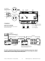
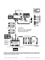
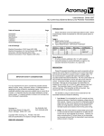
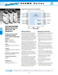
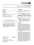
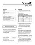
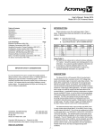
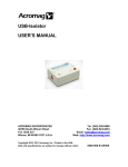
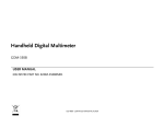
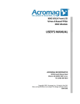
INSTRUCTIONS: Model 4683-TTM-x AC-Powered RS-485 Network Repeaters These instructions are presented in abbreviated form. Please visit our web site at www.acromag.com to register and obtain the complete User Manual 8500-237 for this product. MODEL DESCRIPTION Model 4683-TTM-1 4683-TTM-2 Power 115V AC 230V AC These devices are “rugged” RS-485 network repeaters used for isolating network signals and extending communication distances. Model 4683-TTM-x units are similar to the Acromag Model 4SCR-TTM-x models, but add field-selectable, End-OfLine (EOL) network terminations on board for both the A and B sides, and are UL approved. Operation is transparent to all other network devices and no handshaking is required. Up to 32 RS-485 devices can be driven. These repeaters are enclosed in a rugged aluminum enclosure and come ready to mount on any base plate, or can be installed into a NEMA enclosure for harsh environments. COMMUNICATION SPECIFICATIONS Baud Rates: DIP switch settings on unit for 300, 600, 1200, 2400, 4800, 9600, 19.2K, & 38.4K baud rates. Only one switch must be closed according to baud rate required for proper operation. RS-485 Bus Loading: One unit load equivalent. RS-485 Bus Drive: Complete RS-485 compliance for up to 32 unit loads (31 unit loads if a repeater is used). End-of-Line Termination Network: Refer to Figure 1. The EOL termination network is individually selected for both the A and B sides by a pair of shorting clips. The A side (input) is controlled by jumpers J1 & J2. The B side (output) is controlled by jumpers J3 & J4. The EOL network termination is enabled for the A side or the B side when the associated pair of jumpers are positioned over pins 1 and 2. The EOL termination is disabled (removed from circuit) when the pair of jumpers are positioned over pins 2 and 3. Duplex: Half duplex only. Installation is as simple as mounting, setting the baud rate, connecting and terminating the network, and connecting power. Data Format: Ten bits typical (1 start bit, 8 data bits, and 1 stop bit). Other formats are supported. FEATURES Status Indicators: Red power LED; red RS-485 bus fault LED’s, side A and side B; green transmit LED’s, A-to-B and B-to-A. ● No handshaking & No extra control lines required. ● Full I/O signal isolation. ● Supports baud rates of 300, 600, 1200, 2400, 4800, 9600, 19.2K, and 38.4K, switch-selectable. ● Field-selectable, End-of-Line (EOL) network terminators on both the A (input) and B (output) sides. Relative Humidity (RH): 10 to 95% RH (noncondensing), up to 40° C (104° F). ● Transient protection installed to help protect connected devices from destructive noise spikes and line transients. Power: 115VAC ±10%, 50/60 Hz, 0.05A (Model 4683-TTM-1); 230VAC ±10%, 50/60 Hz, 0.03A (Model 4683-TTM-2). ● Status LED’s indicate transmission direction, RS-485 bus fault conditions, and power. Power Line Fuse: 0.5A, 250V, 3AG type. Refer to Figure 1 for fuse location. ● 115VAC and 230VAC models supported. Isolation: Unit includes galvanic and optical isolation between RS-485 side A, RS-485 side B, AC power, and chassis ground. Common mode voltages of up to 250Vrms, or 354V DC (withstands a 1500V AC dielectric strength test for 1 minute without breakdown), are permitted on a continuous basis. This complies with test requirements outlined in ANSI C39.5-1974 for voltage ratings specified. OPERATION The Model 4683-TTM-1 & 4683-TTM-2 network repeaters are used to isolate and boost RS485 signals and extend network distance. Each repeater will permit the addition of up to another 32 devices to a network, and extend the communication distance another 4000 feet. The repeater has two “sides” referred to as side A and side B. Side A typically connects to the network towards the host (input side). Side B connects to the extended network (output side). Functionally, sides A and B are equivalent. Transient signal protection is provided on both RS-485 sides. When both RS485 lines are idle, each side is in the receive mode. When a one to zero transition is detected (signifying a start bit) on either side, the opposite side’s transmitter is enabled (half-duplex). The transmitter stays enabled for one character’s time (based on the baud rate switch setting). The character received is then passed through. The repeater receives AC power through a three-screw terminal strip. Input power is fused and isolated. Model 4683-TTM-1 units require 115VAC, 4683-TTM-2 units require 230VAC. PHYSICAL SPECIFICATIONS Operating Temperature: 0 to 70° C (32 to 158° F). RFI Resistance: Withstands an RFI field strength of 10V per meter at 27MHz, 151MHz, and 467MHz with no digital effect, per SAMA PMC 33.1 test procedures. Line Noise Effects: Field and power line terminals withstand ANSI/IEEE C37.90-1978 Surge Withstanding Capability (SWC) Test with no component failures. Unit is tested to a standardized test waveform that is representative of surges (high-freq. transient electrical interference), observed in actual installations. Communication Connections: Network repeater – both RS485 connections use modular terminal blocks with screw clamps. Wire range is 14 to 26 AWG CSA approved. Power Wire Connections: Network repeater terminal block. See label on unit for power to be applied to unit. Approvals: UL Listed, CSA Certified file LR25710. Shipping Weight: 3.0 pounds (1.4 kg) packed per unit. Acromag Incorporated, 30765 South Wixom Road • P.O. Box 437 • Wixom, MI • 48393-7037, USA Phone: (248) 624-1541 • Fax: (248) 624-9234 • E-mail: [email protected] • On-Line: http://www.acromag.com Copyright 1990, Acromag, Inc. Printed in the USA. 8500-267-B04C016 REPEATER INSTALLATION Setting The Baud Rate Mounting The unit includes an 8-position DIP switch (S1) along the bottom edge. This switch is used to set the baud rate of the repeater. Only the switch that corresponds to the required baud rate should be closed (refer to label information next to S1)—all other switches must be left in the OPEN position. Refer to Figure 1 below for mounting and clearance dimensions. This device is packaged in a rugged aluminum enclosure and no auxiliary enclosure is required for most applications. Mounting holes are provided for surface mounting the unit. You may use an auxiliary enclosure to protect the unit in unfavorable environments or vulnerable locations. Electrical Connections (Refer To Drawing 4501-783) Terminals can accommodate wire from 14-26 AWG, solid or stranded. Termination Jumpers 4.30 3.70 (109.22) (93.98) RTN 24VDC 24VDC D D RT RT RS-485 SIDE B D NC D COM RT acromag POWER 0.30 (7.62) TYP RT RS-485 SIDE A Model 4683-TTM-X units include selectable End-Of-Line (EOL) termination resistors that can be enabled or disabled by positioning jumper blocks on headers installed on the circuit board (see Figure 2). You will have to remove the top cover to gain access to these jumpers. Be sure to turn power OFF before removing the cover or setting these jumpers. Simply remove the single screw on each side of the enclosure and slide the top cover off. Refer to Figure 2 of the following page to locate and set these jumpers as required for your installation. Optionally, you may leave these jumpers in their disabled position and attach 120Ω termination resistors externally, between the RT terminals adjacent to the network connections. COM 1. Network - Input (Side A) & Output (Side B): Connect unit as shown in Figures 3 and 4. Be sure to enable EOL termination as required at the ends of the network. Make sure the baud rate DIP switches are set to match the data rate of the network. 2. Power: Connect AC power as shown in Figure 4 according to model number. Input power is fused (3AG type, 0.5A, 250V). Refer to Figure 2 to locate this fuse if the red power LED fails to light with power applied. 3. Ground: Ground unit at AC input ground (G) terminal. The chassis is common to this earth ground connection. Any RS-485 network will require that the network be properly terminated at the ends of a network, or network segment. Termination is usually found at the first and last node of a network segment. Since a repeater is used to segment a network, two sets of termination resistors will be required. One at the input side, one at the output side. FAULT A 1 - 300 2 - 600 3 - 600 4 - 2400 5 - 4800 6 - 9600 BAUD 7 - 19.2K RATE 8 - 38.4K 1 2 3 4 5 6 7 8 S1 TX B - A 6.40 (162.56) TX A - B FAULT B 0.30 (7.62) TYP 7.0 (177.80) FIGURE 1 MODEL 4683-TTM-X REPEATER MODEL 4SCR-TTM-X REPEATER MECHANICAL DIMENSIONS 2.10 (53.34) Acromag, Inc. Phone: (248) 624-1541 • Fax: (248) 624-9234 -2- • E-mail: [email protected] • On-Line: http://www.acromag.com EOL Jumpers Side A (IN) EOL JUMPERS EQUIVALENT CIRCUIT (4683 UNITS ONLY) 1 2 3 1 2 3 J1 J2 Status LED's J1 J2 EOL EOL DISABLED ENABLED Vcc FAULT B JUMPER PAIR (ONE SIDE) Status LED's Baud Rate Switches TX A - B TX B - A S1 1200 OHMS 1 - 300 BAUD 2 - 600 RATE 3 - 600 4 - 2400 8 7 6 5 4 3 2 1 D FUSE 3AG 0.5A, 250V EOL Jumpers Side B (OUT) 1 2 3 1 2 3 FIGURE 2 RS-485 SIDE B MODEL 4683-TTM-1 REPEATER MODEL 4683-TTM-2 REPEATER End-of-Line (EOL) Termination Jumper Locations. Input Power Fuse Location. COM D RS-485 SIDE A TR D D EOL ENABLED TR EOL DISABLED J1 J2 NC J4 J3 24VDC J4 J3 RS-485 SIDE B J4 J3 COM 1 2 3 D 1 2 3 TR 1 1200 OHMS D 2 F1 TR 3 POWER REMOVE THIS SCREW ON EACH SIDE TO REMOVE COVER RTN 1 COM 2 24VDC D 3 220 OHMS FAULT A 5 - 4800 6 - 9600 7 - 19.2K 8 - 38.4K G W L1 4683-TTM-1 (115VAC) G L2 L1 4683-TTM-2 (230VAC) RS-485 SIDE A D COM D AC (HI) AC (LO) GROUND D NETWORK CONNECTIONS FIGURE 3 MODEL 4683-TTM-X REPEATER STATION CONFIGURATION HOST PC RS-232 RS-485 1 - 300 5 - 4800 2 - 600 6 - 9600 3 - 600 7 - 19.2K 4 - 2400 8 - 38.4K A-N32 Acromag R 1 R 1 R 1 R UP TO 32 NODES PER NETWORK SEGMENT 1 2 3 4 5 6 7 8 232 > 485 RS485 FAULT 485 > 232 POWER FAULT A 1 - 300 5 - 4800 2 - 600 6 - 9600 3 - 600 7 - 19.2K 4 - 2400 8 - 38.4K D D RT RTN 24VDC RT 24VDC 1 R ANY RS-485 DEVICE NO TERMINATION RESISTOR DFT 0 R Acromag RUN ST 1 R ST DFT 0 DFT 1 0 R UP TO 32 NODES PER NETWORK SEGMENT 1 R 1 2 3 4 5 6 7 8 BAUD RATE S1 TX B - A TX A - B FAULT B SIGNAL REPEATER RS232-TO-RS485 SIGNAL CONVERTER 1 Acromag RUN ST DFT 0 B-N32 Acromag RUN ST DFT 0 MODEL 4683-TTM-1 MODEL 4683-TTM-2 acromag BAUD RATE S1 COM DFT 0 NC DFT 0 Acromag RUN ST COM DFT 0 B-N5 B-N4 Acromag RUN ST RS-485 SIDE B 1 B-N3 B-N1 RUN ST RT D D RTN 24VDC RT RT COM 24VDC Tx Rx COM TB 2 RS-485 TB 1 RS-232C AC INPUT MODEL 4SCC-TTM-1 MODEL 4SCC-TTM-2 POWER DFT 0 RS-485 RS-485 B-N2 Acromag RUN ST D Acromag RUN ST OUTPUT (SIDE B) A-N5 A-N4 Acromag RUN D A-N1 RT A-N3 A-N2 120 INPUT (SIDE A) RS-485 RS-485 SIDE A 120 OHM TERMINATION RESISTOR REQUIRED THIS END acromag NETWORK SEGMENT 2 (EXTENDED NETWORK) UP TO 4000 FEET NETWORK SEGMENT 1 UP TO 4000 FEET SIDE-A EOL TERMINATION JUMPERS ENABLED SIDE-B EOL TERMINATION JUMPERS ENABLED ANY RS-485 DEVICE 120 OHM TERMINATION RESISTOR REQUIRED AT END OF NETWORK OR LAST DEVICE ONLY OPTIONALLY, YOU MAY CONNECT TERMINATION RESISTORS EXTERNALLY BETWEEN THE RT TERMINALS ADJACENT TO THE NETWORK CONNECTIONS FOR SIDE A AND SIDE B, BUT THE INTERNAL JUMPERS MUST BE SET TO DISABLED WHEN USING EXTERNAL TERMINATION. The station configuration drawing of Figure 3 is for general illustration purposes only. Johnson Controls customers should instead refer to the Metasys® Network Technical Manual for N2 Bus Communication connections using the 4683-TTM-x repeater. Acromag, Inc. Phone: (248) 624-1541 • Fax: (248) 624-9234 -3- • E-mail: [email protected] • On-Line: http://www.acromag.com HOST PC TRANSMIT DIRECTION RS232-TO-RS485 AND RS485-TO-RS232 RED RS485 FAULT LED SET BAUD RATE AT S1 RED POWER LED 232 > 485 S1 1 - 300 5 - 4800 2 - 600 6 - 9600 3 - 600 7 - 19.2K 4 - 2400 8 - 38.4K BAUD RATE 8 7 6 5 4 3 2 1 S1 - SET BAUD RATE TO MATCH BAUD RATE OF NETWORK. RS232 TO RS485 CONVERTER MODEL 4SCC-TTM-X acromag S1 - BAUD RATE 1 - 300 5 - 4800 2 - 600 6 - 9600 3 - 1200 7 - 19.2K 4 - 2400 8 - 38.4K RS232 CONNECTIONS TO HOST COMPUTER -1 OPTION -2 OPTION 115VAC 230VAC L1 AC (HI) L1 AC (HI) W AC (LO) L2 AC (LO) G Ground G Ground POWER B 5 6 7 8 9 10 11 12 13 TB 1 RS-232C 1 2 3 4 AC INPUT Rx COM TB 2 RS-485 Tx D D TR TR RTN COM 24VDC 24VDC NC A-N1 ABC L1 W 115VAC L1 L2 230VAC 2 TX TX 3 RX RTS CTS DB25 1 2 DE9 C 7 COM RS232 B R C A-N3 DSR COM CD HOST DE9 A A-N2 RX 2 TX TX 3 RX COM 5 COM R NOTE: JUMPERED PINS ARE NULL-MODEM CONNECTIONS WHICH ALLOW COMMUNICATION BETWEEN THE HOST AND ACROMAG SERIES 4100/4200 I/O STATIONS. UP TO 32 NODES PER NETWORK SEGMENT ANY RS485 DEVICES RX OR 3 4 5 120 OHM TERMINATION REQUIRED A TO HOST GROUND POWER CONNECTION HOST DB25 SIGNALS AT CONVERTER 14 15 16 17 18 19 20 21 22 23 24 25 RS485 FAULT 6 7 8 9 485 > 232 FIGURE 4 A-N30 R MODEL 4SCC-TTM-X CONVERTER MODEL 4683-TTM-X REPEATER SYSTEM CONNECTIONS R A-N31 -1 OPTION -2 OPTION 115VAC 230VAC L1 AC (HI) L1 AC (HI) W AC (LO) L2 AC (LO) G Ground G Ground RS485 B-N3 B-N2 SEE UNIT LABEL TO VERIFY POWER REQUIREMENTS B-N5 B-N4 B-N32 B-N1 A-N32 24VDC D RTN COM 24VDC D RT RT NC COM RS-485 SIDE B D D RT RT NC RS-485 SIDE A IMPORTANT: MODEL 4683-TTM-X UNITS INCLUDE INTERNAL, FIELD SELECTABLE END-OF-LINE (EOL) TERMINATION RESISTORS FOR THE A AND B SIDES. THESE ARE ENABLED VIA INTERNAL JUMPERS. DO NOT USE EXTERNAL TERMINATION WITH INTERNAL EOL JUMPERS ENABLED. EXTENDED NETWORK RS485 RS485 REPEATER MODEL 4683-TTM-X acromag R R R R UP TO 32 NODES PER NETWORK SEGMENT NOTE: SIDE-A AND SIDE-B EOL TERMINATION JUMPERS ENABLED POWER FAULT A 1 - 300 5 - 4800 2 - 600 6 - 9600 BAUD 3 - 600 7 - 19.2K RATE 4 - 2400 8 - 38.4K 1 2 3 4 5 6 7 8 S1 TX B - A TX A - B FAULT B ANY RS-485 DEVICE RED POWER LED RED RS485 FAULT LED (SIDE B) R S1 - SET BAUD RATE TO MATCH BAUD RATE OF NETWORK. RED RS485 FAULT LED (SIDE B) TRANSMIT DIRECTION RS232-TO-RS485 AND RS485-TO-RS232 120 OHM TERMINATION RESISTOR REQUIRED AT END OF NETWORK OR LAST DEVICE ONLY S1 - BAUD RATE 1 - 300 5 - 4800 2 - 600 6 - 9600 3 - 1200 7 - 19.2K 4 - 2400 8 - 38.4K The system connection drawing of Figure 4 is for general illustration purposes only. Johnson Controls customers should instead refer to the Metasys® Network Technical Manual for N2 Bus Communication connections using the 4683-TTM-x repeater. Acromag, Inc. Phone: (248) 624-1541 • Fax: (248) 624-9234 -4- • E-mail: [email protected] • On-Line: http://www.acromag.com