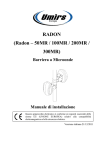
1
Liebert® eXL™ Battery System
Installation Manual
BATTERY CABINET PRECAUTIONS
The following warning applies to all battery cabinets supplied with UPS systems. Additional
warnings and cautions applicable to battery cabinets may be found in Important Safety
Instructions beginning on page 1.
! WARNING
Internal battery strapping must be verified prior to moving a battery cabinet (after initial
installation).
• Battery cabinets contain non-spillable batteries.
• Keep units upright.
• Do not stack.
• Do not tilt.
Failure to heed this warning could result in smoke, fire or electric hazard.
Call 1-800-LIEBERT prior to moving battery cabinets (after initial installation).
! AVERTISSEMENT
L’arrimage des batteries internes doit être vérifié par le fabricant avant de déplacer une
armoire de batteries (après l’installation initiale).
• Les armoires de batteries contiennent des batteries étanches.
• Maintenir les systèmes à la verticale.
• Ne pas empiler.
• Ne pas incliner.
Le non-respect de ces consignes comporte des risques liés à la fumée, au feu ou à l’électricité.
Composez le 1 800 LIEBERT avant de déplacer des armoires de batteries (après l’installation
initiale).
CONTACTING EMERSON NETWORK POWER® FOR SUPPORT
To contact the Emerson Network Power Liebert® Services for information or repair service in the
United States, call 1-800-LIEBERT (1-800-543-2378). Liebert Services offers a complete range of
startup services, repair services, preventive maintenance plans and service contracts.
For repair or maintenance service outside the 48 contiguous United States, contact Liebert Services,
if available in your area.
For Liebert Services to assist you promptly, have the following information available:
Part Numbers:
Serial Numbers:
Rating:
Date Purchased:
Date Installed:
Location:
Battery Voltage:
Battery Reserve Time:
Product Warranty Registration
To register for warranty protection, visit the Service and Support section of our Web site at:
www.liebert.com
Click on Product Registration and fill out the form.
TABLE OF CONTENTS
BATTERY CABINET PRECAUTIONS . . . . . . . . . . . . . . . . . . . . . . . . . . . . . . . . . INSIDE FRONT COVER
CONTACTING EMERSON NETWORK POWER® FOR SUPPORT . . . . . . . . . . . . . . INSIDE FRONT COVER
IMPORTANT SAFETY INSTRUCTIONS . . . . . . . . . . . . . . . . . . . . . . . . . . . . . . . . . . . . . . . . . . . . . . . .1
SAVE THESE INSTRUCTIONS . . . . . . . . . . . . . . . . . . . . . . . . . . . . . . . . . . . . . . . . . . . . . . . . .1
1.0
MECHANICAL INSTALLATION . . . . . . . . . . . . . . . . . . . . . . . . . . . . . . . . . . . . . . . . . . . . . . . .5
1.1
Introduction . . . . . . . . . . . . . . . . . . . . . . . . . . . . . . . . . . . . . . . . . . . . . . . . . . . . . . . . . . . . . . . . 5
1.2
Preliminary Checks . . . . . . . . . . . . . . . . . . . . . . . . . . . . . . . . . . . . . . . . . . . . . . . . . . . . . . . . . . 5
1.3
Environmental Considerations . . . . . . . . . . . . . . . . . . . . . . . . . . . . . . . . . . . . . . . . . . . . . . . . . 5
1.3.1
1.3.2
1.4
Battery Room . . . . . . . . . . . . . . . . . . . . . . . . . . . . . . . . . . . . . . . . . . . . . . . . . . . . . . . . . . . . . . . . 5
Storage . . . . . . . . . . . . . . . . . . . . . . . . . . . . . . . . . . . . . . . . . . . . . . . . . . . . . . . . . . . . . . . . . . . . . 5
Positioning . . . . . . . . . . . . . . . . . . . . . . . . . . . . . . . . . . . . . . . . . . . . . . . . . . . . . . . . . . . . . . . . . 6
1.4.1
1.4.2
1.4.3
Moving the Cabinets. . . . . . . . . . . . . . . . . . . . . . . . . . . . . . . . . . . . . . . . . . . . . . . . . . . . . . . . . . . 6
Clearances. . . . . . . . . . . . . . . . . . . . . . . . . . . . . . . . . . . . . . . . . . . . . . . . . . . . . . . . . . . . . . . . . . . 7
Raised Floor Mounting . . . . . . . . . . . . . . . . . . . . . . . . . . . . . . . . . . . . . . . . . . . . . . . . . . . . . . . . . 7
1.5
System Composition . . . . . . . . . . . . . . . . . . . . . . . . . . . . . . . . . . . . . . . . . . . . . . . . . . . . . . . . . . 7
2.0
BATTERY INSTALLATION . . . . . . . . . . . . . . . . . . . . . . . . . . . . . . . . . . . . . . . . . . . . . . . . . . .8
2.1
Safety . . . . . . . . . . . . . . . . . . . . . . . . . . . . . . . . . . . . . . . . . . . . . . . . . . . . . . . . . . . . . . . . . . . . . 8
2.2
Layout . . . . . . . . . . . . . . . . . . . . . . . . . . . . . . . . . . . . . . . . . . . . . . . . . . . . . . . . . . . . . . . . . . . . . 8
2.3
Cable Entry. . . . . . . . . . . . . . . . . . . . . . . . . . . . . . . . . . . . . . . . . . . . . . . . . . . . . . . . . . . . . . . . 10
2.4
Power Connection . . . . . . . . . . . . . . . . . . . . . . . . . . . . . . . . . . . . . . . . . . . . . . . . . . . . . . . . . . . 10
2.4.1
2.4.2
2.4.3
2.4.4
Connected System . . . . . . . . . . . . . . . . . . . . . . . . . . . . . . . . . . . . . . . . . . . . . . . . . . . . . . . . . . .
Stand-Alone System . . . . . . . . . . . . . . . . . . . . . . . . . . . . . . . . . . . . . . . . . . . . . . . . . . . . . . . . .
Attached/Detached System . . . . . . . . . . . . . . . . . . . . . . . . . . . . . . . . . . . . . . . . . . . . . . . . . . . .
Grounding . . . . . . . . . . . . . . . . . . . . . . . . . . . . . . . . . . . . . . . . . . . . . . . . . . . . . . . . . . . . . . . . . .
10
10
11
11
2.5
Control Connection. . . . . . . . . . . . . . . . . . . . . . . . . . . . . . . . . . . . . . . . . . . . . . . . . . . . . . . . . . 11
2.6
Alber Monitoring System—Optional . . . . . . . . . . . . . . . . . . . . . . . . . . . . . . . . . . . . . . . . . . . . 14
2.7
External Battery Room Temperature Sensor—Optional . . . . . . . . . . . . . . . . . . . . . . . . . . . . 14
3.0
INSTALLATION DRAWINGS . . . . . . . . . . . . . . . . . . . . . . . . . . . . . . . . . . . . . . . . . . . . . . . . .15
4.0
SPECIFICATIONS . . . . . . . . . . . . . . . . . . . . . . . . . . . . . . . . . . . . . . . . . . . . . . . . . . . . . . . .33
i
FIGURES
Figure 1
Figure 2
Figure 3
Figure 4
Figure 5
Figure 6
Figure 7
Figure 8
Figure 9
Figure 10
Figure 11
Figure 12
Figure 13
Figure 14
Figure 15
Figure 16
Figure 17
Figure 18
Figure 19
Figure 20
Figure 21
Figure 22
Figure 23
Figure 24
Figure 25
Figure 26
Shipping bolts—Top-Terminal Battery Cabinet . . . . . . . . . . . . . . . . . . . . . . . . . . . . . . . . . . . . . . . . 7
Battery cabinets connected, attached to UPS . . . . . . . . . . . . . . . . . . . . . . . . . . . . . . . . . . . . . . . . . . 9
Battery cabinets connected, detached from UPS . . . . . . . . . . . . . . . . . . . . . . . . . . . . . . . . . . . . . . . 9
Stand-alone battery cabinets, detached from UPS . . . . . . . . . . . . . . . . . . . . . . . . . . . . . . . . . . . . . 10
Wiring external interface board in UPS to battery interface board in battery cabinet . . . . . . . . 12
Control cable layout—Liebert eXL UPS to Liebert eXL Battery Cabinet . . . . . . . . . . . . . . . . . . . 13
Battery temperature sensor control connection . . . . . . . . . . . . . . . . . . . . . . . . . . . . . . . . . . . . . . . 14
Outline drawing, Liebert Top-Terminal Battery Cabinet . . . . . . . . . . . . . . . . . . . . . . . . . . . . . . . 15
Main components, Liebert Top-Terminal Battery Cabinet . . . . . . . . . . . . . . . . . . . . . . . . . . . . . . 16
Terminal details, Liebert Top-Terminal Battery Cabinet . . . . . . . . . . . . . . . . . . . . . . . . . . . . . . . 17
Front Terminal Battery Cabinet shipping split . . . . . . . . . . . . . . . . . . . . . . . . . . . . . . . . . . . . . . . 18
Front Terminal Battery Cabinet outline drawing. . . . . . . . . . . . . . . . . . . . . . . . . . . . . . . . . . . . . . 19
Front Terminal Battery Cabinet main components, layout . . . . . . . . . . . . . . . . . . . . . . . . . . . . . . 20
Front terminal detail drawing . . . . . . . . . . . . . . . . . . . . . . . . . . . . . . . . . . . . . . . . . . . . . . . . . . . . . 21
Liebert eXL Stand-Alone Junction Cabinet terminal wiring . . . . . . . . . . . . . . . . . . . . . . . . . . . . . 22
Liebert eXL Attached Junction Cabinet—terminal detail and outline drawing . . . . . . . . . . . . . . 23
Liebert eXL Battery Cabinet control wiring . . . . . . . . . . . . . . . . . . . . . . . . . . . . . . . . . . . . . . . . . . 24
Attached battery cabinet connections . . . . . . . . . . . . . . . . . . . . . . . . . . . . . . . . . . . . . . . . . . . . . . . 25
Ground strap location for connected cabinets . . . . . . . . . . . . . . . . . . . . . . . . . . . . . . . . . . . . . . . . . 25
Liebert eXL Top-Terminal Battery Cabinet interconnect wiring to Liebert eXL Stand-Alone
Junction Cabinet . . . . . . . . . . . . . . . . . . . . . . . . . . . . . . . . . . . . . . . . . . . . . . . . . . . . . . . . . . . . . . . . 26
Typical Alber battery monitoring connections . . . . . . . . . . . . . . . . . . . . . . . . . . . . . . . . . . . . . . . . 27
Alber battery monitoring wiring to multiple battery cabinets . . . . . . . . . . . . . . . . . . . . . . . . . . . . 28
Alber battery monitoring assembly diagram. . . . . . . . . . . . . . . . . . . . . . . . . . . . . . . . . . . . . . . . . . 29
Top-Terminal battery configuration . . . . . . . . . . . . . . . . . . . . . . . . . . . . . . . . . . . . . . . . . . . . . . . . 30
Front-Terminal battery configuration . . . . . . . . . . . . . . . . . . . . . . . . . . . . . . . . . . . . . . . . . . . . . . . 31
Busbar connection between Battery Cabinet and Attached Junction Cabinet . . . . . . . . . . . . . . . 32
TABLES
Table 1
Table 2
Table 3
Table 4
Table 5
Table 6
Table 7
Table 8
Table 9
Table 10
Table 11
Table 12
Liebert eXL Top-Terminal Battery Cabinet interconnect wiring to Liebert eXL Junction
Cabinet. . . . . . . . . . . . . . . . . . . . . . . . . . . . . . . . . . . . . . . . . . . . . . . . . . . . . . . . . . . . . . . . . . . . . . . .
Alber battery monitoring assembly connections . . . . . . . . . . . . . . . . . . . . . . . . . . . . . . . . . . . . . . .
Liebert eXL Battery Cabinet specifications. . . . . . . . . . . . . . . . . . . . . . . . . . . . . . . . . . . . . . . . . . .
Liebert eXL Junction Cabinet specifications . . . . . . . . . . . . . . . . . . . . . . . . . . . . . . . . . . . . . . . . . .
Alber® battery monitoring option specifications . . . . . . . . . . . . . . . . . . . . . . . . . . . . . . . . . . . . . . .
DC currents for Liebert eXL modules . . . . . . . . . . . . . . . . . . . . . . . . . . . . . . . . . . . . . . . . . . . . . . .
Liebert eXL Battery Cabinet internal breaker . . . . . . . . . . . . . . . . . . . . . . . . . . . . . . . . . . . . . . . .
Liebert eXL Battery Cabinet approximate weights . . . . . . . . . . . . . . . . . . . . . . . . . . . . . . . . . . . .
Recommended external conduit and cable sizes from Liebert eXL UPS to DC source . . . . . . . . .
Recommended lug sizes . . . . . . . . . . . . . . . . . . . . . . . . . . . . . . . . . . . . . . . . . . . . . . . . . . . . . . . . . .
Torque specifications, unless otherwise labeled . . . . . . . . . . . . . . . . . . . . . . . . . . . . . . . . . . . . . . .
Battery torque values . . . . . . . . . . . . . . . . . . . . . . . . . . . . . . . . . . . . . . . . . . . . . . . . . . . . . . . . . . . .
ii
26
29
33
34
34
34
35
35
36
36
37
37
Important Safety Instructions
IMPORTANT SAFETY INSTRUCTIONS
SAVE THESE INSTRUCTIONS
This manual contains important instructions that should be followed during installation of your
Liebert eXL Battery Cabinet and accessories. Read this manual thoroughly, paying special attention
to the sections that apply to your installation, before working with the battery system. Retain this
manual for use by installing personnel.
! WARNING
Risk of electrical shock. Can cause personal injury and death.
Check for voltage with both AC and DC voltmeters before working within the UPS. Check for
voltage with both AC and DC voltmeters before making contact.
Only properly trained and qualified personnel wearing appropriate safety headgear, gloves,
shoes and glasses should be involved in installing the UPS or preparing the UPS for
installation. When performing maintenance with any part of the equipment under power,
service personnel and test equipment should be standing on rubber mats.
Lead-acid batteries contain hazardous materials. Batteries must be handled, transported and
recycled or discarded in accordance with federal, state and local regulations. Because lead is a
toxic substance, lead-acid batteries must be recycled rather than discarded.
Do not dispose of battery or batteries in a fire. The battery may explode.
Do not open or mutilate the battery or batteries. Released electrolyte is harmful to the skin
and eyes. It is toxic.
The following precautions must be observed when working on batteries:
• Remove watches, rings and other metal objects.
• Use tools with insulated handles.
• Wear rubber gloves and boots.
• Do not lay tools or metal parts on top of batteries.
• Disconnect charging source prior to connecting or disconnecting battery terminals.
• Determine whether the battery is grounded. If it is grounded, remove source of ground.
Contact with any part of a grounded battery can result in electrical shock. The likelihood of
such shock will be reduced if such grounds are removed during installation and maintenance.
1
Liebert® eXL™ Battery System
Important Safety Instructions
! AVERTISSEMENT
Risque de décharge électrique pouvant causer des blessures graves, voire mortelles.
Vérifiez les tensions au moyen de voltmètres c.a. et c.c. avant d'utiliser le système ASC.
Vérifiez les tensions avec des voltmètres c.a. et c.c. avant d'établir tout contact.
Seuls des employés qualifiés et dûment formés portant un casque, des gants, des chaussures
et des lunettes de écurité adéquats doivent se charger d’installer le système ASC ou de le
préparer pour l'installation. Les responsables de l'entretien et l’équipement d’essai doivent
reposer sur des tapis de caoutchouc lors de toute intervention sur une pièce d’équipement sous
tension.
Les batteries au plomb-acide renferment des matières dangereuses. Les batteries doivent être
manipulées, transportées, recyclées ou jetées conformément aux règlements fédéraux,
provinciaux et municipaux. Étant donné que le plomb est une substance toxique, les batteries
au plomb-acide doivent être recyclées plutôt que mises au rebut.
Ne jetez jamais de batteries au feu car elles risquent d’exploser.
Vous ne devez ni ouvrir ni percer les batteries, car l'électrolyte qui s'en écoulerait est nocif
pour la peau et les yeux. Cet électrolyte est toxique.
Lorsque vous travaillez avec des batteries, prenez les précautions suivantes :
•
•
•
•
•
Retirez montre, bagues et tout autre objet métallique.
Utilisez des outils dont le manche est isolé.
Portez des gants et des bottes de caoutchouc.
Ne posez aucun outil ni pièce métallique sur le dessus d’une batterie.
Déconnectez la source de chargement avant de brancher ou de débrancher les bornes d’une
batterie.
• Vérifiez si la batterie est mise à la terre. Le cas échéant, éliminez la cause de la mise à la
terre.
Le contact avec toute partie d'une batterie mise à la terre peut provoquer une décharge
électrique. Pour réduire de tels risques d'accident, débranchez les prises de terre avant de
procéder à l’installation ou à l'entretien.
! WARNING
Risk of electric shock. Can cause personal injury and death.
In case of fire involving electrical equipment, use only carbon dioxide fire extinguishers or
those approved for use in fighting electrical fires.
! AVERTISSEMENT
Risque de décharge électrique pouvant causer des blessures graves, voire mortelles.
En cas d'incendie associé à du matériel électrique, n'utilisez que des extincteurs à dioxyde de
carbone ou homologués pour la lutte contre les incendies d’origine électrique.
! WARNING
Risk of heavy unit falling over. Improper handling can cause equipment damage, injury or
death.
Exercise extreme care when handling battery cabinets to avoid equipment damage or injury
to personnel. The battery system cabinets weigh up to 3760 to 8990 lb. (1706 to 4078kg).
Locate center of gravity symbols
and determine unit weight before handling each
cabinet. Test lift and balance the cabinets before transporting. Maintain minimum tilt from
vertical at all times.
Slots at the base of the module cabinets are intended for forklift use. Base slots will support
the unit only if the forks are completely beneath the unit.
Read all of the following instructions before attempting to move, lift, or remove packaging
from unit, or prepare unit for installation.
Liebert® eXL™ Battery System
2
Important Safety Instructions
! AVERTISSEMENT
Le centre de gravité élevé de l’appareil présente un risque de renversement. Une mauvaise
manutention peut entraîner des dommages matériels, des blessures et même la mort.
Faites preuve d'une extrême prudence lors de la manutention des armoires ASC afin d’éviter
de les endommager ou de blesser le personnel. Le module ASC pèse jusqu'à 2 601kg (5 735lb).
Identifiez les symboles de centre de gravité
et déterminez le poids de l'appareil avant de
manipuler chaque armoire. Testez le levage et l’équilibre des armoires avant de transporter
l'appareil. Maintenez en tout temps l'inclinaison verticale minimale.
Les fentes situées à la base des armoires du module sont conçues pour utiliser le chariot
élévateur. Les fentes situées à la base peuvent soutenir le système seulement si les fourches
se trouvent complètement sous le système.
Lisez toutes les instructions ci-dessous avant de tenter de déplacer, lever, déballer ou
préparer le système en vue de son installation.
! WARNING
Risk of electrical shock and fire. Can cause equipment damage, personal injury or death.
Under typical operation and with all UPS doors closed, only normal safety precautions are
necessary. The area around the UPS system should be kept free of puddles of water, excess
moisture and debris.
Only test equipment designed for troubleshooting should be used. This is particularly true for
oscilloscopes. Always check with an AC and DC voltmeter to ensure safety before making
contact or using tools. Even when the power is turned Off, dangerously high potential electric
charges may exist at the capacitor banks and at the DC connections.
All wiring must be installed by a properly trained and qualified electrician. All power and
control wiring must comply with all applicable national, state and local codes.
One person should never work alone, even if all power is disconnected from the equipment. A
second person should be standing by to assist and to summon help in case of an accident.
! AVERTISSEMENT
Risque de décharge électrique et d’incendie. Pouvant entraîner des dommages matériels, des
blessures et même la mort.
Les précautions de sécurité habituelles suffisent lorsque le système ASC est en mode de
fonctionnement normal et que toutes les portes sont fermées. La zone entourant le système
ASC doit être exempte de flaques d'eau, d’humidité excessive et de débris.
Seuls des équipements d’essai conçus pour le dépannage doivent être utilisés. Cette mise en
garde couvre notamment les oscilloscopes. Utilisez toujours un voltmètre c.a. et c.c. pour
vérifier les tensions avant d'établir un contact ou d’utiliser des appareils. Des tensions
dangereusement élevées peuvent demeurer dans les batteries de condensateurs et au niveau
des raccords c.c., même une fois l'alimentation coupée.
Tous les raccords doivent être effectués par un électricien dûment formé et qualifié. Tous les
câbles d’alimentation et de commande doivent être conformes aux codes nationaux et locaux
en vigueur.
Une personne ne devrait jamais travailler seule, même si toute l’alimentation d’entrée est
coupée. Une deuxième personne devrait toujours être présente pour porter assistance ou
chercher de l'aide en cas d’accident.
NOTE
Materials sold hereunder cannot be used in the patient vicinity (e.g., use where UL, cUL or IEC
60601-1 is required). Medical applications such as invasive procedures and electrical life
support equipment are subject to additional terms and conditions.
3
Liebert® eXL™ Battery System
Important Safety Instructions
NOTICE
This unit complies with the limits for a Class A digital device, pursuant to Part 15 Subpart J
of the FCC rules. These limits provide reasonable protection against harmful interference in a
commercial environment. This unit generates, uses and radiates radio frequency energy and,
if not installed and used in accordance with this instruction manual, may cause harmful
interference to radio communications. Operation of this unit in a residential area may cause
harmful interference that the user must correct at his own expense.
Liebert® eXL™ Battery System
4
Mechanical Installation
1.0
MECHANICAL INSTALLATION
1.1
Introduction
This following section describes the requirements that must be taken into account when planning the
positioning and cabling of the Liebert eXL battery equipment.
This chapter is a guide to general procedures and practices that should be observed by the installing
engineer. The particular conditions of each site will determine the applicability of such procedures.
NOTICE
Do not apply electrical power to the UPS equipment before the arrival of the commissioning
engineer.
1.2
Preliminary Checks
Before installing the battery equipment, please carry out the following preliminary checks:
• Visually examine the equipment for transit damage, both internally and externally. Report any
damage to the shipper immediately.
• Verify that the correct equipment is being installed. The equipment supplied has an identification
tag inside the main door.
• Verify that the battery room satisfies the environmental conditions stipulated in the equipment
specification, paying particular attention to the ambient temperature and air exchange system.
1.3
Environmental Considerations
1.3.1
Battery Room
Batteries should be mounted in an environment where the temperature is consistent and even over
the whole battery. Temperature is a major factor in determining the battery life and capacity. Typical
battery manufacturer performance data are quoted for an operating temperature between 68 and
77°F (20 and 25°C). Operating above this range will reduce the battery life while operation below this
range will reduce the battery capacity.
Battery Temperature
In a normal installation, the battery temperature should be kept between 59 and 77°F (15°C and
25°C).
NOTE
Keep batteries away from main heat sources, main air inlets, etc.
1.3.2
Storage
Should the equipment not be installed immediately, it must be stored in a room for protection against
excessive humidity and heat sources (see Table 3).
NOTICE
Risk of deep discharge can cause permanent damage to batteries.
An unused battery must be recharged periodically as recommended by the battery
manufacturer.
5
Liebert® eXL™ Battery System
Mechanical Installation
1.4
Positioning
The cabinet is structurally designed to handle lifting from the base.
Power terminals, auxiliary terminals blocks and power switches are accessed from the front and top.
Removable panels on the top are secured to the chassis by screws. The door can be opened to give
access to the power connections bars, auxiliary terminal blocks and power isolators. The front door
can be opened 180° for easier service and more flexibility in installation.
1.4.1
Moving the Cabinets
The route to be travelled between the point of arrival and the unit’s installation location must be
planned to make sure that all passages are wide enough for the unit and that floors are capable of
supporting its weight (for instance, check that doorways, lifts, ramps, etc., are adequate and that
there are no impassable corners or changes in the level of corridors).
Ensure that the cabinet weight is within the designated surface weight loading (kg/cm2) of any
handling equipment. See Table 3 for weight details.
Ensure that any lifting equipment used to move the battery equipment has sufficient lifting capacity.
Battery system equipment can be handled by a forklift or similar equipment.
Because the weight distribution in the cabinet is not symmetrical, use extreme care during handling
and transporting.
When moving the unit by forklift, care must be taken to protect the panels. Do not exceed a 15° tilt
with the forklift. Bottom structure will support the unit only if the forks are completely beneath the
unit.
Handling the unit with straps is not authorized.
! WARNING
Risk of heavy unit falling over. Improper handling can cause equipment damage, injury or
death.
Exercise extreme care when handling battery cabinets to avoid equipment damage or injury
to personnel. The battery system cabinets weigh up to 3760 to 8990 lb. (1706 to 4078kg).
Locate center of gravity symbols
and determine unit weight before handling each
cabinet. Test lift and balance the cabinets before transporting. Maintain minimum tilt from
vertical at all times.
Slots at the base of the module cabinets are intended for forklift use. Base slots will support
the unit only if the forks are completely beneath the unit.
Read all of the following instructions before attempting to move, lift, or remove packaging
from unit, or prepare unit for installation
! AVERTISSEMENT
Le centre de gravité élevé de l'appareil présente un risque de renversement. Une mauvaise
manutention peut entraîner des dommages matériels, des blessures et même la mort.
Faites preuve d'une extrême prudence lors de la manutention des armoires ASC afin d’éviter
de les endommager ou de blesser le personnel. Le module ASC pèse jusqu'à 2 601kg (5 735lb).
Identifiez les symboles de centre de gravité
et déterminez le poids de l’appareil avant de
manipuler chaque armoire. Testez le levage et l'équilibre des armoires avant de transporter
l'appareil. Maintenez en tout temps l'inclinaison verticale minimale.
Les fentes situées à la base des armoires du module sont conçues pour utiliser le chariot
élévateur. Les fentes situées à la base peuvent soutenir le système seulement si les fourches
se trouvent complètement sous le système.
Lisez toutes les instructions ci-dessous avant de tenter de déplacer, lever, déballer ou
préparer le système en vue de son installation.
The cabinet with top terminal batteries ships with extra bolts installed on the interior doors. Once the
cabinet is in the final position, these bolts can be removed. See Figure 1
Liebert® eXL™ Battery System
6
Mechanical Installation
Figure 1
Shipping bolts—Top-Terminal Battery Cabinet
Shipping
Bolts
Shipping
Bolts
Shipping
Bolts
* Outer doors removed
for clarity
Shipping
Bolts
Shipping
Bolts
Shipping
Bolts
Shipping
Shipping Bolts Bolts
1.4.2
Clearances
Liebert eXL has no ventilation grilles at either side or at the rear of the battery system equipment.
Clearance around the front of the equipment should be sufficient to enable free passage of personnel
with the doors fully opened. It is important to leave a distance of 24" (610mm) between the top of the
cabinet and the ceiling of the room in which it is installed to permit adequate circulation of air coming
out of the unit and for service access.
1.4.3
Raised Floor Mounting
If the equipment is to be placed on a raised floor, it should be mounted on a pedestal suitably designed
to accept the equipment point loading. Refer to the base view to design this pedestal.
1.5
System Composition
A battery system can consist of a number of equipment cabinets, depending on the individual system
design requirements, e.g., Battery Cabinet, Junction Cabinet. Refer to 3.0 - Installation Drawings
for the positioning of the cabinets described below.
7
Liebert® eXL™ Battery System
Battery Installation
2.0
BATTERY INSTALLATION
2.1
Safety
Special care should be taken when working with the batteries associated with the Liebert eXL
Battery System equipment. When all the cells are connected together, the battery terminal voltage
will exceed 400V and is potentially lethal. A primary safety consideration is to install the battery
equipment in an isolated area, accessible only to properly trained and qualified maintenance
personnel.
! WARNING
Risk of electrical shock and fire. Can cause equipment damage, personal injury or death.
Servicing of batteries should be performed or supervised by personnel knowledgeable of
batteries and the required precautions. Keep unauthorized personnel away from batteries.
! AVERTISSEMENT
Risque de décharge électrique et d’incendie. pouvant entraîner des dommages matériels, des
blessures et même la mort.
Le remplacement des batteries doit être effectué ou supervisé par des membres du personnel
dotés des compétences requises et connaissant les précautions à prendre. Le personnel non
autorisé ne doit pas avoir accès aux batteries.
The following general battery safety precautions and warnings must be observed at all times:
• A battery can present risk of electric shock or burn from high short circuit currents.
• When connected in a string, the voltage will exceed 400VDC. This voltage is potentially lethal.
Always observe high-voltage precautions.
• Eye protection must be worn to prevent injury from accidental electrical arcs.
• Remove rings, watches, necklaces, bracelets and all other metal objects.
• Use only tools with insulated handles.
• Wear appropriate personal protective equipment when handling batteries.
• If a battery leaks electrolyte or is otherwise physically damaged, it should be placed in a container
resistant to wire and disposed of in accordance with local regulations.
• If electrolyte comes into contact with the skin, the affected area should be washed immediately
with plenty of clean water.
• Batteries must always be disposed of according to local environmental laws.
• When replacing batteries, use the same number and type that were originally fitted.
• Disconnect charging source prior to connecting or disconnecting battery terminals.
• Determine if the battery is grounded. If it is grounded, remove source of ground. Contact with any
part of a grounded battery can result in electrical shock.
• Battery support tray must be used whenever a battery tray is being pulled out.
2.2
Layout
Depending on the site layout, the battery cabinets can be installed in any of several ways:
•
•
•
•
Connected—Multiple battery cabinets bolted together
Stand-Alone—Cabinet not bolted to Liebert eXL equipment
Attached—Battery cabinets are bolted to a Liebert eXL UPS
Detached—Battery cabinets are not bolted to a Liebert eXL UPS
See Figures 2 through 4.
Liebert® eXL™ Battery System
8
Battery Installation
Figure 2
Battery cabinets connected, attached to UPS
Battery cabinets may be
mounted to the right of the UPS,
but all cabling between the
battery cabinets and the UPS
must be external and performed
by others.
If the battery cabinet system is
ordered as left-side installation,
cabling to connect the battery
system to the UPS will be
supplied. The cables will be
routed internally.
Figure 3
Liebert
eXL
Battery
Cabinet
Liebert
eXL
UPS
Additional
Liebert
eXL
Battery
Cabinet
Liebert
eXL
Battery
Cabinet
Additional
Liebert
eXL
Battery
Cabinet
Liebert
eXL
UPS
Battery cabinets connected, detached from UPS
Liebert
eXL
UPS
Additional
Liebert
eXL
Battery
Cabinet
Attached
Junction
Cabinet
Liebert
eXL
Battery
Cabinet
9
Liebert
eXL
Battery
Cabinet
Attached
Junction
Cabinet
Additional
Liebert
eXL
Battery
Cabinet
Liebert
eXL
UPS
Liebert® eXL™ Battery System
Battery Installation
Figure 4
Stand-alone battery cabinets, detached from UPS
Maximum of eight battery cabinets.
The junction cabinet provides
sufficient conduit landing space
and is required for all systems in
this configuration.
Liebert
eXL
UPS
Additional
Liebert
eXL
Battery
Cabinet
2.3
StandAlone
Junction
Cabinet
Liebert
eXL
Battery
Cabinet
Liebert
eXL
Battery
Cabinet
StandAlone
Junction
Cabinet
Additional
Liebert
eXL
Battery
Cabinet
Liebert
eXL
UPS
Cable Entry
Cables may enter the battery cabinet from the top or bottom. Cable entry is made possible by
installing conduit to the removable plate fitted at the top or bottom. See 3.0 - Installation
Drawings.
2.4
Power Connection
Depending on the site layout, the battery cabinets can be cabled several ways. See Figures 2
through 4.
! CAUTION
Cables between batteries and the UPS should be run in matched pairs, positive-with-
negative, within each conduit or cable run.
Grouping like-polarity cables together (i.e., positive-with-positive and negative-with-negative)
can cause stress or damage to the cables, conduit or buswork
2.4.1
Connected System
For cabinets ordered as connected (battery cabinets will bolt to each other), the positive and negative
busbars are connected between battery cabinets with the supplied busbar connector extensions. See
Figure 18
2.4.2
Stand-Alone System
For cabinets that are ordered as stand-alone, customer must supply all the interconnecting cables and
hardware. See Table 9 for current ratings and recommended cable sizes.
Liebert® eXL™ Battery System
10
Battery Installation
2.4.3
Attached/Detached System
For battery cabinets that are connecting to a Liebert eXL UPS, (see Figure 2), cables will run from
the positive and negative busbars of the adjacent battery cabinet to the positive and negative DC
connections of UPS. For battery cabinets that are connecting to a Liebert eXL Junction Cabinet (see
Figure 3), busbars will be connected from the positive and negative busbars of the adjacent battery
cabinet to the positive and negative DC connections of Junction Cabinet.
For attached systems (the cabinets bolt to each other), the cables can run internal to the cabinets
and will be supplied.
For detached systems (the cabinets do not bolt to each other), the cables must be run outside the
cabinets. The customer must supply all the interconnecting cables and hardware. See Table 9 for
current ratings and recommended cable sizes.
2.4.4
Grounding
For cabinets that have been ordered as connected or attached, the ground cables and hardware will be
supplied. See Figure 19 for location of cabinet-to-cabinet grounding.
For cabinets ordered as detached or stand-alone, customer must supply the cables and hardware. See
Table 9 for current ratings and recommended cable sizes. See terminal detail drawings for location of
ground busbar.
2.5
Control Connection
Each Liebert eXL Battery Cabinet contains a Battery Interface Board (BIB). See 3.0 - Installation
Drawings. All cabinets in a system must have their Battery Interface boards connected in series. See
Figure 10 for battery cabinet details
NOTE
Care must be taken to route the control cables away from high voltage cables or busbars.
11
Liebert® eXL™ Battery System
Battery Installation
Figure 5
Wiring external interface board in UPS to battery interface board in battery cabinet
TB1-Remote
Status Panel
Liebert eXL Control
Drawer
20
19
18
17
16
15
14
13
12
11
Liebert® eXL™ Battery System
1
+24V
2
GND
CANH
CANL
3
Detail A
TB1154
12
TB3-SKRU Enable
TB1154 – DC
Communication
4
3
2
1
10
9
8
7
6
5
4
3
2
1
4
3
2
1
TB1154
TB2 – Digital Inputs
4
3
2
1
10
9
8
7
6
5
4
3
2
1
10
9
8
7
6
5
4
3
2
1
10
9
8
7
6
5
4
3
2
1
5
4
3
2
1
5
4
3
2
1
5
4
3
2
1
Detail A
Battery Installation
Figure 6
Control cable layout—Liebert eXL UPS to Liebert eXL Battery Cabinet
Liebert
eXL
UPS
Control
Drawer
TB1154A
Liebert
eXL
Battery
Cabinet
Additional
Liebert
eXL
Battery
Cabinet
Bat. Interface
Board (BIB)
TB1154A
Bat. Interface
Board (BIB)
TB1154A
CAN Cable
CAN Cable
The CAN cables must be two, twisted pair, shielded 18AWG (Belden 9156 or equivalent). All
interconnecting cables and hardware for connected and attached cabinets will be provided.
NOTICE
Risk of improper installation. Can cause equipment damage.
During system commissioning, Emerson® Network Power Liebert Services will set the
jumpers on the EIB and the BIB. If another battery cabinet is added to the system after
commissioning, it is imperative that Liebert Services reset the jumpers on the EIB board and
the BIB board.
13
Liebert® eXL™ Battery System
Battery Installation
2.6
Alber Monitoring System—Optional
The Liebert matching battery cabinet allows installing an optional Alber battery monitoring system
in the cabinet. The Alber battery monitoring continuously checks all critical battery parameters, such
as cell voltage, overall string voltage, current and temperature. Automatic periodic tests of internal
resistance of each battery will verify the battery’s operating integrity. Additional capabilities include
automatic internal DC resistance tests and trend analysis providing the ability to analyze
performance and aid in troubleshooting.
The Alber monitoring system is installed inside the battery cabinet (see Figure 23). The monitoring
system requires approximately 0.5A, single-phase power.
This power can come from the output of the UPS the battery cabinet is supplying (see Figure 23).
The Alber monitoring system consists of a Controller Module and Data Collector Module (see
Figure 21). One Controller Module can monitor up to six battery cabinets with a Data Collector
Module installed. The battery cabinet with the Controller Module (Battery Cabinet #1) must be
installed in the position closest to the UPS.
For details about operating the Alber system, see the Alber Monitoring System manual, available at
the Liebert Web Site, www.liebert.com
2.7
External Battery Room Temperature Sensor—Optional
For systems that do not use Liebert eXL Battery Cabinets, an optional temperature sensor can be
installed to monitor the ambient room temperature. This sensor is connected to the BIB board (see
Figure 7). This sensor will allow the Liebert eXL UPS to perform temperature compensation
charging.
Figure 7
Battery temperature sensor control connection
Battery Interface Board
P1153
TB1154
Liebert® eXL™ Battery System
14
Installation Drawings
3.0
INSTALLATION DRAWINGS
Figure 8
Outline drawing, Liebert Top-Terminal Battery Cabinet
56.3
(1430)
16.6
(422)
27.7
(705)
76.8
(1950)
CG
CG
42.8
(1088)
3.7
(95)
Front
1.6
(40)
Typ
3.7
(95)
33.5
(850)
28.7
( 730)
3
(76)
Right
Side
View
64.1
(1629)
8.8
8.3
11.2 (223) 11.2
6.4 (210)
(285)
(285) (161)
TOP VIEW
(Doors Open)
Bottom View
NOTE:
1. All dimensions are in in. (mm)
2. 24" minimum clearance above unit required for air exhaust.
3. Keep cabinet within 15 degrees of vertical.
4. Top and bottom cable entry available through removable access plates.
5. Widths are with side panels. The width is 55.1" (1400mm) without side panels.
6.The depth dimension includes the front door and rear panel.
15
Liebert® eXL™ Battery System
Installation Drawings
Figure 9
Main components, Liebert Top-Terminal Battery Cabinet
Negative
Battery Bus
Positive
Battery Bus
High Voltage
Control
Cable Trough
Low Voltage
Control
Cable Trough
Location for Optional
Alber Monitoring
Equipment
Battery
Service
Tray
Battery
Breaker
Battery
Service
Tray
Supports
Battery
Interface Board
(BIB)
Ground
Bus
Batteries
(Typical View
Shown)
Front View
NOTCHED END OF SUPPORT
SLIPS INTO SLOT AT
BATTERY RAIL ABOVE
SERVICE TRAY SUPPORTS
ANGLED OUT TO PROVIDE
BATTERY CLEARANCE
SLOT IN SUPPORT IS SECURED
BY SCREW-IN CONNECTOR
AT CORNER OF BATTERY
SERVICE TRAY
BATTERY TRAY EXTENDED ONTO SERVICE TRAY
SERVICE TRAY INSTALLED
Liebert® eXL™ Battery System
16
Installation Drawings
Figure 10 Terminal details, Liebert Top-Terminal Battery Cabinet
See Bus
Termination Detail
Negative Term. Bus (-)
Positive Term. Bus (+)
Top View
+
-
Ground Bus
(See Detail)
1.75
(45)
ø.56
(14)
1.75 (45)
Ground Bus Detail
1.75 (45)
1.75
(45)
ø.53
(14)
Front View
Right Side View
* Doors And Covers Removed for Clarity
1.75
(45)
Bus Termination Detail
Notes
1. All dimensions are in inches (mm)
2.Top and bottom cable entry available through removable access plates.
3. Control wiring and power wiring must be run in separate conduit.
4. Unless otherwise noted, use copper or aluminum conductors suitable for at least 75°C.
5. All wiring must be in accordance with national and local electrical codes.
6. For cabinets ordered as stand-alone, the negative and positive terminal bus does
not extend to full width of battery cabinet.
7. 24" minimum clearance above unit is required for air exhaust and service access.
17
Liebert® eXL™ Battery System
Liebert® eXL™ Battery System
18
Detail B
Detail A
A
Jar 16
B
Install M10 washer, lockwasher
and bolt to secure units together
front and rear
Note: Jar 28 must be
moved forward or removed
to install rear hardware. Rear
cutouts are provided if rear
access is provided.
Install M10 washer, lockwasher
and bolt to secure units together
front and rear
Note: Jar 16 must be
Negative (-)
moved forward or removed
to install rear hardware. Rear
Positive (+)
cutouts are provided if rear
access is provided.
Isometric View
Install snap bushing
in corner post before
routing these wires
Jar 28
Install snap bushing
in corner post before
routing these wires
Top View
Reuse M12 hardware
Torque to 480 in-lb (54Nm)
Front
Use M10 hardware
supplied on bus
Torque to 240 in-lb
(27Nm)
Tywrap here to
secure wires in place
Tywrap here to
secure wires in place
Busbars shown
connected between
Cabinet A & Cabinet B
(busbar quantity varies)
Remove these busbars and keep
the hardware to secure busbars
between Cabinet A & Cabinet B
Route two supplied wires (W17)
from Jar 15 (+) to Jar 16 (-)
Note: Install bushing first.
Install snap
bushing
in corner
post before
routing these
wires
Remove M6 hardware
used to secure lugs
in place and discard
Connect lugs to bus
directly above insulator
and secure with M8 hardware
supplied on bus. Typ 8 places.
Torque to 180 in-lb (20Nm)
Route two supplied wires (W16)
from Jar 1 (-) to BCB breaker in (-)
Note: Install bushings first.
Tywrap here to
secure wires in place
Cabinet B
Figure 11
Use M8 hardware supplied on bus
Torque to 180 in-lb (20Nm)
Cabinet A
Installation Drawings
Front Terminal Battery Cabinet shipping split
38"
[965]
12.2"
[311]
19
14"
[356]
37.8"
[960]
FRONT VIEW
Center Of
Gravity
25.2"
[640]
63"
[1600]
TOP VIEW
Bottom
Cable Entry
See Detail B
76.8"
[1950]
FRONT
Cable Entry
See Detail A
Center Of
Gravity
Both Sect.
RIGHT SIDE
18"
[457]
33.5"
[850]
Bottom
Cable Entry
DETAIL B
FRONT
9.4"
[240]
High Volts
Cable Entry
0.9"
[22.7]
10.1"
[257]
21.2"
[538]
FRONT
3.7"
DETAIL A
[95]
TO PANEL
To Panel
4.3"
[110.0]
Note:
1. All dimensions are in in [mm].
2. 24" minimum clearance above unit required for air exhaust.
3. Keep cabinet within 15 degrees of vertical.
4. Top cable entry available through removable access plates.
5. Control wiring and power wiring must be run in separate conduit.
6. All wiring is to be in accordance with national and local electrical codes.
7. Width dimension is with side panels. Subtract 1.4" [35mm] for dimensions
with both side panels removed.
8. Depth dimension includes the front door and rear panel.
11.3"
9. Refer to battery technical information drawing.
[287]
3.6"
[91]
To Panel
10"
[254]
Low Volts
Cable Entry
1.8"
[45]
To Panel
Installation Drawings
Figure 12 Front Terminal Battery Cabinet outline drawing
Liebert® eXL™ Battery System
Installation Drawings
Figure 13 Front Terminal Battery Cabinet main components, layout
High Voltage
Control Cable
Trough
Positive
Battery Bus
Low Voltage
Control Cable
Trough
Negative
Battery Bus
Location for Optional
Alber Monitoring Equipment
Front
Battery
Breaker
Battery
Typ.
Battery
Typ.
Battery
Interface
Board (BIB)
Ground Bus
Right Side View
With Panels Removed
Front View
Liebert® eXL™ Battery System
20
Installation Drawings
Figure 14 Front terminal detail drawing
See Bus Termination
Detail
Negative Term. Bus (-)
Positive Term. Bus (+)
(+)
(-) * Doors and covers removed for clarity
Ø.56
[14]
TYP.
FRONT
1.75
[44]
TOP VIEW
(SECTION "B")
1.75
[44]
GROUND BUS DETAIL
1.75
[45]
TYP.
Ground Bus
(See Detail)
1.75
[44]
Ø.56 X .75" SLOT
[Ø14 X 19]
TYP.
BUS TERMINATION DETAIL
FOR POS. AND NEG. BUSBAR
RIGHT SIDE VIEW
FRONT VIEW
(SECTION "B")
NOTES:
1. All dimensions are in in [mm].
2. Top and bottom cable entry available through removable access plates.
3. Control wiring and power wiring must be run in separate conduit.
4. Unless otherwise noted, use copper or aluminum conductors suitable
for at least 75°C.
5. All wiring is to be in accordance with national and local electrical codes.
6. For cabinets ordered as stand-alone, the negative and positive terminal
bus does not extend to full width of battery cabinet.
7. 24" minimum clearance above unit is required for air exhaust and service.
21
Liebert® eXL™ Battery System
Installation Drawings
Figure 15 Liebert eXL Stand-Alone Junction Cabinet terminal wiring
.56 (14)
Typ
2.2 (55)
16 Places
.56
(14) Typ
.56
(14) Typ 1.7 (44) X 0.7 (18)
Slot 16 Places
1.8 (45)
Typ.
Each Busbar
16 Places
2.2 (55)
18 Places
2.2 (55)
16 Places
2.2 (55)
18 Places
Ground Bus
2.2 (55)
18 Places
Negative Bus
Positive Bus
30.9 (785)
33.5 (805)
Positive
Bus
Ground
Bus
76.9
(1952)
Negative
Bus
41.3
(1050)
13.7
(348)
8.7
7.4
9.0
(189) (221) (228)
Right Side
View
Front View
13.6
(346)
Notes:
1. All dimensions are in inches (mm).
2. Control wiring and power wiring must be run in separate conduit.
3. Unless otherwise noted, use copper or aluminum conductors
suitable for at least 75°C.
4. Widths are without side panels. The width is 32.1" (815mm) with side panels.
5.The depth dimension includes the front door and rear panel.
Liebert® eXL™ Battery System
22
Installation Drawings
Figure 16 Liebert eXL Attached Junction Cabinet—terminal detail and outline drawing
O .56 (14) Typ
1.75 (44) Typ
Terminal Details
11.4
(290)
7
(178)
4.4
(112)
Positive Bus Bottom
2 (51) Typ
O .56 (14) Typ
1.75 (44) Typ
Positive
Bus
2 (51) Typ Negative Bus Bottom
O .56 (14) Typ
Negative
Bus
Ground Bus
1.75 (44) Typ
CB1-3
Do not double stack lugs
(two lugs on same side of
busbar). This is to prevent
the cables from coming into
contact with other busbars.
.56
(14)
TYP
1.25 x 0.5 (32 x 13)
49.1
(1248)
1.75
(44)
TYP
37.3
(948)
CB1-3
Bus Detail
Ground
Bus
Slot 8 Places
Typical
Lugs
26.0
(661)
Bolt
Front View
Mounting Slots
8 Places
Typical
Positive
Bus Top
Right Side
Negative
Bus Top
Busbar
DUAL LUG
CONNECTION DETAIL
Outline Drawing
76.8
(1950)
WARNING!!!
Unit Removal and Unit Mobility Instructions
Brackets MUST remain attached to the frame until
such time that the unit is being located in its final
installed position. (The final installation will always
require the unit to be bolted to another Liebert eXL
product.)
Failure to comply with these instructions could
result in equipment damage and/or injury to
personnel
38.3
(973)
38.3
(973)
7.9
(201)
15.5
( 393 )
Front View
23
33.5
( 850 )
15.1
( 382 )
Right Side
Liebert® eXL™ Battery System
Installation Drawings
Figure 17 Liebert eXL Battery Cabinet control wiring
CAN cable to be run
in trough closest to
the front of the unit
TROUGH
UVR TRIP - Optional
UVR TRIP- Optional
AUX. CONTACT 1
AUX. CONTACT 1
(RED)
AUX. CONTACT 1
3-BRKR-POS
Optional
Battery
Voltage
Sense
Cable
(BLK)
Thermistor
(Optional)
1- BRKR- NEG
1
1
2
3
1 2
3 4 5
TB1150
1
5 4 3 2 1
P1152
NOTES
USE WIRE TIE AS NECCESSARY FOR ROUTING AND
SECURING WIRE HARNESSES.
Liebert eXL Battery Cabinet
Control Wiring Routing
7 6
This end field-connected
to other cabinets
P1153
TB1151
TB1158
( BATTERY
MONITORING
SYSTEM )
BATTERY
INTERFACE
BOARD (BIB)
24V (RED)
GND (BLK)
CANH (WHT)
Liebert® eXL™ Battery System
TB1156
1
+24V (RED)
2
GND (BLK)
3
CANH (WHT)
CAN Cable
(Belden 9156
or Equivalent)
TB1154
4
CANL (BLK)
CANL (BLK)
2
1
Control Wiring Diagram
24
Installation Drawings
Figure 18 Attached battery cabinet connections
Jumper Busbars
(supplied with battery cabinet)
Note: Torque to 240in-lb (27 N-M)
Jumper Busbars
(supplied with battery cabinet)
Note: Connections cannot be made
if cabinets ordered as stand-alone.
Figure 19 Ground strap location for connected cabinets
BATTERY
CABINET
BATTERY
CABINET
REFERENCE OF
CORNER POST OF
CONNECTED CABINETS
A
FRONT SIDE OF
UNITS
TYPICA L GROUND STRA P INSTALLATION
FOR BATTERY CABINE T TO BATTERY CABINE T
CONNECTIONS
CABINE T-TO-CABINE T
BOLTING INSTRUCTIONS
B
2
BATTERY
CABINET
1
DETAIL A
1
2
DETAIL B
TYPICA L GROUND STRA P INSTALLATION
FOR BATTERY CABINE T TO
UPS OR ANCILLA RY CABINE T CONNECTIONS
FRONT SIDE OF
UNITS
25
NOTES:
1. Apply ground strap hardware to specified locations.
2. Torque Values: M6: ( 5 Nm ) 40 IN-LB
M10: ( 14 Nm ) 120 IN-LB
Liebert® eXL™ Battery System
Installation Drawings
Figure 20 Liebert eXL Top-Terminal Battery Cabinet interconnect wiring to Liebert eXL Stand-Alone
Junction Cabinet
A
B
B
C
A
C
Battery Cabinet
Table 1
Junction Cabinet
Liebert eXL Top-Terminal Battery Cabinet interconnect wiring to Liebert eXL Junction
Cabinet
Run
From
A
Battery Cabinet Negative Bus
Junction Negative Bus
Negative DC Power
B
Battery Cabinet Positive Bus
Junction Positive Bus
Positive DC Power
C
Battery Cabinet Ground
Junction Ground
Ground
Liebert® eXL™ Battery System
To
26
Conductors
Installation Drawings
Figure 21 Typical Alber battery monitoring connections
Input Fuse
for Alber Power
Alber Data
Collector
Module
Alber
Controller
Module
TR
AY
#1
TR
AY
#1
0
TR
AY
#2
TR
AY
#9
TR
AY
#3
TR
AY
#8
TR
AY
#7
TR
AY
#4
TR
AY
#5
Alber
Power
Transformer
TR
AY
#6
27
Liebert® eXL™ Battery System
Installation Drawings
---
---
---
RX
TX
---
RX
TX
---
---
24VAC
#3
24VAC
#4
24VAC
#5
24VAC
#6
TELCO
24VAC
#2
RX
TX
24VAC #1
LAN/LOCAL
---
BDS-40 Data Collection
Module #1
Liebert® eXL™ Battery System
UPS Cabinet
28
480VAC
60Hz
Battery
Interface
Board
TB1158
RESET
RESET
MAJOR NO
MAJOR NC
MAJOR CM
MINOR NO
MINOR NC
MINOR CM
RX
TX
---
BDS-40 Data Controller
+24VAC
INPUT
ETHERNET
BATTERY CABINET #1
24VAC
Input
24VAC
Input
RX
TX
BDS-40 Data
Collection
Module #2
24VAC
Input
---
BATTERY
CABINET #3
BDS-40 Data
Collection
Module #3
---
BATTERY
CABINET #4
BDS-40 Data
Collection
Module #4
BATTERY
CABINET #2
Figure 22 Alber battery monitoring wiring to multiple battery cabinets
Installation Drawings
Figure 23 Alber battery monitoring assembly diagram
Locate fuse label as
close to fuses as possible
Mount fuses to corner post
in output compartment
of UPS module. Choose best
location based on bottom or top
power cabling.
Connect cables from UPS output
busbars to fuse block.
UPS Output Section
Fuse Block Installation
This harness is intended for use only when
battery cabinet is connected directly to UPS.
For all other instances, customer must supply wire.
ALBER BATTERY
MONITORING XFMR
Harness factory-installed.
Verify transformer connection
Prior to startup.
See diagram below.
Secure supplied wire
harness to busbar with
supplied hardware.
Wire Harness
V_OUT_A
F4
F75
F5
F76
V_OUT_C
eXL BATTERY CABINET
UPS MODULE OUTPUT
TOP TERMINALS
FROM F5 FUSE IN BAT CAB
BOTTOM TERMINALS
FROM F4 FUSE IN BAT CAB
300 V
240 V
270 V
208 V
200 V
0V
300 V
240 V
270 V
208 V
200 V
0V
XFMR CONNECTION DIAGRAM
X1
Table 2
230 V
X2
Alber battery monitoring assembly connections
Input
Voltage
Alber Transformer-2
(Wht)
Jumper
Alber Transformer-1
(Blk)
F4-F5
Fuse Rating
480
0 (Top)
240 (Top) to 0 (Bottom)
240 (Bottom)
1.25 A, 600VAC
29
Liebert® eXL™ Battery System
Installation Drawings
Figure 24 Top-Terminal battery configuration
REAR OF TRAY
JAR 2
+
JAR 3
+
+
+
+
-
+
FRONT OF TRAY
REAR OF TRAY
10
TR
AY
#
JAR 5
+
JAR 6
+
JAR 7
+
2
+
-
TRAY #9
AY
#
TRAY #2
TR
+
9
+
FRONT OF TRAY
3
TR
AY
#
8
JAR 9
+
+
+
+
AY
#
TRAY #4
TR
AY
#
6
FRONT OF TRAY
REAR OF TRAY
+
JAR 13
JAR 14
+
JAR 15
+
+
JAR 20
JAR 19
+
JAR 18
+
JAR 16
JAR 17
FRONT OF TRAY
JAR 26
FRONT OF TRAY
REAR OF TRAY
+
-
+
JAR 27
JAR 25
REAR OF TRAY
+
+
+
-
FRONT OF TRAY
+
5
JAR 30
JAR 28
JAR 29
TRAY #5
TR
JAR 31
+
-
REAR OF TRAY
+
JAR 32
JAR 12
7
4
JAR 11
AY
#
AY
#
JAR 10
+
TR
TR
REAR OF TRAY
+
-
TRAY #8
TRAY #3
AY
#
JAR 33
REAR OF TRAY
TR
JAR 34
+
-
+
JAR 35
FRONT OF TRAY
AY
#
JAR 36
JAR 8
TR
JAR 37
REAR OF TRAY
1
JAR 38
FRONT OF TRAY
AY
#
JAR 39
JAR 4
TR
JAR 40
TRAY #7
+
TRAY #10
JAR 1
TRAY #1
REAR OF TRAY
+
-
FRONT OF TRAY
TRAY #6
+
JAR 24
+
JAR 23
+
JAR 22
+
JAR 21
FRONT OF TRAY
JAR (BATTERY) CONFIGURATION
Liebert® eXL™ Battery System
30
Installation Drawings
Figure 25 Front-Terminal battery configuration
JAR #30
JAR #28
JAR #3
JAR #1
CABINET A CABINET B
Top of Cabinet
- + -
+ -
+
-
30 29 28
JAR #27
JAR #25
JAR #6
3
+ -
+ -
+
-
JAR #9
JAR #7
+ -
6
JAR #19
JAR #12
JAR #10
+ -
+
-
+
1
+ -
+
-
+ -
5
+
4
+ - + -
9
24 23 22
- + -
JAR #21
2
- + -
27 26 25
JAR #22
+ -
JAR #4
-
JAR #24
+ -
8
+ -
+
7
+ -
+
21 20 19
12 11 10
-
+ - + - +
- + - + - +
18 17 16
15 14 13
Bottom of Cabinet
JAR #18 JAR #17 JAR #16
JAR #15 JAR #14 JAR #13
CABLE
INTERCONNECT
DIAGRAM
FRONT
31
Liebert® eXL™ Battery System
Installation Drawings
Figure 26 Busbar connection between Battery Cabinet and Attached Junction Cabinet
Left-Side Busbar Connections
Note: This connection is
the same for top-terminal
(12V) battery cabinets and
front-terminal (16V)
battery cabinets.
Right-Side Busbar Connections
Liebert® eXL™ Battery System
32
Specifications
4.0
SPECIFICATIONS
Table 3
Liebert eXL Battery Cabinet specifications
Values
Top-Terminal Cabinet
Battery Cabinet Parameters
Battery Type
Front-Terminal Cabinet
VRLA (Valve Regulated Lead Acid)
Nominal Battery Bus, VDC
480V
Battery Float Voltage, VDC
540V
384V (for VRLA / Flooded Lead Acid)
Minimum EOD Voltage, VDC
Battery Discharging Maximum Current (EOD), A
See Table 6
Physical Parameters and Standards
Width, in. (mm) 1
Depth, in. (mm)
56.5 (1435)
2
Height, in. (mm)
Weight, lb (kg) approx.
63.0 (1600)
33.5 (850)
33.5 (850)
76.8 (1950)
76.8 (1950)
Table 8
Standard Color
Black (ZP-7021)
More than 180°
Front Door Opening (for serviceability)
IP 20 (with and without front door open)
Degree of Protection for UPS Enclosure
Minimum Clearance, Top
24" (610mm)
Minimum Clearance, Back
0"
Minimum Clearance, Sides
0"
Cable Entrance
Top or Bottom
UL 1778; CSA 22.2 107.3
FCC Part 15, Class A; ISTA Procedure 1H; WEEE;
IBC 2012/CBC 2010
Standards & Conformities
Environmental
Storage Temperature Range, °F (°C)
-13°F to 158°F (-25°C to 70°C)
74°F to 80°F (23-27°C) for optimal battery life
Operating Temperature Range, °F (°C)
32°F to 104°F (0 to 40°C)
74°F to 80°F (23-27°C) for optimal battery life
up to 95% Non-Condensing
(Operating and Non-Operating)
Relative Humidity
Maximum Altitude Above MSL, ft (m)
4920 (1500) (as per IEC 62040/3) 1% Maximum kW derate / 100m rise between 1500-3000m
1. Width dimensions are with side panels attached. Subtract 1.4" (35mm) for dimensions without side panels.
2. Depth dimensions include the front door and rear panel.
33
Liebert® eXL™ Battery System
Specifications
Table 4
Liebert eXL Junction Cabinet specifications
Value
Top-Terminal
Attached
Battery Specifications
Attached
480V
Nominal Battery Bus, VDC
Battery Float Voltage, VDC
Minimum EOD Voltage, VDC
Stand-Alone
540V
384V (for VRLA / Flooded Lead Acid)
Battery Discharging Max current (EOD), A
Table 6
Physical Parameters
Width, * in (mm)
15.5 (393)
30.9 (785)
17.5 (445)
Depth, in (mm) **
33.5 (850)
33.5 (850)
33.5 (850)
76.8 (1950)
76.8 (1950)
76.8 (1950)
255 (115)
400 (180)
255 (115)
Height, in (mm)
Weight, lb (kg) approx.
Color
Black (ZP-7021)
Degree of Protection for UPS Enclosure
IP 20
Minimum clearance, Top
24" (610mm)
Minimum clearance, Back
0"
Minimum clearance, Sides
0"
Location of cable entrance
Top or Bottom
UL 1778; CSA 22.2 107.3; FCC Part 15, Class A
ISTA Procedure 1H; WEEE; IBC 2012/CBC 2010
Standards and Conformities
Environmental
Storage Temperature Range, °F (°C)
-13°F to 158°F (-25°C to 70°C)
Operating Temperature Range, °F (°C)
32°F to 104°F (0 to 40°C)
Maximum 95% Non-Condensing
(Operating and Non-Operating)
Relative Humidity
Maximum Altitude above MSL, ft (m)
4920 (1500) (as per IEC 62040/3) 1% maximum kW derate / 328ft rise between 4900-9800ft
(100m rise between 1500-3000m)
* Width dimensions are with side panels attached. Subtract 1.4" (35mm) for dimensions without side panels.
** Depth dimensions include the front door and rear panel.
Alber® battery monitoring option specifications
Table 5
Electrical Data
Value
Input Voltage
220-600VAC
Input Current
< 0.5A
Frequency
60Hz
Table 6
DC currents for Liebert eXL modules
UPS Rating
kVA
kW
Max Battery
Current at EOD
625
625
1614
750
675
1936
800
800
2066
Liebert® eXL™ Battery System
34
Specifications
Table 7
Liebert eXL Battery Cabinet internal breaker
Model #
Code
Battery Type
Required Breaker
Thermal Trip Amps
PR
UPS12-300MR
400
RR
UPS12-350MR
450
UR
UPS12-400MR
500
WS
UPS12-490MRLP
600
XR
UPS12-540MR
600
PX
HX300-FR
400
RX
HX330-FR
450
UX
HX400-FR
500
WX
HX500-FR
600
XX
HX540-FR
600
2K
16HX800F-FR
250kVA - 700A
300kVA - 800A
400kVA & above - 900A
4K
16HX925F-FR
600
RA
27HR3500
400
UA
31HR4000
500
WA
31HR5000
600
PG
XE60
700
PH
XE60 w/Jacket
700
VG
XE95
700
VH
XE95 w/Jacket
700
Table 8
Battery
Code
Liebert eXL Battery Cabinet approximate weights
Manufacturer
PR
RR
UR
C&D
Batteries
Battery Model
Total Weight
lb (kg)
UPS12-300MR
3910 (1774)
UPS12-350MR
4265 (1935)
UPS12-400MR
4600 (2087)
UPS12-490MRLP
5545 (2515)
XR
UPS12-540MR
5545 (2515)
PX
HX300-FR
3760 (1706)
RX
HX330-FR
4200 (1905)
UX
HX400-FR
4760 (2159)
WX
HX500-FR
5750 (2608)
XX
HX540-FR
5850 (2653)
WS
2K
Enersys
16HX800F-FR
8510 (3860)
4K
16HX925F-FR
8990 (4078)
PG
XE60
3586 (1626)
PH
XE60 w/Jacket
3586 (1626)
VG
XE95
4706 (2135)
VH
XE95 w/Jacke
4706 (2135)
QA
27HR3500
4000 (1814)
31HR4000
4320 (1960)
31HR5000
5280 (2395)
SA
WA
East Penn
35
Liebert® eXL™ Battery System
Specifications
Table 9
UPS
Rating
kVA
Recommended external conduit and cable sizes from Liebert eXL UPS to DC source
(# of conduits); size of conduits;# -size of phase cables per
conduit; size of cable for ground per conduit
Copper Conductors
Aluminum Conductors
625
(6) 3.0"C; 2-600kcmil; #350kcmil
(7) 3.5"C 2-700kcmil; #600kcmil
750
(6) 3.0"C; 2-600kcmil; #350kcmil
(7) 3.5"C 2-700kcmil; #600kcmil
800
(6) 3.0"C; 2-600kcmil; #350kcmil
(7) 3.5"C 2-700kcmil; #600kcmil
1. Recommended cable sizes are 167°F (75°C) (THW) wire at 86°F (30°C) ambient. Unless
otherwise noted, use copper or aluminum conductors suitable for at least 167°F (75°C).
2. For continuous operations not at 86°F (30°C), Emerson recommends that the site planner
choose the appropriate cable type based on the particular installation requirements.
3. Conduit size is based on RNC type conduit
Table 10
Cable
Size
Recommended lug sizes
T&B Copper
One Hole
T&B Copper
Two Hole
T&B Aluminum
One Hole
T&B Aluminum
Two Hole
#8AWG
54930BE
54850BE
60104-TB
—
#6AWG
54905BE
256-30695-868
60109-TB
—
#4AWG
54906BE
256-30695-733
60114-TB
—
#2-3AWG
54942BE
54811BE
60120
—
#1AWG
54947BE
54857BE
60126
—
#1/0AWG
54950BE
256-30695-593
60132
—
#2/0AWG
54951BE
54862BE
60138
60238
#3/0AWG
54965BE
54864BE
60144
60244
#4/0AWG
54970BE
54866BE
60150
60250
250kcmil
54913BE
54868BE
60156
60256
300kcmil
54914BE
54870BE
60162
60262
350kcmil
54915BE
54872BE
60165
60267
400kcmil
54916BE
54874BE
60168
60269
500kcmil
54918BE
54876BE
60171
60273
600kcmil
54920BE
54878BE
60176
60275
750kcmil
54922BE
54880BE
60178
60277
Liebert® eXL™ Battery System
36
Specifications
Table 11
Battery torque values
Battery
Code
Battery Model
Torque Value
in-lb (Nm)
PR
UPS12-300MR
110 (12.4)
RR
UPS12-350MR
110 (12.4)
UR
Manufacturer
C&D Batteries
UPS12-400MR
110 (12.4)
WS
UPS12-490MRLP
110 (12.4)
XR
UPS12-540MR
110 (12.4)
PX
HX300-FR
65 (7.3)
RX
HX330-FR
65 (7.3)
UX
HX400-FR
65 (7.3)
WX
HX500-FR
65 (7.3)
XX
HX540-FR
65 (7.3)
16HX800F
100 (11.3)
Enersys
2K
4K
16HX925F
100 (11.3)
PG
XE60
60 (6.8)
PH
XE60 w/Jacket
60 (6.8)
VG
XE95
60 (6.8)
VH
XE95 w/Jacket
60 (6.8)
QA
27HR3500
65 (7.3)
31HR4000
65 (7.3)
31HR5000
65 (7.3)
SA
East Penn
WA
Table 12
Torque specifications, unless otherwise labeled
Nut and Bolt Combinations
Bolt Shaft Size
Grade 2 Standard
lb-in (Nm)
Electrical Connections
with Belleville Washers
lb-in (Nm)
1/4 (M6)
53 (6.0)
46 (5.2)
5/16 (M8)
107 (12)
60 (6.8)
3/8 (M10)
192 (22)
95 (11)
1/2 (M12)
428 (48)
256 (29)
Circuit Breakers with Compression Lugs (For Power Wiring)
Current Rating
lb-in (Nm)
—
400 - 1200 Amps
300 (34)
—
Circuit Breakers with Compression Lugs (For Control Wiring)
AWG Wire Size or Range
lb-in (Nm)
—
#22 - #14
3.5 to 5.3 (0.4 to 0.6)
—
37
Liebert® eXL™ Battery System
Specifications
NOTES
Liebert® eXL™ Battery System
38
Technical Support / Service
Web Site
www.liebert.com
Monitoring
[email protected]
800-222-5877
Outside North America: +00800 1155 4499
Single-Phase UPS & Server Cabinets
[email protected]
800-222-5877
Outside North America: +00800 1155 4499
Three-Phase UPS & Power Systems
800-543-2378
Outside North America: 614-841-6598
Environmental Systems
800-543-2778
Outside the United States: 614-888-0246
Locations
While every precaution has been taken to ensure the accuracy
and completeness of this literature, Liebert Corporation assumes no
responsibility and disclaims all liability for damages resulting from use of
this information or for any errors or omissions.
© 2014 Liebert Corporation
All rights reserved throughout the world. Specifications subject to change
without notice.
® Liebert is a registered trademark of Liebert Corporation.
All names referred to are trademarks
or registered trademarks of their respective owners.
United States
1050 Dearborn Drive
P.O. Box 29186
Columbus, OH 43229
Europe
Via Leonardo Da Vinci 8
Zona Industriale Tognana
35028 Piove Di Sacco (PD) Italy
+39 049 9719 111
Fax: +39 049 5841 257
Asia
29/F, The Orient Square Building
F. Ortigas Jr. Road, Ortigas Center
Pasig City 1605
Philippines
+63 2 687 6615
Fax: +63 2 730 9572
SL-26035_REV0_07-14
Emerson Network Power
Liebert
www.emerson.com
www.EmersonNetworkPower.com