1
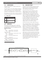
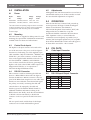
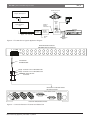
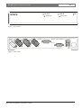
LTC 8781 Series
Instruction Manual
EN Time/Date
Converter Units
LTC 8781 | Instruction Manual | Important Safeguards
EN | 2
Important Safeguards
1. Read, Follow, and Retain Instructions - All safety
and operating instructions should be read and
followed before operating the unit. Retain instructions
for future reference.
2. Heed Warnings - Adhere to all warnings on the unit
and in the operating instructions.
3. Attachments - Attachments not recommended by the
product manufacturer should not be used, as they
may cause hazards.
4. Installation Cautions - Do not place this unit on an
unstable stand, tripod, bracket, or mount. The unit
may fall, causing serious injury to a person and
serious damage to the unit. Use only manufacturerrecommended accessories, or those sold with the
product. Mount the unit per the manufacturer's
instructions. Appliance and cart combination should
be moved with care. Quick stops, excessive force, or
uneven surfaces may cause the appliance and cart
combination to overturn.
5. Cleaning - Unplug the unit from the outlet before
cleaning. Follow any instructions provided with the
unit. Generally, using a damp cloth for cleaning is
sufficient. Do not use liquid cleaners or aerosol
cleaners.
6. Servicing - Do not attempt to service this unit
yourself. Opening or removing covers may expose
you to dangerous voltage or other hazards. Refer all
servicing to qualified service personnel.
7. Damage Requiring Service - Unplug the unit from
the main AC power source and refer servicing to
qualified service personnel under the following
conditions:
• When the power supply cord or plug is damaged.
• If liquid has been spilled or an object has fallen
into the unit.
• If the unit has been exposed to water and/or
inclement weather (rain, snow, etc.).
• If the unit does not operate normally, when
following the operating instructions. Adjust only
those controls specified in the operating
instructions. Improper adjustment of other controls
may result in damage, and require extensive work
by a qualified technician to restore the unit to
normal operation.
• If the unit has been dropped or the cabinet
damaged.
• If the unit exhibits a distinct change in
performance, this indicates that service is needed.
8. Replacement Parts - When replacement parts are
required, the service technician should use
replacement parts specified by the manufacturer or
that have the same characteristics as the original part.
Unauthorized substitutions may result in fire,
electrical shock or other hazards.
9. Safety Check - Upon completion of servicing or
repairs to the unit, ask the service technician to
perform safety checks to ensure proper operating
condition.
Bosch Security Systems | November 17, 2004
10. Power Sources - Operate the unit only from the type
of power source indicated on the label. If unsure of
the type of power supply to use, contact your dealer
or local power company.
• For units intended to operate from battery power,
refer to the operating instructions.
• For units intended to operate with External Power
Supplies, use only the recommended approved
power supplies.
• For units intended to operate with a limited power
source, this power source must comply with
EN60950. Substitutions may damage the unit or
cause fire or shock.
• For units intended to operate at 24 VAC, normal
input voltage is 24 VAC. Voltage applied to the
unit's power input should not exceed 30 VAC.
User-supplied wiring, from the 24 VAC supply to
unit, must be in compliance with electrical codes
(Class 2 power levels). Do not ground the 24 VAC
supply at the terminals or at the unit's power
supply terminals.
11. Coax Grounding - If an outside cable system is
connected to the unit, ensure that the cable system is
grounded. U.S.A. models only - Section 810 of the
National Electrical Code, ANSI/NFPA No.70,
provides information regarding proper grounding of
the mount and supporting structure, grounding of the
coax to a discharge unit, size of grounding
conductors, location of discharge unit, connection to
grounding electrodes, and requirements for the
grounding electrode.
12. Grounding or Polarization - This unit may be
equipped with a polarized alternating current line
plug (a plug with one blade wider than the other).
This safety feature allows the plug to fit into the
power outlet in only one way. If unable to insert the
plug fully into the outlet, try reversing the plug. If the
plug still fails to fit, contact an electrician to arrange
replacement of the obsolete outlet. Do not defeat the
safety purpose of the polarized plug.
Alternately, this unit may be equipped with a
3-wire grounding plug (a plug with a third pin, for
grounding). This safety feature allows the plug to fit
into a grounding power outlet only. If unable to insert
the plug into the outlet, contact an electrician to
arrange replacement of the obsolete outlet. Do not
defeat the safety purpose of the grounding plug.
13. Lightning - For added protection during a lightning
storm, or when this unit is left unattended and unused
for long periods of time, unplug the unit from the
wall outlet and disconnect the cable system. This will
prevent damage to the unit due to lightning and
power line surges.
EN | 3
LTC 8781 | Instruction Manual | FCC Information
For Indoor Product
1. Water and Moisture - Do not use this unit near
water - for example, in a wet basement, in an
unprotected outdoor installation or in any area
classified as a wet location.
2. Object and Liquid Entry - Never push objects of
any kind into this unit through openings, as they
may touch dangerous voltage points or short out
parts that could result in a fire or electrical shock.
Never spill liquid of any kind on the unit.
3. Power Cord and Power Cord Protection - For
units intended to operate with 230 VAC, 50 Hz,
the input and output power cord must comply
with the latest versions of IEC Publication 227 or
IEC Publication 245.
Power supply cords should be routed so they are
not likely to be walked on or pinched. Pay
particular attention to location of cords and plugs,
convenience receptacles, and the point of exit
from the appliance.
4. Overloading - Do not overload outlets and
extension cords; this can result in a risk of fire or
electrical shock.
For Outdoor Product
Power Lines - An outdoor system should not be
located in the vicinity of overhead power lines,
electric lights or power circuits, or where it may
contact such power lines or circuits. When
installing an outdoor system, extreme care should
be taken to keep from touching power lines or
circuits, as this contact might be fatal. U.S.A.
models only - refer to the National Electrical
Code Article 820 regarding installation of CATV
systems.
For Rack-mount Product
1. Ventilation - This unit should not be placed in a
built-in installation or rack, unless proper
ventilation is provided, or the manufacturer’s
instructions have been adhered to. The
equipment must not exceed its maximum
operating temperature requirements.
2. Mechanical Loading - Mounting of the
equipment in a rack shall be such that a
hazardous condition is not achieved due to
uneven mechanical loading.
Bosch Security Systems | November 17, 2004
ATTENTION
OBSERVE PRECAUTIONS
FOR HANDLING
ELECTROSTATIC SENSITIVE
DEVICES
WARNING:
Electrostatic-sensitive device. Use
proper CMOS/MOSFET handling
precautions to avoid electrostatic
discharge.
NOTE: Grounded wrist straps must be worn and proper ESD
safety precautions observed when handling the electrostaticsensitive printed circuit boards.
FCC & ICES INFORMATION
(U.S.A. and Canadian Models Only)
This device complies with part 15 of the FCC Rules. Operation is
subject to the following two conditions:
(1)
This device may not cause harmful interference, and
(2)
This device must accept any interference received,
including interference that may cause undesired
operation.
NOTE: This equipment has been tested and found to comply
with the limits for a Class B digital device, pursuant to Part 15 of
the FCC Rules and ICES-003 of Industry Canada. These limits
are designed to provide reasonable protection against harmful
interference when the equipment is operated in a residential
installation. This equipment generates, uses and can radiate radio
frequency energy, and if not installed and used in accordance
with the instructions, may cause harmful interference to radio
communications. However, there is no guarantee that interference
will not occur in a particular installation. If this equipment does
cause harmful interference to radio or television reception, which
can be determined by turning the equipment off and on, the user
is encouraged to try to correct the interference by one or
more of the following measures:
• Reorient or relocate the receiving antenna.
• Increase the separation between the equipment and receiver.
• Connect the equipment into an outlet on a circuit different
from that to which the receiver is connected.
• Consult the dealer, or an experienced radio/TV technician for
help.
Intentional or unintentional changes or modifications, not
expressly approved by the party responsible for compliance, shall
not be made. Any such changes or modifications could void the
user’s authority to operate the equipment.The user may find the
following booklet, prepared by the Federal Communications
Commission, helpful: How to Identify and Resolve Radio-TV
Interference Problems. This booklet is available from the U.S.
Government Printing Office, Washington, DC 20402, Stock No.
004-000-00345-4.
EN | 4
LTC 8781 | Instruction Manual | Safety Precautions
Safety Precautions
CAUTION: TO REDUCE THE RISK OF
ELECTRIC SHOCK, DO NOT REMOVE COVER
(OR BACK). NO USER SERVICEABLE PARTS
INSIDE. REFER SERVICING TO QUALIFIED
SERVICE PERSONNEL.
This symbol indicates the presence of
uninsulated “dangerous voltage” within the
product’s enclosure. This may constitute a
risk of electric shock.
Sécurité
ATTENTION : POUR ÉVITER TOUT RISQUE D'ÉLECTROCUTION,
N'ESSAYEZ PAS DE RETIRER LE CAPOT (OU LE PANNEAU
ARRIÈRE). CET APPAREIL NE CONTIENT AUCUN COMPOSANT
SUSCEPTIBLE D'ÊTRE RÉPARÉ PAR L'UTILISATEUR. CONFIEZ
LA RÉPARATION DE L'APPAREIL À DU PERSONNEL QUALIFIÉ.
Ce symbole signale que le produit renferme une « tension
potentiellement dangereuse » non isolée susceptible de
provoquer une électrocution.
Ce symbole invite l'utilisateur à consulter les instructions
d'utilisation et d'entretien (dépannage) reprises dans la
documentation qui accompagne l'appareil.
The user should consult the operating and
maintenance (servicing) instructions in the
literature accompanying the appliance.
Attention : l'installation doit exclusivement être réalisée par du
personnel qualifié, conformément au code national d'électricité
américain (NEC) ou au code d'électricité local en vigueur.
Attention: Installation should be performed by
qualified service personnel only in accordance
with the National Electrical Code or applicable
local codes.
Coupure de l'alimentation. Qu'ils soient pourvus ou non d'un
commutateur ON/OFF, tous les appareils reçoivent de l'énergie une
fois le cordon branché sur la source d'alimentation. Toutefois,
l'appareil ne fonctionne réellement que lorsque
le commutateur est réglé sur ON. Le débranchement du cordon
d'alimentation permet de couper l'alimentation des appareils.
Power Disconnect. Units with or without
ON-OFF switches have power supplied to the
unit whenever the power cord is inserted into the
power source; however, the unit is operational
only when the ON-OFF switch is in the ON
position. The power cord is the main power
disconnect for all units.
Bosch Security Systems | November 17, 2004
LTC 8781 | Instruction Manual | Contents
EN | 5
Table of Contents
Important Safeguards . . . . . . . . . . . . . . . . . . . . . . . . . . . . . . . . . . . . . . . . . . . . . . . . . . . . . . . . . . . . . . . . . .2
FCC Information . . . . . . . . . . . . . . . . . . . . . . . . . . . . . . . . . . . . . . . . . . . . . . . . . . . . . . . . . . . . . . . . . . . . .3
1.0
UNPACKING . . . . . . . . . . . . . . . . . . . . . . . . . . . . . . . . . . . . . . . . . . . . . . . . . . . . . . . . . . . . . . . . . .6
1.1
Parts List . . . . . . . . . . . . . . . . . . . . . . . . . . . . . . . . . . . . . . . . . . . . . . . . . . . . . . . . . . . . . . . . . . . . . .6
2.0
SERVICE . . . . . . . . . . . . . . . . . . . . . . . . . . . . . . . . . . . . . . . . . . . . . . . . . . . . . . . . . . . . . . . . . . . . .6
3.0
DESCRIPTION . . . . . . . . . . . . . . . . . . . . . . . . . . . . . . . . . . . . . . . . . . . . . . . . . . . . . . . . . . . . . . . .6
4.0
INSTALLATION . . . . . . . . . . . . . . . . . . . . . . . . . . . . . . . . . . . . . . . . . . . . . . . . . . . . . . . . . . . . . . .7
4.1
Power . . . . . . . . . . . . . . . . . . . . . . . . . . . . . . . . . . . . . . . . . . . . . . . . . . . . . . . . . . . . . . . . . . . . . . . . .7
4.2
Mounting . . . . . . . . . . . . . . . . . . . . . . . . . . . . . . . . . . . . . . . . . . . . . . . . . . . . . . . . . . . . . . . . . . . . . .7
4.3
Control Code Inputs . . . . . . . . . . . . . . . . . . . . . . . . . . . . . . . . . . . . . . . . . . . . . . . . . . . . . . . . . . . . .7
4.4
RS-232 Connector . . . . . . . . . . . . . . . . . . . . . . . . . . . . . . . . . . . . . . . . . . . . . . . . . . . . . . . . . . . . . . .7
4.5
Adjustments . . . . . . . . . . . . . . . . . . . . . . . . . . . . . . . . . . . . . . . . . . . . . . . . . . . . . . . . . . . . . . . . . . . .7
5.0
OPERATION . . . . . . . . . . . . . . . . . . . . . . . . . . . . . . . . . . . . . . . . . . . . . . . . . . . . . . . . . . . . . . . . . .7
6.0
PIN OUTS . . . . . . . . . . . . . . . . . . . . . . . . . . . . . . . . . . . . . . . . . . . . . . . . . . . . . . . . . . . . . . . . . . . .7
6.1
Code Input Connector . . . . . . . . . . . . . . . . . . . . . . . . . . . . . . . . . . . . . . . . . . . . . . . . . . . . . . . . . . . .7
6.2
RS-232 Input/Output Connector . . . . . . . . . . . . . . . . . . . . . . . . . . . . . . . . . . . . . . . . . . . . . . . . . . .7
Bosch Security Systems | November 17, 2004
EN | 6
LTC 8781 | Instruction Manual | Unpacking
1.0
UNPACKING
3.0
This electronic equipment should be unpacked and
handled carefully.
If an item appears to have been damaged in shipment,
replace it properly in its carton and notify the shipper.
If any items are missing, notify your Bosch Security
Systems Inc. Sales Representative or Customer Service.
The shipping carton is the safest container in which the
unit may be transported. Save it for possible future use.
1.1
Parts List
Qty
Item
1
One (1) cable with 15-pin
connectors at one end
1
One (1) RS-232 to RS-422
converter
2.0
SERVICE
If the unit ever needs repair service, contact the
nearest Bosch Security Systems Inc. Service Center
for authorization to return and shipping instructions
Service Centers
USA
Phone:
800-366-2283 or 717-735-6638
Fax:
800-366-1329 or 717-735-6639
CCTV Spare Parts
Phone:
800-894-5215 or 408-956-3853 or 3854
Fax:
408-957-3198
E-mail:
[email protected]
Canada
Phone:
514-738-2434
Europe, Middle East & Asia Pacific Region
Phone:
32-1-440-0711
For additional information, see
www.boschsecuritysystems.com.
DESCRIPTION
The LTC 8781 Series Time/Date Converter units are
designed to operate with Allegiant® Series Video
Matrix Switcher/Controllers, and Kalatel KTS-53
Series Time/Date/Title Generators.
The LTC 8781 Series unit is designed to receive
Allegiant biphase control code, and decode the
time/date information contained within it. This
time/date data is then converted by the LTC 8781
Series into NMEA style $GPZDA time/date format,
which is recognized by the Kalatel KTS-53 Series units.
A simple Allegiant Time Event is used to determine
how often an Allegiant CPU will generate the
time/date information in its biphase control code
output. The Time Event is programmed using the
Allegiant Master Control Software package.
The LTC 8781 Series provides an RS-232 interface
using one RS-232 interface connector. The interface
connector labeled RS-232 provides a standard RS-232
interface for connection to an external RS-232 to
RS-422 converter. The data rate of this RS-232
interface is 4800 baud, in compliance with NMEA
standard 0183 v. 2.0. This standard is used by most
global positioning system receivers. The CONSOLE
interface is not used, and should not be connected.
LED indicators on the front panel show RS-232 data
being transmitted (RS-232 OUT), biphase data being
received (CODE IN), and power ON. The LED
indicators labeled RS-232 IN and CODE OUT are not
used (and will not be illuminated). See Figure 4. A
conceptual block diagram is shown in Figure 1 for
reference purposes.
LTC 8781 Series Time/Date Converter Unit
Biphase Code In
Biphase
Decoder
Biphase
Filter
Time/Date
Format
Converter
RS-232
Transmitter
Figure 1: LTC 8781 Series Conceptional Operational Block Diagram
Bosch Security Systems | November 17, 2004
RS-232
Output
RS-232 to
RS-422 Converter
RS-422 Output
EN | 7
LTC 8781 | Instruction Manual | Installation
4.0
INSTALLATION
4.5
4.1
Power
Although the LTC 8781 Series units have several sets of
internal DIP switches, none of these switches are used.
No user-selectable adjustments are required.
Model
Rated
Voltage
Nominal
Voltage
Range
Power2
LTC 8781/60
120 VAC, 50/60 Hz
105 to 130
4W
LTC 8781/50
230 VAC, 50/60 Hz
195.5 to 253 4 W
No.
1
1
The model number and operating voltage are shown on the label
located on the bottom of the unit. These units are supplied with
grounded power cords. Grounding must not be defeated.
2
At rated voltage.
4.2
Mounting
LTC 8781 Series are supplied as desktop units. For rack
mounting, the optional LTC 9101/00 Rack-mount Kit is
available. LTC 8781 Series are half-rack units.
4.3
OPERATION
After the unit has been connected and powered up,
normal operation will begin. Consult the Allegiant
Master Control Software User Manual or
LTC 8850/00 Graphical Users Interface (GUI) with
Allegiant Server User Manual to set up the
Synchronize Satellite command in the Time Event
table. Optimum accuracy is assured when the
command is sent as frequently as possible (every 5
minutes), but less frequent updates may be acceptable.
Note that the Kalatel KTS-53 Series unit will appear to
be about half a second fast -- this is normal.
Control Code Inputs
The biphase code input connector is located on the
rear of the unit, next to the power cord. See Figure 5.
Connection is made using one of the supplied 15-pin
cable assemblies. Only the CODE IN -, SHIELD, and
CODE IN + pins of this connector are used. Other
wires on the supplied cable should be removed or cut
off. The CODE IN -, SHIELD, and CODE IN +
wires are then connected to the device generating the
biphase code (such as the CODE or SDA output of an
Allegiant main CPU bay or an output from a
LTC 8568/00 Signal Distribution unit).
4.4
5.0
Adjustments
6.0
PIN OUTS
6.1
Code Input Connector
Pin
Connection
Pin
Connection
1
Code In -
9
No Connect
2
No Connect
10
No Connect
3
No Connect
11
Code In +
4
No Connect
12
No Connect
5
No Connect
13
No Connect
6
Shield
14
No Connect
7
No Connect
15
No Connect
8
No Connect
RS-232 Connector
This connector is used for interfacing the LTC 8781
Series to a Kalatel KTS-53 Series unit. See Figure 5.
Connect the RS-232 to RS-422 converter to the rear
panel of the Kalatel unit using the two-wire cable. Note
that the two-wire cable that carries the RS-422 signal
has polarity; incorrectly connecting this cable will
cause the data to be improperly decoded, and
therefore, ignored. Consult the Kalatel manual for
additional installation information relating to the
KTS-53 Series unit. Finally, attach the external RS-232
to RS-422 converter unit directly to the RS-232
connector on the rear panel of the LTC 8781 Series
unit.
The rear panel console and the three Code Output
connectors are not used and should be ignored.
Bosch Security Systems | November 17, 2004
6.2
RS-232 Input/Output Connector
Pin
Connection
Pin
Connection
1
No Connect
6
No Connect
2
RXD
7
RTS
3
TXD
8
CTS
4
DTR
9
No Connect
5
Ground
EN | 8
LTC 8781 | Instruction Manual | Pin Outs
AutoDome System
Camera 1
Allegiant Matrix System
OR
LTC 8568 Series
Signal Distribution
Unit
Shielded
Twisted
Pair Cable
Additional
Video
Inputs
Camera
DVR/VCR
Biphase
Signal
LTC 8781
Time/Date
Converter
RS-232 to
RS-422
Converter
GPS
Time/Date
Generator
Code In
RS-232
Port
Additional Video
Outputs
Figure 2: LTC 8781 Series Typical Application Diagram
GPS Time/Date Generator
(KALATEL KTS-53-16 Shown)
9 VAC
OUT 12 VDC VIDEO
IN
A B A B A B
IN
VIDEO
OUT
Twisted Pair
Shielded Cable
TD(A) - Connect to "B" of Time/Date Unit
TD(A)
TD(B)
RD(A)
RD(B)
GND
+12V
TD(B) - Connect to "A" of Time/Date Unit
RS-232 to RS-422
Converter
Connection to LTC 8781 Series
RS-232 Connector
CODE
OUTPUT
15
CONSOLE
CODE IN- SHIELD CODE IN+
5
10 4
9 3
14 8 2
13 7 1
12 6
11
RS-232
LTC 8781 Time/Date Converter
Figure 3: Connection Between LTC 8781 and Kalatel Unit
Bosch Security Systems | November 17, 2004
EN | 9
LTC 8781 | Instruction Manual | Pin Outs
CODE IN
RS-232 IN
BOSCH
CODE OUT
RS-232 OUT
Figure 4: Front Panel
CODE
OUTPUT
15
5
10 4
9 3
14 8 2
13 7 1
12 6
11
Figure 5: Rear Panel
Bosch Security Systems | November 17, 2004
CODE IN- SHIELD CODE IN+
CONSOLE
RS-232
ON
LTC 8781 | Instruction Manual |
Bosch Security Systems | November 17, 2004
EN | 10
LTC 8781 | Instruction Manual |
Bosch Security Systems | November 17, 2004
EN | 11
Americas
Bosch Security Systems
130 Perinton Parkway
Fairport, New York, 14450, USA
Phone: +1 (585) 223 4060
Fax:
+1 (585) 223 9180
E-mail:
[email protected]
www.boschsecurity.us
Europe, Middle East, Africa
Bosch Security Systems B.V.
P.O. Box 80002
5600 JB Eindhoven, The Netherlands
E-mail:
[email protected]
http://www.boschsecurity.com
Asia-Pacific
Bosch Security Systems Pte Ltd
38C Jalan Pemimpin
Singapore 577180, Singapore
Phone: +65 319 3488
Fax:
+65 319 3499
E-mail:
[email protected]
http://www.boschsecurity.com
© 2004 Bosch Security Systems GmbH
3935 890 04312 04-47 | Updated November 17, 2004 | Data subject to change without notice.