1
SMART-MR10/15™
User Manual
OM-20000130 Rev 4
SMART-MR10/15 User Manual
Publication Number:
Revision Level:
Revision Date:
Firmware Version:
OM-20000130
4
2011/03/11
SMART-MR10: OEMV 3.802, SmartAgApp 1.200
SMART-MR15: OEMV 3.804, SmartAgApp 1.300
Proprietary Notice
Proprietary Notice
Information in this document is subject to change without notice and does not represent a commitment
on the part of NovAtel Inc. The software described in this document is furnished under a licence
agreement or non-disclosure agreement. The software may be used or copied only in accordance with
the terms of the agreement. It is against the law to copy the software on any medium except as
specifically allowed in the license or non-disclosure agreement.
No part of this manual may be reproduced or transmitted in any form or by any means, electronic or
mechanical, including photocopying and recording, for any purpose without the express written
permission of a duly authorized representative of NovAtel Inc.
The information contained within this manual is believed to be true and correct at the time of
publication.
ALIGN, GL1DE, NovAtel, OEMV, and RT-20 are registered trademarks of NovAtel Inc.
OEMV-3, RT-2, SMART-MR10, SMART-MR15 and SPAN are trademarks of NovAtel Inc.
The Bluetooth® word mark and logos are registered trademarks owned by Bluetooth SIG, Inc. and
any use of such marks by NovAtel Inc. is under license. All other brand names are trademarks of their
respective holders.
Manufactured and protected under U.S. Patents:
#5,101,416
#5,390,207
#5,414,729
#5,495,499
#5,734,674
#5,736,961
#5,809,064
#6,184,822 B1
#6,243,409 B1
#6,445,354 B1
#6,452,560 B2
#6,466,177 B1
#6,608,998 B1
#6,664,923 B1
#6,728,637 B2
#7,250,916
#7,738,536
#7,738,606
© Copyright 2010-2011 NovAtel Inc. All rights reserved. Unpublished rights
reserved under International copyright laws. Printed in Canada on recycled paper.
Recyclable.
2
SMART-MR10/15 User Manual Rev 4
Table of Contents
Proprietary Notice
Notices
Terms and Conditions
Software License
Warranty
Foreword
Customer Support
Firmware Updates and Model Upgrades
1 Introduction
2
8
12
14
17
18
20
21
22
1.1 Features................................................................................................................ 22
1.1.1 SMART-MR10 ............................................................................................. 22
1.1.2 SMART-MR15 ............................................................................................. 23
1.2 Box Contents ........................................................................................................ 23
1.2.1 SMART-MR10 ............................................................................................. 23
1.2.2 SMART-MR15 ............................................................................................. 23
1.3 Accessories........................................................................................................... 24
1.3.1 SMART-MR15-Specific Accessories ........................................................... 24
1.4 Models .................................................................................................................. 25
1.4.1 SMART-MR10 ............................................................................................. 25
1.4.2 SMART-MR15 ............................................................................................. 26
1.5 Installing the PC Utilities ....................................................................................... 26
2 Installation
27
2.1 Additional Equipment Required ............................................................................ 27
2.1.1 Mounting Kits............................................................................................... 27
2.2 Mounting the SMART-MR10/15............................................................................ 32
2.3 Cabling the SMART-MR10/15 .............................................................................. 32
2.3.1 Connecting the Power Supply ..................................................................... 36
2.3.2 Status Indicators.......................................................................................... 37
2.3.3 Debugging Guidelines: ................................................................................ 39
2.3.4 Connecting Data Communications Equipment............................................ 40
2.4 Additional Installation Information ......................................................................... 40
2.4.1 MKI and PPS Strobes.................................................................................. 40
2.4.2 Emulated Radar (ER) .................................................................................. 40
2.4.3 Controller Area Network (CAN) ................................................................... 41
2.4.4 SMART-MR15 CELLULAR ANTENNA INSTALLATION............................. 41
2.4.5 SMART-MR15 - Installation Details for Cellular Activation.......................... 43
3 Operation
46
3.1 Communications with the Receiver....................................................................... 46
3.1.1 Serial Port Default Settings ......................................................................... 46
3.1.2 Communicating Using a Remote Terminal.................................................. 47
3.1.3 Communicating Using a Personal Computer .............................................. 47
SMART-MR10/15 User Manual Rev 4
3
Table of Contents
3.2 Getting Started ..................................................................................................... 47
3.2.1 Starting the Receiver .................................................................................. 47
3.2.2 Communicating with the Receiver Using CDU ........................................... 48
3.3 Transmitting and Receiving Corrections............................................................... 49
3.3.1 Base Station Configuration ......................................................................... 51
3.3.2 Rover Station Configuration........................................................................ 52
3.3.3 GPS + GLONASS Base and Rover Configuration...................................... 53
3.3.4 Configuration Notes .................................................................................... 54
3.3.5 SBAS (Satellite-Based Augmentation Systems)......................................... 55
3.4 GL1DE® ............................................................................................................... 56
3.5 ALIGN® ................................................................................................................ 56
3.5.1 ALIGN Heading Master and Remote Configurations .................................. 56
3.6 Emulated Radar (ER) ........................................................................................... 57
3.7 NTRIP Client ........................................................................................................ 57
3.8 Recommended Configuration............................................................................... 58
4 PC Utilities
59
4.1 CDU/Convert4 Installation .................................................................................... 59
4.2 CDU...................................................................................................................... 60
4.3 Convert4 ............................................................................................................... 65
4.3.1 RINEX Format............................................................................................. 65
4.3.2 Convert4 Command Line Switches............................................................. 67
4.4 Firmware Updates and Model Upgrades.............................................................. 68
4.4.1 Updating or Upgrading Using the WinLoad Utility....................................... 68
4.4.2 Upgrading Using the AUTH Command....................................................... 72
5 Bluetooth® Configuration
74
5.1 Enable Bluetooth on the Receiver ........................................................................ 74
5.2 Set Up a PC/Laptop with a Bluetooth Adaptor ..................................................... 76
5.3 Locate a Bluetooth-Enabled SMART-MR10 or SMART-MR15 in Range............. 76
5.4 Communicate with the SMART-MR10 or SMART-MR15 Using Bluetooth........... 77
5.5 Stop Communicating with SMART-MR10 or SMART-MR15 Using Bluetooth ..... 79
A Technical Specifications
80
SMART-MR10/15 Receiver Performance ................................................................. 80
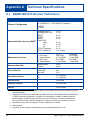
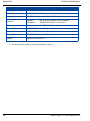
SMART-MR10 Specifications .................................................................................... 81
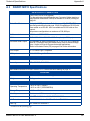
SMART-MR15 Specifications .................................................................................... 85
Connector Cables ...................................................................................................... 89
Evaluation Cable (Part Number 01018515) ........................................................ 89
Streamlined Cable (Part Number 01018526) ...................................................... 91
Custom Connector and Cable Requirements ..................................................... 93
B Commands
94
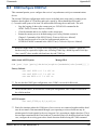
Syntax Conventions .................................................................................................. 94
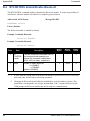
BTCONTROL Enable/Disable Bluetooth ................................................................... 96
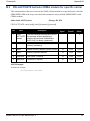
CELLACTIVATE Activate CDMA modem for specific carrier .................................... 97
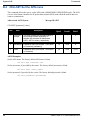
CELLSET Set the APN name .................................................................................... 98
COM Configure COM Port ........................................................................................ 99
FRESET Clear Selected Data from NVM and Reset ............................................... 102
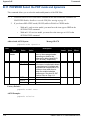
LOG Request Logs from the Receiver .................................................................... 103
4
SMART-MR10/15 User Manual Rev 4
Table of Contents
NTRIPCASTER Set NTRIP caster ........................................................................... 108
NTRIPCLIENT Mount or unmount NTRIP client ...................................................... 109
PDPFILTER Enable, disable or reset the PDP filter ................................................ 111
PDPMODE Select the PDP mode and dynamics .................................................... 112
RADARCFG Configure the ER output ..................................................................... 113
RESET Performs a hardware reset ......................................................................... 115
SBASCONTROL Set SBAS test mode and PRN .................................................... 116
C Logs
118
NMEA Logs .............................................................................................................. 118
NovAtel Position Logs .............................................................................................. 120
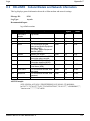
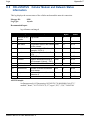
CELLINFO Cellular Modem and Network Information .......................................... 121
CELLSOCKETSTATUS Modem Call Status Information ...................................... 122
CELLSTATUS Cellular Modem and Network Status Information .......................... 123
NTRIPSOURCETABLE Source Table Records from Current Caster ................... 124
NTRIPSTATUS Status of NTRIP Connection ....................................................... 125
RADARSIGNAL ER Signal and Position Information ............................................ 128
VERSION HW & SW Versions and Serial Numbers ............................................. 131
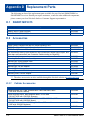
D Replacement Parts
132
SMART-MR10/15 ..................................................................................................... 132
Accessories .............................................................................................................. 132
Cellular Accessories .......................................................................................... 132
Index
SMART-MR10/15 User Manual Rev 4
133
5
Figures
1
2
3
4
5
6
7
8
9
10
11
12
13
14
15
16
17
18
19
20
21
22
23
24
25
26
27
28
29
30
31
32
33
34
35
36
37
6
SMART-MR10 Receiver ................................................................................................... 25
SMART-MR15 Receiver ................................................................................................... 26
SMART-MR10/15 Mounting Kit, Quick Release Plate (01018625) .................................. 28
SMART-MR10/15 Mounting Kit, Quick Release Assembly (01018578) .......................... 29
SMART-MR10/15 Mounting Kit, AG GPS 262 (01018623) .............................................. 30
SMART-MR10/15 Mounting Kit, 5/8 Inch Adapter (01018624) ........................................ 31
SMART-MR10/15 Connector ........................................................................................... 32
SMART-MR10/15 Cabling ................................................................................................ 33
Cellular Antenna Placement ............................................................................................. 42
SIM Cover ........................................................................................................................ 44
SIM Being Installed .......................................................................................................... 44
SIM Correctly Installed ..................................................................................................... 44
SIM Ready for Removal ................................................................................................... 44
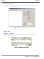
Open Configuration Window ............................................................................................ 48
Basic Differential Setup .................................................................................................... 50
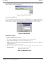
NTRIP Client Configuration .............................................................................................. 57
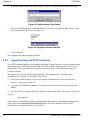
Convert4 Screen Examples ............................................................................................. 65
Convert4 Command Line Arguments ............................................................................... 67
Main Screen of WinLoad .................................................................................................. 70
WinLoad’s Open Dialog ................................................................................................... 70
Open File in WinLoad ....................................................................................................... 71
COM Port Setup ............................................................................................................... 71
Searching for Card ........................................................................................................... 71
Authorization Code Dialog ............................................................................................... 72
Upgrade Process Complete ............................................................................................. 72
Bluetooth Configuration (SMART-MR10) ......................................................................... 74
Bluetooth Configuration (SMART-MR15) ......................................................................... 75
Bluetooth Adapter for PC/Laptop ..................................................................................... 76
Bluetooth Standby: White ................................................................................................. 76
Bluetooth Error: Red ........................................................................................................ 76
My Bluetooth Places Window ........................................................................................... 77
Bluetooth PIN Code Request ........................................................................................... 78
PC/Laptop COM3 Port Assignment ................................................................................. 78
Bluetooth Connected: Green ............................................................................................ 78
COM3 Disconnect? .......................................................................................................... 79
SMART-MR10/15 Evaluation Cable ................................................................................. 89
SMART-MR10/15 Streamlined Cable .............................................................................. 91
SMART-MR10/15 User Manual Rev 4
Tables
1
2
3
4
5
6
7
8
9
10
11
12
13
14
15
16
17
18
19
20
21
22
23
24
25
SMART-MR10 Controller Models............................................................................... 25
SMART-MR15 Controller Models............................................................................... 26
SMART-MR10 Connector Pin-Out ............................................................................. 34
SMART-MR10 Use of MODE Pin .............................................................................. 34
SMART-MR15 Connector Pin-Out ............................................................................. 35
SMART-MR15 Use of MODE Pin .............................................................................. 35
SMART-MR10 LED Status Indicators ........................................................................ 37
SMART-MR15 LED Behavior (NTRIP Client Active) ................................................. 38
Available CAN Signals on SMART-MR10/15 23-pin Tyco Connector ....................... 41
NovAtel Logs for RINEX Conversion ......................................................................... 66
Evaluation Cable Pinouts ........................................................................................... 90
Streamlined Cable Pinouts......................................................................................... 92
Mating Connectors ..................................................................................................... 93
Recommended Fuses ................................................................................................ 93
Commonly Used SMART-MR10/15 Commands in Alphabetical Order ..................... 94
COM Serial Port Identifiers ...................................................................................... 100
Parity ........................................................................................................................ 100
Handshaking ............................................................................................................ 100
FRESET Target........................................................................................................ 102
Detailed Serial Port Identifiers.................................................................................. 106
Response Modes ..................................................................................................... 114
Commonly Used SMART-MR10/-MR15 Logs in Alphabetical Order ....................... 118
Position or Velocity Type.......................................................................................... 129
Solution Status ......................................................................................................... 130
Component Type...................................................................................................... 131
SMART-MR10/15 User Manual Rev 4
7
Notices
Notices
The SMART-MR10 and SMART-MR15 are designed for and intended to be used in fixed and mobile
applications. "Fixed" means that the device is physically secured at one location and is not able to be
easily moved to another location. "Mobile" means that the device is designed to be used in other than
fixed locations. These products are not designed to be used as “Portable” devices in applications
where they would be closer than 20 cm (8 inches) to the user or any other personnel.
In the case of the SMART-MR15, it is important to follow any special regulations regarding the use of
radio equipment due in particular to the possibility of radio frequency (RF) interference. Please follow
the safety advice given below carefully.
The following notices apply, as appropriate, to the SMART-MR10 and SMART-MR15.
WARNING!
Changes or modifications to this equipment not expressly approved by
NovAtel Inc. could result in violation of FCC, Indusrty Canada and CE
Marking rules and void the user’s authorization to operate this equipment.
Safety
8
WARNING:
Personnel must be at least 20 cm (8 inches) from the SMART-MR15 cellular
antenna. The SMART-MR15 cellular antenna must be mounted such that personnel
are never closer than 20 cm (8 inches) to it. For antenna installations on non-metallic
vehicle cab roofs, users should exercise extra care that the 20 cm separation distance
between the antenna and personnel inside the vehicle will be maintained on the basis
of an imaginary line passing through the roof between the antenna and the body of
the operator or any passengers.
WARNING:
Switch OFF your SMART-MR10/15 when around gasoline or diesel-fuel pumps and
before filling your vehicle with fuel. Respect restrictions on the use of radio
equipment in fuel depots, chemical plants or where blasting operations are in
progress.
WARNING:
There may be a hazard associated with the operation of your SMART-MR10/15 close
to inadequately protected personal medical devices such as hearing aids and
pacemakers. Consult the manufacturers of the medical device to determine if it is
adequately protected.
SMART-MR10/15 User Manual Rev 4
Notice
WARNING:
Operation of your SMART-MR10/15 close to other electronic equipment may also
cause interference if the equipment is inadequately protected. Observe any warning
signs and manufacturers’ recommendations.
WARNING:
To comply with FCC and Industry Canada regulations limiting both maximum RF
output power and human exposure to RF radiation, the maximum system gain
(antenna gain minus system loss) must not exceed 1.4 dBi in the U.S. Cellular band
and 3.0 dBi in the PCS band for the GSM/GPRS/HSDPA variant, and 6.0 dBi in the
Cellular band and 6.0 dBi in the PCS band for the CDMA variant. System loss is the
total of external cable and connector losses and SMART-MR15 internal losses. For
reference and system gain calculation purposes, the SMART-MR15 has internal
losses of 0.6 dB for the 800 MHz Cellular band and 1.8 dB for the 1900 MHz PCS
band.
FCC
This device complies with part 15 of the FCC Rules. Operation is subject to the following two
conditions: (1) this device may not cause harmful interference, and (2) this device must accept any
interference received, including interference that may cause undesired operation.
SMART-MR10 and SMART-MR15 have been tested and found to comply with the emission limits for
a Class B digital device. The Class B limits are designed to provide reasonable protection against
harmful interference in a residential installation. SMART-MR10 and SMART-MR15 have been
certified by FCC for use in the 2400 MHz - 2483.5 MHz band (FCC ID # UTU01018518).
There are two versions of the SMART-MR15 - a CDMA version and a GSM/GPRS/HSDPA version.
The CDMA version (NovAtel part number 01018606) contains FCC ID # RI7CC864-DUAL and the
GSM/GPRS/HSDPA version (NovAtel part number 01018712) contains FCC ID # RI7UC864G.
This equipment generates, uses, and can radiate radio frequency energy and, if not installed and used
in accordance with the instructions, may cause harmful interference to radio communications.
However, there is no guarantee that interference will not occur in a particular installation. If this
equipment does cause harmful interference to radio or television reception, which can be determined
by turning the equipment off and on, the user is encouraged to try to correct the interference by one or
more of the following measures:
•
Re-orient or relocate the SMART-MR10/15
•
Increase the separation between the equipment and the SMART-MR10/15
•
Connect the equipment to an outlet on a circuit different from that to which the SMARTMR10/15 is connected
•
Consult the dealer or an experienced radio/TV technician for help
SMART-MR10/15 User Manual Rev 4
9
Notice
WARNING:
In order to maintain compliance as a Class “B” digital device, shielded cables must
be used for the RS-232 serial data ports (Belden 1036A or equivalent) and twisted
pair cable should be used for the CAN port (note: shielded twisted pair will also
improve CAN performance in electrically harsh environments). I/O signals should be
referred to one of the two signal grounds (connector pin 9 or connector pin 15) and
not power ground (connector pin 2). If I/O signals route to different areas of the
vehicle, dedicated signal grounds for I/O should be spliced into a common connection
to one of the two signal grounds (pin 9 or pin 15), at a point close to the SMARTMR10/15.
Industry Canada
SMART-MR10 and SMART-MR15 Class B digital apparatuses comply with Canadian ICES-003.
SMART-MR10 et SMART-MR15 appareils numérique de la classe B est conforme à la norme NMB003 du Canada.
CE Marking
SMART-MR10 and SMART-MR15 enclosures carry the CE mark.
“Hereby, NovAtel Inc. declares that the SMART-MR10 and SMART-MR15 comply with the essential
requirements and other relevant provisions of the R&TTE Directive 1999/5/EC and of the EMC
Directive 2004/108/EC.”
WEEE
If you purchased your OEMV® family product in Europe, please return it to your dealer or supplier at
the end of its life. The objectives of the European Community's environment policy are, in particular,
to preserve, protect and improve the quality of the environment, protect human health and utilise
natural resources prudently and rationally. Sustainable development advocates the reduction of
wasteful consumption of natural resources and the prevention of pollution. Waste electrical and
electronic equipment (WEEE) is regulated by the EU WEEE Directive 2002/96/EC and amendment
2003/108/EC. Where the generation of waste cannot be avoided, it should be reused or recovered for
its material or energy. WEEE products may be recognized by their wheeled bin label (
1.
10
). 1
Please visit the NovAtel website at www.novatel.com through Support | Products | WEEE and RoHS
for more information.
SMART-MR10/15 User Manual Rev 4
Notice
RoHS
The SMART-MR10 and SMART-MR15 comply with the European Union (EU) Restriction of
Hazardous Substances (RoHS) Directive 2002/95/EC.1
Bluetooth®
The SMART-MR10 and SMART-MR15 contain wireless technology using Bluetooth®. Bluetooth
QD (Qualified Design) ID B015463.
1.
Please visit the NovAtel website at www.novatel.com through Support | Products | WEEE and RoHS
for more information.
SMART-MR10/15 User Manual Rev 4
11
Terms and Conditions
Terms and Conditions
Standard Terms and Conditions of Sales
1. PRICES: All prices are Firm Fixed Price, FCA 1120 - 68th Avenue N.E., Calgary, Alberta. All
prices include standard commercial packing for domestic shipment. All transportation, insurance,
special packing costs and expenses, and all Federal, provincial and local excise, duties, sales, and
other similar taxes are the responsibility of the Purchaser.
2. PAYMENT: Terms are prepayment unless otherwise agreed in writing. Interest shall be charged
on overdue accounts at the rate of 18% per annum (1.5% per month) from due date. To expedite
payment by wire transfer to NovAtel Inc.: Bank - HSBC Bank of Canada
Bank:
HSBC Bank of Canada
US Account #
788889-002
407 - 8 Avenue S.W.
CDN Account #
788889-001
Calgary, AB, Canada T2P 1E5
EURO Account #
788889-270
Transit #
10029-016
Swift
HKBCCATTCAL
3. DELIVERY: Purchaser shall supply shipping instructions with each order. (Ship to and bill to
address, NovAtel Quotation #, Preferred carrier and account #, Custom broker/freight forwarder
including name and contact #) In the absence of specific instructions, NovAtel may select a carrier
and insure Products in transit and charge Purchaser accordingly. NovAtel shall not be responsible for
any failure to perform due to unforeseen circumstances or causes beyond its ability to reasonably
control. Risk of loss, damage or destruction shall pass to Purchaser upon delivery to carrier. Goods are
provided solely for incorporation into the Purchaser’s end product and shall not be onward delivered
except as incorporated in the Purchaser’s end product.
4. COPYRIGHT AND CONFIDENTIALITY: Copyright in any specification, drawing, computer
software, technical description and other document supplied by NovAtel under or in connection with
the Order and all intellectual property rights in the design of any part of the Equipment or provision of
services, whether such design be registered or not, shall vest in NovAtel absolutely. The Buyer shall
keep confidential any information expressed or confirmed by NovAtel in writing to be confidential
and shall not disclose it without NovAtel's prior consent in writing to any third party or use it other
than for the operation and maintenance of any Equipment provided.
5. GENERAL PROVISIONS: All Purchase Orders are subject to approval and acceptance by
NovAtel. Any Purchase Order or other form from the Purchaser, which purports to expand, alter or
amend these terms and conditions, is expressly rejected and is and shall not become a part of any
agreement between NovAtel and the Purchaser. This agreement shall be interpreted under the laws of
the Province of Alberta.
12
SMART-MR10/15 User Manual Rev 4
Terms and Conditions
6. LIMITED WARRANTY AND LIABILITY: Warranty Period: Products - 1 year; Accessories 90 days (in each case from the date of invoice). NovAtel warrants that during the Warranty Period that
(a) the Product will be free from defects in material and workmanship and conform to NovAtel
specifications; (b) the software will be free from error which materially affect performance; and (c) if
applicable as defined in the User’s Manual, be eligible for access to post contract support and software
updates when available. THESE WARRANTIES ARE EXPRESSLY IN LIEU OF ALL OTHER
WARRANTIES, EXPRESS OR IMPLIED, INCLUDING, WITHOUT LIMITATION, ALL
IMPLIED WARRANTIES OF MERCHANTABILITY AND FITNESS FOR A PARTICULAR
PURPOSE. NOVATEL SHALL IN NO EVENT BE LIABLE FOR SPECIAL, INDIRECT,
INCIDENTAL, OR CONSEQUENTIAL DAMAGES OF ANY KIND OR NATURE DUE TO
ANY CAUSE.
Purchaser’s exclusive remedy for a claim under this warranty shall be limited to the repair or
replacement at NovAtel’s option and at NovAtel’s facility, of defective or nonconforming materials,
parts or components or in the case of software, provision of a software revision for implementation by
the Buyer. All material returned under warranty shall be returned to NovAtel prepaid by the Buyer
and returned to the Buyer, prepaid by NovAtel. The foregoing warranties do not extend to (i)
nonconformities, defects or errors in the Products due to accident, abuse, misuse or negligent use of
the Products or use in other than a normal and customary manner, environmental conditions not
conforming to NovAtel’s specifications, or failure to follow prescribed installation, operating and
maintenance procedures, (ii) defects, errors or nonconformities in the Products due to modifications,
alterations, additions or changes not made in accordance with NovAtel’s specifications or authorized
by NovAtel, (iii) normal wear and tear, (iv) damage caused by force of nature or act of any third
person, (v) shipping damage, (vi) service or repair of Product by the Purchaser without prior written
consent from NovAtel, (vii) Products designated by NovAtel as beta site test samples, experimental,
developmental, preproduction, sample, incomplete or out of specification Products, (viii) returned
Products if the original identification marks have been removed or altered or (ix) Services or research
activities.
7. EXCLUSION OF LIABILITY: If a Party would, but for this paragraph (7), have concurrent
claims in contract and tort (including negligence) such claims in tort (including negligence) shall to
the extent permitted by law be wholly barred, unenforceable and excluded.
NovAtel shall not be liable to the Buyer by way of indemnity or by reason of any breach of the Order
or of statutory duty or by reason of tort (including but not limited to negligence) for any loss of profit,
loss of use, loss of production, loss of contracts or for any financing costs or for any indirect or
consequential damage whatsoever that may be suffered by the Buyer.
In the event and to the extent that NovAtel shall have any liability to Buyer pursuant to the terms of
the Order, NovAtel shall be liable to Buyer only for those damages which have been foreseen or might
have reasonably been foreseen on the date of effectivity of the Order and which are solely an
immediate and direct result of any act or omission of NovAtel in performing the work or any portion
thereof under the Order and which are not in the aggregate in excess of ten (10%) percent of the total
Order price.
SMART-MR10/15 User Manual Rev 4
13
Software License
Software License
BY INSTALLING, COPYING, OR OTHERWISE USING THE SOFTWARE PRODUCT, YOU
AGREE TO BE BOUND BY THE TERMS OF THIS AGREEMENT. IF YOU DO NOT
AGREE WITH THESE TERMS OF USE, DO NOT INSTALL, COPY OR USE THIS ELECTRONIC PRODUCT (SOFTWARE, FIRMWARE, SCRIPT FILES, OR OTHER ELECTRONIC PRODUCT WHETHER EMBEDDED IN THE HARDWARE, ON A CD OR
AVAILABLE ON THE COMPANY website) (hereinafter referred to as "Software").
1. License: NovAtel Inc. ("NovAtel") grants you a non-exclusive, non-transferable license (not a sale)
to, where the Software will be used on NovAtel supplied hardware or in conjunction with other
NovAtel supplied software, use the Software with the product(s) as supplied by NovAtel. You agree
not to use the Software for any purpose other than the due exercise of the rights and licences hereby
agreed to be granted to you.
2. Copyright: NovAtel owns, or has the right to sublicense, all copyright, trade secret, patent and
other proprietary rights in the Software and the Software is protected by national copyright laws,
international treaty provisions and all other applicable national laws. You must treat the Software like
any other copyrighted material except that you may make one copy of the Software solely for backup
or archival purposes (one copy may be made for each piece of NovAtel hardware on which it is
installed or where used in conjunction with other NovAtel supplied software), the media of said copy
shall bear labels showing all trademark and copyright notices that appear on the original copy. You
may not copy the product manual or written materials accompanying the Software. No right is conveyed by this Agreement for the use, directly, indirectly, by implication or otherwise by Licensee of
the name of NovAtel, or of any trade names or nomenclature used by NovAtel, or any other words or
combinations of words proprietary to NovAtel, in connection with this Agreement, without the prior
written consent of NovAtel.
3. Patent Infringement: NovAtel shall not be liable to indemnify the Licensee against any loss sustained by it as the result of any claim made or action brought by any third party for infringement of
any letters patent, registered design or like instrument of privilege by reason of the use or application
of the Software by the Licensee or any other information supplied or to be supplied to the Licensee
pursuant to the terms of this Agreement. NovAtel shall not be bound to take legal proceedings against
any third party in respect of any infringement of letters patent, registered design or like instrument of
privilege which may now or at any future time be owned by it. However, should NovAtel elect to take
such legal proceedings, at NovAtel's request, Licensee shall co-operate reasonably with NovAtel in all
legal actions concerning this license of the Software under this Agreement taken against any third
party by NovAtel to protect its rights in the Software. NovAtel shall bear all reasonable costs and
expenses incurred by Licensee in the course of co-operating with NovAtel in such legal action.
4. Restrictions: You may not:
(a)
copy (other than as provided for in paragraph 2), distribute, transfer, rent, lease, lend, sell or
sublicense all or any portion of the Software except in the case of sale of the hardware to a
third party;
(b)
modify or prepare derivative works of the Software;
(c)
use the Software in connection with computer-based services business or publicly display
14
SMART-MR10/15 User Manual Rev 4
Software License
visual output of the Software;
(d)
transmit the Software over a network, by telephone or electronically using any means (except
when downloading a purchased upgrade from the NovAtel website); or
(e)
reverse engineer, decompile or disassemble the Software.
You agree to keep confidential and use your best efforts to prevent and protect the contents of the Software from unauthorized disclosure or use.
5. Term and Termination: This Agreement and the rights and licences hereby granted shall continue
in force in perpetuity unless terminated by NovAtel or Licensee in accordance herewith. In the event
that the Licensee shall at any time during the term of this Agreement: i) be in breach of its obligations
hereunder where such breach is irremediable or if capable of remedy is not remedied within 30 days
of notice from NovAtel requiring its remedy; then and in any event NovAtel may forthwith by notice
in writing terminate this Agreement together with the rights and licences hereby granted by NovAtel.
Licensee may terminate this Agreement by providing written notice to NovAtel. Upon termination,
for any reasons, the Licensee shall promptly, on NovAtel's request, return to NovAtel or at the election
of NovAtel destroy all copies of any documents and extracts comprising or containing the Software.
The Licensee shall also erase any copies of the Software residing on Licensee's computer equipment.
Termination shall be without prejudice to the accrued rights of either party, including payments due to
NovAtel. This provision shall survive termination of this Agreement howsoever arising.
6. Warranty: NovAtel does not warrant the contents of the Software or that it will be error free. The
Software is furnished "AS IS" and without warranty as to the performance or results you may obtain
by using the Software. The entire risk as to the results and performance of the Software is assumed by
you. See product enclosure, if any for any additional warranty.
7. Indemnification: NovAtel shall be under no obligation or liability of any kind (in contract, tort or
otherwise and whether directly or indirectly or by way of indemnity contribution or otherwise howsoever) to the Licensee and the Licensee will indemnify and hold NovAtel harmless against all or any
loss, damage, actions, costs, claims, demands and other liabilities or any kind whatsoever (direct, consequential, special or otherwise) arising directly or indirectly out of or by reason of the use by the
Licensee of the Software whether the same shall arise in consequence of any such infringement, deficiency, inaccuracy, error or other defect therein and whether or not involving negligence on the part of
any person.
8. Disclaimer and Limitation of Liability:
(a)
THE WARRANTIES IN THIS AGREEMENT REPLACE ALL OTHER WARRANTIES, EXPRESS OR IMPLIED, INCLUDING ANY WARRANTIES OF MERCHANTABILITY OR FITNESS FOR A PARTICULAR PURPOSE. NovAtel
DISCLAIMS AND EXCLUDES ALL OTHER WARRANTIES. IN NO EVENT WILL
NovAtel's LIABILITY OF ANY KIND INCLUDE ANY SPECIAL, INCIDENTAL OR
CONSEQUENTIAL DAMAGES, INCLUDING LOST PROFITS, EVEN IF NovAtel
HAS KNOWLEDGE OF THE POTENTIAL LOSS OR DAMAGE.
(b)
NovAtel will not be liable for any loss or damage caused by delay in furnishing the Software
or any other performance under this Agreement.
(c)
NovAtel's entire liability and your exclusive remedies for our liability of any kind (including
liability for negligence) for the Software covered by this Agreement and all other performance or non-performance by NovAtel under or related to this Agreement are to the remedies specified by this Agreement.
SMART-MR10/15 User Manual Rev 4
15
Software License
9. Governing Law: This Agreement is governed by the laws of the Province of Alberta, Canada.
Each of the parties hereto irrevocably attorns to the jurisdiction of the courts of the Province of
Alberta.
10. Customer Support: For Software UPDATES and UPGRADES, and regular customer support,
contact the NovAtel GPS Hotline at 1-800-NOVATEL (U.S. or Canada only), or +1-403-295-4900,
Fax +1-403-295-4901, email to [email protected], website: http://www.novatel.com or write to:
NovAtel Inc.Customer Service Department
1120 - 68 Avenue NE
Calgary, Alberta, Canada T2E 8S5
16
SMART-MR10/15 User Manual Rev 4
Warranty
Warranty
NovAtel Inc. warrants that its products are free from defects in materials and workmanship, subject to
the conditions set forth below, for the following periods of time, from the date of sale:
SMART-MR10 and SMART-MR15
Antenna
Cables and Accessories
Computer Discs
Software Warranty
One (1) Year
One (1) Year
Ninety (90) Days
Ninety (90) Days
One (1) Year
Date of sale shall mean the date of the invoice to the original customer for the product. NovAtel’s
responsibility respecting this warranty is solely to product replacement or product repair at an
authorized NovAtel location, or in the case of software, provision of a software revision for
implementation by the customer.
Determination of replacement or repair will be made by NovAtel personnel or by technical personnel
expressly authorized by NovAtel for this purpose.
THE FOREGOING WARRANTIES DO NOT EXTEND TO (I) NONCONFORMITIES, DEFECTS OR ERRORS
IN THE PRODUCTS DUE TO ACCIDENT, ABUSE, MISUSE OR NEGLIGENT USE OF THE PRODUCTS OR
USE IN OTHER THAN A NORMAL AND CUSTOMARY MANNER, ENVIRONMENTAL CONDITIONS NOT
CONFORMING TO NOVATEL’S SPECIFICATIONS, OR FAILURE TO FOLLOW PRESCRIBED INSTALLATION, OPERATING AND MAINTENANCE PROCEDURES, (II) DEFECTS, ERRORS OR NONCONFORMITIES IN THE PRODUCTS DUE TO MODIFICATIONS, ALTERATIONS, ADDITIONS OR CHANGES NOT
MADE IN ACCORDANCE WITH NOVATEL’S SPECIFICATIONS OR AUTHORIZED BY NOVATEL, (III) NORMAL WEAR AND TEAR, (IV) DAMAGE CAUSED BY FORCE OF NATURE OR ACT OF ANY THIRD PERSON, (V) SHIPPING DAMAGE; OR (VI) SERVICE OR REPAIR OF PRODUCT BY THE DEALER WITHOUT
PRIOR WRITTEN CONSENT FROM NOVATEL. IN ADDITION, THE FOREGOING WARRANTIES SHALL
NOT APPLY TO PRODUCTS DESIGNATED BY NOVATEL AS BETA SITE TEST SAMPLES, EXPERIMENTAL,
DEVELOPMENTAL, PREPRODUCTION, SAMPLE, INCOMPLETE OR OUT OF SPECIFICATION PRODUCTS OR TO RETURNED PRODUCTS IF THE ORIGINAL IDENTIFICATION MARKS HAVE BEEN
REMOVED OR ALTERED. THE WARRANTIES AND REMEDIES ARE EXCLUSIVE AND ALL OTHER WARRANTIES, EXPRESS OR IMPLIED, WRITTEN OR ORAL, INCLUDING THE IMPLIED WARRANTIES OF
MERCHANTABILITY OR FITNESS FOR ANY PARTICULAR PURPOSE ARE EXCLUDED. NOVATEL SHALL
NOT BE LIABLE FOR ANY LOSS, DAMAGE, EXPENSE, OR INJURY ARISING DIRECTLY OR INDIRECTLY
OUT OF THE PURCHASE, INSTALLATION, OPERATION, USE OR LICENSING OR PRODUCTS OR SERVICES. IN NO EVENT SHALL NOVATEL BE LIABLE FOR SPECIAL, INDIRECT, INCIDENTAL OR CONSEQUENTIAL DAMAGES OF ANY KIND OR NATURE DUE TO ANY CAUSE.
There are no user serviceable parts in the NovAtel receiver and no maintenance is required. When the
status code indicates that a unit is faulty, replace with another unit and return the faulty unit to
NovAtel Inc.
Before shipping any material to NovAtel or Dealer, please contact Customer Support. You can
e-mail [email protected] or visit our website at www.novatel.com and log in through Support | Helpdesk & Solutions | E-Service.
When Customer Support confirms the faulty equipment needs to be returned, you will be referred to
the repair group where you will be given an RMA number and be advised of proper shipping
procedures to return any defective product.
SMART-MR10/15 User Manual Rev 4
17
Foreword
Foreword
Congratulations!
Congratulations on your purchase. Your smart antenna is capable of receiving GPS L1+L2,
GLONASS L1+L2, and L-band signals, with exceptional flexibility and performance. The SMARTMR15 also includes an integrated cellular modem for access to wireless RTK corrections with
minimal effort.
NovAtel is an industry leader in state-of-the-art Global Navigation Satellite Systems (GNSS) receiver
design. We believe that our product will meet your high expectations, and are working hard to ensure
that future products and enhancements maintain this level of satisfaction.
This is your primary hardware and software reference.
Scope
This manual provides sufficient detail to allow you to effectively integrate and fully operate your
SMART-MR10/15. The information in this manual is a companion to the information in the OEMV
Firmware Reference Manual and the OEMV Installation and Operation User Manual.
After the addition of accessories and a power supply, your smart antenna is ready to go.
SMART-MR10/15 utilize a comprehensive user-interface command structure, which require
communication through communications (COM) ports. The manual describes commands and logs
specific to the SMART-MR10/15, For more information, see Commands starting on page 94 and Logs
starting on page 118.
Other supplementary manuals, available on the accompanying CD and on our website at
www.novatel.com through Support | Firmware/Software and Manuals to aid you in using the other
commands and logs available in the OEMV family of receivers.
PC Utilities are also described, see Chapter 4 starting on page 59. Integrated with the Control and
Display Unit (CDU) software, these utilities provide graphical user interfaces for logging to a PC/
laptop, upgrading, and converting data types.
Prerequisites
The installation chapters of this document provide information concerning installation requirements
and considerations for SMART-MR10/15. To run the PC software supplied, your personal computer
must meet or exceed this minimum configuration:
•
Windows-compatible mouse or pointing device and SVGA display
Although previous experience with Windows is not necessary to use CDU, familiarity with certain
actions that are customary in Windows will assist in the use of the program. This manual has been
written with the expectation that you already have a basic familiarity with Windows.
18
SMART-MR10/15 User Manual Rev 4
Foreword
Conventions
The following conventions are used in this manual:
Note that provides information to supplement or
clarify the accompanying text.
CAUTION:
WARNING!:
Caution that a certain action, operation or configuration may result in incorrect or improper use of
the hardware.
Warning that a certain action, operation or configuration may result in regulatory noncompliance,
safety issues or equipment damage.
Log and command conventions include the following:
•
The letter H in the Offset columns of the commands and logs tables represents the
header length for that command or log. Refer to the OEMV Family Firmware
Reference Manual for ASCII and binary header details.
•
The number following 0x is a hexadecimal number.
•
Command descriptions’ brackets, [ ], represent the optionality of parameters.
•
In tables where values are missing, they are assumed to be reserved for future use.
•
Status words are output as hexadecimal numbers and must be converted to binary
format (and in some cases then also to decimal). For an example of this type of
conversion, please refer to the RANGE log in the OEMV Family Firmware
Reference Manual.
•
Conversions and their binary or decimal results are always read from right to left
See also Section B.1, Syntax Conventions on page 94 for additional log and command conventions.
SMART-MR10/15 User Manual Rev 4
19
Customer Support
Customer Support
NovAtel Knowledge Database
If you have a technical issue, try the NovAtel knowledge database on the NovAtel website at
www.novatel.com through Support | Helpdesk & Solutions | Search Known Solutions. Through the
knowledge database, you can keyword search for general information about GNSS, information about
NovAtel hardware and software, installation and operation issues, and general technology.
Before Contacting Customer Support
Before contacting NovAtel Customer Support about a software problem perform the following steps:
1.
Log the following data to a file on your PC for 15 minutes
RXSTATUSB once
RAWEPHEMB onchanged
RANGEB ontime 1
BESTPOSB ontime 1
RXCONFIGA once
VERSIONB once
CELLSTATUSA onchanged [SMART-MR15 only]
To run these logs you can connect to one of the COM ports, then use NovAtel CDU, described in
CDU on page 60, through Tools | Logging Control Window, or terminal software.
2.
Send the file containing the logs to NovAtel Customer Support using the [email protected] email address.
3.
You can also issue a factory reset (FRESET) to the receiver to clear any unknown settings.
The FRESET command will erase all user settings. You should know your configuration and be
able to reconfigure the receiver before you send the FRESET command.
If you are having a hardware problem, send a list of the troubleshooting steps taken results.
Contact Information
Phone: 1-800-NOVATEL (U.S. & Canada) or +1-403-295-4900 (international)
Fax: +1-403-295-4901
E-mail: [email protected]
Website: www.novatel.com
20
Write: NovAtel Inc.
Customer Support Department
1120 - 68 Avenue NE
Calgary, AB
Canada, T2E 8S5
SMART-MR10/15 User Manual Rev 4
Firmware Updates and Model Upgrades
Firmware Updates and Model Upgrades
Firmware updates are firmware releases, which include fixes and enhancements to the receiver
functionality. Firmware updates are released on the website as they become available. Model
upgrades enable features, such as RTK and ALIGN, on the receiver and may be purchased through
NovAtel authorized dealers.
Contact your local NovAtel dealer first for more information. To locate a dealer in your area visit our
website at www.novatel.com through Where to Buy | Dealer Network or contact NovAtel Customer
Support directly.
Refer to PC Software and Firmware, Firmware Upgrades in the OEMV Family Installation and
Operation User Manual for instructions on using the WinLoad program to upgrade your OEMV
receiver.
SMART-MR10/15 User Manual Rev 4
21
Chapter 1
Introduction
The SMART-MR10/15 are rugged dual-constellation, dual-frequency smart antennas designed for onmachine applications in the agricultural, construction and industrial market segments. They both
consist of a high-performance GNSS receiver and antenna, capable of receiving and tracking different
combinations of GPS+GLONASS L1+L2 code and carrier signals, and L-band signals, on a
maximum of 72 channels. Once you connect the SMART-MR10 or SMART-MR15 to a vehicle, they
begin operating as a fully functional GNSS system.
The SMART-MR10/15 support the following position modes:
•
•
•
•
•
•
Autonomous
SBAS (Satellite Based Augmentation Systems), including WAAS, EGNOS, and MSAS.
DGPS
OmniSTAR VBS/HP/XP
CDGPS
NovAtel GL1DE®, RT-20®, RT-2™ and RT-2L
For more information about the above, refer to the Support page on the NovAtel website at:
www.novatel.com.
1.1
Features
1.1.1
SMART-MR10
The main features of the SMART-MR10 are as follows:
•
•
•
•
•
•
•
•
•
22
Enhanced high performance GPS+GLONASS L1+L2 and L-band receiver (NovAtel
OEMV-3™)
High performance GPS+GLONASS L1+L2 and L-band antenna
Emulated Radar output
CAN port
Three (3) RS-232 COM ports, one of which can be configured with flow control, or userswitched to RS-422
Rugged, water and dust tight enclosure, consisting of a cast aluminum base and plastic radome
Bluetooth 2.0
Three (3) daylight viewable status LED indicators
Range of installation options, including a quick-release mounting plate and a 5m power/data
cable with tinned/tagged wires
SMART-MR10/15 User Manual Rev 4
Introduction
1.1.2
Chapter 1
SMART-MR15
The main features of the SMART-MR15 are as follows:
•
•
•
•
•
•
•
•
•
•
•
1.2
Cellular communication connectivity options including Carrier Division Multiple Access
(CDMA) and General Packet Radio Service / High Speed Downlink Packet Access (GPRS/
HSDPA)
Enhanced high performance GPS+GLONASS L1+L2 and L-band receiver (NovAtel
OEMV-3™)
Embedded NTRIP v2.0 client
High performance GPS+GLONASS L1+L2 and L-band antenna
Emulated Radar output
CAN port
Two (2) RS-232 COM ports, one of which can be configured with flow control, or user-switched
to RS-422
Rugged, water and dust tight enclosure, consisting of a cast aluminum base and plastic radome
Bluetooth 2.0
Three (3) daylight viewable status LED indicators
Range of installation options, including a quick-release mounting plate and a 5m power/data
cable with tinned/tagged wires
Box Contents
1.2.1
SMART-MR10
The following are provided with your SMART-MR10:
•
•
•
1.2.2
1 - SMART-MR10 Quick Start Guide
1 - CD containing:
- An installation program for NovAtel’s Control and Display Unit (CDU) graphical user
interface software
- Product documentation
1 - User Manual postcard for requesting printed manuals
SMART-MR15
The following are provided with your SMART-MR15:
•
•
•
•
1 - SMART-MR15 Quick Start Guide
1 - SMART-MR15 Cellular Activation Quick Start Guide
1 - CD containing:
- An installation program for NovAtel’s Control and Display Unit (CDU) graphical user
interface software
- Product documentation
1 - User Manual postcard for requesting printed manuals
SMART-MR10/15 User Manual Rev 4
23
Chapter 1
1.3
Introduction
Accessories
The following interface cables can be ordered as accessories:
•
•
Evaluation cable (NovAtel part number 01018515) with a 23-pin connector on one end and three
DB-9 connectors and exposed tinned wires for power, ER, ground, MKI, MODE, PPS and CAN,
on the other. This cable is designed to allow the rapid deployment and evaluation of your receiver
on a construction or agricultural vehicle. All signals are wired out in this cable. Refer to Appendix
A.4, Connector Cables starting on page 89 for details.
Streamlined cable (NovAtel part number 01018526) with two DB-9 connectors, and exposed
tinned wires for power, ground and ER. This cable provides connection for power, two serial
ports, and emulated radar. It has been designed for permanent installation. The cable material is
capable of withstanding a wide temperature range and will not be damaged by exposure to
chemicals. See Appendix A.4.2, Streamlined Cable (Part Number 01018526) starting on page 91
for details.
Four mounting plates are available for the SMART-MR10 and the SMART-MR15, and these can also
be ordered as accessories:
•
•
•
•
1.3.1
Universal mounting plate (70023085)
AG GPS 262 layout mounting plate (70023086)
Pole-mount (70023087)
Quick-release kit (01018578)
SMART-MR15-Specific Accessories
In addition to the above cable and mounting accessories, the following accessories are available for
the SMART-MR15:
•
•
CDMA Antenna, 2.2 / 4 dBi, 824-896 MHz / 1850-1990 MHz, NMO [NovAtel part number
12023296] (USE with 12023301 Mount)
CDMA Antenna Mount, NMO Magnetic Base, 30 cm cable [NovAtel part number 12023301]
(DO NOT USE with 12023303 Antenna)
•
•
•
24
GSM/HSPA Antenna, 3 / 4 dBi, 806-960 MHz / 1710-2500 MHz, NMO [NovAtel part number
12023303]. (DO NOT USE with 12023301 Base. Use this antenna with the 12023300 mount
only.)
GSM/HSPA Antenna Mount, NMO Magnetic Base, 3.65 m cable [NovAtel part number
12023300] (USE with 12023303 Antenna)
Antenna Ground Plane Kit, for use on non-metallic mounting surfaces [NovAtel part number
01018684]
SMART-MR10/15 User Manual Rev 4
Introduction
1.4
Chapter 1
Models
1.4.1
SMART-MR10
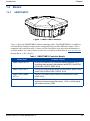
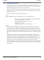
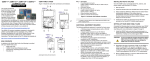
Figure 1: SMART-MR10 Receiver
Figure 1 shows the SMART-MR10 without connecting cables. The SMART-MR10 is available in
several different firmware models whose configurations may include additional features. Table 1
summarizes the available models. Contact your NovAtel dealer to get up-to-date information on
available models. For a list of dealers in your area, visit the NovAtel website at www.novatel.com
through Where to Buy | Dealers.
Table 1: SMART-MR10 Controller Models
Model Name
Firmware Feature
SMART-MR10-RT2-G
GPS plus GLONASS 1 cm real-time kinematic positions, RT-2
corrections and raw data, code positions and DGPS, OmniSTAR
HP/XP/VBS, CDGPS, SBAS, 20 Hz
SMART-MR10-HP-G
GPS plus GLONASS dual-frequency code positions, SBAS, DGPS,
OmniSTAR G2/HP/XP/VBS, CDGPS, 20 Hz
SMART-MR10-SBASPVT1-G
GPS plus GLONASS single-frequency code positions, SBAS,
DGPS, 20 Hz
SMART-MR10-G-Z
GPS plus GLONASS heading vector, including heading and
separation between master and remote; 10 Hz; must be paired
with another receiver, DGPS
SMART-MR10/15 User Manual Rev 4
25
Chapter 1
1.4.2
Introduction
SMART-MR15
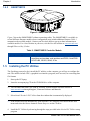
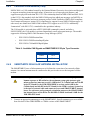
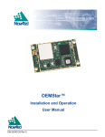
Figure 2: SMART-MR15 Receiver
Figure 2 shows the SMART-MR15 without connecting cables. The SMART-MR15 is available in
several different firmware models whose configurations may include additional features. Table 1
summarizes the available models. Contact your NovAtel dealer to get up-to-date information on
available models. For a list of dealers in your area, visit the NovAtel website at www.novatel.com
through Where to Buy | Dealer.
Table 2: SMART-MR15 Controller Models
Model Name
SMART-MR15-RT2-G
1.5
Firmware Feature
GPS plus GLONASS 1 cm real-time kinematic positions, RT-2
corrections and raw data, code positions and DGPS, OmniSTAR
HP/XP/VBS, CDGPS, SBAS, 20 Hz
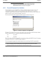
Installing the PC Utilities
The first thing you need to do is install the PC utilities on the computer you will use to configure the
unit. The utilities include CDU, a graphical user interface program, and Convert4, for converting data
file formats.
1.
Start up the PC/laptop.
2.
Insert the accompanying CD in the CD-ROM drive of the computer.
You can obtain the latest CDU (and PC utilities) version from the NovAtel website at
www.novatel.com through Support | Firmware/Software and Manuals.
3.
Select Install NovAtel’s PC Utilities from the window that is automatically displayed.
If the window does not automatically open when the CD is inserted, select Run from the Start
menu and select the Browse button to locate Setup.exe on the CD drive.
4.
26
Install the PC Utilities by advancing through the steps provided in the NovAtel PC Utilities setup
program.
SMART-MR10/15 User Manual Rev 4
Chapter 2
Installation
This chapter contains instructions for mounting and cabling your SMART-MR10/15.
2.1
Additional Equipment Required
The following additional equipment is required:
2.1.1
•
Mounting kit (see Section 2.1.1, Mounting Kits for details of mounting kits
available for the SMART-MR10/15)
•
SMART-MR10/15 cable (see Appendix D Replacement Parts starting on page 132
for part numbers). Refer to Figure 8, SMART-MR10/15 Cabling on page 33 for
COM and power connections.
•
A fused power supply (user-supplied)
Mounting Kits
Caution!:
When you are using your own mounting plate, adhere to the following guidelines
for maximum and minimum mounting-screw length:
Thickness of
Mounting Plate (T)
Total Length
of Screw
To ensure proper installation of your mounting plate to the SMART-MR10 and
SMART-MR15 units, the total length of the mounting screws must be:
- [T” + 0.45”] maximum and [T” + 0.25”] minimum for 1/4-20 screws or
- [Tmm + 11.5mm] maximum and [Tmm + 7mm] minimum for M6x1 screws.
Several NovAtel mounting kits are available, all of which come with four 1/4-20 screws for mounting
the SMART-MR10/15 to the mounting plate:
•
•
Mounting Kit, Quick Release Plate (part number 01018625), shown in Figure 3 on page 28.
Mounting Kit, Quick Release Assembly (part number 01018578), shown in Figure 4 on page 29.
The Mounting Kit, Quick Release Assembly (part number 01018578) includes a Mounting
Kit, Quick Release Plate (part number 01018625).
•
•
Mounting Kit, AG GPS 262 (part number 01018623), shown in Figure 5 on page 30.
Mounting Kit, 5/8 Inch Adapter (part number 01018624), shown in Figure 6 on page 31.
SMART-MR10/15 User Manual Rev 4
27
Chapter 2
Installation
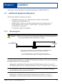
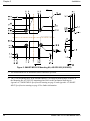
Figure 3: SMART-MR10/15 Mounting Kit, Quick Release Plate (01018625)
All measurements are in millimetres unless otherwise specified.
The 01018625 mounting kit can be used in several configurations:
- Stand-alone plate that is hard-mounted onto the implement
- Hard-mounted or quick-release mounted onto an intermediate plate
- As part of Mounting Kit, Quick Release Assembly, NovAtel part number 01018578
The mounting holes in the SMART-MR10/15 will align with the dimple locations in the
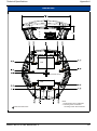
mounting plate. The 1/4-20 holes form a rectangular pattern. The M6x1 holes form a
trapezoidal pattern. Refer to the mechanical drawings in Appendix A.2 SMART-MR10
Specifications starting on page 81 and Appendix A.3 SMART-MR15 Specifications starting on
page 85 for further information.
28
SMART-MR10/15 User Manual Rev 4
Installation
Chapter 2
10.20
2X
51.08
12.80
R5.10
TYP.
269.7
32.00
16.00
13.70
179.70
248.7
208.70
100.00
50.00
40.00
12.50
TYP.
THE DIMENSIONS SHOWN ARE FOR THE
INTERMEDIATE MOUNTING PLATE, NOT
FOR THE ENTIRE QUICK RELEASE KIT.
280.00
27.46
31.00
334.9
NOTE: THE 01018578 MOUNTING
KIT, QUICK RELEASE ASSEMBLY
INCLUDES FOUR 1/4-20
MOUNTING SCREWS
UNIVERSAL MOUNTING PLATE 70023085
INTERMEDIATE
MOUNTING PLATE 70023089
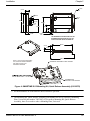
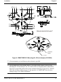
Figure 4: SMART-MR10/15 Mounting Kit, Quick Release Assembly (01018578)
All measurements are in millimetres unless otherwise specified.
The Mounting Kit, Quick Release Assembly (part number 01018578) includes a Mounting
Plate, Universal (part number 70023085). If you order a Mounting Kit, Quick Release
Assembly, there is no need to order a Mounting Plate, Universal.
SMART-MR10/15 User Manual Rev 4
29
Chapter 2
Installation
Figure 5: SMART-MR10/15 Mounting Kit, AG GPS 262 (01018623)
All measurements are in millimetres unless otherwise specified.
The 1/4-20 mounting holes in the SMART-MR10/15 will align with the dimple locations in
the Mounting Kit, AG GPS 262 mounting plate. Refer to the mechanical drawings in
Appendix A.2 SMART-MR10 Specifications starting on page 81 and Appendix A.3 SMARTMR15 Specifications starting on page 85 for further information.
30
SMART-MR10/15 User Manual Rev 4
Installation
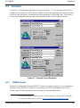
Chapter 2
INSERT
NOTE: THE 01018624 MOUNTING KIT, 5/8 INCH
ADAPTER INCLUDES FOUR 1/4-20 SCREWS
THREADED
INSERT
PLATE
Figure 6: SMART-MR10/15 Mounting Kit, 5/8 Inch Adapter (01018624)
All measurements are in millimetres unless otherwise specified.
The mounting holes in the SMART-MR10/15 will align with the dimple locations in the
Mounting Kit, 5/8 Inch Adapter. The 1/4-20 holes form a rectangular pattern, and the M6x1
holes form a trapezoidal pattern. Refer to the mechanical drawings in Appendix A.2 SMARTMR10 Specifications starting on page 81 and Appendix A.3 SMART-MR15 Specifications
starting on page 85 for further information.
SMART-MR10/15 User Manual Rev 4
31
Chapter 2
2.2
Installation
Mounting the SMART-MR10/15
When installing the SMART-MR10 or SMART-MR15:
2.3
•
Choose a location that has a clear view of the sky so that each satellite above the
horizon can be tracked without obstruction.
•
Mount the SMART-MR10 or SMART-MR15 on a secure, stable structure capable
of safe operation in the specific environment. A typical installation is on the vehicle
roof.
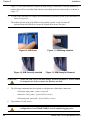
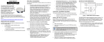
Cabling the SMART-MR10/15
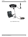
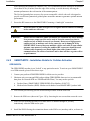
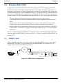
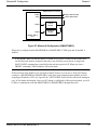
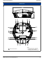
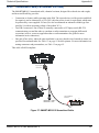
1.
Connect the cable to the SMART-MR10 or SMART-MR15 connector, shown in Figure 7 below.
Route the cable to the other system components and secure it. If you are using the NovAtel
streamlined cable, the system is as illustrated in Figure 8 on page 33. The pinouts for the
SMART-MR10/15 connector are described in Table 3 on page 34 and Table 5 on page 35.
Figure 7: SMART-MR10/15 Connector
32
SMART-MR10/15 User Manual Rev 4
Installation
Chapter 2
TNC connector
Cellular
Antenna
Tyco 23-pin
connector
COM1
User Supplied
5A Fuse
SMART-MR10: COM2
SMART-MR15: AUX
+
-
ER
Figure 8: SMART-MR10/15 Cabling
SMART-MR10/15 User Manual Rev 4
33
Chapter 2
Installation
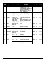
Table 3: SMART-MR10 Connector Pin-Out
Pin
Use
Pin
Use
1
PWR+
13
RESERVED
2
PWR-
14
CHASSIS GROUND
3
CAN1-
15
SIGGND1
4
CAN1+
16
MKI
5
TXD2
17
PPS
6
RXD2
18
ER
7
TXD1/TXD1+a
19
MODEa
8
RTS1/AUXTX/TXD1-a
20
RESERVED
9
SIGGND2
21
RESERVED
10
RESERVED
22
CTS1/AUXRX/RXD1-a
11
RESERVED
23
RXD1/RXD1+a
12
RESERVED
a. The SMART-MR10/15 is RS-232/RS-422-selectable through pin 19
MODE, as shown in Table 4.
Table 4: SMART-MR10 Use of MODE Pin
MODE Pin
34
Result
Pin-out
Open
Pins 8 and 22 provide RS-232 access
to the AUX port TX and RX lines.
COM1 flow control and COM1 RS422 TX- and RX- signals are not
available in this configuration.
Pin 7: TXD1
Pin 8: AUXTX
Pin 22: AUXRX
Pin 23: RXD1
(2 COM ports, no flow control)
Tied Low (connected
to ground)
Pins 8 and 22 provide TXD1- and
RXD1- for COM1 RS-422, and the
AUX port (AUXRX, AUXTX) is not
available.
Pin 7: TXD1+
Pin 8: TXD1Pin 22: RXD1Pin 23: RXD1+
(RS-422 only)
Tied High (connected
to positive side of
battery through a fuse)
Pins 8 and 22 provide RTS1 and
CTS1 for COM1 flow control, and the
AUX port (AUXTX, AUXRX) is not
available.
Pin 7: TXD1
Pin 8: RTS1
Pin 22: CTS1
Pin 23: RXD1
(1 COM port with flow control)
SMART-MR10/15 User Manual Rev 4
Installation
Chapter 2
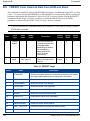
Table 5: SMART-MR15 Connector Pin-Out
Pin
Use
Pin
Use
1
PWR+
13
RESERVED
2
PWR-
14
CHASSIS GROUND
3
CAN1-
15
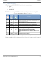
SIGGND1
4
CAN1+
16
MKI
5
AUXTX
17
PPS
6
AUXRX
18
ER
7
TXD1/TXD1+a
19
MODEa
8
RTS1/TXD1-a
20
RESERVED
9
SIGGND2
21
RESERVED
10
RESERVED
22
CTS1/RXD1-a
11
RESERVED
23
RXD1/RXD1+a
12
RESERVED
a. The SMART-MR15 is RS-232/RS-422-selectable through pin 19
MODE, as shown in Table 6.
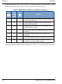
Table 6: SMART-MR15 Use of MODE Pin
MODE Pin
Result
Open or tied High
(connected to positive
side of battery through
a fuse)
Pins 8 and 22 provide RTS1 and
CTS1 for COM1 flow control, and the
AUX port (AUXTX, AUXRX) is not
available.
Pin 7: TXD1
Pin 8: RTS1
Pin 22: CTS1
Pin 23: RXD1
(1 COM port with flow control)
Tied Low (connected
to ground)
Pins 8 and 22 provide TXD1- and
RXD1- for COM1 RS-422, and the
AUX port (AUXRX, AUXTX) is not
available.
Pin 7: TXD1+
Pin 8: TXD1Pin 22: RXD1Pin 23: RXD1+
(RS-422 only)
WARNING!:
2.
Pin-out
If the MODE pin is tied high, it must be tied high through a fuse. In this case, MODE
can be tied to the same fuse as the red power lead, as illustrated in Figure 8, SMARTMR10/15 Cabling on page 33. It is never acceptable to connect wiring directly to the
positive side of the power source.
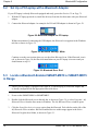
Turn on the power supply to the SMART-MR10/15. The power LED
SMART-MR10/15 User Manual Rev 4
on the back of the
35
Chapter 2
Installation
receiver lights red when the SMART-MR10/15 is properly powered.
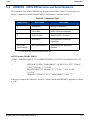
Minimum conductor size for all wiring is 0.5 mm / 20 AWG. While the AMPSEAL connector
can accommodate X mm / 20 AWG wire electrically, in order to ensure IP67 performance, the
wire insulation diameter needs to be no less than 2.2 mm / 0.0826 inches.
2.3.1
Connecting the Power Supply
The SMART-MR10/15 requires +9 to +36 VDC for the input power to the receiver. See Appendix A.2
starting on page 81 for SMART-MR10 power supply specifications, and Appendix A.3 starting on
page 85 for SMART-MR15 power supply specifications.
Fuse/holder recommendations can be found in Table 14, Recommended Fuses on page 93
The SMART-MR10/15 cable provides power in (with a BATT+ label) and power ground (with a
BATT- label) bare wires for connections from the SMART-MR10/15 to a vehicular power system
protected by a user-supplied fuse. NovAtel recommends an automotive blade-type fuse, rated for 5A
with an operating voltage of more than 36V. For cable details, refer to Appendix A.4.3, Custom
Connector and Cable Requirements starting on page 93.
WARNING!:
The SMART-MR10/15 power source must be protected by a 5A fuse or damage to
wiring may result (not covered by warranty). If the voltage supplied is above or
below the specified range, the receiver will suspend operation. If the voltage supplied
is above 48V, the receiver may be permanently damaged, voiding your warranty.
Once you apply power, the SMART-MR10/15 status lights will light as described in Status Indicators
starting on page 37.
36
SMART-MR10/15 User Manual Rev 4
Installation
2.3.2
Chapter 2
Status Indicators
LED indicators on the SMART-MR10/15 provide receiver status information:
•
Power
•
Position Status
•
Position Type
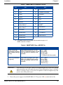
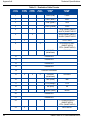
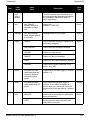
Table 7 shows the meaning of the LED states in the expected sequence after power is applied.
Table 7: SMART-MR10 LED Status Indicators
Red
Yellow
Green
Condition
Off
Off
Off
Power is not available. (Red indicator may also not be lit if a
boot failure has occurred.)
On
Off
Off
Power available but no satellites are being tracked
On
Flashing
Off
Tracking at least one satellite but not a valid position
On
On
Off
Position valid in basic autonomous mode
On
On
Flashing
SBAS tracking, but not enough data for enhanced solution.
On
On
On
Position valid in an enhanced accuracy modea
(WAAS/EGNOS/MSAS/DGPS, OmniSTAR VBS/XP/HP, or
RTK)
On
Flashing
Flashing
Fixed position with bad integritya
a. When acting as a reference receiver, all lights on solid indicates a good fixed position.
Flashing means that the LED is turning on and off at a 1 Hz rate - 0.5 seconds on and 0.5 seconds off.
SMART-MR10/15 User Manual Rev 4
37
Chapter 2
Installation
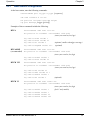
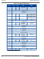
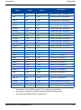
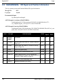
If the SMART-MR15 NTRIP client is not active, its LEDs will operate as outlined in Table 7. If the
SMART-MR15 NTRIP client is active, its LEDs will operate as outlined in Table 8.
Table 8: SMART-MR15 LED Behavior (NTRIP Client Active)
Red
Yellow
Green
Condition
Off
Off
Off
Power is not available. (Red indicator may also not be lit if a
boot failure has occurred.)
On
Off
Off
Power available but no satellites are being tracked. No
cellular network connection.
On
Flashing
Off
Tracking at least one satellite but not a valid position. No
cellular network connection.
On
On
Off
Position valid in basic autonomous mode. No cellular network
connection.
On
On
Flashing
On
On
On
On
Flashing
Flashing
Connected to cellular network but not receiving RTK
corrections.
Connected to cellular network and receiving RTK corrections.
Fixed position with bad integrity Connected to cellular
network but not receiving RTK corrections.
Flashing means that the LED is turning on and off at a 1 Hz rate - 0.5 seconds on and 0.5 seconds off.
38
SMART-MR10/15 User Manual Rev 4
Installation
2.3.3
Chapter 2
Debugging Guidelines:
•
If the power is on but the yellow LED does not flash within one minute, then no satellites are
being tracked. There may be excessive blockage or the unit may be defective. Make sure the unit
has an unobstructed view of the sky. Try power cycling the unit.
•
If the yellow LED does not flash within one minute and power cycling the unit does not fix the
problem, once you have a computer or terminal connected, request a VERSION log to ensure that
the auth code is correct.
Example of a receiver loaded with an incorrect auth code:
<OK
[COM1]<VERSION COM1 0 94.5 UNKNOWN 0 156.357 004C0001 3681 5010
<3
<
GPSCARD "Invalid Authcode" "DHC09401037" "MCAGTP-1.00-22B"
"3.710" "3.002" "2009/NOV/30" "11:08:19"
<
DB_USERAPPAUTO "SmartAg" "0" "" "1.100" ""
"2009/NOV/27" "13:22:29"
<
USERINFO "LMX9830" "0212" "002166000001" "" "" "" ""
[COM1]
• If the yellow LED is flashing but does not progress to solid yellow within one minute, then
insufficient satellites are being tracked or the signal quality is poor and ephemeris data can’t be
received. Normally, four satellites are sufficient for a valid position as long as they are widely
distributed in the sky. If it is stuck on blinking yellow, there may be excessive blockage or the unit
may be defective. Make sure the unit has an unobstructed view of the sky. Try power cycling the
unit.
•
If the yellow LED is on, but the green does not turn on within five minutes then no SBAS or
DGPS positions are available. If you are using SBAS, make sure SBAS is available in your area
and that the unit is configured to enable SBAS positions (SBASCONTROL ENABLE). For
DGPS, make sure the unit is configured with the correct serial port parameters and to accept the
DGPS protocol your area is using, and that your data modem is connected and working.
•
For the SMART-MR10 or the SMART-MR15 with NTRIP disabled, the green LED blinks when
SBAS is detected then it comes on solid when SBAS is enabled. The LED will stay dark if SBAS
is not detected.
SMART-MR10/15 User Manual Rev 4
39
Chapter 2
2.3.4
Installation
Connecting Data Communications Equipment
To communicate with the receiver so that you can send commands to and obtain logs from the
SMART-MR10/15, you will need to connect it to a terminal or computer. For further information
about the data communications connector and pin-out details for the evaluation and streamlined
cables, see Table 11, Evaluation Cable Pinouts on page 90 and Table 12, Streamlined Cable Pinouts
on page 92 respectively. Once you are connected, you will be able to carry out the operations outlined
in Chapter 3, Operation starting on page46, Appendix B Commands starting on page 94, and
Appendix C Logs starting on page 118.
2.4
Additional Installation Information
This section provides additional installation and configuration information that relate to specific
applications of the SMART-MR10/15.
2.4.1
MKI and PPS Strobes
Input (MKI) and output (PPS) strobes provide status and synchronization signals. PPS is a 3.3V
CMOS output; MKI is a 5V-tolerant input. PPS and MKI are referenced to SGND. Pin-out
information can be found on Table 11 on page 90.
MKI can be used in conjunction with the MARKTIME and MARKPOS logs. For information about
these logs, refer to OEMV Family Firmware Reference Manual, available on the NovAtel website at
www.novatel.com through Support | Firmware/Software and Manuals.
2.4.2
Emulated Radar (ER)
The SMART-MR10/15 output an emulated radar signal via the bare wires labeled SGND and
ER OUT on the SMART-MR10/15 cable. See Table 11 on page 90 or Table 12 on page 92 for the pinout details of your cable.
The ER outputs:
•
•
•
•
Logic high: Minimum of supply voltage minus 0.5V
Logic low: Maximum of 0.5V
Minimum load: 3k ohms
Rise and fall time: Less than 1 ms.
The ER output is referenced to signal GND and provides logic low output until its speed is greater
than 1 km/hr. ER can be configured to operate at one of three distinct frequencies (26.11, 28.12 or
36.11 Hz/km/hr, with 36.11 Hz/km/hr being the default value) and with an effective velocity range
from 1 km/hr to 55 km/hr for near-horizontal applications. See Appendix B.12 RADARCFG Configure
the ER output starting on page 113 for more information.
40
SMART-MR10/15 User Manual Rev 4
Installation
2.4.3
Chapter 2
Controller Area Network (CAN)
NMEA 2000 is a CAN standard created by the National Marine Electronics Association and designed
to support networking in marine applications. It functions over a longer physical distance, and
supports more physical nodes than ISO 11783. The relationship between NMEA 2000 and SAE J1939
is that J1939 is the standard, while the NMEA 2000 group has added new messages (called PGNs or
Parameter Group Numbers) and a new transport protocol called FastPacket. NMEA 2000 compliant,
for all intents and purposes, means J1939 compliant plus support for new NMEA 2000 messages. In
other word, one cannot have NMEA 2000 without J1939 support as well. J1939 is additionally
“harmonized” with ISO 11783, a standard for the agriculture industry.
The CAN module is activated when a SETCANNAME command is entered, and after a
SAVECONFIG, the CAN module is activated immediately on all subsequent start-ups. The module
supports the following NMEA 2000 Parameter Group Messages (PGN):
•
PGN 129029 GNSSPositionData
•
PGN 129025 GNSSPositionRapidUpdate
•
PGN 129026 COGandSOGRapidUpdate
Table 9: Available CAN Signals on SMART-MR10/15 23-pin Tyco Connector
2.4.4
CAN
Pins
CAN1-
Pin 3
CAN1+
Pin 4
SMART-MR15 CELLULAR ANTENNA INSTALLATION
The SMART-MR15 has a cellular antenna port to facilitate the connection of an external cellular
antenna. An external antenna must be connected to this port in order to use the integrated cellular
modem.
WARNING!:
1.
To comply with FCC regulations limiting both maximum RF output power and
human exposure to RF radiation, the maximum system gain (antenna gain
minus system loss) must not exceed 1.4 dBi in the U.S. Cellular band and 3.0 dBi
in the PCS band for the GSM/GPRS/HSDPA variant, and 6.0 dBi in the
Cellular band and 6.0 dBi in the PCS band for the CDMA variant. System loss
is the total of external cable and connector losses and SMART-MR15 internal
losses. For reference and system gain calculation purposes, the SMART-MR15
has internal losses of 0.6 dB for the 800 MHz Cellular band and 1.8 dB for the
1900 MHz PCS band.
Connect an appropriate antenna type to the SMART-MR15: Specific antenna types are available
from NovAtel for the GPRS/HSDPA or CDMA versions of the SMART-MR15.
SMART-MR10/15 User Manual Rev 4
41
Chapter 2
Installation
WARNING!:
Do not connect a CDMA antenna to a GPRS/HSDPA version of the SMARTMR15 as this creates a safety hazard.
WARNING!:
Do not shorten the cable lengths provided with any particular antenna type as
this creates a safety hazard.
CAUTION!:
Do not connect a GSM antenna type to a CDMA version of the SMART-MR10
as cellular performance is degraded.
2.
Ensure the cellular antenna is installed at least 30 cm away from the SMART-MR15, as shown in
Figure 9. GNSS positioning accuracy may be degraded if this is not observed, particularly for
operation in the EU “1800 MHz” band.
CELLULAR ANTENNA
NOTE: DIMENSIONS SHOWN
ARE IN MILLIMETRES (mm)
Figure 9: Cellular Antenna Placement
3.
Ensure the cellular antenna is installed at least 20 cm away from the Bluetooth antenna area of the
SMART-MR15, as shown in Figure 9.
The previous requirement should always satisfy this requirement.
4.
42
Antennas must be installed on a “ground plane”. A vehicle with a metal roof is inherently a
ground plane. For vehicles with a non-metallic roof a metal ground plane (available from NovAtel) must be used.
SMART-MR10/15 User Manual Rev 4
Installation
Chapter 2
When installing the antenna on a metallic roof, it is recommended that the antenna be installed no
closer than 10 cm, (4 inches) from the edge of the rooftop, to avoid adversely affecting the
antenna performance due to distortion of the antenna pattern.
The NovAtel ground plane accessory for use on non-metallic vehicle cab roofs is designed to
provide a sufficient symmetrical ground plane around the antenna to guarantee optimal antenna
performance.
5.
Secure the RF connector to the SMART-MR15 ensuring a “hand tight” connection.
WARNING!:
Do not use pliers or other tool types to over-tighten the RF connector as damage
to the connector will occur.
WARNING!:
Ensure the RF connectors (male and female) are clean and dry before mating.
Low pressure compressed air can be used to clean the connectors (that is,
compressed air available in aerosol can format). Do not use a high pressure
compressed air as moisture seals in the connector can be damaged. If the
SMART-MR15 is moved between multiple vehicles each with its own cellular
antenna, some means of sealing the unmated RF connectors should be used.
Cellular radio frequencies are much higher than older forms of radio
communications; the effects of moisture and/or dust will have a greater effect
on performance.
2.4.5
SMART-MR15 - Installation Details for Cellular Activation
GPRS/HSDPA
The GPRS/HSDPA modem is not “locked” to any particular carrier. To activate your SMART-MR15
on a GSM network, please follow these steps:
1.
Contact your preferred GSM/GPRS/HSDPA cellular service provider.
2.
Obtain an active account and SIM card providing GPRS/HSDPA data services (recommended
data plans for Network RTK are 5GB/Month Rate Plans). You may need to provide:
a.
b.
Product Name: SMART-MR15 GPRS/HSDPA [Part Number: 01018712]
Modem Serial Number (IMEI): Modem serial number from SMART-MR15 product label
Your cellular provider may provide an activation procedure with the SIM card.
3.
Remove the SIM cover (shown in Figure 10) by loosening the two screws that secure the cover.
When you are replacing the SIM cover, make sure it is installed straight or you may
inadvertently cause the SIM card to eject.
4.
Install the SIM following the orientation shown on the SIM cover (notch up and in, as shown in
SMART-MR10/15 User Manual Rev 4
43
Chapter 2
Installation
Figure 11). The SIM connector is a push -in/push-out type. If the SIM is correctly installed, its
outside edge will be essentially flush with the surrounding enclosure metal surface, as shown in
Figure 12.
To remove the SIM push it in slightly and it should then be partially ejected by the SIM holder, as
shown in Figure 13.
The modem will not work if the SIM is in the partially ejected “ready for removal”
position.Ensure the SIM door is properly aligned, then secure it in place.
Figure 10: SIM Cover
Figure 11: SIM Being Installed
Figure 12: SIM Correctly Installed
Figure 13: SIM Ready for Removal
WARNING!:
5.
Secure the SIM cover to the base using a flat-head screwdriver. Screws should
be torqued to 4-6 in-lb, to ensure the unit does not leak.
The following commands may be required to configure the cellular data connection:
cellset apn <apn_name> {always required}
cellset user <user_name> {if provided by carrier}
cellset password <password> {if provided by carrier}
6.
Your product is ready for use.
CAUTION!:
44
Cellular data consumption and service charges are dependent on the
configuration of your SMART-MR15 receiver and data logging rates.
SMART-MR10/15 User Manual Rev 4
Installation
Chapter 2
CDMA
To activate your SMART-MR15 on the Verizon network:
1.
Obtain a Verizon Wireless Account. You will need to provide:
a.
b.
2.
Product Name: SMART-MR15 CDMA (Verizon) [Part Number: 01018606]
Modem Serial Number (MEID) from the SMART-MR15 product label
Activate the modem with Verizon:
a.
b.
Apply power and establish a serial connection with your product.
Send the following logs and commands:
NovAtel Command
Guidance
LOG CELLSTATUS
Check the number of bars to confirm signal strength OK.
CELLACTIVATE verizon
This will provision the module on the Verizon network
SMART-MR10/15 User Manual Rev 4
45
Chapter 3
Operation
Before operating the SMART-MR10 or SMART-MR15 for the first time, ensure that you have
followed the installation instructions in Chapter 2 Installation starting on page 27. The following
instructions are based on a COM port configuration such as that shown in Figure 15 on page 50. It is
assumed that a personal computer (PC), or laptop, is used during initial operation and testing for
greater ease and versatility.
3.1
Communications with the Receiver
Communication with the receiver typically consists of issuing commands through the communication
ports from an external serial communications device. This could be either a terminal or PC/laptop that
is directly connected to the receiver serial port using a DB-9 connector on the SMART-MR10 or
SMART-MR15 multi-cable. If you are using a radio, it connects to another DB-9 connector on the
same multi-cable by means of the radio serial cable supplied with the radio. It is recommended that
you become thoroughly familiar with the commands and logs detailed in the OEMV Family Firmware
Reference Manual to ensure maximum utilization of the receiver’s capabilities.
3.1.1
Serial Port Default Settings
The receiver communicates with your PC/laptop or terminal via an RS-232 serial port. For
communication to occur, both the receiver and the operator interface have to be configured properly.
The receiver’s COM1, COM2 and AUX default port settings are configured as follows:
•
9600 bps, no parity, 8 data bits, 1 stop bit, no handshaking, echo off
Changing the default settings requires use of the COM command. See Appendix B.5, COM Configure
COM Port starting on page 99 for details.
SMART-MR15 COM2 is restricted to internal use by the cellular radio. Do not modify the
settings for this port.
COM1 can be configured as RS-422. It can also be configured with flow control. AUX is not
available if COM1 flow control is enabled or if COM1 is configured as RS-422. The default
configuration, with the MODE pin unconnected, is that COM1 is RS-232 with no flow
control. The configuration using the Mode pin is summarized in Table 5, SMART-MR15
Connector Pin-Out on page 35.
The data transfer rate you choose determines how fast information is transmitted. Take for example a
log whose message byte count is 96. The default port settings allows 10 bits/byte (8 data bits + 1 stop
bit + 1 framing bit). It therefore takes 960 bits per message. To get 10 messages per second then
requires 9600 bps. Also remember that even if you set the bps to 9600 the actual data transfer rate is
lower and depends on the number of satellites being tracked, data filters in use, and idle time. It is
suggested that you leave yourself a margin when choosing a data rate (115200 is recommended for
46
SMART-MR10/15 User Manual Rev 4
Operation
Chapter 3
most applications).
CAUTION!:
3.1.2
Although the receiver can operate at data transfer rates as low as 300 bps, this
is not desirable. For example, if several data logs are active (that is, a significant
amount of information needs to be transmitted every second) but the bit rate is
set too low, data will overflow the serial port buffers, cause an error condition
in the receiver status and result in lost data.
Communicating Using a Remote Terminal
One method of communicating with the receiver is through a remote terminal. The receiver has been
pre-wired to allow proper RS-232 interface with your data terminal. To communicate with the
terminal, the receiver only requires the RX, TX, and GND lines to be used. Request to Send (RTS)/
Clear to Send (CTS) hardware handshaking is not available. Ensure the terminal’s communications
set-up matches the receiver’s RS-232 protocol.
3.1.3
Communicating Using a Personal Computer
A PC/laptop can be set up to emulate a remote terminal as well as provide the added flexibility of
creating multiple-command batch files and data logging storage files. Any standard communications
software package that emulates a terminal can be used to establish bidirectional communications with
the receiver, for example, HyperTerminal or our own graphic user interface (GUI) program, CDU. All
data is sent as raw 8-bit binary or ASCII characters.
3.2
Getting Started
Included with your receiver are NovAtel’s CDU and Convert4 programs. CDU is a Windows-based
GUI which allows you to access the receiver's many features without the need for communications
protocol or to write special software. The Convert4 utility is a Windows-based utility that allows you
to convert receiver logs between ASCII and binary formats, and strips unwanted records for data file
compilation. If you have not already installed these utilities, see Section 1.5, Installing the PC Utilities
on page 26.
3.2.1
Starting the Receiver
When first powered, the SMART-MR10/15 undergo a complete self-test. If an error condition is
detected during a self-test, the self-test status word changes. This self-test status word can be viewed
in the header of any data output log. Refer to the chapter on Messages in the OEMV Family Firmware
Reference Manual for header information. If a persistent error develops, please contact your local
NovAtel dealer first. If the problem is still unresolved, please contact NovAtel directly through any of
the methods listed in the Customer Support section at the beginning of this manual on page 20.
SMART-MR10/15 User Manual Rev 4
47
Chapter 3
3.2.2
Operation
Communicating with the Receiver Using CDU
Launch the CDU program and select Device | Open from its main menu. The Open Configuration
window appears. Figure 14, below, shows an Open Configuration window with three possible
configurations already set up. Your configurations may be different or you may have none at all, in
which case, the Open Configuration window is empty.
Figure 14: Open Configuration Window
Refer to CDU’s help file by selecting the Help | Contents menu. Ensure you can see the Console and
ASCII Messages windows by selecting them from the View menu.
When the receiver is first turned on, no data is transmitted from the COM ports except for the port
prompt. The console window displays a port name:
[COM1] if connected to COM1 port,
or
[COM2] if connected to COM2 port,
Any of the above prompts indicate that the receiver is ready and waiting for command input.
1.
2.
48
You may also have to wait for output from receiver self tests. For example, on start-up,
the OEMV family receiver is set to log the RXSTATUSEVENTA log ONNEW on all
ports. Refer to the OEMV Family Firmware Reference Manual for more details.
If you find that CDU is unable to locate your OEMV family receiver, it may be that you
have previously used the SAVECONFIG command. In this case, try using a different
COM port to communicate with the receiver. Once communication has been established,
issue the command FRESET STANDARD. You should now be able to use your original
communication port again.
SMART-MR10/15 User Manual Rev 4
Operation
Chapter 3
Commands are typed at the interfacing computing device’s keypad or keyboard, and executed after
issuing a carriage return command which is usually the same as pressing the <Enter> key.
An example of a response to an input command is the FIX POSITION command is shown below:
[COM2] fix position 51.11635 -114.0383 1048.2 [carriage return]
<OK
where [COM2] is the port prompt, followed by the command you enter from your keypad or keyboard
and [carriage return] indicates that you should press the <Enter> key.
The above example illustrates the command input to the base receiver’s COM2 port, which sets the
position of the base station receiver for differential operation. Confirmation that the command was
actually accepted is the appearance of <OK.
If a command is entered incorrectly, the receiver responds with:
<INVALID MESSAGE ID
CAUTION!:
3.3
(or a more detailed message)
Ensure the Control Panel’s Power Settings on your PC/laptop are not set to go
into Hibernate or Standby modes. Data will be lost if one of these modes occurs
during a logging session.
Transmitting and Receiving Corrections
RTK or DGPS corrections can be transmitted from a base station to a rover station to improve position
accuracy. The base station is the GNSS receiver, which is acting as the stationary reference. It has a
known position and transmits correction messages to the rover station. The rover station is a GNSS
receiver which can be sent correction messages from a base station to calculate differential GNSS
positions. The SMART-MR10/15 can be used as base receivers to transmit RTK or DGPS corrections,
or as rovers to receive the same corrections. An example of a differential setup is given in Figure 15
on page 50.
While the setup described in the following sections may work on a SMART-MR15, the
SMART-MR15 is designed to receive corrections over a cellular modem on COM2 via
NTRIP caster, in which case, the NTRIPCASTER and NTRIPCLIENT commands will take
care of all interface mode configuration and corrections. Users should not change the COM2
interface settings manually or the receiver will no longer be able to communicate with the
cellular modem.
SMART-MR10/15 User Manual Rev 4
49
Chapter 3
Operation
7
1
+
2
-
Rover
3
Base
1
2
+
3
COM1
4
-
COM1
COM2
5
6
COM2
5
Figure 15: Basic Differential Setup
Reference
Description
1
Receiver
2
User-supplied 5A fuse
3
User-supplied power supply, for example a battery
4
User-supplied device to COM1
5
User-supplied radio device to COM2 (SMART-MR10 only)
6
User-supplied PC/laptop, for setting up and monitoring, to COM1
7
Cellular Antenna (SMART-MR15 only)
System biases can introduce errors. Refer to the Support page on the NovAtel website at
www.novatel.com for more information. In most cases you need to provide a data link between the
base station and rover station (two NovAtel receivers) in order to receive corrections. The application
of SBAS corrections to a single receiver are an exception to the base/rover concept. Generally, a link
capable of data throughput at a rate of 9600 bits per second, and less than 4.0 s latency, is
recommended.
Once your base and rover are set up, you can configure them as outlined in the configuration examples
in 3.3.1, Base Station Configuration on page 51 and 3.3.2, Rover Station Configuration on page 52.
50
SMART-MR10/15 User Manual Rev 4
Operation
3.3.1
Chapter 3
Base Station Configuration
At the base station, enter the following commands:
interfacemode port rx_type tx_type [responses]
com com2 115200 N 8 1 N off
fix position latitude longitude height
log port message [trigger [period]]
Examples of these commands include the following:
RTCA
interfacemode com2 none rtca off
fix position 51.11358042 -114.04358013 1059.4105
(enter your own lat, lon, hgt)
log com2 rtcaobs ontime 1
log com2 rtcaref ontime 10
log com2 rtca1 ontime 5
(optional, enable code-dgps coverage)
(optional)
log com2 rtcaephem ontime 10 1
RTCAOBS2
interfacemode com2 none rtca off
(recommended) fix position 51.11358042 -114.04358013 1059.4105
(enter your own lat, lon, hgt)
log com2 rtcaobs2 ontime 1
log com2 rtcaref ontime 10
RTCM V2.3
interfacemode com2 none rtcm off
fix position 51.11358042 -114.04358013 1059.4105
(enter your own lat, lon, hgt)
log
log
log
log
RTCM V3
com2
com2
com2
com2
rtcm3 ontime 10
rtcm22 ontime 10 1
rtcm1819 ontime 1
rtcm1 ontime 5
(optional)
interfacemode com2 none rtcmv3 off
fix position 51.11358042 -114.04358013 1059.4105
(enter your own lat, lon, hgt)
log com2 rtcm1002 ontime 1
(for L1 only models)
log com2 rtcm1004 ontime 1
log com2 rtcm1006 ontime 10
log com2 rtcm1019 ontime 120
SMART-MR10/15 User Manual Rev 4
51
Chapter 3
Operation
RTCM V3 with GLONASS
interfacemode com2 none rtcmv3 off
(recommended) fix position 51.11358042 -114.04358013 1059.4105
(enter your own lat, lon, hgt)
log com2 rtcm1002 ontime 1
(for L1 only models)
log com2 rtcm1004 ontime 1
(for L1/L2 models)
log com2 rtcm1010 ontime 1
(for L1 only models)
log com2 rtcm1012 ontime 1
(for L1/L2 models)
log com2 rtcm1006 ontime 10
log com2 rtcm1033 ontime 10
log com2 rtcm1019 ontime 120
log com2 rtcm1020 ontime 120
CMRPLUS (CMR+)
interfacemode com2 none cmr off
fix position 51.11358042 -114.04358013 1059.4105
(enter your own lat, lon, hgt)
log com2 cmrobs ontime 1
log com2 cmrgloobs ontime 1
log com2 cmrplus ontime 1 (important to use ontime 1 with cmrplus)
CMR
interfacemode com2 none cmr off
fix position 51.11358042 -114.04358013 1059.4105
(enter your own lat, lon, hgt)
log
log
log
log
3.3.2
com2
com2
com2
com2
cmrobs ontime 1
cmrgloobs ontime 1
cmrref ontime 10
cmrdesc ontime 10 1
(optional)
Rover Station Configuration
At the rover station, enter:
interfacemode port rx_type tx_type (responses)
For example:
RTCA
interfacemode com2 rtca none off
RTCAOBS2
interfacemode com2 rtca none off
RTCM V2.3
interfacemode com2 rtcm none off
RTCM V3
interfacemode com2 rtcmv3 none off
RTCM V3 with GLONASS
interfacemode com2 rtcmv3 none off
52
CMR+
interfacemode com2 cmr none off
CMR
interfacemode com2 cmr none off
(same as CMR+)
SMART-MR10/15 User Manual Rev 4
Operation
3.3.3
Chapter 3
GPS + GLONASS Base and Rover Configuration
This section shows you how to set up your base and rover OEMV GPS + GLONASS-enabled
receivers for GPS + GLONASS RTK operation:
Base Station:
fix position lat lon hgt
(enter your own lat, lon, and hgt values)
com com2 115200 N 8 1 N off
interfacemode com2 none rtca off
log com2 rtcaref ontime 10
log com2 rtcaobs2 ontime 1
log com2 rtca1 ontime 5
(optional, enable code-DGPS coverage)
saveconfig
(optional, save configuration to non-volatile memory)
Rover Station:
com com2 115200 N 8 1 N off
interfacemode com2 rtca none off
log com1 bestposa ontime 1
(optional, view position information)
saveconfig
(optional, save configuration to non-volatile memory)
SMART-MR10/15 User Manual Rev 4
53
Chapter 3
3.3.4
Operation
Configuration Notes
For compatibility with other GNSS receivers, and to minimize message size, it is recommended that
you use the standard form of RTCA, RTCM, RTCMV3 or CMR corrections as shown in the base and
rover examples above. This requires using the INTERFACEMODE command to dedicate one
direction of a serial port to only that message type. When the INTERFACEMODE command is used
to change the mode from the default, NOVATEL, you can no longer use NovAtel format messages.
If you want to mix NovAtel format messages and RTCA, RTCAOBS2, RTCM, RTCMV3, CMR+ or
CMR messages on the same port, you can leave the INTERFACEMODE set to NOVATEL and log out
variants of the standard correction messages with a NovAtel header. ASCII or binary variants can be
requested by simply appending an “A” or “B” to the standard message name. For example on the base
station:
interfacemode com2 novatel novatel
fix position 51.11358042 -114.04358013 1059.4105
log com2 rtcm1b ontime 2
Using the receiver in this mode consumes more CPU bandwidth than using the native
differential messages shown in Section 3.3.1, Base Station Configuration on page 51.
At the rover station you can leave the INTERFACEMODE default settings (interfacemode com2
novatel novatel). The rover receiver recognizes the default and uses the corrections it receives with a
NovAtel header.
The PSRDIFFSOURCE and RTKSOURCE commands set the station ID values which identify the
base stations from which to accept pseudorange or RTK corrections respectively. They are useful
commands when the rover station is receiving corrections from multiple base stations.
All PSRDIFFSOURCE entries fall back to SBAS (even NONE) for backwards compatibility.
At the base station it is also possible to log out the contents of the standard corrections in a form that is
easier to read or process. These larger variants have the correction fields broken out into standard
types within the log, rather than compressed into bit fields. This can be useful if you wish to modify
the format of the corrections for a non-standard application, or if you wish to look at the corrections
for system debugging purposes. These variants have “DATA” as part of their names (for example,
RTCADATA1, RTCMDATA1, CMRDATAOBS, and more). Refer also to the OEMV Family
Firmware Reference Manual, which describes the various message formats in more detail.
Information on how to send multiple commands and log requests using DOS or Windows, can
be found on our website at www.novatel.com through Support | Help Desk & Solutions |
Search Known Solutions.
54
SMART-MR10/15 User Manual Rev 4
Operation
3.3.5
Chapter 3
SBAS (Satellite-Based Augmentation Systems)
A Satellite-Based Augmentation System (SBAS) is a type of geostationary satellite system that
improves the accuracy, integrity, and availability of the basic GNSS signals. Accuracy is enhanced
through the use of wide area corrections for GNSS orbits and ionospheric errors. Integrity is enhanced
by the SBAS network quickly detecting satellite signal errors and sending alerts to receivers to not use
the failed satellite. Availability is improved by providing an additional ranging signal to each SBAS
geostationary satellite.
OEMV family receivers, including the SMART-MR10/15, are capable of SBAS positioning. This
positioning mode is enabled using the SBASCONTROL command. The following command is used
to automatically track and use the SBAS service available in the area of operation, for example,
WAAS or EGNOS:
sbascontrol enable auto
For further information on SBASCONTROL, refer to the OEMV Family Installation and Operation
User Manual, available from the NovAtel website at www.novatel.com through Support | Firmware/
Software and Manuals.
WAAS (Wide-Area Augmentation System)
The US Federal Aviation Administration (FAA) has developed a Wide Area Augmentation System
(WAAS) to provide accurate positioning to the aviation industry. As well as providing the industry
with this high quality service, it is available to all other civilian users and markets in North America,
free of charge. Future developments to this system will encompass the L5 signal.
EGNOS (European Geostationary Navigation Overlay Service)
EGNOS has been developed to work with existing satellite navigation systems to improve the
accuracy of navigation signals. The EGNOS signal is transmitted by two geostationary satellites and
covers all of Europe. EGNOS transmits a signal containing information on the reliability and accuracy
of the positioning signals sent out by GPS.
At the time of this writing, the signal broadcast by the EGNOS satellites AOR-E (PRN120) and the
ESA ARTEMIS satellite (PRN 124) is used for EGNOS Operations. The EGNOS satellite IOR-W
(PRN 126) is currently used by Industry to perform various tests on the system.
More information on EGNOS can be found at http://www.esa.int/egnos.
SMART-MR10/15 User Manual Rev 4
55
Chapter 3
3.4
Operation
GL1DE®
SMART-MR10/15 contain NovAtel’s GL1DE, a positioning algorithm for single frequency GPS and
GPS/GLONASS applications. GL1DE produces a smooth position output tuned for applications
where optimal time relative (pass-to-pass) accuracy is more important than absolute accuracy, making
it well suited for agricultural applications.
Multipath signals tend to induce time-varying biases and increase the measurement noise on the L1
pseudorange measurements. Carrier phase measurements are much less susceptible to the effects of
multipath. The GL1DE algorithm combines the information from the L1 code and the L1 phase
measurements into a Position-Time-Velocity (PVT) solution.
GL1DE includes settings for a dynamic mode, a static mode, and an “auto” mode, where the filtering
parameters are automatically adjusted as vehicle velocity varies between stationary and dynamic
states.
Refer to the NovAtel white papers on the NovAtel website at www.novatel.com through Support |
Knowledge and Learning for more information on GL1DE. Refer also to application note “APN-038
Pseudorange/Delta-Phase (PDP) and GL1DE Filters”.
3.5
ALIGN®
3.5.1
ALIGN Heading Master and Remote Configurations
This section shows you how to set up a master station with an ALIGN-capable remote receiver for
applications that require heading output. Refer to APN-048, available from our website for more
details on setting up a heading configuration.
Master:
interfacemode com2 none rtca off
fix position lat lon hgt
(enter your own lat, lon, and hgt values)
movingbasestation enable
log com2 rtcaobs2 ontime 1
log com2 rtcaref ontime 10
If your master receiver will be on a moving platform (vehicle or marine vessel, for example),
then you must use the command MOVINGBASESTATION ENABLE.
Remote:
interfacemode com2 rtca none off
56
log headinga onchanged
(heading, baseline length, pitch and other data)
log gphdt onchanged
(NMEA heading formatted log)
SMART-MR10/15 User Manual Rev 4
Operation
3.6
Chapter 3
Emulated Radar (ER)
A typical radar sensor emits radio beams that bounce off the ground, and computes ground speed
based on the speed at which objects are passing in front of the sensor. The output of the sensor is a
digital pulse, the frequency of which is proportional to the vehicle’s ground speed. This is often used
in agricultural applications such as planting and spraying. The SMART-MR10/15 eliminate the need
for separate ground-sensing radar equipment by converting the GPS-derived velocity to proportional
frequency output. The following emulated radar signal parameters can be configured by the customer:
•
•
•
Frequency Step: Specifies how the frequency output relates to the vehicle speed.
Signal Update Rate: Specifies how often the frequency output is updated to match the vehicle
speed.
Response Mode: Specifies how quickly changes in velocity are reflected in the frequency output.
Setting a slower response mode reduces spikes (noise) in the velocity but increases latency.
Setting a higher response mode reduces latency, but may result in noisier frequency output. Refer
to Appendix B.12, RADARCFG Configure the ER output starting on page 113 for more detailed
information.
Once it is configured using the RADARCFG command (see page 113), Emulated Radar (ER) data is
output through the SMART-MR10/15 cables (see Table 11 on page 90) and the RADARSIGNAL log
(see page 125).
3.7
NTRIP Client
In this configuration, shown in Figure 16, a vehicle-mounted SMART-MR15 acts as a rover using
network RTK via NTRIP. To access NTRIP servers, the SMART-MR15 uses a built-in TCP/IPcapable cellular modem and NTRIP client software.
Wireless
Network
Wireless
Gateway
NTRIP Corrections
over
TCP/IP
NTRIP Requests
(typically GPGGA)
NTRIP Corrections
over TCP/IP
NTRIP
Caster
NTRIP
Server
(example,
CORS)
NTRIP
Source
Figure 16: NTRIP Client Configuration
SMART-MR10/15 User Manual Rev 4
57
Chapter 3
Operation
The following are examples of connecting to NTRIP clients:
Connecting to www.igs-ip.net (no GPGGA logs):
ntripcaster www.igs-ip.net 80
ntripclient mount prds0 userid password rtcmv3
Connecting to www.igs-ip.net
ntripcaster www.igs-ip.net 80
ntripclient mount prds0 userid password rtcmv3 10
(and send one GPGGA log to the NTRIP server every ten seconds)
3.8
Recommended Configuration
The following command is recommended to enable CAN:
setcanname 305
The following command is recommended to enable SBAS (WAAS/EGNOS/MSAS) corrections:
sbascontrol enable
sbascontrol enable EGNOS 0 zerototwo
The following commands are recommended to enable GL1DE:
pdpfilter enable
pdpmode relative auto
The cellular modem (SMART-MR15 only) is automatically enabled on start up. To set up the NTRIP
corrections, the following commands are recommended:
ntripcaster <address> <port>
ntripclient mount <mountpoint> <username> <password>
<correctiontype>
NovAtel has registered manufactured ID code 305 with J1939. When complete, your configuration
can be saved with the SAVECONFIG command. Refer to the OEMV Family Firmware Reference
Manual for further details on these commands.
58
SMART-MR10/15 User Manual Rev 4
Chapter 4
PC Utilities
Visit NovAtel’s website at www.novatel.com through Support | Firmware/Software and Manuals for
the most recent versions of the PC software and receiver firmware.
4.1
CDU/Convert4 Installation
The CD accompanying this manual contains the Windows applications CDU (Control and Display
Unit) and Convert4. They are installed via a standard Install Shield set-up application. Also included
on the CD is sample source code, to aid development of software for interfacing with the receiver, and
product documentation.
These applications utilize a database in their operations so the necessary components of the Borland
Database Engine (BDE) are installed as well as the necessary database tables and an alias for the
database. The install set-up application does all this automatically so you have only to select where
you would like the applications installed on your PC. It is strongly recommended that you close all
applications before installing CDU and Convert4. You must close any applications that may be using
the BDE before installing. The install set-up modifies the BDE configuration so that it can recognize
the new CDU and Convert4.
The software operates from your PC’s hard drive. You will need to install the software from the CD
supplied by NovAtel or from our website:
1.
Start Microsoft Windows.
2.
Place the NovAtel CD in your CD-ROM drive. If the setup utility is not automatically accessible,
follow these steps:
a.
b.
c.
d.
3.
Select Run from the Start menu.
Select the Browse button.
Locate Setup.exe on the CD drive and select Open.
Select OK to run the setup utility.
Advance through the steps provided by the setup utility.
When the installation is complete, click on a program icon to launch the application.
The latest version of CDU is available to download from our website at www.novatel.com
through Support | Firmware/Software and Manuals.
SMART-MR10/15 User Manual Rev 4
59
Chapter 4
4.2
PC Utilities
CDU
CDU is a 32-bit Windows application. The application provides a graphical user interface (GUI) to
allow you to set-up and monitor the operation of the NovAtel receiver by providing a series of
windows whose functionality is explained in this section. A help file is included with CDU. To access
the file, select Contents from the Help menu.
The rest of this section shows the CDU windows from the View menu and their descriptions.
Most windows have a popup menu accessible by right clicking on the window with the mouse. They
provide a way to customize the window by changing the font or to print the window contents. Some of
the windows have access to the Options dialog which contains further settings for certain windows.
•
60
Constellation Window: The Constellation window displays each satellite being tracked by the
receiver. When you select a satellite, the window shows details of its PRN, Signal to Noise Ratio
(SNR), azimuth and elevation. Concentric circles from 0° to 90° represent elevations from the
SMART-MR10/15 User Manual Rev 4
PC Utilities
Chapter 4
horizon to directly overhead, respectively. The azimuth is mapped on a compass relative to true
North. The colored rings indicate the lowest elevation cut-off angles at which satellites are
tracked and can be changed or viewed via the
button.
Each of the satellites being tracked are represented with icons according to their satellite system
as follows:
• Circular for GPS
• Square for GLONASS
• Hexagon for SBAS
There are also information icons and values at the bottom of the window:
• Number of GPS/GLONASS satellites used in the solution verses the number being
tracked. For example, 0/6 next to the Russian flag means that while the receiver is
tracking 6 GLONASS satellites, none are currently used in the position solution.
• Satellite PRN number Azimuth and Elevation angle values
• Signal to Noise Ratio (SNR) value and indicator
The PRN of the satellite is displayed on the icon and color-coding is used to indicate the status of
the satellite or the tracking channel. Click on a satellite to display information on that satellite.
When a valid position has been achieved, dilution of precision (DOP) values can be viewed in the
DOP window.
Open this window by selecting Constellation Window from the View menu or by clicking
its button in the Window Toolbar.
•
Channel Tracking Status Window: The Channel Tracking Status window displays key
information for each of the receiver’s processing channels, including the PRN of the satellite
being tracked by that channel, the Signal to Noise Ratio, Pseudorange measurements, Doppler
values, Residuals measurements and Lock Time from the satellite.
The TRACKSTAT log provides the data for many of the fields listed in this window. The number
of channels displayed depends on the model of your receiver and the bars are color-keyed to indicate the frequency type on the channel.
Open these windows by selecting Tracking Status Window GPS/GLONASS
from the View menu or by selecting the American and Russian flag buttons in the Window Toolbar.
•
Position Window: The Position window displays:
• Receiver’s latitude, longitude and height
• Solution Type, also known as Position Type
• Solution or differential age (number of seconds the current solution has been
valid). Normally this represents the latency in the correction data.
SMART-MR10/15 User Manual Rev 4
61
Chapter 4
PC Utilities
• Number of satellites used in the solution
• Solution Status
• Receiver’s date and time (GMT and local)
Open this window by selecting Position Window from the View menu or its button in
the Window Toolbar.
Right-click in the Position window to enable you to set the PC clock to the receiver’s time,
change the font used to display the position data or set the units through the Options dialog box.
•
Velocity Window: The Velocity window displays vertical and horizontal speed and direction.The
numeric displays within the dial, and the velocity values below the dial, show the vector velocity
as well as the vertical, North, and East velocity components. If necessary, the scale in the dial
increases so that you have room to accelerate.
Open this window by selecting Velocity Window from the View menu or its button in
the Window Toolbar.
•
Compass Window: The direction dial is a compass that displays the direction of motion of the
receiver over ground and its elevation (both in degrees). The white arrow indicates the elevation
value on the vertical scale down the centre of the dial. The black arrow on the outer rim of the dial
indicates the Track Over Ground value. Both the track over ground and elevation angles are also
shown at the bottom of the Compass window.
Open this window by selecting Compass Window from the View menu or its button in
the Window Toolbar.
•
INS Window: If applicable, refer to your SPAN™ User Manual for more on INS. Information in
the INS Position, Velocity, Attitude window is only available if you have an INS-capable receiver
model.
The dial is a graphical display of the Roll, Pitch and Azimuth values indicated by an arrow on
each axis.
Open this window by selecting INS Window from the View menu or its button in the
Window Toolbar.
•
62
Plan Window: The Plan window provides real-time graphic plotting of the current position of
each connected device. The latitude and longitude shown at the bottom of the window indicate
the receiver’s reference position, which is used as the center of the grid system. The receiver’s
subsequent positions, shown with a yellow + marker, are given relative to this initial starting
SMART-MR10/15 User Manual Rev 4
PC Utilities
Chapter 4
point. The current position is shown with a red + marker.
The buttons at the top of the window provide options for controlling the plan display:
• Zoom in or out of the Plan window
• View all configurations or center in on the active configuration
• Select a grid or circular display
• Show/Hide history
• Delete all history (no undo)
To open this window, select Plan Window from the View menu or select its button in the
Window Toolbar.
•
DOP Window: A value representing the uncertainty of the position solution based on the
current satellite geometry. The lower the value, the greater the confidence in the solution.
In the DOP window, DOP is displayed in the following forms:
•
• GDOP
Geometric DOP: Uncertainty of all parameters (latitude,
longitude, height, clock offset)
• PDOP
Position DOP: Uncertainty of the three-dimensional
parameters (latitude, longitude, height)
• HDOP
Horizontal DOP: Uncertainty of the two-dimensional
parameters (latitude, longitude)
• VDOP
Vertical DOP: Uncertainty of the height
• TDOP
Time DOP: Uncertainty of the clock offset
Console Window: This window allows the user to communicate directly with the receiver
through the serial port. It is essentially a terminal emulator with added receiver functionality.
Commands can be issued to the receiver via the command editor (at the bottom of the window)
and sent by pressing the Enter button or simply pressing <Enter> on the keyboard. The command
editor has recall functionality similar to DosKey whereby pressing the up arrow on the keyboard
will move backward through the previously issued commands and pressing the down arrow will
move forward through the previously issued commands. This allows the user to scroll through
previously issued commands and then press the <Enter> key to issue that command again.
Feedback from the receiver is displayed in the ASCII Messages or Console window depending on
the format of the message (ASCII or Abbreviated ASCII respectively).
CAUTION!:
Ensure all other windows are closed in CDU when entering the SAVECONFIG
command in the Console window.
SMART-MR10/15 User Manual Rev 4
63
Chapter 4
PC Utilities
This window automatically opens when CDU is first connected to a receiver. To bring
the window to the front, select Console Window from the View menu or click its button in the
Window Toolbar.
•
Logging Control Window: The Logging Control window provides a graphical interface for:
• Initiating data logging to a file
• Initiating logging to the receiver’s serial ports
• Specifying a time window for data logging
• Stopping logging
• Editing log settings
To display the Logging Control window, select Logging Control Window from the
Tools menu or select its button in the Window Toolbar.
CAUTION!:
•
Ensure the Power Settings on your PC are not set to go into Hibernate or
Standby modes. Data will be lost if one of these modes occurs during a logging
session. Refer to the CDU’s online help for more information.
ASCII Messages Window: This window displays ASCII formatted NovAtel logs.
To display the ASCII Messages window, select ASCII Messages Window from the View
menu or select its button in the Window Toolbar.
•
Wizards: Several wizards are available, if you have the associated receiver model, to assist with
various receiver operations. These are available through the Tools menu or, in some cases,
through buttons in the toolbar.
The Position Mode wizard takes you through the steps needed to set up your RTK system. You
must have an RTK-capable receiver model or the wizard will not continue past its opening page.
The SPAN wizards take you through the steps needed to set up your Synchronized Position
Attitude Navigation (SPAN) system. You must have a SPAN-capable receiver model, or the
wizard will not continue past its opening page. The SPAN wizards help with the alignment or
calibration of a SPAN system.
The ALIGN wizard allows you to set up your remote and master so that your remote can receive
heading information, if you have an ALIGN-capable receiver.
The Troubleshooting wizard enables the logging of specific logs for 10 minutes.
The COM Port wizard retrieves configuration information from your receiver and guides you
through COM port and interface mode configurations.
64
SMART-MR10/15 User Manual Rev 4
PC Utilities
4.3
Chapter 4
Convert4
Convert4 is a 32-bit Windows application. It is shown in Figure 17. Convert4 will accept GPS file
formats and convert them to ASCII, Binary or RINEX format. The application also allows the user to
screen out particular logs by selecting the desired logs from the list of available logs. This feature is
useful for screening particular logs out of large data files in either ASCII or Binary formats.
Figure 17: Convert4 Screen Examples
4.3.1
RINEX Format
The Receiver-Independent Exchange (RINEX1) format is a broadly-accepted, receiver-independent
format for storing GPS data. It features a non-proprietary ASCII file format that can be used to
combine or process data generated by receivers made by different manufacturers.
1.
For further information on RINEX Version 2.10 file descriptions, you may wish to consult the
U.S. National Geodetic Survey website at http://www.ngs.noaa.gov/CORS/Rinex2.html.
SMART-MR10/15 User Manual Rev 4
65
Chapter 4
PC Utilities
The Convert4 utility can be used to produce RINEX files from NovAtel receiver data files.
Although RINEX is intended to be a receiver-independent format, there are many optional
records and fields. Keep this in mind when combining NovAtel and non-NovAtel RINEX
data.
When converting to RINEX, two files are produced - a RINEX observation file and a RINEX
navigation file. A third GLONASS file is produced if the data contains GLONASS observations. The
default names of these files conform to the RINEX Version 2.10 recommended naming convention of
ssssdddf.yyt, where:
ssss
4 character station name - Convert4 uses the first four characters of the <infile>
parameter as the station ID
ddd
day of year
f
file sequence number within the day - Convert4 sets this to zero
t
file type: o for the observation and n for the navigation file
Selecting the RINEX field, see Figure 17, Convert4 Screen Examples on page 65, in the Convert4 To
section causes the:
1.
Destination File: field to be replaced by the Observation File: and Ephemeris File: fields. Note
that Observation File refers to the RINEX OBS file while Ephemeris File refers to the RINEX
NAV file.
2.
RINEX Headers buttons to appear allowing you to supply additional information that appears in
the header records of the RINEX output files (for example, Company Name, Marker Name and
Marker Number).
For best results, the NovAtel receiver input data file should contain the logs as in Table 10, NovAtel
Logs for RINEX Conversion on page 66.
Table 10: NovAtel Logs for RINEX Conversion
NovAtel OEMV Family Log
66
Recommended Trigger
RANGEA/B, or
RANGECMPA/B
ontime 1
BESTPOSA/B, or
PSRPOSA/B, or
RTKPOSA/B, or
MARKPOSA/B
once
IONUTCA/B
onchanged
RAWEPHEMA/B
onchanged
GLORAWEPHEMA/B
onchanged
VERSIONA/B a
once
SMART-MR10/15 User Manual Rev 4
PC Utilities
Chapter 4
a. Information from this log overrides data entered into the Receiver
Number, Type and Version fields using the OBS file button of the
RINEX Headers section, see Figure 17 on page 65.
4.3.2
Convert4 Command Line Switches
Convert4 supports several command-line switches to facilitate batch processing. To access its
Command Line Arguments window, open a command prompt window (select Accessories |
Command Prompt from the Start menu). Change directory (cd) to the directory on the hard drive on
which Convert4 is stored. Type the following: convert4 -h
The Convert4 Command Line Arguments window appears as shown in Figure 18.
Figure 18: Convert4 Command Line Arguments
The name of the output file is the same as the input file when converting to ASCII or binary formats.
The file extension, however, is altered to indicate the format of the data:
*.asc
for ASCII
*.bin
for binary
When converting to RINEX, the output files are named according to the RINEX Version 2.10 naming
convention, see Section 4.3.1, RINEX Format on page 65.
The -batch arguments suppress the window display and convert the specified file automatically.
When converting to RINEX in batch mode, the navigation and observation file header
information from the most recent interactive Convert4 session is used.
SMART-MR10/15 User Manual Rev 4
67
Chapter 4
4.4
PC Utilities
Firmware Updates and Model Upgrades
Firmware updates are firmware releases that include fixes and enhancements to the receiver
functionality. Firmware updates are released occasionally on the NovAtel website as they become
available. New firmware must be loaded into the receiver through one of the COM ports. After this is
done, the receiver will reboot and start operating with the new firmware.
Model upgrades enable purchased receiver features. The receiver stores its firmware in non-volatile
memory, which allows you to perform model upgrades without having to return the receiver to the
dealer.
The first step in upgrading the model of your receiver is to contact your local NovAtel dealer. Your
dealer will assist you in selecting the upgrade option that best suits your GNSS needs. If your needs
cannot be resolved with your dealer then contact NovAtel Customer Support directly as outlined on
page 20.
When you call, be sure to have your receiver model number, serial number, and firmware version.
This information can be determined by entering the LOG VERSION command.
Customers must purchase the model through their sales channel. Once the order is approved,
Customer Support will generate and provide you with the auth-code. The auth-code is required to
unlock the features on your new model type.
To upgrade to a new model with the same firmware version, you can use the AUTH command with
the issued auth-code, as outlined in 4.4.1, Updating or Upgrading Using the WinLoad Utility .
To upgrade to a new model with a higher firmware version, you will need to load the new firmware
into the SMART-MR10 or SMART-MR15 using the WinLoad utility program. As WinLoad and the
update file are generally provided in a compressed file format, you may also be given a
decompression password. WinLoad and the update files can be found on NovAtel's website at
www.novatel.com through Support | Firmware/Software and Manuals.| Product Updates.
Your local NovAtel dealer can provide you with all the information that you require to upgrade or
update your receiver.
4.4.1
Updating or Upgrading Using the WinLoad Utility
WinLoad is required when updating previously released firmware with a newer version of firmware.
You can also upgrade to a new model in the same WinLoad session, as long as you have the required
auth-code.
WinLoad is a Windows utility program designed to facilitate firmware updates and model upgrades.
Once WinLoad is installed and running, it will allow you to select a host PC serial port, bit rate,
directory path, and file name of the new firmware to be transferred to the OEMV family receiver via
one of its COM ports. The port chosen must have an RS-232 interface to the PC.
68
SMART-MR10/15 User Manual Rev 4
PC Utilities
Chapter 4
Transferring Firmware Files
To proceed with the update, you must first acquire the latest version of firmware from the NovAtel
Support website. The firmware update file will be one of two types:
•
Update (UPDT) version - The update version includes the authorization codes for
all OEMV receivers and receiver model upgrades purchased before the cut-off date.
The update version will be named UPDTXXXX.EXE, where XXXX is the
firmware version, for example, updt3701.exe. If you purchased your receiver or
model upgrade after the cut-off date, the authorization code will not appear in the
UPDT file, and you will have to use the OEM version instead.
•
OEM version - Use the OEM version if you purchased your receiver or model
upgrade after the cut-off date. When you use the OEM version, NovAtel Customer
Support can generate and provide you with the required authorization code.
Authorization codes are also available from the NovAtel website at
www.novatel.com through Support | Access Online Services.
The OEM version will be named OEMXXXX.EXE, where XXXX is the firmware
version, for example, oem3701.exe.
These update files are available from NovAtel's website at www.novatel.com through Support |
Firmware/Software and Manuals or via e-mail ([email protected]). If electronic transfer is not
possible, the file can be mailed to you on a CD. For more information on how to contact NovAtel
Customer Support see page 21 at the beginning of this manual.
For convenience, you may wish to copy the update file to a GNSS sub-directory (for example,
C:\GNSS\LOADER).
If the firmware update file is password protected, Customer Support will provide you with the
required password. After copying the file to your computer, its contents must be extracted, as follows:
Syntax:
[filename] [password]
where filename is the name of the compressed file (but not including the .EXE extension) and
password is the password required to allow extraction.
Example:
oem3701 12345678
A Windows-based dialog box prompts you to enter the password.
The self-extracting archive will then extract the following files:
winload.exe
WinLoad utility program
howto.txt
Instructions on how to use the WinLoad utility
whatsnew.rtf
Information on the changes made in the firmware since the last revision
xxxx.hex
Firmware version upgrade file, where xxxx = version level (for example,
3701.hex)
The files are extracted to unzip/program files/NovAtel Inc/x.xxx Full Update Disk, where x.xxx is the
firmware version.
SMART-MR10/15 User Manual Rev 4
69
Chapter 4
PC Utilities
Using the WinLoad Utility
WinLoad is a Windows-based program used to download firmware to OEMV family cards. The main
screen is shown in Figure 19 on page 70.
Figure 19: Main Screen of WinLoad
If you are running WinLoad for the first time you will need to make sure the file and communications
settings are correct.
Open a File to Download
From the file menu select Open. Use the Open dialog to browse for your file, see Figure 20,
WinLoad’s Open Dialog on page 70.
Figure 20: WinLoad’s Open Dialog
70
SMART-MR10/15 User Manual Rev 4
PC Utilities
Chapter 4
Once you have selected your file and clicked Open, the name of the file appears in the main WinLoad
display area and in the title bar, see Figure 21.
Figure 21: Open File in WinLoad
Communications Settings
To set the communications port and baud rate, select COM Settings from the Settings menu. Choose
the port on your PC from the Com Port drop-down list and the baud rate from the Download Baudrate
drop-down list. The baud rate should be as high as possible (the default of 115200 is preferred).
Figure 22: COM Port Setup
Downloading firmware
To download firmware follow these steps:
1.
Set up the communications port as described in Communications Settings above.
2.
Select the file to download, see Open a File to Download on page 70.
3.
Make sure the file path and file name are displayed in main display area, see Figure 21, Open File
in WinLoad on page 71.
4.
Click Write Flash to download the firmware.
5.
Power down and then power up the receiver when “Searching for card” appears in the main display, see Figure 23.
Figure 23: Searching for Card
SMART-MR10/15 User Manual Rev 4
71
Chapter 4
6.
PC Utilities
When the Authorization Code dialog opens, see Figure 24, enter the auth code then click OK.
Figure 24: Authorization Code Dialog
7.
The receiver should finish downloading and reset. The process is complete when “Done.” is displayed in the main display area, see Figure 25.
Figure 25: Upgrade Process Complete
8.
Close WinLoad.
This completes the update/upgrade procedure.
4.4.2
Upgrading Using the AUTH Command
The AUTH command authorizes the enabling (unlocking) of model features. Use this command when
upgrading to a new OEMV family model that is available with the same firmware version as your
current model. This command only functions in conjunction with a valid auth-code assigned by
Customer Support.
The upgrade can be performed directly through the CDU command line, or from any other
communications program. The procedure is as follows:
1) Power-up the OEMV family receiver and establish communications over a serial port (see
Chapter 3, Operation on Page 46)
2) Issue the LOG VERSION command to verify the current model, firmware version, and serial
number.
3) Issue the AUTH command, followed by the auth-code and model type. The syntax is as follows:
Syntax:
auth auth-code
where auth is a command that enables model upgrades, and auth-code is the upgrade authorization
code, expressed as hhhh,hhhh,hhhh,hhhh,hhhh,model# where the h characters are in ASCII
hexadecimal code, and the model# is in ASCII text.
72
SMART-MR10/15 User Manual Rev 4
PC Utilities
Chapter 4
Example:
auth 17CB,29AF,3D74,01EC,FD34,L12LRV
Once the AUTH command has been executed, the OEMV family receiver will reboot. Issuing the
LOG VERSION command will confirm the new upgrade model type and firmware version number.
If communicating using CDU, the communication path needs to be closed and re-opened using the
Device menu.
SMART-MR10/15 User Manual Rev 4
73
Chapter 5
Bluetooth® Configuration
Bluetooth is a wireless radio communication standard designed for use over short ranges (within
10 m). SMART-MR10/15 support Bluetooth 2.0. This chapter describes how to:
5.1
•
Enable Bluetooth on the receiver
•
Set up a PC/laptop with a Bluetooth adaptor
•
Locate a Bluetooth-enabled SMART-MR10 or SMART-MR15 in range
•
Communicate with the SMART-MR10 or SMART-MR15 using Bluetooth
•
Stop communicating with the SMART-MR10 or SMART-MR15 using Bluetooth
Enable Bluetooth on the Receiver
The Bluetooth configuration for the SMART-MR10 is illustrated in Figure 26 and for the SMARTMR15 is illustrated in Figure 27:
SMART-MR10 Enclosure
COM1
DB9 Labeled COM1
COM2
DB9 Labeled COM2
DB9 Labeled AUX
AUX
SMART-MR10
CPU
COM3
Bluetooth
Module
Figure 26: Bluetooth Configuration (SMART-MR10)
74
SMART-MR10/15 User Manual Rev 4
Bluetooth® Configuration
Chapter 5
SMART-MR15 Enclosure
COM1
DB9 Labeled COM1
AUX
DB9 Labeled AUX
COM2
Cellular
Module
COM3
Bluetooth
Module
SMART-MR15
CPU
Figure 27: Bluetooth Configuration (SMART-MR15)
Bluetooth is configured on the SMART-MR10 or SMART-MR15 COM3 port and, by default, is
enabled.
If the SMART-MR10 or SMART-MR15 is turned off (or power is removed) then turned back
on, the Bluetooth mode is returned to the state it was in before power-down, as long as the
SAVECONFIG command was issued before the unit was powered off. When you issue a
FRESET command, COM3 defaults to Bluetooth mode.
If Bluetooth has been disabled, you will need to enable it before you can use it. From a PC/laptop,
connect to a SMART-MR10 or SMART-MR15 serial port. Open communication with the receiver
using HyperTerminal or CDU. See Appendix B.2, BTCONTROL Enable/Disable Bluetooth starting on
page 96 for further information. Once your PC/laptop is configured for Bluetooth operation, you will
be able to communicate with the SMART-MR10 or SMART-MR15 through Bluetooth.
SMART-MR10/15 User Manual Rev 4
75
Chapter 5
5.2
Bluetooth® Configuration
Set Up a PC/Laptop with a Bluetooth Adaptor
If your PC/laptop is already Bluetooth-equipped and ready, proceed to Section 5.3 on Page 76
1.
With the PC/laptop powered on, install the driver(s) from the disc that came with your Bluetooth
adapter.
2.
Connect the Bluetooth adapter. An example of a D-Link USB adapter is shown in Figure 28:
Figure 28: Bluetooth Adapter for PC/Laptop
Within two minutes of connecting the USB adapter, the Bluetooth icon appears in the Windows
task bar as shown in Figure 29.
Figure 29: Bluetooth Standby: White
Continue on to the next section when you see the white Bluetooth icon. If the Bluetooth icon is
red, as shown in Figure 30, the Bluetooth installation on your PC/laptop is incorrect and you
should return to step #1.
Figure 30: Bluetooth Error: Red
5.3 Locate a Bluetooth-Enabled SMART-MR10 or SMART-MR15
in Range
Ensure your PC/laptop is equipped with a built in, or external-plug-in, Bluetooth adapter and
is already configured with the appropriate Bluetooth driver.
76
1.
Power on the SMART-MR10 or SMART-MR15.
2.
Double-click the Bluetooth icon in the task bar, as shown in Figure 29, or select Programs | My
Bluetooth Places from the Start menu in Windows. The My Bluetooth Places window opens.
3.
Click the Search for devices in range option from the Bluetooth Tasks side bar on the left of the
My Bluetooth Places window. Bluetooth-enabled devices within range appear in the Entire
Bluetooth Neighborhood folder, as shown in Figure 31.
SMART-MR10/15 User Manual Rev 4
Bluetooth® Configuration
Chapter 5
Figure 31: My Bluetooth Places Window
5.4 Communicate with the SMART-MR10 or SMART-MR15
Using Bluetooth
1.
Double-click the SMART-MR10 or SMART-MR15 device icon in the Entire Bluetooth
Neighborhood window, as shown in Figure 31. The PC/laptop searches for available services. If
Bluetooth is working properly, a COM port service appears.
2.
Double-click the COM3 icon. To use the serial COM port, the SMART-MR10 or SMART-MR15
must be “paired” with the PC/laptop to use the COM3 port. The Bluetooth PIN Code Request
dialog appears.
3.
Enter the SMART-MR10 or SMART-MR15 default pin number of four zeroes (0000), as shown
SMART-MR10/15 User Manual Rev 4
77
Chapter 5
Bluetooth® Configuration
in Figure 32:
Figure 32: Bluetooth PIN Code Request
If the code is correct, a new COM dialog opens, showing the PC/laptop COM port that has been
assigned to the Bluetooth link. For example, in Figure 33, the PC/laptop port is COM21.
Figure 33: PC/Laptop COM3 Port Assignment
4.
Open a terminal program (HyperTerminal, for example) and configure it to the serial port
specified in the Bluetooth configuration utility. In the above example, the terminal program must
be configured to connect through COM21.
5.
Configure the port settings as follows:
9600 bps, no parity, 8 data bits, 1 stop bit, no handshaking, echo off
6.
Through the terminal program, connect to the Bluetooth serial port, and verify the connection.
7.
Type the following VERSION log request into the command prompt to ensure that the connection
works:
LOG VERSION
The Bluetooth icon in the task bar turns green when it is connected, as shown in Figure 34.
Figure 34: Bluetooth Connected: Green
78
SMART-MR10/15 User Manual Rev 4
Bluetooth® Configuration
Chapter 5
5.5 Stop Communicating with SMART-MR10 or SMART-MR15
Using Bluetooth
1.
Double-click the Bluetooth icon in the task bar, as shown in Figure 29 on page 76, or select
Programs | My Bluetooth Places from the Start menu in Windows. The My Bluetooth Places
window opens.
2.
Click the Search for devices in range option from the Bluetooth Tasks side bar on the left of the
My Bluetooth Places window. Bluetooth-enabled devices within range appear in the Entire
Bluetooth Neighborhood folder, as shown in Figure 31 on page 77.
3.
Double-click the SMART-MR10 or SMART-MR15 device icon in the Entire Bluetooth
Neighborhood window. The PC/laptop searches for available services. If Bluetooth is working
properly, COM port service appears.
4.
Right-click the COM3 icon then select the Disconnect Serial COM Port option. A COM3 dialog
box appears, as shown in Figure 35, requesting confirmation that you want to disconnect.
Figure 35: COM3 Disconnect?
5.
Click Yes in the COM3 dialog. The SMART-MR10 or SMART-MR15 Bluetooth is unpaired from
your PC/laptop. When the SMART-MR10 or SMART-MR15 and PC/laptop Bluetooth are
unpaired, the Bluetooth icon in the task bar appears white, as shown in Figure 29 on page 76.
SMART-MR10/15 User Manual Rev 4
79
Appendix A Technical Specifications
A.1
SMART-MR10/15 Receiver Performance
PERFORMANCE
Channel Configuration
14 GPS L1, 14 GPS L2
12 GLONASS L1, 12 GLONASS L2 (optional)
2 SBASa
1 L-band
Horizontal Position Accuracy (RMS)b
Autonomous (L1)
Autonomous (L1/L2)
SBASa
CDGPS
DGPS
OmniSTAR
VBS
XP
HP
RT-20™c(optional)
RT-2™c(optional)
1.5 m
1.2 m
0.6 m
0.6 m
0.4 m
0.6 m
0.15 m
0.1 m
0.2 m
1 cm+1 ppm
L1 C/A Code
L1 Carrier Phase
L2 P(Y) Code
L2 Carrier Phase
GPS
4 cm RMS
0.5 mm RMS
8 cm RMS
1.0 mm RMS
Maximum Data Rated
Measurements
Position
20 Hz
20 Hz
Time to First Fix
Cold Starte
Hot Startf
65 s
35 s
Signal Reacquisition
L1
L2
0.5 s (typical)
1.0 s (typical)
Measurement Precision
Time Accuracy
20 ns RMS
Velocity Accuracyb
0.03 m/s RMS
Velocityb
515 m/s RMS
GLONASS
15 cm RMS
1.5 mm RMS
8 cm RMS
1.5 mm RMS
a. Satellite Based Augmentation Systems (SBAS) include WAAS (North America), EGNOS (Europe)
and MSAS (Japan).
b. Typical values. Performance specifications subject to GPS and GLONASS system characteristics,
US DOD operational degradation, ionospheric and tropospheric conditions, satellite geometry,
baseline length, multipath effects and the presence of intentional or unintentional interference
sources. Export licensing restricts operation to a maximum velocity of 515 metres per second.
c. Expected accuracy after convergence. RT-20 is independent of GL1DE.
d. Model specific.
e. Typical value. No almanac or ephemerides and no approximate position or time.
80
SMART-MR10/15 User Manual Rev 4
Technical Specifications
f.
A.2
Appendix A
Typical value. Almanac and recent ephemerides saved and approximate time entered. For more
information, Please refer to the “SETAPPROXTIME” command in the OEMV Family Firmware
Reference Manual found on our website at www.novatel.com through Support | Firmware/Software
and Manuals.
SMART-MR10 Specifications
INPUT/OUTPUT CONNECTORS
SMART-MR10 Power
+9 to +36 V DC at 2.5 W (typical while logging) a
For the cable pinouts and drawings, see Connector Cables starting on
page 89 and Streamlined Cable (Part Number 01018526) starting on
page 91.
Serial Com Ports
Using the MODE pin (refer to Table 5 on page 35), SMART-MR10 can
be configured with 2 or 3 serial ports.
COM1 is available in RS-232 with and without flow control or as RS422. COM2 is available with no flow control. AUX is available only
when COM1 is used as RS-232 with no flow control.
All ports are configurable to a maximum of 230,400 bps.
CAN
SAE J1939/ ISO 11783/ ISO 11898 Compliant (at 250 kbps)
Emulated Radar Output
ER operates on distinct frequencies (26.11, 28.12 or 36.11 Hz/km/hr,
with 36.11 Hz/km/hr being the default value), with an effective range
from 1 km/hr to 55 km/hr for near-horizontal applications.
Refer to Emulated Radar (ER) on page 40 for further information.
PPS Output
3.3 V CMOS Logic Compatible
MKI Input
3.3 V CMOS Logic/ 5 V Tolerant
EMI/EMC
Emissions
FCC, CE, Industry Canada
Immunity
CE, ISO 7637, ISO 15003
LED INDICATORS
More details can also be found in Section 2.3.2, Status Indicators starting on page 37
PHYSICAL
Size
233 mm x 223 mm x 90 mm height
Weight
1.9 kg maximum
ENVIRONMENTAL
Operating Temperature
-40°C to +70°C
Storage Temperature
-55°C to +90°C
Humidity
Not to exceed 95% non-condensing
Immersion
MIL-STD-810G Method 512.5, IEC 60529 IPX7
Continued on the following page
SMART-MR10/15 User Manual Rev 4
81
Appendix A
Technical Specifications
ENVIRONMENTAL (continued)
UV Protection
IEC 60950-22 Section 5.8.2 Test Method IEC 68-2-5
Salt Fog
IEC 60950-22 Section 8.3
Sand and Dust
MIL-STD-810G Method 510.5, IEC 60950-22 Section 9.3
Vibration b
Random
Sinusoidal
MIL-STD-202G Method 214A Condition A
ASAE EP455 Section 5.15.2 Level 1
Shock
Shock
MIL-STD-810G Method 516.6
Chemical Resistance
ASAE EP455 Section 5.8.2 (Brush Exposure)
Water Jets
IEC 60529 IPX6
Blowing Rain
MIL-STD-810G Method 506.5 Procedure 1
Altitude
ASEA EP455 Section 5.2
a. When tracking GPS satellites.
b. See also the Notice section of this manual starting on Page 8.
82
SMART-MR10/15 User Manual Rev 4
Technical Specifications
Appendix A
DIMENSIONS
75.5
Label
Antenna Phase Centre
Label
Antenna Phase Centre
SMART-MR10/15 User Manual Rev 4
Notes:
1. All dimensions are in millimetres
2. Mounting holes are labelled
according to their size and thread.
83
Appendix A
Technical Specifications
124.3
Antenna
Phase Centre
75.5
Antenna Phase Centre
84
Note: All dimensions are in millimetres.
SMART-MR10/15 User Manual Rev 4
Technical Specifications
A.3
Appendix A
SMART-MR15 Specifications
INPUT/OUTPUT CONNECTORS
SMART-MR15 Power
+9 to +36 V DC at 4.5 W (typical) a
For the cable pinouts and drawings, see Connector Cables starting on
page 89 and Streamlined Cable (Part Number 01018526) starting on
page 91.
Serial Com Ports
Using the MODE pin (refer to Table 5 on page 35), SMART-MR15 can
be configured with two serial ports. COM1 is available as RS-232 with
flow control or as RS-422. AUX is available as RS-232 with no flow
control.
All ports are configurable to a maximum of 230,400 bps.
Cellular modules
CDMA and GPRS/HSDPA
CAN
SAE J1939/ ISO 11783/ ISO 11898 Compliant (at 250 kbps)
Emulated Radar Output
ER operates on distinct frequencies (26.11, 28.12 or 36.11 Hz/km/hr,
with 36.11 Hz/km/hr being the default value), with an effective range
from 1 km/hr to 55 km/hr for near-horizontal applications.
Refer to Emulated Radar (ER) on page 40 for further information.
PPS Output
3.3 V CMOS Logic Compatible
MKI Input
3.3 V CMOS Logic/ 5 V Tolerant
EMI/EMC
Emissions
FCC, CE, Industry Canada
Immunity
CE, ISO 7637, ISO 15003
LED INDICATORS
More details can also be found in Section 2.3.2, Status Indicators starting on page 37
PHYSICAL
Size
233 mm x 223 mm x 90 mm height
Weight
2.1 kg maximum
ENVIRONMENTAL
Operating Temperature
-40°C to +65°C (CDMA)
-40°C to +65°C (GPRS/HSDPA)
Storage Temperature
-40°C to +85°C
Humidity
Not to exceed 95% non-condensing
Immersion
MIL-STD-810G Method 512.5, IEC 60529 IPX7
UV Protection
IEC 60950-22 Section 5.8.2 Test Method IEC 68-2-5
Salt Fog
IEC 60950-22 Section 8.3
Continued on the following page
SMART-MR10/15 User Manual Rev 4
85
Appendix A
Technical Specifications
ENVIRONMENTAL (continued)
Sand and Dust
MIL-STD-810G Method 510.5, IEC 60950-22 Section 9.3
Vibration b
Random
Sinusoidal
MIL-STD-202G Method 214A Condition A
ASAE EP455 Section 5.15.2 Level 1
Shock
Shock
MIL-STD-810G Method 516.6
Chemical Resistance
ASAE EP455 Section 5.8.2 (Brush Exposure)
Water Jets
IEC 60529 IPX6
Blowing Rain
MIL-STD-810G Method 506.5 Procedure 1
Altitude
ASEA EP455 Section 5.2
a. When tracking GPS satellites.
b. See also the Notice section of this manual starting on Page 8.
86
SMART-MR10/15 User Manual Rev 4
Technical Specifications
Appendix A
DIMENSIONS
Label
Label
Antenna Phase Centre
SMART-MR10/15 User Manual Rev 4
Notes:
1. All dimensions are in millimetres.
2. Mounting holes are labelled
according to their size and thread.
87
Appendix A
Technical Specifications
232.7
124.3
Antenna
Phase Centre
75.5
Antenna Phase Centre
88
No t e : A l l d i me n si o n s ar e i n mi l l im e tr e s
SMART-MR10/15 User Manual Rev 4
Technical Specifications
A.4
Appendix A
Connector Cables
A.4.1
Evaluation Cable (Part Number 01018515)
The SMART-MR10/15 evaluation cable provided with Development Kit, is illustrated in Figure 36
and equipped as follows:
•
•
•
•
Exposed power wires (red for positive and black for negative) are connected to a 12 or 24V
vehicular power circuit (or equivalent), which must be protected by a user-supplied 5A fuse
(NovAtel recommends an automotive blade-type fuse rated for 5A with an operating voltage of
more than 36 V).
Three DB-9 connectors. One of these is normally connected to a PC/laptop serial (RS-232)
communication port and another to a modem or radio transmitter, to propagate differential
corrections (refer to your user-supplied modem or radio transmitter user guide for more
information).
Four pairs of bare wires, where the outer insulation is cut away but the wires beneath are intact.
These are provided for emulated radar, MKI, PPS, and CAN bus. See Table 11 on page 90 for
their pinouts and use. For more information on mating connectors and part numbers, see Table 13
on page 93.
Some COM port pin-out differences exist between the SMART-MR10 and the SMART-MR15.
Note cable labels.
This cable is RoHS compliant.
Tyco 23-pin
connector
COM1
ER/PPS
MKI
CAN
SMART-MR10: COM2
SMART-MR15: AUX
User Supplied
5A Fuse
SMART-MR10: AUX
SMART-MR15: Not Used
+
-
MODE
Figure 36: SMART-MR10/15 Evaluation Cable
SMART-MR10/15 User Manual Rev 4
89
Appendix A
Technical Specifications
Table 11: Evaluation Cable Pinouts
TYCO
23-PIN
COM1
D-SUB
COM2
D-SUB
AUX
D-SUB
TINNED
LEAD
SIGNAL
NAME
1
PWR+ (red)
PWR+
2
PWR- (black)
PWR-
3
CAN- (green)
CAN-
4
CAN+ (yellow)
CAN+
5
2
TXD2 (SMART-MR10)
AUXTX (SMART-MR15
6
3
RXD2 (SMART-MR10)
AUXRX (SMART-MR15
7
2
TXD1/TXD1+
8
2
9
RTS1/AUXTX/TXD1(SMART-MR10)
RTS1 (SMART-MR15)
SIGGND2
(white/black)
10
RESERVED
11
RESERVED
12
RESERVED
13
RESERVED
14
CHASSIS GROUNDa
15
5
5
5
SIGGND2
SIGGND1
(white/black)
SIGGND1
16
MKI (white)
MKI
17
PPS (orange)
PPS
18
ER (blue)
ER
19
MODE (violet)
MODE
20
RESERVED
21
RESERVED
22
23
3
3
CTS1/AUXRX/RXD1(SMART-MR10)
CTS1 (SMART-MR15)
RXD1/RXD1+
a. Pin 14 is connected to cable shields.
90
SMART-MR10/15 User Manual Rev 4
Technical Specifications
A.4.2
Appendix A
Streamlined Cable (Part Number 01018526)
The SMART-MR10/15 streamlined cable, chemical resistant, designed for reduced size and weight,
and increased flexibility, provides:
•
•
•
Connection to a battery while operating in the field. The exposed wires (red for positive and black
for negative) can be connected to a 12 or 24V vehicular power circuit (or equivalent), which must
be protected by a user-supplied 5A fuse (NovAtel recommends an automotive blade-type fuse
rated for 5A with an operating voltage of more than 36 V).
Two DB-9 connectors. One of these is normally connected to a PC/laptop serial (RS-232)
communication port and the other to a modem or radio transmitter to propagate differential
corrections (refer to your user-supplied modem or radio transmitter user guide for more
information on its connectors).
One pair of bare wires, where the outer insulation is cut away but the wires beneath are intact, are
provided for emulated radar. See Table 12 on page 92 for their pinouts. For more information on
mating connectors and part numbers, see Table 13 on page 93.
This cable is RoHS compliant.
Tyco 23-pin
connector
COM1
User Supplied
5A Fuse
SMART-MR10: COM2
SMART-MR15: AUX
+
-
ER
Figure 37: SMART-MR10/15 Streamlined Cable
SMART-MR10/15 User Manual Rev 4
91
Appendix A
Technical Specifications
Table 12: Streamlined Cable Pinouts
TYCO
23-PIN
COM1
D-SUB
COM2
D-SUB
TINNED
LEAD
SIGNAL
NAME
1
PWR+ (red)
PWR+
2
PWR- (black)
PWR-
3
RESERVED
4
RESERVED
5
2
TXD2 (SMART-MR10)
AUXTX (SMART-MR15)
6
3
RXD2(SMART-MR10)
AUXRX (SMART-MR15)
7
2
TXD1
8
RESERVED
9
SIGGND2
(white/black)
10
RESERVED
11
RESERVED
12
RESERVED
13
RESERVED
14
CHASSIS GROUNDa
15
5
5
SIGGND1
(white/black)
16
RESERVED
17
RESERVED
18
ER (blue)
19
RESERVED
20
RESERVED
21
RESERVED
22
RESERVED
23
3
SIGGND2
SIGGND1
ER
RXD1
a. Pin 14 is connected to cable shields.
92
SMART-MR10/15 User Manual Rev 4
Technical Specifications
A.4.3
Appendix A
Custom Connector and Cable Requirements
Custom cables for installing your SMART-MR10 or SMART-MR15 can be created using the
following guidelines:
•
•
•
•
•
•
•
Conductor size must be 20 AWG (0.032 inches, 0.81 mm in diameter) to 16 AWG (0.051 inches,
1.29 mm in diameter)
Wire outside diameter, including insulation, must be between 0.086 in. (2.2 mm) and 0.098 in.
(2.5 mm) in diameter
Insulator material must have a smooth finish
Batt + connection must be protected by a user-supplied fuse. NovAtel recommends an automotive
blade-type fuse, rated for 5A with an operating voltage of more than 36V.
Serial data signals (TxD, RxD, signal ground) must be run in shielded cable. Connect shields to
ground at the SMART-MR end only
CAN signal conductors must be twisted (40 twists/m, 12 twists/ft)
Use only the recommended mating connectors listed below. Use only gold plated pins
WARNING!:
Failure to observe the given cable construction requirements in this section
will result in damage to the wiring (not covered by warranty).
The connector used in the SMART-MR10/15 is an “AMPSEAL” dust and water sealed type produced
by Tyco. The following part numbers pertain to the mating connector required to make connections to
the SMART-MR10/15. These numbers are provided for information only and are not available from
NovAtel as separate parts.
Table 13: Mating Connectors
Product
Part Description
Company
Part Number
SMART-MR10 mating connector (see Figure 36,
SMART-MR10/15 Evaluation Cable on Page 89
and Figure 37, SMART-MR10/15 Streamlined
Cable on Page 91)
23-pin sealed
receptacle
housing black
Tyco/
AMP
770680-1
Gold plated pins for SMART-MR10/15 connector/
loose
Pins, loose
piece
Tyco/
AMP
770854-3
Gold plated pins for SMART-MR10/15 connector/
strip
Pins, strip
(reel)
Tyco/
AMP
770520-3
Table 14 details the part numbers for recommended fuses. These numbers are provided for
information only and are not available from NovAtel as separate parts.
Table 14: Recommended Fuses
Fuse Type
Recommended
Blade Fuse 58V 5A
Littelfuse
142.6185.450
Mini Blade Fuse 58V 5A
Littelfuse
0997005
SMART-MR10/15 User Manual Rev 4
93
Appendix B Commands
The SMART-MR10/15 firmware implements the OEMV family command set, documented in OEMV
Family Firmware Reference Manual. For convenience, commonly used SMART-MR10/15 commands
are summarized in Table 15 and documented in this appendix.
Table 15: Commonly Used SMART-MR10/15 Commands in Alphabetical Order
ASCII Command
Message ID
Description
BTCONTROL
8205
Enable/disable Bluetooth.
CELLACTIVATEa
8215
Activate the CDMA cellular mode for a specified carrier
CELLSETa
8212
Set the APN name and pin, and whether roaming is enabled
COM
4
Configure the receiver’s asynchronous serial ports
communications drivers.
FRESET
20
Clear data stored in non-volatile memory and reset.
LOG
1
Request logs from the receiver.
NTRIPCASTERa
8230
Set the NTRIP caster that the receiver will mount to.
(SMART-MR15 only)
NTRIPCLIENTa
8231
Configure the NTRIP client to receive (or stop receiving)
corrections from the caster.
PDPFILTERb
424
Enable, disable or reset the PDP (Pseudorange DeltaPhase) filter.
PDPMODEb
970
Select the PDP filter mode and dynamics.
RADARCFG
8192
Configure the ER signal output.
RESET
18
Perform a hardware reset.
SBASCONTROL
652
Set SBAS test mode and PRN.
a. Only available in the SMART-MR15.
b. For use with GL1DE.
The arguments for each of these commands are described in the following sections.
For a complete listing and description of the other commands that the SMART-MR10or SMARTMR15, OEMV-3G based receivers, are capable of processing, refer to the OEMV Family Firmware
Reference Manual.
B.1
SYNTAX CONVENTIONS
The following rules apply when entering commands, at the command prompt, from a keyboard.
1.
Courier font is used to illustrate program output or user input.
2.
References to other commands, logs or any of their fields are shown in italics.
SMART-MR10/15 User Manual Rev 4
94
Commands
Appendix B
3.
The commands are not case sensitive. For example, you could type either RESET or reset.
4.
Except where noted, either a space or a comma can separate commands and their required entries.
For example, you could type either fix position 51.11358042 -114.04358013
1059.4105 or fix position 51.11358042, -114.04358013, 1059.4105.
5.
At the end of a command, a carriage return is required. For example, press <Enter> or <Return>
on your keyboard.
6.
Responses are provided to indicate whether or not an entered command was accepted. The format
of the response depends on the format of the command. Refer to the OEMV Family Firmware
Reference Manual for more information.
7.
Optional parameters are indicated by square brackets ([]). For commands that contain optional
parameters, the value used if the optional parameter is not specified is given in the syntax table
for the command.
8.
Data format definitions, as specified in the “Format” field, are detailed in the OEMV Family
Firmware Reference Manual. Note that all binary data is little-endian byte-ordered.
SMART-MR10/15 User Manual Rev 4
95
Appendix B
B.2
Commands
BTCONTROL Enable/Disable Bluetooth
The BTCONTROL command enables or disables the Bluetooth module. To ensure no possibility of
interference, when the module is disabled it is completely powered down.
Abbreviated ASCII Syntax:
Message ID: 8205
BTCONTROL switch
Factory Default:
The Bluetooth module is enabled by default.
Example 1 to disable Bluetooth:
btcontrol disable
Example 2 to enable Bluetooth:
btcontrol enable
Field
Data
Description
Binary
Bytes
Binary
Format
Binary
Offset
1
BT
CONTROL
header
This field contains the command name or
the message header depending on
whether the command is abbreviated
ASCII, ASCII or binary, respectively.
-
-
0
2
switch
Enable or disable Bluetooth
0 = ENABLE
1 = DISABLE
(default = ENABLE)
4
Enum
H
1.
2.
96
If users want the current state of the Bluetooth module to persist across receiver resets and
power-ups, they should issue a saveconfig command.
Changing the Bluetooth from disabled to enabled takes several seconds to execute. This
means that, even though the user will get an immediate “OK>” response followed by the
COM prompt, the Bluetooth module may not be ready for communication.
SMART-MR10/15 User Manual Rev 4
Commands
B.3
Appendix B
CELLACTIVATE Activate CDMA modem for specific carrier
This command allows the user to activate the CDMA cellular modem for a specified carrier. Since the
GPRS/HSDPA SIM cards are pre-activated, this command is only used with SMART-MR15s with
CDMA modems.
Abbreviated ASCII Syntax:
Message ID: 8215
CELLACTIVATE carrier [mdn] [meid] [username] [password]
Field
Data
Description
Binary
Bytes
Binary
Format
Binary
Offset
1
CELL
ACTIVATE
header
This field contains the command name or
the message header depending on
whether the command is abbreviated
ASCII, ASCII or binary, respectively.
-
-
0
2
carrier
Name of wireless carrier (for example,
verizon) [mandatory]
10
Char
H
3
MDN
Modem Directory Number (phone number)
10
Char
H+10
4
MEID
Mobile Equipment Identifier
10
Char
H+20
5
username
User name, if required
10
Char
H+30
6
password
Password, if required
10
Char
H+40
ASCII Example:
Activate on Verizon:
cellactivate verizon
SMART-MR10/15 User Manual Rev 4
97
Appendix B
B.4
Commands
CELLSET Set the APN name
This command allows the user to set the APN name (SMART-MR15 GPRS/HSDPA only). The APN
(Access Point Name) identifies the IP packet data network (PDN) with which the mobile data user
wants to communicate.
Abbreviated ASCII Syntax:
Message ID: 8212
CELLSET [parameter] [value]
Field
Data
Description
Binary
Bytes
Binary
Format
Binary
Offset
1
CELLSET
header
This field contains the command name or
the message header depending on
whether the command is abbreviated
ASCII, ASCII or binary, respectively.
-
-
0
2
parameter
Parameter name (APN name , User name
or Password) [mandatory]
10
Char
H
3
value
Parameter value (APN name , User name
or Password)
30
Char
H+10
ASCII Examples:
Set the APN name. The factory default APN name is blank.
cellset apn internet.com
Set the user name, if provided by the carrier. The factory default user name is blank.
cellset user <user_name>
Set the password, if provided by the carrier. The factory default password is blank.
cellset password <password>
98
SMART-MR10/15 User Manual Rev 4
Commands
B.5
Appendix B
COM Configure COM Port
This command permits you to configure the receiver’s asynchronous serial port communications
drivers.
The current COM port configuration can be reset to its default state at any time by sending it two
hardware break signals of 250 milliseconds each, spaced by fifteen hundred milliseconds
(1.5 seconds) with a pause of at least 250 milliseconds following the second break. This will:
• Stop the logging of data on the current port (see UNLOGALL command in the
OEMV Family Firmware Reference Manual).
• Clear the transmit and receive buffers on the current port.
• Return the current port to its default settings (see Factory Defaults section in
Chapter 2 Commands of the OEMV Family Firmware Reference Manual).
• Set the interface mode to NovAtel for both input and output (see
INTERFACEMODE command in the OEMV Family Firmware Reference Manual).
Baud rates higher than 115,200 bps are not supported by standard PC hardware. Special PC
hardware may be required for higher rates, including 230400 bps, 460800 bps and 921600 bps.
Also, some PC's have trouble with baud rates beyond 57600 bps.
Abbreviated ASCII Syntax:
Message ID: 4
COM [port] bps [parity[databits[stopbits[handshake[echo[break]]]]]]
Factory Default:
com com1 9600 n 8 1 n off on
com com2 9600 n 8 1 n off on
com aux 9600 n 8 1 n off on
Do not alter the COM3 port configuration, since COM3 is reserved for Bluetooth.
On the SMART-MR15, do not alter the COM2 port configuration, since COM2 is reserved for
the cellular modem.
ASCII Example:
com com1,57600,n,8,1,n,off,on
Watch for situations where the COM ports of two receivers are connected together and the baud
rates do not match. Data transmitted through a port operating at a slower baud rate may be
misinterpreted as break signals by the receiving port if it is operating at a higher baud rate. This is
because data transmitted at the lower baud rate is stretched relative to the higher baud rate. In this
case, configure the receiving port to have break detection disabled using the COM command.
SMART-MR10/15 User Manual Rev 4
99
Appendix B
CAUTION!:
Commands
Use the COM command before using the INTERFACEMODE command on each
port. Turn break detection off using the COM command to stop the port from
resetting because it is interpreting incoming bits as a break command.
Altering the serial communication settings of the COM2 and COM3 ports may
adversely affect Bluetooth and/or cellular radio link functionality.
Table 16: COM Serial Port Identifiers
Binarya
ASCII
1
COM1
COM port 1
2
COM2
COM port 2 (SMART-MR15
cellular radio link)
3
COM3
COM port 3 (available over
Bluetooth)
6
THISPORT
16
AUX
Description
Current COM port
AUX port
a. This table lists the commonly used SMART-MR10/15
COM ports. For a complete list of COM ports, refer to
the COM Serial Port Identifiers table in the COM
command section of the OEMV Family Firmware
Reference Manual.
Table 17: Parity
Binary
ASCII
Description
0
N
No parity (default)
1
E
Even parity
2
O
Odd parity
Table 18: Handshaking
100
Binary
ASCII
Description
0
N
No handshaking (default)
1
XON
XON/XOFF software handshaking
2
CTS
CTS/RTS hardware handshaking
SMART-MR10/15 User Manual Rev 4
Commands
Field
Field
Type
Appendix B
ASCII
Value
1
COM header
-
2
port
3
Binary
Value
Binary Binary
Format Bytes
Binary
Offset
This field contains the
command name or the
message header depending on
whether the command is
abbreviated ASCII, ASCII or
binary, respectively.
-
H
0
See Table 16,
COM Serial Port
Identifiers on Page
100
Port to configure.
(default = THISPORT)
Enum
4
H
bps/baud
300, 600, 900,
1200, 2400, 4800,
9600, 19200,
38400, 57600,
115200, or 230400
Communication baud rate
(bps).
Bauds of 460800 and 921600
are also available on COM1 of
OEMV-2-based products.
ULong
4
H+4
4
parity
See Table 17 on
page 100
Parity
Enum
4
H+8
5
databits
7 or 8
Number of data bits
(default = 8)
ULong
4
H+12
6
stopbits
1 or 2
Number of stop bits
(default = 1)
ULong
4
H+16
7
handshake
See Table 18 on
page 100
Handshaking
Enum
4
H+20
8
echo
OFF
0
No echo
(default)
Enum
4
H+24
ON
1
Transmit any input characters
as they are received
OFF
0
Disable break detection
Enum
4
H+28
ON
1
Enable break detection
(default)
9
break
-
Description
SMART-MR10/15 User Manual Rev 4
101
Appendix B
B.6
Commands
FRESET Clear Selected Data from NVM and Reset
This command is extended to include SMART-MR10/15 features. An additional target field, userdata
(value = 10), resets only the SMART-MR10 (or SMART-MR15) user data NVM, thereby resetting all
parameters indicated in this document as “Stored in NVM” to factory defaults. Issuing the FRESET
command with the “target” field set to standard, resets the userdata NVM as well as OEMV
parameters as indicated in the OEMV Family Firmware Reference Manual.
If you issue the FRESET command without any parameters, it is the same as issuing a FRESET
STANDARD command.
Field
Field
Type
ASCII
Value
Binary
Value
1
FRESET
header
-
-
2
target
See Table 19
Binary
Format
Description
Binary
Bytes
Binary
Offset
This field contains the
command name or the
message header
depending on whether
the command is
abbreviated ASCII,
ASCII or binary,
respectively.
-
H
0
Data to be reset by the
receiver
Enum
4
H
Table 19: FRESET Target
Binary
102
ASCII
Description
0
STANDARD
Resets commands, ephemeris, and almanac (default). Also resets
all L-band related data except for subscription information.
1
COMMAND
Resets the stored commands (saved configuration)
2
GPSALMANAC
Resets the stored GPS almanac
3
GPSEPHEM
Resets the stored GPS ephemeris
4
GLOEPHEM
Resets the stored GLONASS ephemeris
5
MODEL
Resets the currently selected model
10
USERDATA
Reset SMART-MR10-only commands
11
CLKCALIBRATION
Resets the parameters entered using the CLOCKCALIBRATE
20
SBASALMANAC
Resets the stored SBAS almanac
21
LAST_POSITION
Resets the position using the last stored position
31
GLOALMANAC
Resets the stored GLONASS almanac
SMART-MR10/15 User Manual Rev 4
Commands
B.7
Appendix B
LOG Request Logs from the Receiver
Many different types of data can be logged using several different methods of triggering the log
events. Every log element can be directed to any combination of available ports. Refer to Appendix
A.2, SMART-MR10 Specifications on page 81 and Appendix A.3, SMART-MR15 Specifications on
page 85 for information about ports available on the SMART-MR10/15 respectively. The ONTIME
trigger option requires the addition of the period parameter. See the OEMV Family Firmware
Reference Manual for further information and a complete list of data log structures. The LOG
command tables in this section show the ASCII command format.
The optional parameter [hold] prevents a log from being removed when the UNLOGALL command,
with its defaults, is issued. To remove a log which was invoked using the [hold] parameter requires the
specific use of the UNLOG command. To remove all logs that have the [hold] parameter, use the
UNLOGALL command with the held field set to 1.
The [port] parameter is optional. If [port] is not specified, [port] is defaulted to the port that the command was received on.
1.
The OEMV family of receivers can handle 30 logs at a time. If you attempt to log more
than 30 logs at a time, the receiver responds with an Insufficient Resources error. Each
COM port already has RXSTATUSEVENT log associated with it. This means that with 3
serial ports, 7 logs are already accounted for, as shown below:
•
RXSTATUSEVENT on COM1, COM2, and COM3
•
TRACKSTAT, BESTVEL, and PSRXYZ on XCOM1
See the example on the next page.
2.
Maximum flexibility for logging data is provided to the user by these logs. The user is
cautioned, however, to recognize that each log requested requires additional CPU time and
memory buffer space. Too many logs may result in lost data and degraded CPU performance.
Receiver overload can be monitored using the idle-time field and buffer overload bits of the
Receiver Status in any log header.
3.
Polled log types do not allow fractional offsets or ONTIME rates faster than 1Hz.
4.
Use the ONNEW trigger with the MARKTIME, MARK2TIME, MARKPOS or MARK2POS
logs.
5.
Only the MARKPOS, MARK2POS, MARKTIME or MARK2TIME logs, and ‘polled’ log
types are generated ‘on the fly’ at the exact time of the mark. Synchronous and asynchronous
logs output the most recently available data.
6.
If you do use the ONTIME trigger with asynchronous logs, the time stamp in the log does not
necessarily represent the time the data was generated, but rather the time when the log is
being transmitted.
SMART-MR10/15 User Manual Rev 4
103
Appendix B
Commands
Abbreviated ASCII Syntax:
Message ID: 1
LOG [port] message [trigger [period [offset [hold]]]]
Factory Default:
log com1 rxstatuseventa onnew 0 0 hold
log com2 rxstatuseventa onnew 0 0 hold
log com3 rxstatuseventa onnew 0 0 hold
log aux rxstatuseventa onnew 0 0 hold
log usb1 rxstatuseventa onnew 0 0 hold
log usb2 rxstatuseventa onnew 0 0 hold
log usb3 rxstatuseventa onnew 0 0 hold
Abbreviated ASCII Example 1:
log com1 bestpos ontime 7 0.5 hold
The above example shows BESTPOS logging to COM port 1 at 7 second intervals and offset by 0.5
seconds (output at 0.5, 7.5, 14.5 seconds and so on). The [hold] parameter is set so that logging is not
disrupted by the UNLOGALL command.
To send a log only one time, the trigger option can be ignored.
Abbreviated ASCII Example 2:
log com1 bestpos once 0.000000 0.000000 nohold
Refer to the Command Formats section of the OEMV Family Firmware Reference Manual for
additional examples.
1.
2.
104
In CDU there are two ways to initiate data logging to the receiver's serial ports. You can
either enter the LOG command in the Console window, or use the interface provided in
the Logging Control window. Ensure the Power Settings on your PC are not set to go into
Hibernate or Standby modes. Data is lost if one of these modes occurs during a logging
session.
Only the ASCII/Abbreviated ASCII log table is included in this manual. Please refer to the
LOG command in the OEMV Family Firmware Reference Manual for binary log details.
SMART-MR10/15 User Manual Rev 4
Commands
Field
Appendix B
Field
Name
ASCII
Value
Description
Field
Type
1
LOG
(ASCII)
header
-
This field contains the command name or
the message header depending on whether
the command is abbreviated ASCII or
ASCII respectively.
-
2
port
See Table 20,
Detailed Serial Port
Identifiers on Page
106
Output port
(default = THISPORT)
Enum
3
message
Any valid message
name, with an optional
A or B suffix.
Message name of log to output
Char []
4
trigger
ONNEW
Output when the message is updated (not
necessarily changed)
Enum
ONCHANGED
Output when the message is changed
ONTIME
Output on a time interval
ONNEXT
Output only the next message
ONCE
Output only the current message. (default)
ONMARK
Output when a pulse is detected on the
mark 1 input, MKI
5
period
Any positive double
value larger than the
receiver’s minimum
raw measurement
period
Log period (for ONTIME trigger) in seconds
(default = 0)
Double
6
offset
Any positive double
value smaller than the
period.
Offset for period (ONTIME trigger) in
seconds. If you wished to log data at 1
second after every minute you would set
the period to 60 and the offset to 1 (default
= 0)
Double
7
hold
NOHOLD
Allow log to be removed by the UNLOGALL
command (default)
Enum
HOLD
Prevent log from being removed by the
UNLOGALL command
SMART-MR10/15 User Manual Rev 4
105
Appendix B
Commands
Table 20: Detailed Serial Port Identifiers
ASCII Port
Name
Hex Port
Value
Decimal Port
Value a
Description
NO_PORTS
0
0
No ports specified
COM1_ALL
1
1
All virtual ports for COM port 1
COM2_ALL
2
2
All virtual ports for COM port 2
COM3_ALL
3
3
All virtual ports for COM port 3
THISPORT_ALL
6
6
All virtual ports for the current port
ALL_PORTS
8
8
All virtual ports for all ports
XCOM1_ALL
9
9
All virtual COM1 ports
XCOM2_ALL
10
10
All virtual COM2 ports
USB1_ALL
d
13
All virtual ports for USB port 1
USB2_ALL
e
14
All virtual ports for USB port 2
USB3_ALL
f
15
All virtual ports for USB port 3
AUX_ALL
10
16
All virtual ports for the AUX port b
XCOM3_ALL
11
17
All virtual COM3 ports
COM1
20
32
COM port 1, virtual port 0
COM1_1
21
33
COM port 1, virtual port 1
COM1_31
3f
63
COM port 1, virtual port 31
COM2
40
64
COM port 2, virtual port 0
COM2_31
5f
95
COM port 2, virtual port 31
COM3
60
96
COM port 3, virtual port 0
COM3_31
7f
127
COM port 3, virtual port 31
USB
80
128
USB port, virtual port 0
USB_31
9f
159
USB port, virtual port 31
SPECIAL
a0
160
Unknown port, virtual port 0
SPECIAL_31
bf
191
Unknown port, virtual port 31
THISPORT
c0
192
Current COM port, virtual port 0
...
...
...
...
...
Continued on the following page
106
SMART-MR10/15 User Manual Rev 4
Commands
Appendix B
ASCII Port
Name
Hex Port
Value
Decimal Port
Value a
Description
THISPORT_31
df
223
Current COM port, virtual port 31
FILE c
e0c
224c
User-specified file destination, 0 c
FILE_1c
e1c
225c
User-specified file destination, 1 c
FILE_31c
ff c
255c
User-specified file destination, 31 c
XCOM1
1a0
416
Virtual COM1 port, virtual port 0
XCOM1_1
...
1a1
417
Virtual COM1 port, virtual port 1
XCOM1_31
1bf
447
Virtual COM1 port, virtual port 31
XCOM2
2a0
672
Virtual COM2 port, virtual port 0
XCOM2_1
...
2a1
673
Virtual COM2 port, virtual port 1
XCOM2_31
2bf
703
Virtual COM2 port, virtual port 31
USB1
5a0
1440
USB port 1, virtual port 0
USB1_1
...
5a1
1441
USB port 1, virtual port 1
USB1_31
5bf
1471
USB port 1, virtual port 31
USB2
...
6a0
1696
USB port 2, virtual port 0
USB2_31
6bf
1727
USB port 2, virtual port 31
USB3
...
7a0
1952
USB port 3, virtual port 0
USB3_31
7bf
1983
USB port 3, virtual port 31
AUXc
8a0c
2208c
AUX port, virtual port 0 b
AUX_31c
8bfc
2239c
AUX port, virtual port 31 b
XCOM3
...
9a0
2464
Virtual COM3 port, virtual port 0
XCOM3_31
9bf
2495
Virtual COM3 port, virtual port 31
...
...
a. Decimal port values 0 through 16 are only available to the UNLOGALL command and
cannot be used in the UNLOG command, or in the binary message header.
b. The AUX port is available on OEMV-2-based and OEMV-3G-based products.
c. Not available with SMART-MR10 or SMART-MR15.
SMART-MR10/15 User Manual Rev 4
107
Appendix B
B.8
Commands
NTRIPCASTER Set NTRIP caster
This command sets the NTRIP caster that will provide corrections to the receiver (SMART-MR15
only).
Abbreviated ASCII Syntax:
Message ID: 8230
ntripcaster <address> <port>
Field
Data
Description
Binary
Bytes
Binary
Format
Binary
Offset
1
NTRIP
CASTER
header
This field contains the command name or
the message header depending on
whether the command is abbreviated
ASCII, ASCII or binary, respectively.
-
-
0
2
address
IP address or domain name of caster
[mandatory]
32
Char
H
3
port
Caster port (default 2101)
4
Ulong
H+32
ASCII Example:
ntripcaster www.igs-ip.net 80
108
SMART-MR10/15 User Manual Rev 4
Commands
B.9
Appendix B
NTRIPCLIENT Mount or unmount NTRIP client
This command configures the NTRIP client to receive (or stop receiving) corrections from the caster
(SMART-MR15 only). This command also initiates or terminates the transmission of GPGGA
messages to the caster.
The caster must have been previously set using the NTRIPCASTER command.
Abbreviated ASCII Syntax:
Message ID: 8231
ntripclient <switch> <mountpoint> <user> <password> <corr_type> <nmea_period> <auth_type>
Field Data
Description
Binary
Bytes
Binary
Format
Binary
Offset
1
NTRIP
CLIENT
header
This field contains the command name or
the message header depending on
whether the command is abbreviated
ASCII, ASCII or binary, respectively.
-
-
0
2
switch
Mount switch:
- MOUNT to enable NTRIP corrections
- UNMOUNT to disable NTRIP corrections
[mandatory]
8
Char
H
3
mountpoint
Caster mount point (case-sensitive)
100
Char
H+8
4
user
Username (case-sensitive)
32
Char
H+108
5
password
Password (case-sensitive)
32
Char
H+140
6
corr_type
Type of corrections to expect from caster:
- RTCM
- RTCA (default)
- CMR
- RTCMV3
- FKP
4
Enum
H+172
7
nmea_
period
Period for transmitting NMEA position logs
(GPGGA) to caster. If the period is 0
(default), GPGGA logs are not sent to
caster.
4
Float
H+176
8
Char
H+180
Note: This information would be sent to
support network RTK positioning systems.
9
auth_type
HTTP authentication type
- BASIC
Note: Currently, “BASIC” is the only
authentication method supported.
SMART-MR10/15 User Manual Rev 4
109
Appendix B
Commands
The parameters mountpoint, user, password, corr_type, nmea_period and auth_type are all
ignored if switch is set to UNMOUNT.
ASCII Examples:
Request NTRIP corrections from caster without transmitting nmea location to the caster:
ntripclient mount example_mount_point ntrip secret
Request NTRIP corrections from caster and transmit GPGGA position messages to the caster every 10 seconds:
ntripclient mount example_mount_point ntrip secret rtcmv3 10
Stop receiving NTRIP corrections:
ntripclient unmount
110
SMART-MR10/15 User Manual Rev 4
Commands
Appendix B
B.10 PDPFILTER Enable, disable or reset the PDP filter
This command enables, disables or resets the Pseudorange/Delta-Phase (PDP) filter. The main
advantages of the Pseudorange/Delta-Phase (PDP) implementation are:
• Smooths a jumpy position
• Bridges outages in satellite coverage (the solution is degraded from normal but
there is at least a reasonable solution without gaps)
Enable the PDP filter to output the PDP solution in BESTPOS, BESTVEL and NMEA logs.
Refer to the Operation chapter of the OEMV Installation and Operation Manual for a section
on configuring your receiver for PDP or GL1DE operation.
GL1DE Position Filter
GL1DE is a mode of the PDP1 filter which optimizes the position for consistency over time rather
than absolute accuracy. GL1DE uses the GPS L1 and does not use GLONASS.This is ideally in clear
sky conditions where the user needs a tight, smooth, and consistent output. The GL1DE filter
functions autonomously, and with CDGPS or WAAS. The PDP filter is smoother than a least squares
fit but is still noisy in places. The GL1DE filter produces a very smooth solution with consistent rather
than absolute position accuracy. There should be less than 1 cm difference typically from epoch to
epoch. GL1DE also works in single point, DGPS and OmniSTAR VBS modes. See also the
PDPMODE command on page 112.
Abbreviated ASCII Syntax:
Message ID: 424
PDPFILTER switch
Field
1
2
Field
Type
PDPFILTER
header
switch
ASCII
Value
-
Binary
Value
-
DISABLE
ENABLE
RESET
0
1
2
Description
Binary Binary Binary
Format Bytes Offset
H
0
This field contains the command
name or the message header
depending on whether the
command is abbreviated ASCII,
ASCII or binary, respectively.
Enable/disable/reset the PDP filter. Enum
A reset clears the filter memory so
that the pdp filter can start over.
4
H
Factory Default:
pdpfilter disable
ASCII Example:
pdpfilter enable
1.
Refer also to our application note on Pseudorange/Delta-Phase (PDP), available on our
website at www.novatel.com through Support | Knowledge and Learning as APN-038.
SMART-MR10/15 User Manual Rev 4
111
Appendix B
Commands
B.11 PDPMODE Select the PDP mode and dynamics
This command allows you to select the mode and dynamics of the PDP filter.
1.
2.
You must issue a PDPFILTER enable command before the PDPMODE command. See
PDPFILTER Enable, disable or reset the PDP filter starting on page 111.
If you choose RELATIVE mode (GL1DE) while in WAAS or CDGPS mode:
•
With an L1-only receiver model, you must force the iono type to GRID in the
SETIONOTYPE command.
•
With an L1/L2 receiver model, you must force the iono type to L1L2 in the
SETIONOTYPE command.
Abbreviated ASCII Syntax:
pdpmode mode dynamics
Field
1
Field
ASCII
Type
Value
PDPMODE header
Binary
Value
-
2
mode
NORMAL 0
RELATIVE 1
3
dynamics
AUTO
STATIC
DYNAMIC
0
1
2
Message ID: 970
Description
Binary Binary Binary
Format Bytes Offset
H
0
This field contains the command
name or the message header
depending on whether the
command is abbreviated ASCII,
ASCII or binary, respectively.
In relative mode, GL1DE,
Enum
performance is optimized to obtain
a consistent error in latitude and
longitude over time periods of 15
minutes or less rather than to
obtain the smallest absolute
position error. See also GL1DE
Position Filter on Page 111.
Auto detect dynamics mode
Enum
Static mode
Dynamic mode
4
H
4
H+4
Factory Default:
pdpmode normal auto
ASCII Example:
pdpmode relative
112
SMART-MR10/15 User Manual Rev 4
Commands
Appendix B
B.12 RADARCFG Configure the ER output
Use this command to configure the Emulated Radar (ER) output. ER is available through the SMARTMR10 multi-cable, see page 90 for pin-out details.
Syntax
radarcfg switch freq_step update_rate resp_mode threshold
Message ID = 8192
Field
Data
Description
Bytes
Format
Units
Offset
-
-
0
1
Header
This field contains the command
name or the message header
depending on whether the
command is abbreviated ASCII,
ASCII or binary, respectively.
2
switch
Enable or disable radar emulation
0 = ENABLE
1 = DISABLE
(default = enable)
4
Enum
none
H
3
freq_step
Frequency step per kilometre per
hour.
Range: 26.11, 28.12 or 36.11
(default = 36.11)
8
Double
Hz/
kph
H+4
4
update_rate
Specify how often to update radar
output
Range: 1, 2, 5, 10, 20
(default = 10)a
4
Integer
Hz
H+12
5
resp_mode
Specify the time, response mode,
over which to average velocity
samples, see Table 21.
(Default = 500)a
4
Integer
none
H+16
6
threshold
The threshold is only applicable
when the response mode is set to
2. The response time is 1000 ms
when the velocity is greater than
this value, otherwise, it is 500 ms.
Range: 2-50 kph (default = 5 kph)
8
Double
kph
H+20
a. The number of samples used for smoothing depends on both the update_rate and resp_mode
parameters. For instance, if the update_rate is 5 Hz and the resp_mode is 2000ms, the number
of samples used will be 10.
SMART-MR10/15 User Manual Rev 4
113
Appendix B
Commands
Table 21: Response Modes
Mode
114
Description
2000
2000 ms
1000
1000 ms
500
500 ms (default)
2
Automatically switches between 1000 and 500 ms
1
Performs no smoothing
The time period over which to smooth
velocity samples
Example 1 to disable radar emulation:
radarcfg disable 26.11 1 1 2
Example 2 to set the frequency step to 36.11 Hz/kph,
update rate to 1 Hz and no smoothing:
radarcfg enable 36.11 1 1 2
SMART-MR10/15 User Manual Rev 4
Commands
Appendix B
B.13 RESET Performs a hardware reset
This command performs a hardware reset. Following a RESET command, the receiver initiates a coldstart boot up. Therefore, the receiver configuration reverts either to the factory default, if no user
configuration was saved, or the last SAVECONFIG settings.
The optional delay field is used to set the number of seconds the receiver is to wait before resetting.
Abbreviated ASCII Syntax:
reset [delay]
Message ID: 18
The RESET command can be used to erase any unsaved changes to the receiver
configuration.
Field
Field
Type
1
RESET header
2
delay
ASCII
Value
Binary
Value
-
-
Description
Binary
Format
Binary Binary
Bytes Offset
This field contains the command
name or the message header
depending on whether the
command is abbreviated ASCII,
ASCII or binary, respectively.
-
H
0
Seconds to wait before resetting.
(default = 0)
Ulong
4
H
Example
reset 120
SMART-MR10/15 User Manual Rev 4
115
Appendix B
Commands
B.14 SBASCONTROL Set SBAS test mode and PRN
This command allows you to dictate how the receiver handles Satellite Based Augmentation System
(SBAS) corrections. The receiver automatically switches to Pseudorange Differential (RTCM or
RTCA) or RTK if the appropriate corrections are received, regardless of the current setting.
To enable the position solution corrections, you must issue the SBASCONTROL ENABLE
command. The GPS receiver does not attempt to track any GEO satellites until you use the
SBASCONTROL command to tell it to use either WAAS, EGNOS, or MSAS corrections.
When in AUTO mode, if the receiver is outside the defined satellite system’s corrections grid, it
reverts to ANY mode and chooses a system based on other criteria.
Once tracking satellites from one system in ANY or AUTO mode, it does not track satellites from
other systems. This is because systems such as WAAS, EGNOS and MSAS do not share broadcast
information and have no way of knowing each other are there.
The “testmode” parameter in the example is to get around the test mode of these systems. EGNOS at
one time used the IGNOREZERO test mode. At the time of printing, ZEROTOTWO is the correct
setting for all SBAS, including EGNOS, running in test mode. On a simulator, you may want to leave
this parameter off or specify NONE explicitly.
When you use the SBASCONTROL command to direct the GPS receiver to use a specific correction
type, the GPS receiver begins to search for and track the relevant GEO PRNs for that correction type
only.
You can force the GPS receiver to track a specific PRN using the ASSIGN command. You can force
the GPS receiver to use the corrections from a specific SBAS PRN using the SBASCONTROL
command.
Disable stops the corrections from being used.
Abbreviated ASCII Syntax:
Message ID: 652
sbascontrol keyword [system] [prn] [testmode]
116
SMART-MR10/15 User Manual Rev 4
Commands
Appendix B
Factory Default:
sbascontrol disable auto 0 none
Abbreviated ASCII Example 1:
sbascontrol enable waas 0 zerototwo
NovAtel's OEMV receivers work with SBAS systems including EGNOS (Europe), MSAS
(Japan) and WAAS (North America)
System Types
ASCII
Binary
NONE
0
Don’t use any SBAS satellites
AUTO
1
Automatically determine satellite
system to use (default)
ANY
2
Use any and all SBAS satellites found
WAAS
3
Use only WAAS satellites
EGNOS
4
Use only EGNOS satellites
MSAS
5
Use only MSAS satellites
SMART-MR10/15 User Manual Rev 4
Description
117
Appendix C
Logs
The SMART-MR10/15 firmware generate NMEA logs, position logs as well as the logs in Table 22, in
addition to those of the OEMV Family log set. Refer to the OEMV Family Firmware Reference
Manual, which also contains procedures and explanations related to data logging and is available from
our website at:
http://www.novatel.com/support/docupdates.htm
Table 22: Commonly Used SMART-MR10/-MR15 Logs in Alphabetical Order
Message ID
ASCII Log
Description
8214
CELLINFOa
Radio information, including modem type
8213
CELLSOCKETSTATUSa
Display radio call status information
8209
CELLSTATUSa
Display radio status information
8232
NTRIPSOURCETABLEab
Display source table records from current caster
8233
NTRIPSTATUSa
Display status of NTRIP connection
8193
RADARSIGNAL
Radar signal and position information
37
VERSION
Hardware versions, software versions, and serial
numbers
a. SMART-MR15 only.
b. SMART-MR15 HSDPA version only.
C.1
NMEA Logs
The NMEA logs (receiver outputs) supported by the SMART-MR10/15 are summarized in Chapter 3
of the OEMV Family Firmware Reference Manual in section "NMEA Standard Logs". The available
logs include:
•
•
GPGGA, which outputs a log of position system fix data and undulation. There are variants of
GPGGA, specifically:
- GPGGARTK, which has greater precision than GPGGA but with the loss of the
undulation field
- GPGGALONG, which has both greater precision and the undulation field
GPVTG, which outputs track made good and ground speed
Each of the available NMEA standard logs is described in more detail in its own section of Chapter 3
of the OEMV Family Firmware Reference Manual.
SMART-MR10/15 User Manual Rev 4
118
Logs
Appendix C
The steps for configuring the receiver output, through the command line are:
1.
Configure the communication port using the COM command, described in Appendix B.5, COM
Configure COM Port on page 99. Configure the AUX port as follows:
Bit Rate
9600
Parity
none
Data Bits
8
Stop Bits
1
Handshaking
None
Echo
Off
Break
On
enter the following string:
com aux 9600 n 8 1 n off on
2.
Select and configure the NMEA string that you want to output. The information is described in
Chapter 3 Data Logs of the OEMV Family Firmware Reference Manual, in the section for the
particular log. For example, to log gpgga (position system fix data and undulation) at 2 Hz, enter
the following string:
log gpgga ontime 0.5
You can configure the log to output at various frequencies, as described in Appendix B.7, LOG
Request Logs from the Receiver on page 103.
The above command line operations can also be carried out through the CDU. Information about
configuring the communication port can be found in the CDU online help in Contents > Getting
Started > Connecting to the receiver. Information about logging data can be found in Getting Started >
Logging Data. The procedure for adding a NMEA log through the CDU is summarized as follows:
1.
In the Logging control window, click Logging to one or more of the receiver's serial ports. The
Add Log window displays.
2.
Beside Select list, select Complete List or NMEA List.
3.
Beside Log to file, select the NMEA log you want to add.
4.
Select the port.
5.
Configure the remaining fields then click Add.
SMART-MR10/15 User Manual Rev 4
119
Appendix C
C.2
Logs
NovAtel Position Logs
In addition to NMEA logs, NovAtel supports a range of non-NMEA position logs, described in the
OEMV Family Firmware Reference Manual, including:
120
•
BESTPOS: This log contains the best available position (GPS and GLONASS if available),
computed by the receiver, for example:
log bestposa ontime 0.5
•
BESTXYZ: This log contains the receiver’s best available position and velocity in ECEF
coordinates, for example:
log bestxyza ontime 1
SMART-MR10/15 User Manual Rev 4
Logs
Appendix C
C.3
CELLINFO
Cellular Modem and Network Information
This log displays general information about the cellular modem and network settings.
Message ID:
Log Type:
8214
Asynch
Recommended Input:
log cellinfoa ontime
Field #
Field Type
Data Description
1
CELLINFO
header
Log header
2
make
Modem make
3
manufacturer
4
serial
5
6
version
mdn
7
msid
8
apn
9
user name
10
password
11
reserved
Format
Binary
Bytes
Binary
Offset
H
0
Char
20
H
Modem manufacturer
Char
20
H+20
For GPRS/HSDPA/GSM,
International Mobile Equipment
Identifier (IMEI).
For CDMA, Mobile Equipment
Identifier (MEID)
Modem SW version
Mobile Director Number (MDN),
the modem phone number.
For GPRS/HSDPA/GSM, Mobile
Subscriber Identifier (MSID)
For GPRS/HSDPA/GSM, Access
Point Name (APN)
For GPRS/HSDPA/GSM, APN
user name
For GPRS/HSDPA/GSM, APN
password
Reserved
Char
20
H+40
Char
Char
20
20
H+60
H+80
Char
20
H+100
Char
32
H+120
Char
20
H+140
Char
20
H+160
Char
20
H+180
ASCII Example:
#CELLINFOA,AUX,0,50.5,FINESTEERING,1625,430661.552,00000000,
ba12,6371;"UC864-G","Telit","356265020679881","08.01.127","+0000000000","",
"internet.com","","",""*917eb090
SMART-MR10/15 User Manual Rev 4
121
Appendix C
C.4
Logs
CELLSOCKETSTATUS
Modem Call Status Information
This log displays the current status of connected and disconnected sockets. The statistics for the
previous call are maintained in the DISCONNECTED state until a new call is made using this socket.
Only one active socket is currently supported.
Message ID:
Log Type:
8213
Asynch
Recommended Input:
log cellsocketstatusa onchanged
Field #
Field Type
Data Description
1
CELLSOCKET Log header
STATUS header
2
socket count
Number of active sockets
3
socket id
4
status
5
6
7
8
9-39
Binary
Bytes
Format
Binary
Offset
H
0
Uint
4
H
Socket identifier
Uint
4
H+4
CLOSED / OPEN /
CONNECTING /
DISCONNECTING /
CONNECTED / LISTENING
ip address/port IP address and port of remote end
(for example, “some-caster:80”)
rx bytes
Total number of bytes received
tx bytes
Total number of bytes transmitted
up time
Total connection time (seconds)
Fields 3-8 repeated per active socket.
Char
20
H+8
Char
32
H+28
Uint
Uint
Uint
4
4
4
H+60
H+64
H+68
ASCII Example:
#cellsocketstatusa,aux,0,54.5,finesteering,1625,430375.255,00000000,f5a3,6371;1,1,
"connected","www.igs-ip.net:2101",982395,185,2803,2,"closed","",0,0,0,3,
"closed","",0,0,0,4,"closed","",0,0,0,5,"closed","",0,0,0,6,"closed","",0,0,0*0a0b7504
122
SMART-MR10/15 User Manual Rev 4
Logs
Appendix C
C.5
CELLSTATUS Cellular Modem and Network Status
Information
This log displays the current status of the cellular modem and the network connection.
Message ID:
Log Type:
8209
Asynch
Recommended Input:
log cellstatusa onchanged
Field #
Field Type
Data Description
1
CELLSTATUS
header
Log header
2
3
status
net status
4
ip address
5
signal
6
7
rssi
network
8
9
10
cellid
Reserved
disconnects
Current modem status
Registration status of the modem
on the network.
Network-assigned IP address (for
example, 10.0.0.1)
Signal strength as number of bars
(1-4)
RSSI (dBm)
Network identification string or
NID (example “Verizon”, “125”)
Base station cell identifier
11
temperature
12
last error
Binary
Bytes
Format
Binary
Offset
H
0
Char
Char
16
16
H
H+16
Char
16
H+32
Uint
4
H+48
Int
Char
4
20
H+52
H+56
Uint
4
H+76
4
H+96
4
H+100
40
H+104
Number of socket disconnects
Uint
since startup
Modem temperature, if available, Int
otherwise 0
Last recorded modem error
Char
ASCII Example:
#cellstatusa,aux,0,64.5,finesteering,1625,430326.716,00000000,83c6,6371;"
enabled","home","10.179.229.39",4,-57,"rogers",382,"",5,54,""*0a305304
SMART-MR10/15 User Manual Rev 4
123
Appendix C
C.6
Logs
NTRIPSOURCETABLE Source Table Records from Current
Caster
This log provides information about the NTRIP sources available from the caster. Each record from
the caster's sourcetable appears in a separate NTRIPSOURCETABLE log. The log containing the last
record of the sourcetable will contain "ENDSOURCETABLE".
CAUTION!: This log is only supported by the HSDPA version of the SMART-MR15.
Issuing the NTRIPCASTER command while this log is requested causes the NTRIP client to
establish a connection to the caster and request the source table.
Issuing the NTRIPCLIENT MOUNT command while the source table is being downloaded
interrupts the output of the NTRIPSOURCETABLE log while NTRIP corrections are being
streamed to the receiver. After a subsequent NTRIPCLIENT UNMOUNT command, the
output of the NTRIPSOURCETABLE logs resumes.
Message ID:
Log Type:
8232
Asynch
Recommended Input:
log ntripsourcetablea onnew
Field #
Name
Description
1
NTRIPSOURCE Log header
TABLE header
2
record
3
sequence
Binary
Bytes
Format
Char
A record from the caster’s
sourcetable. If the record
transmitted by the caster is longer
than 256 bytes, it will be
truncated.
Record sequence number
Uint
Binary
Offset
H
0
256
H
4
H+256
ASCII Example:
NTRIPSOURCETABLE logs containing 143 sourcetable records from www.igs-ip.net:
#ntripsourcetablea,aux,0,47.0,finesteering,1625,427566.855,00000000,2dad,6371;
"str;wsrt0;westerbork;rtcm 3.0;1004(1),1006(10),1008(10);2;gps;igs;nld;
52.91;6.60;0;0;aoa snr-12 act;none;b;n;1300;nrcan",93*293d7ff0
124
SMART-MR10/15 User Manual Rev 4
Logs
C.7
Appendix C
NTRIPSTATUS
Status of NTRIP Connection
This log provides information about the NTRIP client.
Message ID:
Log Type:
8233
Asynch
Recommended Input:
log ntripstatusa onchanged
SMART-MR10/15 User Manual Rev 4
125
Appendix C
Field
Name
Logs
Description
Format
1
NTRIP
STATUS
header
Log header
2
mode
3
status
NTRIP operation mode:
- Client
DISCONNECTED
Idle
WAITING FOR
Waiting for the receiver to
NMEA
acquire a single point (or better)
position before connecting to the
caster.
CONNECTING
Establishing a TCP/IP
connection to the caster
REQUESTING
Requesting GNSS corrections
MOUNT
from caster
STREAMING
Streaming GNSS corrections
from caster
RECONNECT
Waiting for a period of time
DELAY
before re-establishing a
connection to the caster after a
dropped connection
REQUESTING
Requesting the NTRIP
SOURCETABLE
sourcetable from the caster.
STREAMING
SOURCETABLE
4
rx bytes
5
tx bytes
6
7
up time
info
126
Binary
Bytes
Binary
Offset
H
0
Char
8
H
Char
24
H+8
Uint
4
H+32
Uint
4
H+36
Uint
Char
4
32
H+40
H+44
The NTRIP client will request the
sourcetable from the caster
under the following conditions:
• Caster has been set with the
NTRIPCASTER command
• Client is not currently
streaming NTRIP corrections
• User has requested the
NTRIPSOURCETABLE log
Receiving sourcetable data from
the caster.
The NTRIP client can receive the
sourcetable from the caster if the
user has requested an
NTRIPSOURCETABLE log, or if
the caster sends the sourcetable
in response to an invalid mount
request.
Number of bytes client has received from the caster
during current connection
Number of bytes client has transmitted to the caster
during current connection
Duration (seconds) of current connection
Extra information about current status
SMART-MR10/15 User Manual Rev 4
Logs
Appendix C
ASCII Example:
NTRIPSTATUS logs while connecting to a caster:
#ntripstatusa,aux,0,68.0,finesteering,1625,430485.370,00000000,ce2f,6371;
"client","streaming",1019936,0,2912,"www.igs-ip.net:2101/calg0"*27f58e28
SMART-MR10/15 User Manual Rev 4
127
Appendix C
C.8
Logs
RADARSIGNAL
ER Signal and Position Information
This log contains position and Emulated Radar (ER) signal information.
Message ID:
Log Type:
8193
Asynch
Recommended Input:
log radarsignala onchanged
ASCII Example 1 (stationary SMART-MR10):
#radarsignala,aux,0,56.5,finesteering,1625,430959.616,00000000,dc8e,6371;
sol_computed,doppler_velocity,0.0177,0.00,0.00*a08c8d41
ASCII Example 2 (moving SMART-MR10):
#radarsignala,com1,0,34.5,finesteering,1556,345809.700,00000000,3dbe,4903;sol_com
puted,waas,3.0104,4527.491387,282.968212*6a90388e
Field #
Field type
Data Description
Format
1
RADARSIGNAL
header
Log header
2
sol status
Solution status, see Table 24, Solution Status on
Page 130
3
vel type
4
Binary Binary
Bytes Offset
H
0
Enum
4
H
Velocity type, see Table 23, Position or Velocity
Type on Page 129
Enum
4
H+4
speed
Speed over ground (m/s)
Double
8
H+8
4
varf freq
External VARF output frequency (Hz)
Double
8
H+16
5
radar freq
Radar signal frequency (Hz) as output by the
Emulated Radar Out signal. See SMART-MR10/15
Evaluation Cable starting on Page 89.
Double
8
H+24
6
xxxx
32-bit CRC (ASCII and Binary only)
Hex
4
H+32
7
[CR][LF]
Sentence terminator (ASCII only)
-
-
-
128
SMART-MR10/15 User Manual Rev 4
Logs
Appendix C
Table 23: Position or Velocity Type
Type (binary)
Type (ASCII)
Description
0
NONE
No solution
1
FIXEDPOS
Position has been fixed by the FIX POSITION command
2
FIXEDHEIGHT
Position has been fixed by the FIX HEIGHT/AUTO
command
8
DOPPLER_VELOCITY
Velocity computed using instantaneous Doppler
16
SINGLE
Single point position
17
PSRDIFF
Pseudorange differential solution
18
WAAS
Solution calculated using corrections from an SBAS
19
PROPAGATED
Propagated by a Kalman filter without new observations
32
L1_FLOAT
Floating L1 ambiguity solution
33
IONOFREE_FLOAT
Floating ionospheric-free ambiguity solution
34
NARROW_FLOAT
Floating narrow-lane ambiguity solution
48
L1_INT
Integer L1 ambiguity solution
49
WIDE_INT
Integer wide-lane ambiguity solution
50
NARROW_INT
Integer narrow-lane ambiguity solution
SMART-MR10/15 User Manual Rev 4
129
Appendix C
Logs
Table 24: Solution Status
Solution Status
(Binary)
Description
(ASCII)
0
SOL_COMPUTED
Solution computed
1
INSUFFICIENT_OBS
Insufficient observations
2
NO_CONVERGENCE
No convergence
3
SINGULARITY
Singularity at parameters matrix
4
COV_TRACE
Covariance trace exceeds maximum (trace > 1000 m)
5
TEST_DIST
Test distance exceeded (maximum of 3 rejections if
distance > 10 km)
6
COLD_START
Not yet converged from cold start
7
V_H_LIMIT
Height or velocity limits exceeded (in accordance with
export licensing restrictions)
8
VARIANCE
Variance exceeds limits
9
RESIDUALS
Residuals are too large
10
DELTA_POS
Delta position is too large
11
NEGATIVE_VAR
Negative variance
12
Reserved
13
INTEGRITY_WARNING
14-17
Reserved for SPAN-capable receivers
18
PENDING
When a FIX POSITION command is entered, the
receiver computes its own position and determines if
the fixed position is valid a
19
INVALID_FIX
The fixed position, entered using the FIX POSITION
command, is not valid
20
UNAUTHORIZED
Position type is unauthorized - HP or XP on a receiver
not authorized for it
Large residuals make position unreliable
a. PENDING implies there are not enough satellites being tracked to verify if the FIX POSITION
entered into the receiver is valid. The receiver needs to be tracking two or more GPS satellites to
perform this check. Under normal conditions you should only see PENDING for a few seconds on
power up before the GPS receiver has locked onto its first few satellites. If your antenna is
obstructed (or not plugged in) and you have entered a FIX POSITION command, then you may see
PENDING indefinitely.
130
SMART-MR10/15 User Manual Rev 4
Logs
C.9
Appendix C
VERSION
HW & SW Versions and Serial Numbers
The Component Type of the VERSION log, described in the OEMV Family Firmware Reference
Manual, is extended to include SMART-MR10/15 information, as shown in Table 25.
Table 25: Component Type
Binary Valuea
ASCII Value
Description
0
UNKNOWN
Unknown component
1
GPSCARD
OEMV GPSCard component
3
ENCLOSURE
SMART-MR10 /15 receiver
8
USERINFO
User-application information
component
981073925
(0x3A7A0005)
DB_USERAPPAUTO
Auto-starting user-application
firmware
a. Unused numbers are reserved for future use.
ASCII Example (SMART-MR15):
[COM1]<VERSION COM1 0 72.0 COARSESTEERING 1618 322692.103 00480000 3681 6371
< 3
<
GPSCARD "L12RVA" "DAB10400051" "OEMV3G-5.01-X2T" "3.804A1"
"3.000" "2010/DEC/ 1" "11:02:24"
<
DB_USERAPPAUTO "SmartAg" "0" "" "1.300" "" "2011/JAN/06"
"16:31:14"
<
USERINFO "LMX9830" "0212" "SMART-MR15" "1.000" "" "" ""
In the above example, the firmware is shown as 3.804A1 and the SMART-MR15 application is shown
as 1.300.
SMART-MR10/15 User Manual Rev 4
131
Appendix D Replacement Parts
The following are lists of the replacement parts available for your NovAtel SMART-MR10 or
SMART-MR15 receiver. Should you require assistance, or need to order additional components,
please contact your local NovAtel dealer or Customer Support representative.
D.1
SMART-MR10/15
Part Description
NovAtel Part
SMART-MR10
SMART-MR15 CDMA (Verizon)
SMART-MR15 GPRS/HSDPA
D.2
01018518
01018606
01018712
Accessories
Part Description
NovAtel Part
OEMV Family Compact Disc with PC utilities including CDU
OEMV Family Installation and Operation User Manual
OEMV Family Firmware Reference Manual
Full connectivity cable [23-pin socket to 3 DB-9 connectors, twisted CAN I/O pair, and
other bare wire connectors (see Connector Cables starting on Page 89)]
Streamlined cable
Mounting Kit, Quick Release Assembly
Mounting Kit, Quick Release Plate
Mounting Kit, AG GPS 262
Mounting Kit, 5/8 Inch Adapter
Mounting Plate, Universal
Mounting Plate, AG GPS 262 Layout
Mounting Plate, 5/8 Inch Adapter
01018235
OM-20000093
OM-20000094
01018515
01018526
01018578
01018625
01018623
01018624
70023085
70023086
70023087
The above accessories are also available through the NovAtel website at www.novatel.com
D.2.1
Cellular Accessories
Part Description
NovAtel Part
CDMA Antenna, 2.2 / 4 dBi, 824-896 MHz / 1850-1990 MHz, NMO
(USE with 12023301 Mount)
CDMA Antenna Mount, NMO Magnetic Base, 30 cm cable
(DO NOT USE with 12023303 Antenna)
GSM/HSPA Antenna, 3 / 4 dBi, 806-960 MHz / 2500-1990 MHz, NMO
(DO NOT USE with 12023301 Mount)
GS/HSPA Antenna Mount, NMO Magnetic Base, 3.65 m cable
(USE with 12023303 Antenna)
Antenna Ground Plane Kit
132
12023296
12023301
12023303
12023300
01018684
SMART-MR10/15 User Manual Rev 4
Index
Index
A
accessories, 24
SMART-MR15, 24
accuracy
position, 49, 80
velocity, 80
ALIGN, 56
almanac, 102
antenna
internal, 22
specifications, 81, 85
ascii, 65
AUTH command, 72
authorization, 72
AUX port, 107
identifier, 100
B
base station, 54
baseline, 49
baud rate, 46
baud rate, see bps
BESTPOS log, 120
BESTXYZ log, 120
bidirectional communication, 47
bit rate, see bps
Bluetooth, 33
configuration, 74–79
power-down, 75
bps, 101
break, 99, 101
bridge, 111
BTCONTROL, 96
buffer, 47, 103
C
cable
customer interface, 89
serial, 46
warranty, 17
SMART-MR10/15 User Manual Rev 4
cable requirements, 93
CAN, 41
CAN. See Controller Area Network
CDMA
activation, 45
antenna, 41
CDU software, 59, 104, 132
CELLACTIVATE command, 97
CELLINFO log, 121
CELLSET command, 98
CELLSOCKETSTATUS log, 122, 124
CELLSTATUS log, 123
Cellular
activation, 43
antenna activation, 41
CMR, 54
cold start, 80
COM command, 99
COM port, 104
command
CDU, 48
communication, 46
error message, 49
example, 49
in CDU, 63
interface, 54
multiple, 54
note, 48
port, 46
pre-configure, 51
prompt, 48
RTK, 54
commands
in CDU, 68
communication
bidirectional, 47
Bluetooth, 74
CDU, 48, 75
getting started, 47
notice, 9
operation, 46
PC/laptop, 47
port, 40, 46
133
Index
remote terminal, 47
COMVOUT command, 99
conductor size, 93
configuration
additional equipment, 27
base station, 51
Bluetooth, 74–79
CDU, 48
port, 46, 99
receiver, 115
reset, 115
rover station, 52
RTK, 54
typical hardware, 46
connector
input/output, 81, 85
mounting bracket, 36
specifications, 81, 85
Controller Area Network, 41
Controller Area Network. See CAN
Convert4 software, 65
copyright, 2
CPU
requirements, 103
customer interface cable, 89
customer support, 68
interface mode, 54
log, 104
offset, 105
period, 105
port, 46, 103–105
reset, 102
trigger, 105
differential
configuration note, 54
corrections, 49, 89, 91
operation, 49
serial cable, 89, 91
directional communication, 47
distance exceeded, 130
dynamics, 112
D
factory default
reset, 115
setting, 99
features, 25–26, 47, 68, 72
filter, 111–112
firmware updates, 21, 68, 72
FRESET command, 102
data
Bluetooth, 74
collect, 37
erase, 102
format, 95
L-band, 102
link, 50
log, 103–104
NVM, 102
port, 40, 46
start, 47–48
storage device, 50
terminal, 47
Warning, 49
DC power, 81, 85
dealer, 68
default
Bluetooth, 75, 77
factory, 102, 115
134
E
echo, 101
EGNOS, 55
EGNOS (European SBAS), 117
e-mail, 20
Emulated Radar (ER), 40, 113, 128
operation, 57
enable Bluetooth, 74
F
G
gaps, 111
GL1DE, 56, 112
GLONASS
RINEX files, 66
GPGGA log, 118
GPRS
activation, 43
antenna, 41
GPVTG log, 118
graphical user interface, 60
GSM
SMART-MR10/15 User Manual Rev 4
Index
activation, 43
H
handshaking, 46, 100–101
hardware
Bluetooth, 76
enclosure, 25–26
replace, 132
required, 27
reset, 115
setup, 33, 50
header, 19
height limit, 130
hexadecimal, 19
hibernate mode, PC, 104
hold, 103, 105
I
identifier, serial port, 106
idle time, 46
input
command, 48–49
connector, 81, 85
differential, 51–52
mark, 105
power, 36
syntax, 94
install, 18
installation, 59
insulator requirement, 93
integration, 18
interface
base or rover, 51–52
Bluetooth, 74
communication, 47
graphical, 26
serial, 46
introduction, 22
L
laptop power settings, 104
LED
power, 35, 37
log, 54, 103–104, 118
LOG command, 103
logs in CDU, 64
SMART-MR10/15 User Manual Rev 4
M
message trigger, 105
MKI strobes, 40
MODE pin, 35
model upgrades, 21, 68
models
SMART-MR10, 25–26
SMART-MR15, 26
mounting kits, 27
mounting plates, 36
MSAS (Japanese SBAS), 117
N
NMEA logs, 118
note, logging, 103
Notices, 8
NovAtel Inc., 2
NovAtel position logs, 120
NTRIP client, 57
NTRIPCASTER command, 108
NTRIPCLIENT command, 109
NTRIPSOURCETABLE log, 124
O
operation, 46
optionality, 19
outages, 111
output
connector, 81, 85
convention, 19
log, 103–105
status, 47–48
syntax, 94
overload, 103
P
parity, 46, 100–101
PC power settings, 104
PDPFILTER command, 111
period, 103, 105
port
Bluetooth, 77
COM, 46, 48, 54
configuration, 99, 101
identifier, 100, 106–107
135
Index
interface mode, 51–52
log, 103–105
output, 105
prompt, 48–49
serial, 47
settings, 46
position
accuracy, 49
base, 49, 51
best, 128
command, 49, 54
position logs, 120
power, 36
power-down, 75
PPS strobes, 40
pseudorange, 54
pseudorange/delta-phase (PDP), 111–112
R
RADARSIGNAL log, 125, 128
receiver outputs, 118
receiver status, 103
relative pseudorange/delta phase, 112
replacement parts, 132
reset
FRESET command, 48, 102
hardware, 115
option, 102
target, 102
RESET command, 115
RINEX, 65
rover station, 54
configuration, 52
RTCA, 54
RTCM, 54
RTCM1819, 51
RTCMV3, 51, 54
S
satellite, 32, 46
coverage, 111
SBAS
control, 116
system type, 117
SBASCONTROL command, 116
self-test, 47, 103
serial
136
cable, 46
number, 68
port, 54, 106
SIM, 44
sleep
Bluetooth, 75
SMART-MR10
box contents, 23
features, 22
models, 25–26
specifications, 81
SMART-MR15
accessories, 24
box contents, 23
features, 23
models, 26
specifications, 85
smooth, 111
specifications
SMART-MR10, 81
SMART-MR15, 85
standby mode, PC, 104
static mode, 112
status, receiver, 103
strobes, 40
support, 17, 20
syntax, 94
T
technical specifications, 80
time, 103, 105
transmit, 101
trigger, log, 103–104
U
update firmware, 68, 72
V
velocity limit, 130
Verizon, 45
version, 73
W
WAAS (North American SBAS), 117
WAAS (Wide Area Augmentation SysSMART-MR10/15 User Manual Rev 4
Index
tem), 55
Warning
CE, 10
FCC, 10
voltage, 36
warnings, 19, 27
warranty, 17
antenna, 17
Web site, 20
windows in CDU, 60–64
WinLoad, 68
wire size, 93
SMART-MR10/15 User Manual Rev 4
137
OM-20000130
Rev 4
2011/03/11