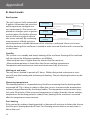
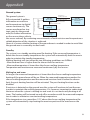
1
GB-DAS Installation and user manual DEVIreg™ 850 controller 1 Table of Contents 1: User Manual System overview . . . . . . . . . . . . . . . . . . . . . . . . . . . . . . . . . . . . . . . . . 3 General use . . . . . . . . . . . . . . . . . . . . . . . . . . . . . . . . . . . . . . . . . . . . . 5 Buttons . . . . . . . . . . . . . . . . . . . . . . . . . . . . . . . . . . . . . . . . . . . . 5 Display . . . . . . . . . . . . . . . . . . . . . . . . . . . . . . . . . . . . . . . . . . . . 5 Menu system . . . . . . . . . . . . . . . . . . . . . . . . . . . . . . . . . . . . . . . . 6 Possible alarms during operation Clogged drain . . . . . . . . . . . . . . . . . . . . . . . . . . . . . . . . . . . . . . . 7 Missing sensor . . . . . . . . . . . . . . . . . . . . . . . . . . . . . . . . . . . . . . . 7 New sensor added . . . . . . . . . . . . . . . . . . . . . . . . . . . . . . . . . . . . . 7 Sensor malfunction . . . . . . . . . . . . . . . . . . . . . . . . . . . . . . . . . . . . 7 Changing parameters and performance of systems . . . . . . . . . . . . . . . . . . . 8 Roof system . . . . . . . . . . . . . . . . . . . . . . . . . . . . . . . . . . . . . . . . . 8 Ground system . . . . . . . . . . . . . . . . . . . . . . . . . . . . . . . . . . . . . . . 9 2: Installer Manual System overview . . . . . . . . . . . . . . . . . . . . . . . . . . . . . . . . . . . . . . . . . 10 Placement . . . . . . . . . . . . . . . . . . . . . . . . . . . . . . . . . . . . . . . . . . . . . 11 Connection steps for system . . . . . . . . . . . . . . . . . . . . . . . . . . . . . . . . . 11 Installation steps for system/systems . . . . . . . . . . . . . . . . . . . . . . . . . . . . 15 General . . . . . . . . . . . . . . . . . . . . . . . . . . . . . . . . . . . . . . . . . . . 15 Installation of roof system . . . . . . . . . . . . . . . . . . . . . . . . . . . . . . . 16 Installation of ground system . . . . . . . . . . . . . . . . . . . . . . . . . . . . . 17 Installation of combi system . . . . . . . . . . . . . . . . . . . . . . . . . . . . . . 18 Installation of dual system . . . . . . . . . . . . . . . . . . . . . . . . . . . . . . . 20 Modification of system(s) . . . . . . . . . . . . . . . . . . . . . . . . . . . . . . . . . . . 22 Replacing a malfunctioning sensor . . . . . . . . . . . . . . . . . . . . . . . . . 23 Add an extra sensor . . . . . . . . . . . . . . . . . . . . . . . . . . . . . . . . . . . 24 3: Technical Specifications Technical data . . . . . . . . . . . . . . . . . . . . . . . . . . . . . . . . . . . . . . . . . . 25 Factory settings . . . . . . . . . . . . . . . . . . . . . . . . . . . . . . . . . . . . . . . . . . 26 4: Appendix A: Menu system . . . . . . . . . . . . . . . . . . . . . . . . . . . . . . . . . . . . . . . . . . 27 B: How it works . . . . . . . . . . . . . . . . . . . . . . . . . . . . . . . . . . . . . . . . . . 32 Roof system . . . . . . . . . . . . . . . . . . . . . . . . . . . . . . . . . . . . . . . . 32 Ground system . . . . . . . . . . . . . . . . . . . . . . . . . . . . . . . . . . . . . . 33 Security and energy consumption . . . . . . . . . . . . . . . . . . . . . . . . . . 35 C: PSU and feeder cable . . . . . . . . . . . . . . . . . . . . . . . . . . . . . . . . . . . . 36 Ground system . . . . . . . . . . . . . . . . . . . . . . . . . . . . . . . . . . . . . . 36 Roof system . . . . . . . . . . . . . . . . . . . . . . . . . . . . . . . . . . . . . . . . 36 2 User Manual System overview The DEVIreg™ 850 system is capable of keeping outdoor areas free of ice and snow. The DEVIreg™ 850 can handle up to 2 independent areas, in any of the following combinations: •S ingle roof system To keep gutters, valley gutters and down pipes free of ice and snow, and to prevent icicles from causing damage. It is also possible to use the roof system to reduce/remove the snow weight from a roof. (Roof system A) A •S ingle ground system To keep areas like parking areas, paths, garage entrances, steps, ramps, roadways and bridges free of ice and snow. (Ground systems A) A A •1 ground system and 1 roof system (combi system) Consists of 1 single roof system A and 1 single ground system B. A B B •2 roof systems (dual system) Consists of 2 x “Single roof systems (A and B)”. B A •2 ground systems (dual system) Consists of 2 x “Single ground systems (A and B)”. A B 3 User Manual When more than 1 area is controlled by the DEVIreg™ 850 system, it is also possible to prioritize the areas. Prioritizing makes it possible to operate 2 areas, even if the needed power for 2 areas is not present. The DEVIreg™ 850 is fully automatic and operated digitally by means of the intelligent sensors located in the heated terrain. Each sensor measures both temperature and moisture, and the system turns the heating elements on and off based on these readings. By combining moisture and temperature readings, the system is able to save around 75% energy compared to systems which only measure temperature readings. The digital sensors used for the DEVIreg™ 850 also provide the most exact readings when compared with corresponding analogue systems. The result is optimum functionality and low energy consumption. A typical installation consists of: •C ontroller unit (only one) This is the DEVIce which, based on the measurements from the sensors, decides when to heat the connected area(s). •P ower supply (one or more) The power supply delivers power to the controller unit and the connected sensors. •G round sensor (one or more) At least 1 ground sensor is needed for each ground area, but to get the best performance of a system, 2 or more sensors are recommended. For more information please refer to the sensor manual. • Roof sensor (one or more) At least 1 roof sensor is needed for each roof area, but for complex roof constructions, 2 or more sensors are recommended. For more information please refer to the sensor manual. For more information about the ice and snow melting function of the DEVIreg™ 850, please refer to: Appendix B: “How it works”. 4 User Manual General use The DEVIreg™ 850 is operated via 3 buttons and an alpha numeric display capable of displaying information in various languages. Buttons The functions of the 3 buttons are: Info Shows additional information / help (Only active when lit) Next Next menu entry / next line / next letter Enter Confirm / select Besides the normal function of the buttons, some special combinations are important to the user: Return to home of menu system: Hold for 2 seconds Master reset: Restore factory defaults AND delete installed systems (In case of insolvable problems due to a wrong choice of language, etc.) Hold + for 8 seconds Display The following icons have a special meaning: This animated icon is shown, when the system is heating. When the icon is blinking the system wants to heat, but is paused (system has low priority). T his icon is shown, when the system has detected moisture, and the temperature is above the melting temperature. T his icon is shown, when the system has detected snow or ice, and the temperature is below the melting temperature. The DEVIreg™ 850 can simultaneously control up to 2 different systems. These 2 systems are referred to as System A and System B. The DEVIreg™ 850 gives the user the opportunity to view the current status of the systems. The status can be shown in 2 different ways. 5 User Manual Combined view (default): The combined view shows the status of both systems at the same time. System A is shown on the upper display line, and System B is shown on the lower display line. This view gives the user a quick overview of all the systems. A:Roof B:Ground Flipped view: The flipped view shows the status of 1 system at a time. The status of each system is shown for 5 seconds. >Standby This view gives the user more detailed information about each system. >Melting The user can always press irrespective of view selected. A:Roof B:Ground to get more information about the current status Menu system The menu system is navigated by the keys No matter if the DEVIreg™ 850 controls one or two systems, the look and use of the menu system is always the same. This is obtained by making the entry to each system in the main menu. The possibilities and settings for each system are first accessible after the user has selected the desired system. and . 5s 5s To the right is given an example of the main menu and the menus for System A and System B. System A System B Only visible when System B is installed ! Please note, that only a few of the menus for each system are shown! For a complete overview of the menu system, please refer to Appendix A: “Menu system”. 6 User Manual Possible alarms during operation Clogged drain Description: When clogged drain warning has been enabled, an alarm is raised when the system constantly has been detecting moisture for 14 days. If the DEVIreg™ 850 controls more than 1 system, and prioritizing has been enabled, the time before clogged drain warning for the down-prioritized system, can be much longer. The time is only updated, when the system actually is allowed to heat the area (e.g. the up-prioritized system is not heating) Solution: - Check gutter and down pipes for any obstacles preventing the melting water to flow away. - Check if sensors are covered with dirt. Missing sensor Description: When the connection to a sensor is lost, the DEVIreg™ 850 alarms the user. At the same time the DEVIreg™ 850 automatically switches the system to “Constant Off” mode, and user interaction with the DEVIreg™ 850 is needed. Solution: - Acknowledge error and go to “Installer Site” in the menu system and select “Change System”. - Contact your local installer to get a replacement. New sensor added Description: When a new sensor is added, the DEVIreg™ 850 alarms the user and at the same time automatically switches to “Constant Off” mode. User interaction is needed in order to correct the error. Solution: Acknowledge error and go to “Installer Site” in the menu system and select “Change System”. Sensor malfunction Description: When something is wrong with the readings from connected sensors to the DEVIreg™ 850, an alarm is raised. Not all error prone sensors can be discovered using this feature! Solution: - Acknowledge error and go to “Installer Site” in the menu system and select “Change System”. - Contact your local service centre to get a replacement. 7 User Manual Changing parameters and performance of systems Several parameters for each system can be changed during and after the installation. For a complete understanding of how these parameters affect the performance of the roof and ground system, please refer to Appendix B: “How it works”. Only change the DEVIreg™ 850 parameters if you are aware of the effects of your actions. Reference: Appendix A: Installer menu Roof system Melting temperature Changing the melting temperature will affect when the system is activated in case of moisture and low temperatures. The factory setting is 1.5°C. This means that the heating system will be activated if the temperature falls below 1.5°C and moisture is detected. Moisture level The “moisture level” decides when the system detects moist. The factory setting is 50 (on a scale from 5 to 95). The lower the setting, the more sensitive the system is to moisture. Post-heat Once the sensor has detected that the roof/gutter is dry and free of ice and snow the system will keep heating for another hour (default). If you wish to increase/decrease this time see appendix A: Installer menu. The factory setting is 1 hour (on a scale from 0 to 9 hours) Priority When using the DEVIreg™ 850 as a dual or combi system, it is possible to prioritize the systems. When the priority of 2 systems is equal, both systems can heat at the same time. If the priority of the 2 systems differs, and both systems want to heat, only the system with the highest priority is allowed to heat. The factory setting is 1 (highest priority) for all systems. Clogged drain It is possible to enable and disable the “Clogged drain warning”. The factory setting is “Warning On”. System and sensor name It is possible to change the names of the system and connected sensors (see appendix A: Installer menu. 8 User Manual Ground system Melting temperature Changing the melting temperature will affect when the system is activated in case of moisture and low temperatures. The factory setting is 4°C. This means that the heating system will be activated if the temperature falls below 4°C and moisture is detected. Standby temperature (maintained ground temperature) The higher the standby temperature the faster the system will be able to melt ice and snow. On the other hand the higher the standby temperature the higher the running costs. So, determining the standby temperature is a trade-off between fast melting or low running costs. The factory setting is -3 C°. Moisture level The “moisture level” decides when the system detects moist. The factory setting is 50 (on a scale from 5 to 95). The lower the setting, the more sensitive the system is to moisture. Post-heat Once the sensor has detected that the roof/gutter is dry and free of ice and snow the system will keep heating for another hour (default). If you wish to increase/decrease this time see appendix A: Installer menu. The factory setting is 1 hour (on a scale from 0 to 9 hours) Priority When using the DEVIreg™ 850 as a dual or combi system, it is possible to prioritize the systems. When the priority of 2 systems is equal, both systems can heat at the same time. If the priority of the 2 systems differs, and both systems want to heat, only the system with the highest priority is allowed to heat. The factory setting is 1 (highest priority) for all systems. Clogged drain It is possible to enable and disable the “Clogged drain warning”. The factory setting is “Warning On”. System and sensor name It is possible to change the names of the system and connected sensors. 9 Installer Manual System overview The DEVIreg™ 850 can handle up to 2 independent areas, in any of the following combinations: • Single roof system (1 system, 1-4 roof sensors) • Single ground system (1 system, 1-4 roof sensors) • 1 ground system and 1 roof system (combi system) (2 systems, 2-4 sensors total, minimum 1 sensor per system) • 2 roof systems (dual system) (2 systems, 2-4 sensors total, minimum 1 sensor per system) • 2 ground systems (dual system) (2 systems, 2-4 sensors total, minimum 1 sensor per system) When more than 1 area is controlled by the DEVIreg™ 850 system, it is also possible to prioritize the areas. Prioritizing makes it possible to operate 2 areas, even if the needed power for 2 areas is not present. A typical ice and snow melting system consists of: • DEVIreg™ 850 Only 1 DEVIreg™ 850 is allowed on the DEVIbus™ • Power supply More power supplies can be connected in parallel (if needed) Be aware of maximum number of sensors on each power supply (Refer to Technical Specification for power demand of sensors) • Ground and/or roof sensor(s) Be aware of maximum number and cable length of sensors on each power supply (Refer to sensor manual for a more detailed description) 10 Installer Manual Placement The DEVIreg™ 850 and power supply are designed for DIN rail mounting. When mounting please be aware of the following conditions: The DEVIreg™ 850 is designed and approved to operate in the temperature range -10°C to 40°C. The DEVIreg™ 850 is only IP20 protected, thus not water resistant. The installer must ensure proper enclosure of the DEVIreg™ 850 according to national standards (electrical safety). Connection steps for system Only authorized personnel is allowed to install the DEVIreg™ 850. When wiring up the DEVIreg™ 850 and sensors, please be aware of the following conditions: When the DEVIreg™ 850 is used in a dual system configuration, it is preferable that each sensor bus (DEVIbus™) can be connected and disconnected via switches. During the installation of a dual system, each system must be connected one at a time. Be aware of maximum allowable power drain from power supply to sensors. Below is shown the recommended order of the installation. Please refer to figure A for connection of DEVIreg™ 850 and refer to figure B-G for a guideline to connect the heating elements to DEVIreg™ 850. 1. Connect heating cables to the DEVIreg™ 850 • Please notice that a single system ALWAYS uses the System A output relay • When using external power relay, please refer to the connection diagrams. 2. Connect the power supply to the DEVIreg™ 850 • Do not connect the power supply to mains yet 3. Connect sensors to the DEVIbus™ • When used as a dual system, only the sensors for System A can be connected. For connection of System B please refer to chapter: “Installation of dual system”. 4. Connect the power supply to mains. 11 Installer Manual DEVIbus sensors TM + - - Tx Rx GND White DC supply White White White Red Black Black DC output White White Red Black Red Sensor Sensor RS232 + 12 13 13 14 15 16 17 18 19 20 21 22 23 24 DC-PSU 24V/24W DEVIreg™ 850 PSU 24V NA 4 5 220 / 240V~ 50 - 60 Hz 1 2 3 4 5 6 7 8 9 10 11 12 ALARM System A System B 250V~2Aμ 250V~15Aμ 250V~15Aμ The DEVIreg™ 850 has an integral alarm function that monitors the attached sensors and the in-built microprocessor. An external alarm may also be connected to the system. 12 Installer Manual B - 230V, 1-3 P/1-3 loads - System A C - 230V, 1-3 P/1-3 loads - System B 230 V cables 230 V cables 13 Installer Manual D - 400 V, 2-3 Phase/1-3 Loads - System A E - 400 V, 2-3 Phase/1-3 Loads - System B 400 V cables 400 V cables F - Direct connection - System A G - Direct connection - System B 230 V cables 230 V cables 14 Installer Manual Installation steps for system/systems The installation of the DEVIreg™ 850 is very easy, and the user is guided through the installation process. The installation process differs a little depending on which kind and the number of systems to be installed. Please follow the general description and finally select the installation scenario according to the system type. Change setting with key: Accept setting with key: General Power on DEVIreg™ 850 Welcome to DEVIreg 850 III Select language Select language:English System is being checked… Select system configuration • Roof system (1 system) • Ground system (1 system) • Combi system (2 systems) • Dual system (2 systems) Checking system <‐‐‐‐‐‐‐‐> System size: 1 system The rest of the installation is divided into the system configurations; roof, ground, combi or dual, as listed above. 15 Installer Manual Installation of roof system The installation of a DEVIreg™ 850 with 1 roof system has been selected. It is optional if the sensors are connected to the DEVIreg™ 850 before power on or during the installation. The system uses the output System A. If sensors for System A are not connected - do it now! Press or wait… System is being scanned to find type of connected sensors… Connect sensors: System A System A Scanning... Select system type: Roof System type: Roof Wait until correct number of sensors for System A is found. 1 Roof sensor found. Accept? Press when all sensors are found… System A is installed… System A! Installed System is being checked… Checking system <‐‐‐‐‐‐> Press to configure System A (naming sensors and changing factory settings). Config system: System A Please refer to “Changing parameters and performance of systems” in “User Manual” for description of the configurable parameters. If for some reason you do not wish to configure the system now you can press skip configuration of system . Press 16 to end configuration. Press to end configuration. to Installer Manual Installation of ground system The installation of a DEVIreg™ 850 with 1 ground system has been selected. It is optional if the sensors are connected to the DEVIreg™ 850 before power on or during the installation. The system uses the output System A. If sensors for System A are not connected - do it now! Press or wait… System is being scanned to find type of connected sensors… Connect sensors: System A System A Scanning... Select system type: Ground. System type: Ground Wait until correct number of sensors for System A is found. 3 Ground sensor found. Accept? Press when all sensors are found… System A is installed… System A! Installed System is being checked… Press to configure System A (naming sensors and changing factory settings). Checking system <‐‐‐‐‐‐> Config system: System A Please refer to “Changing parameters and performance of systems” in “User Manual” for description of the configurable parameters. If for some reason you do not wish to configure the system now you can press skip configuration of system . Press to end configuration. to Press to end configuration. 17 Installer Manual Installation of combi system The installation of a DEVIreg™ 850 with 1 roof and 1 ground system has been selected. It is optional if the sensors are connected to the DEVIreg™ 850 before power on or during the installation. The first installed system (System A) is using the output System A. The second installed system (System B) is using the output System B. It is freely selectable if System A should be the roof or ground system. However it is preferable that System A is the roof system, since System A is shown on the upper line of the display. Please refer to the description of the Display and Combined view in the user manual. If sensors for System A are not connected - do it now! Press or wait… System is being scanned to find type of connected sensors… System A Scanning... Select system type: Roof (if roof system is preferred as System A) System type: Roof Wait until correct number of sensors for System A is found. 1 Roof sensor found. Accept? Press when all sensors are found… System A is installed… System A! Installed If sensors for System B are not connected - do it now! Press or wait… System is being scanned to find type of connected sensors… Wait until correct number of sensors for System B is found. Press 18 Connect sensors: System A when all sensors for System B are found… Connect sensors: System B System B Scanning... System type: Ground 3 Ground sensors found. Accept? Installer Manual Press when all sensors for System B are found… System B is installed… System B! Installed System is being checked… Checking system <‐‐‐‐‐‐> Press to select system to configure. Press to configure selected system (naming sensors, changing factory settings and setting priorities.) Config system: System A Config system: System B Please refer to “Changing parameters and performance of systems” in “User Manual” for description of the configurable parameters. Press to end configuration. Press to end configuration. 19 Installer Manual Installation of dual system The installation of a DEVIreg™ 850 with 2 roof systems or 2 ground systems has been selected. It is mandatory that no sensors or only sensors for System A are connected to the the DEVIreg™ 850 before power up. Sensors for System B must be connected to the DEVIreg™ 850 during the installation steps. Connection of the sensors during installation can either be done using a switch on the DIN-rail or just connect sensor bus of System B to the already connected sensor bus of System A. The first installed system (System A) is using the output System A. The second installed system (System B) is using the output System B. If sensors for System A are not connected - do it now! Press or wait… System is being scanned to find type of connected sensors… System A Scanning... Select system type: Ground. System type: Ground Wait until correct number of sensors for System A is found. 1 Ground sensor found. Accept? Press when all sensors for System A are found… System A is installed… System A! Installed Connect sensors for System B. Press or wait… System is being scanned to find type of connected sensors… 20 Connect sensors: System A Connect sensors: System B System B Scanning... Select system type. System type: Ground Wait until correct number of sensors for System B is found. 1 Ground sensor found. Accept? Installer Manual Press when all sensors for System B are found… System B is installed… System B! Installed System is being checked… Checking system <‐‐‐‐‐‐> Press to select system to configure. Press to configure selected system (naming sensors, changing factory settings and setting priorities.) Config system: System A Config system: System B Please refer to “Changing parameters and performance of systems” in “User Manual” for description of the configurable parameters. Press to end configuration. Press to end configuration. 21 Installer Manual Modification of system(s) It is possible to modify the installed systems on the DEVIreg™ 850. The following modifications are possible: • Reactivate passive sensors • Replace a malfunctioning sensor • Add an extra sensor When the DEVIreg™ 850 cannot communicate with a sensor, the DEVIreg™ 850 reports the error: “Errors detected!”. The DEVIreg™ 850 does not rely on malfunctioning sensors, and therefore the DEVIreg™ 850 makes the sensor passive. The passive sensor is no longer used for ice and snow detection - not even after a power cycle. If the malfunctioning is caused by problems with the wiring, the failure can be fixed, and the sensor can be reactivated. If the malfunctioning is caused by an error prone sensor, the error can be corrected by replacing the error prone sensor with a new sensor. It is not possible to delete a passive sensor in a system. Passive sensors will remain in the systems until they are replaced with new sensors. The only way to delete a passive sensor (other than replacing it), is to make a Master Reset and reinstall the DEVIreg™ 850 (please refer to chapter: General use). Reactivate passive sensors: The given example is for a ground system. From the installer menu select Change system. Press Change system to activate Change system. The system is searching for connected sensors. Checking system <‐‐‐‐‐‐‐> If any passive sensors are found, they are reactivated. Message is shown for 3 seconds. 1 sensor(s) reactivated! If no new sensors are found, it is reported to the user. Message is shown for 3 seconds. No ground sensors found! 22 Installer Manual Replacing a malfunctioning sensor From the installer menu select Change system. The system is searching for connected sensors. The user selects the passive sensor, which should be replaced with a new one. Press to loop through the found passive sensors or to cancel replace sensor. Press when the correct passive sensor or “Cancel replace sensor?” is selected. If the user selected a passive sensor to replace, the user should now select the new sensor. Press to loop through the found new sensors or to cancel replace sensor. Checking system <‐‐‐‐‐‐‐> Replace sensor: Sensor1 03FB2F Replace sensor: Sensor2 03FC24 Cancel replace sensor? Add sensor: ID: 03ABC1 Add sensor: ID: 03DEF1 Press when the correct new sensor to add is found or “Cancel replace sensor?” is selected. Cancel replace sensor? If the user selected a new sensor to add, the replacing of the sensors is performed. Sensor replaced! Add an extra sensor: From the installer menu select Change system. The system is searching for connected sensors. Press to loop through the found passive sensors or to cancel replace sensor. Press when the correct new sensor to add is found or “Cancel add sensor?” is selected. Checking system <‐‐‐‐‐‐‐> Add sensor: ID: 03ABC1 Cancel add sensor? 23 Installer Manual Add an extra sensor From the installer menu select Change system. The system is searching for connected sensors. Press to loop through the found passive sensors or to cancel replace sensor. Press when the correct new sensor to add is found or “Cancel add sensor?” is selected. If the user selected a new sensor to add, the sensor is added. 24 Checking system <‐‐‐‐‐‐‐> Add sensor: ID: 03ABC1 Cancel add sensor? Sensor added! Technical Specifications Technical data Voltage: • DEVIreg™ 850 • Power supply 18-26 VDC 180-250 VAC, 50/60 Hz Power consumption: • DEVIreg™ 850 • Roof sensor(s) • Ground sensor(s) Max. 3 W Max. 8W (each) Max. 13W (each) Relay load capability: • Resistive load Alarm realy • Resistive load System A relay • Resistive load System B relay • Inductive load each realy 230V ~ 2A 230V ~ 15A 230V ~ 15A 1A (power factor 0.3) IP class: • DEVIreg™ 850 • Roof sensor(s) • Ground sensor(s) IP 20 IP 67 IP 67 * * Ambient temperature: • DEVIreg™ 850 • Roof sensor(s) • Ground sensor(s) -10°C to +40°C -50°C to +70°C -30°C to +70°C * * Sensor type: DEVIbus™ connected moisture sensor(s) Indication: 2 x 16-character illuminated display Alarm light (red) Lit info key (yellow) Measurements: • DEVIreg™ 850 • Roof sensor(s) • Ground sensor(s) • Tube ground sensor(s) (Depth x Height x Width) 53 mm x 86 mm x 105 mm 15 mm x 23,5 mm x 216 mm * D = 87 mm; height = 74 mm * D = 93 mm; height = 98 mm * Type: • DEVIreg™ 850 D850 DP-10 * * * For further information on the sensors please refer to the sensor manual. 25 Technical Specifications Factory settings Roof System Function Factory settings Range/Options Moisture level 50 5 to 95 (5 being the most sensitive to moisture) Melting temperature 1.5°C 0.0°C to 9.9°C Post-heat 1 hour 0 to 9 hours Clogged drain On On/off System mode Automatic • Automatic • Constant ON (manual timer) • Manually OFF Function Factory settings Range/Options Moisture level 50 5 to 95 (5 being the most sensitive to moisture) Standby temperature -3.0°C -20°C to 0°C Melting temperature 4.0°C 1.0°C to 9.9°C Post-heat 1 hour 0 to 9 hours Clogged drain On On/off System mode Automatic • Automatic • Constant ON (manual timer) • Manually OFF Ground system 26 Appendix A A: Menu system Main menu 5s 5s System A System B Only visible when System B is installed ! System menu System menu (A / B) Return to main Installer menu 27 Appendix A View sensor measurements View sensor measurements (Roof systems) View system parameters (Roof system) View sensor parameters View sensor measurements (Ground system) View system parameters (Ground system) 28 Appendix A Installer menu Installer menu _ - Change system View statistics 29 Appendix A Change system Change system If no new sensor(s) found (Example showing ground system). Only if any passive (disabled) sensors are working again! If new sensor(s) found, but no passive sensor(s) found. If new sensor(s) found and passive sensor(s) found. 30 Appendix A View statistic View statistics 31 Appendix B B: How it works Roof system The roof system is fully automated. Standby (No heating) It gathers information on moisture Temperature > Temperature < Melting temperature Melting temperature and temperature via digital senand Moisture > Moisture limit Measuring sors continuously. The sensors are After 3 hours Melting temperature 0-20 minutes (Heating) (No heating) placed on strategic spots in gutters or down pipes (for further informaMoisture < Moisture limit tion on the sensor please refer to Post-heating Post-heating time elapsed the sensor manual). By combining (Heating) measurements of both moisture and temperature a reliable detection of the situation is achieved. Hence it is known whether heating of the roof area is needed in order to avoid that the roof is covered by ice and snow. Standby The system is on standby and awaits heating of the roof area. Heating of the roof area will start when the following conditions are fulfilled: • Measured moisture is higher than the chosen limit for moisture. • Measured temperature is lower than the chosen melting temperature Temperature and moisture are measured continuously by the sensors. Melting ice and snow The roof area is heated in periods of 3 hours. Within that period a decrease in moisture will stop the heating and activate post-heating. The post-heating function can be disabled. Measuring temperature The heating function is suspended every third hour meaning that the heating cables are turned off. This is done in order to allow the sensors to measure the temperature, without being influenced by the heated cables. The temperature measurement may last up to 20 minutes. If the measured temperature is higher than the chosen melting temperature the heating period is ended; if not, heating of the roof area is resumed after the temperature measurement. Post-heating If the reason for ending a heating period is a decrease of moisture to below the chosen level the post-heating period will start. Post-heating ensures that no ice and snow is left on the roof. 32 Appendix B Ground system Temperature < Temperature > Melting temperature + 1.5 ˚C Poat-heat time elapsed Standby temperature The ground system is Temperature >Standby Standby Standby temperature fully automated. It gathers (No heating) Mantaining standby temperature Temperature < Melting temperature information on moisture (Heating) and Moisture > Moisture limit and temperature via digital Melting sensors continuously. The (Heating) sensors are placed on straMoisture < Moisture limit tegic spots on the ground Post-heating area (for further information (Heating) on the sensor please refer to the sensor manual). By combining measurements of both moisture and temperature a reliable detection of the situation is achieved. Hence it is known whether heating of the ground area is needed in order to avoid that the ground area is covered by ice and snow. Standby The system is on standby awaiting need for heating. If the measured temperature is below the chosen standby temperature the system will automatically heat the area in order to maintain the standby temperature. Melting (heating) will start when the two following conditions are fulfilled: • Measured moisture is higher than the chosen limit for moisture. • Measured temperature is lower than the chosen melting temperature Temperature and moisture are measured continuously by the sensors. Melting Ice and snow As long as the measured temperature is lower than the chosen melting temperature heating of the ground area will be on. When the measured temperature reaches the chosen melting temperature and the measured moisture level is below the chosen limit, the post-heating function will be activated. The post-heating function can be disabled. If moisture is detected on the ground area the system will continue to heat the area in order to maintain the melting temperature. It is, however, important to understand that even when the system is melting ice and snow it is not necessarily heating at all times. The heating will be turned on and off in accordance with the measured temperature in order to maintain a constant melting temperature. If the temperature rises more than 1.5°C above the chosen melting temperature the system will automatically stop heating the area irrespective of the moisture on the area. 33 Appendix B Post-heating If the reason for ending a heating period is a decrease of moisture to below the chosen level, the post-heating period will start. Post-heating ensures that no ice and snow is left on the roof. If system priority is low, heating might be paused at any time! The ground system uses heated sensors which under normal circumstances will hold a temperature of 1.5°C. In connection with measuring the area temperature heating of the sensor is turned off for 90 minutes at a time. This is done in order to obtain a correct measurement of area temperature which is not influenced by sensor temperature. If a system only has one sensor this sensor is constantly heated for 90 minutes and then turned off for 90 minutes. This entails that measurement of temperature can be up to 3 hours delayed. With more than one sensor this performance is significantly improved. 34 Appendix B Security and energy consumption High security – higher energy consumption If a high degree of security against ice and snow is wanted, make the following adjustments of the operation parameters: • Increase the standby temperature • Increase the melting temperature • Decrease the moisture level (close to setting 5) • Prolong the post-heat period This will give a high degree of security in even dry areas. Low security – lower energy consumption Conversely, low energy consumption and a moderate level of security against ice and snow could be prioritized. In this case make the following adjustments of the operation parameters: • Decrease the standby temperature • Decrease the melting temperature • Increase the moisture level • Shorten the post-heat period This will give relatively low energy consumption, but the area may remain wet and icy in short periods. T he factory settings are average values providing a relatively high degree of security and moderate energy consumption. 35 Appendix C C: PSU and feeder cable Ground system 1 pcs. PSU 24 VDC 24 W 2 pcs. PSU 24VDC, 24 W in parallel Number of sensors: 1 or 2 * 3 4 Cable type Max. length (m) Max. length (m) Max length (m) 1 mm² 300 150 80 1.5 mm² 450 225 120 2.5 mm² 750 360 200 4 mm² 1200 600 310 *if 2 sensors are used in a dual zone system (ie. 1 sensor in each zone) - 2 PSUs are required Roof System 1 pcs. PSU 24 VDC 24 W 2 pcs. PSU 24VDC, 24 W in parallel Number of sensors: 1 2 3 4 Cable type Max. length (m) Max. length (m) Max. length (m) Max length (m) 1 mm² 400 100 130 75 1.5 mm² 600 150 200 110 2.5 mm² 1000 250 330 190 4 mm² 1600 400 525 300 36 37 The DEVI TM Guarantee You have purchased a DEVI heating system which we are sure will serve to improve the comfort and economy of your home. DEVI provides a complete heating solution with DEVIflexTM heating cables or DEVImatTM heating mats, DEVIregTM thermostats and DEVIfastTM fixing strips. Should you, against all expectations, experience a problem with your DEVI heating system, you will find that DEVI, whose products are manufactured in Denmark and sold throughout the European Union, is subject to the standard regulations pertaining to product liability as specified in EU directive 85/374/CEE as well as all applicable legislation in the individual countries on the following conditions: DEVI offers a 10-year guarantee on all DEVIflexTM heating cables and DEVImatTM heating mats, and a 2-year guarantee against material defects and production defects in connection with any other DEVI products. case of faulty DEVIregTM thermostats, DEVI reserves the right to repair the unit free of charge and without any unreasonable delays for the customer. The guarantee shall be valid only if the GUARANTEE CERTIFICATE is completed correctly and in accordance with the instructions, and provided the fault is inspected by or submitted to DEVI or an authorised DEVI dealer. The above guarantee covers product liability only, while purchases are subject to national legislation. Please note that the GUARANTEE CERTIFICATE must be completed in English or local language. DEVI shall undertake any repair free of charge or supply the customer with a new unit. Repairs shall be carried out at no further cost to the customer. In the 38 The DEVI Guarantee shall not cover installations that have been carried out by non-authorised electricians, faults which arise as a result of misuse by other suppliers, damage caused by third parties, incorrect installations or consequential damage. All work will be invoiced in full if DEVI is required to inspect or repair faults that have arisen as a result of any of the above. The DEVI Guarantee shall not extend to equipment which has not been paid in full. DEVI will, at all times, provide a rapid, effective and honest response to all queries and reasonable demands from our customers. The DEVI TM Guarantee Guarantee Certificate The DEVI™ Guarantee is granted to: Name: Address: Postal code: Phone: Please observe! In order to obtain the DEVITM Guarantee, the following must be carefully filled in. See other conditions on previous page. Electrical Installation by: Installation date: Type of thermostat: Production code: Suppliers Stamp: DEVI A/S DK • 7100 Vejle Phone +45 76 42 47 00 Fax +45 76 42 47 03 39 VICKM402 01/2013 Article: 08095387 ˚C