1
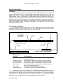
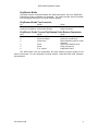
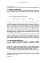
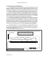
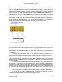
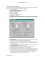
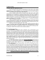
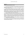
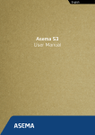
2PEA-1000
2PEA-1000/F
PolyElectric Probes
Mount Sopris Instrument Co., Inc.
Golden, CO U. S. A.
January 30, 2004
Table of Contents
General Information..................................................................................................................... 3
Overview......................................................................................................................... 3
Connectors and Layout .................................................................................................. 3
Theory of Operation..................................................................................................................... 5
Normal Resistivity Measurements .................................................................................. 5
Single Point Resistance Measurement .......................................................................... 5
SP measurement............................................................................................................ 6
Fluid Resistivity Measurement........................................................................................ 6
Fluid Temperature Measurement ................................................................................... 6
Natural Gamma Radiation Measurement....................................................................... 6
Derived Measurements .................................................................................................. 6
Specifications.................................................................................................................. 7
Installation.................................................................................................................................... 8
Installing the PolyElectric Probe ..................................................................................... 8
Operating Procedure ................................................................................................................... 9
Operation ........................................................................................................................ 9
Performance Checks and Calibrations........................................................................... 11
Preventative Maintenance .............................................................................................. 14
Troubleshooting ........................................................................................................................... 15
Problems with the PolyElectric Probe ............................................................................ 15
Disassembly Instructions................................................................................................ 15
Schematics .................................................................................................................................. 16
Appendix...................................................................................................................................... 17
Suggested Quality Assurance Procedure ...................................................................... 17
2PEA-1000 PolyElectric Probe
General Information
Overview
The 2PEA-1000 PolyElectric probe and the 2PGA-1000 PolyGamma probe combine to
make a multi-parameter probe. The totally digital probe combination measures 8, 16, 32, and
64inch (0.2, 0.4, 0.8, 1.6 meter) normal resistivity, single point resistance, self-potential, and
natural gamma. When is configured as a 2PEA-1000/F PolyElectric probe and used with the
2PGA-1000 PolyGamma probe, fluid resistivity and fluid temperature are also measured in
addition to the above listed parameters. These probe combinations operate with the MGX II
series portable digital logger or the Series V digital logger. The normal resistivity measurements,
single point resistance, and self-potential measurements are designed for surveying open
(uncased) fluid filled boreholes.
Connectors and Layout
The function of each electrode is listed below, starting with the bottom electrode and
proceeding towards the top of the probe. For more information on the function of these
electrodes, consult the Theory of Operation section of this document.
PolyElectric /
PolyGamma
Connector
A
M32
M16
Cable
M64 Electrode
M8
Bridle
PolyElectric/ PolyGamma Probe
Logging Cable
Electrodes:
Electrode
Bottom electrode
Second from bottom
Third from bottom
Fourth from bottom
Top electrode
Cable Armor
Surface Electrode
Functional Name
‘A’ electrode or Current Electrode, and ‘R’: single point
resistance electrode
‘M8’ electrode: 8inch normal resistivity measure electrode
‘M16’ electrode: 16inch normal resistivity measure electrode
‘M32’ electrode: 32inch normal resistivity measure electrode
‘M64’ electrode: 64inch normal resistivity measure electrode;
and ‘SP’: self potential electrode
‘N’ electrode: measure reference electrode
‘B’ electrode: current return electrode (Mudplug)
Connectors for the tool are as follows. The PolyGamma probe top described below is a
Mount Sopris standard single conductor probe top. Other variations of probe tops and wiring can
be ordered from the factory but will not be discussed in this document. The connector between
the PolyElectric and PolyGamma probes is a ring style connector. The numbering of the rings
begins from the inner most ring (ring 1) and proceeds to the outer ring (ring 6).
P/N 7000-0119D
3
2PEA-1000 PolyElectric Probe
PolyElectric Bridle
The bridle must be connected between the cable head and the top of the PolyElectric PolyGamma Probe combination as illustrated. The bridle provides electrical isolation
from the logging cable armor for normal resistivity logging.
PolyGamma Probe Top Connector:
Pin
Signal
Probe top housing
Probe power ground
Center pin in probe top Probe power positive
Origin
Armor
Center conductor
PolyElectric Probe Top and PolyGamma Probe Bottom Connectors:
Ring
1
2
3
Signal
SP, R or 64" Normal
Center conductor
Pulse return
4
5
6
Pulse
Armor
P. S. Control
Origin
Electrode below probe top
Center pin on probe top
Returns Gamma pulse to center
conductor
Output from Gamma circuit
Armor of probe top
PolyElectric Probe
The 2PEA-1000/F has fluid temperature and fluid resistivity sensors located on the
bottom of the probe. For more information on these sensors, consult the 2SFA-1000, PolyAgua,
documentation.
P/N 7000-0119D
4
2PEA-1000 PolyElectric Probe
Theory of Operation
Normal Resistivity Measurements
The normal resistivity and single point resistance measurements are accomplished by
measuring the amount of survey current that the logger and probe produce between the ‘A’
electrode and the mudplug (or armor during the ‘normal resistivity using armor’ operational
mode). A voltage is measured for each resistance or resistivity channel. All voltage
measurements are made with respect to the armor. The quotient between the voltage and
current for each channel is used to calculate the reported value.
For the normal resistivity measurements, Ohm’s law can be written,
ρ ⋅l
V
=R=
I
A
or
ρ=
A⋅V
l ⋅I
or
ρ = G⋅
V
I
where ρ is resistivity (ohm-meters), R is resistance (ohms), l is the distance the survey current
travels (meters), A is the cross sectional area that the current travels through (meters2), V is
voltage (volts), and I is current (amps). The quantity (A/l) is called the geometric factor G
(meters). The geometric factor is approximately 12.5 times the ‘AM’ spacing, in meters. The
survey current leaves the ‘A’ electrode in all directions, diverging as it does so. In a homogenous
medium, concentric spheres centered around the ‘A’ electrode, and with radius ‘AM’, delineate
the volume of investigation for the normal resistivity measurement. ‘AM’ refers to the distance
between the ‘A’ and ‘M’ electrodes. The volume of investigation (in a homogenous medium) for
the 8 inch normal resistivity measurement is a sphere with an 8 inch radius; the volume of
investigation for the 64 inch normal resistivity measurement is a sphere with a 64 inch radius.
These spheres are called equipotential surfaces. The voltage is measured between an
equipotential surface (sphere surrounding the volume of investigation) and the reference (armor).
This voltage is divided by the measured value of the survey current, and the result multiplied by
the geometric factor to obtain resistivity.
The normal resistivity circuits report the average resistivity of the material in the volume
of investigation and the volume of investigation may vary for heterogeneous mediums.
Therefore, the measured resistivity is called the apparent resistivity. Many computer programs
are available to convert apparent resistivity to true resistivity. These programs usually require a
geologic model and the apparent resistivity data to calculate true resistivity. Some programs
calculate synthetic logs such as invasion profile, synthetic focused resistivity logs, and porosity
logs.
Single Point Resistance Measurement
Refer to Ohm’s law from above for the explanation of the single point resistance
measurement. As the survey current leaves the ‘A’ electrode, the current diverges, and the cross
sectional area A through which it travels becomes very large compared to l. The quantity (l/A) in
the first equation approaches zero as the distance from the ‘A’ electrode increases. Therefore
most of the measured resistance is a result of the survey current near the ‘A’ electrode and also
at the mudplug where the current converges. The resistance indicated by the single point
resistance circuit, is the sum if the resistance near the mudplug, and the resistance near the ‘A’
electrode. Since the resistance near the mudplug does not change, any excursion indicated in
the single point resistance log is a result of the change in resistance near the ‘A’ electrode.
When the PolyElectric - PolyGamma probe combination is operated in ‘R-SP’ mode (see
the Operating Procedure section of this document), the current generator and all measure circuits
are contained in the logger at the surface. The mudplug is used as the current return (‘B’) and
reference (‘N’) electrodes. The top electrode on the probe functions as the current (‘A’) and
measure (‘M’) electrodes. In this mode, the top electrode on the probe is connected to the cable
line center conductor. Since the probe requires no power, this mode of operation is sometimes
referred to as the ‘passive’ mode.
P/N 7000-0119D
5
2PEA-1000 PolyElectric Probe
SP measurement
The SP (self potential) circuits measure the DC (direct current) voltage between the top
electrode on the probe and the armor. The resistivity circuits utilize an AC (alternating current)
survey current so that the SP circuits are not affected.
When the PolyElectric - PolyGamma probe combination is operated in ‘R-SP’ mode, the
current generator and all measure circuits are contained in the logger at the surface. The
mudplug is used as the current return (‘B’) and reference (‘N’) electrodes. The top electrode on
the probe functions as the current (‘A’) and measure (‘M’) electrodes. In this mode, the top
electrode on the probe is connected to the cable line center conductor. Since the probe requires
no power, this mode of operation is sometimes referred to as the ‘passive’ mode. This mode may
give better SP log results near the water level in the borehole.
Fluid Resistivity Measurement
The fluid resistivity measurement generates a survey current between small current (‘A’
and ‘B’) electrodes located inside the survey tube. Small measure (‘M’ and ‘N’) electrodes,
located between the current electrodes, are used to measure the potential difference generated in
the fluid by the current electrodes. The process is identical to that of the normal resistivity
measurements, except that the volume of investigation is entirely contained in the survey tube.
Fluid Temperature Measurement
The fluid temperature measurement uses a solid-state temperature-sensing device. The
electrical output of this device is proportional to the temperature of the fluid. The thermal mass of
the temperature sensor is kept as low as practical so that the time required for the sensor to
respond to a change in temperature is minimal.
Natural Gamma Radiation Measurement
For details on operation of the natural gamma sensor, consult the PolyGamma manual.
Derived Measurements
Measurements from the PolyElectric probe can be combined to make derived quantities.
Lateral resistivity logs and synthetic LL7 logs can be obtained from normal resistivity logs. Mud
invasion profiles can be determined with multiple spaced resistivity logs. These profiles illustrate
rock permeability. Mud resistivity can be calculated from the fluid resistivity. Mud resistivity can
then be used to calculate porosity. Many of these calculated measurements can be made in real
time while logging the data. For more information about these and other derived measurements,
consult Mt. Sopris Instrument Co.
P/N 7000-0119D
6
2PEA-1000 PolyElectric Probe
Specifications
Length 2PEA-1000 .............................................. 74 inches (188 cm)
Length 2PEA-1000/F ........................................... 87 inches (221 cm)
Diameter .............................................................. 1.55 inches (40 mm)
Weight 2PEA-1000 .............................................. 16 lbs. (7.3 Kg)
Weight 2PEA-1000/F........................................... 22 lbs. (10 Kg)
Operating Temperature ....................................... 0 to 70 degrees C
Storage Temperature .......................................... -40 to 125 degrees C
Maximum Pressure.............................................. 2000 psi (13.8 Pa)
Low Range Normal Resistivity Measurement ..... 0 to 250 ohm-meters
High Range Normal Resistivity Measurement..... 0 to 2500 ohm-meters
Normal Resistivity Accuracy ................................ 1 %
Normal Resistivity Resolution.............................. 0.02 %
Low Range Single Point Resistance Measurement
0 to 500 ohms
High Range Single Point Resistance Measurement
0 to 5000 ohms
Single Point Resistance Accuracy....................... 1 %
Single Point Resistance Resolution .................... 0.02 %
Self Potential Measurement Range..................... -1.5 to 1.5 VDC
Self Potential Measurement Accuracy ................ 1 %
Self Potential Measurement Resolution .............. 0.04 %
Fluid Resistivity Measurement Range................. 0-100 ohm-meters
Fluid Resistivity Accuracy.................................... 1 %
Fluid Resistivity Resolution.................................. 0.02 %
Fluid Temperature Measurement Range ............ -20 to 70 degrees C
Fluid Temperature Accuracy ............................... 0.5 %
Fluid Temperature Resolution ............................. 0.05 %
P/N 7000-0119D
7
2PEA-1000 PolyElectric Probe
Installation
Installing the PolyElectric Probe
The PolyElectric probe, PolyGamma probe, and the isolation bridle must be assembled
before logging. Consult the Operating Procedure section of this manual for specific information.
The most common reason for failure of a logging probe is mechanical damage. Often
this occurs in transportation. The only installation requirement is to provide a safe place for the
probe during transportation and storage. Despite efforts to make logging probes as rugged as
possible, they are still fragile instruments; they need to be protected.
A software driver for the probe must be installed on the PC for the acquisition software to
operate with the PolyElectric - PolyGamma probe combination. Consult the software instruction
manual for specific instructions.
P/N 7000-0119D
8
2PEA-1000 PolyElectric Probe
Operating Procedure
Operation
There are three modes of operation for the PolyElectric - PolyGamma probe combination.
The first is the ‘low range normal resistivity mode’. The normal resistivity range of
measurement for this mode is 0 to 250 ohm-m. This is the most common and recommended
mode of operation. All measurements are made in this mode. The normal resistivity
measurements will operate properly when the probe is lowered to a depth where the exposed
armor is submerged in the borehole fluid. This mode uses the armor as the SP reference; there
may be some drift in the SP measurement until approximately 100 feet (30 meters) of exposed
armor is below water level. Use the ‘R-SP mode’ if this is a problem. This mode requires the
use of the isolation bridle.
The second mode of operation is the ‘high range normal resistivity mode’. The normal
resistivity range of measurement for this mode is 0 to 2500 ohm-m. All measurements are made
in this mode. The normal resistivity measurements will operate properly when the probe is
lowered to a depth where the exposed armor is submerged in the borehole fluid. This mode uses
the armor as the SP reference; there may be some drift in the SP measurement until
approximately 100 feet (30 meters) of exposed armor is below water level. Use the ‘R-SP mode’
if this is a problem. This mode requires the use of the isolation bridle.
The third mode of operation is the ‘R-SP mode’. Only single point resistance and self
potential are measured in this mode. The top electrode is used to make SP and single point
resistance measurements. Since this mode does not put any voltages on any electrodes that
might interfere with SP measurements, it is the best mode to use when SP is the primary log of
interest.
The first step in the operation of the PolyElectric - PolyGamma probe combination is to
connect the probe to the cable head. Make sure probe power is off before disconnecting or
connecting the cable head. The current data acquisition software will control this from the PC.
Unscrew the cable head thread protector and the probe top thread protector. Screw the two
protectors together to keep dirt out of the threads and off of the ‘O’ ring surfaces. Make sure that
the threads and ‘O’ ring surfaces on the cable head and the probe top are clean and the ‘O’ ring
is properly lubricated. Thread the cable head into the isolation bridle. Hand tighten. Connect the
other end of the isolation bridle to the probe top. If the ‘R-SP mode’ is used, then the cable head
can be connected directly to the probe top. Use PVC electrical tape to tightly tape up all exposed
metal parts on the probe top, cable head, and lower part of the isolation bridle. Make sure that
there are no breaks in the electrical insulation anywhere on the probe except the electrodes.
It is very important that the mudplug be effectively ‘planted’. The object is to create
a good electrical coupling with the ground. The mudplug should be located at least 25 feet (8
meters) from the borehole. The preferred method is to dig to moist ground, plant the mudplug in
the moist ground, saturate the area with water, and then add a shovel full of dirt. If it is not
possible to dig to moist ground, try to find a water pipe or an electrical conduit running into the
ground to connect the mudplug to. Mudpits created by drilling make ideal places to plant the
mudplug. In the event that none of the above methods are obtainable, dig into the ground, plant
the mudplug, and pour as much water as practical on the mudplug, and then add a shovel full of
dirt. In dry conditions, a long rod driven into the ground may give good results. The green
banana jack on the logger is the mudplug connector.
The logger and winch must be electrically isolated from any utility power source
that utilizes earth ground. This means that the body of the winch cannot be in contact with
anything powered from the public power grid. If the logger is not isolated from the power grid, no
risk of electrocution is present; but the resulting logs may be low quality. Power for the logger
can be obtained from a generator or a DC to AC inverter.
It is sometimes possible to obtain resistivity logs at shallow depths where the exposed
section of the armor is above water level in the borehole. This requires a second surface
electrode be connected to the armor banana jack on the logger. This is the black banana jack.
The second surface electrode must be ‘planted’ at least 25 ft. (8 meters) from the mudplug
electrode. Often, the second surface electrode is placed near the borehole; steel casing works
P/N 7000-0119D
9
2PEA-1000 PolyElectric Probe
well as the second electrode. The mudplug electrode should be placed far from the borehole.
Effective ‘planting’ of the electrodes becomes much more important when trying to obtain shallow
normal resistivity logs. Sometimes, a shift in the resistivity values will occur as the exposed
armor is raised above water level. Changing the position of the surface electrodes may help in
this situation.
Log the probe as indicated by the instructions below. Consult the MSLog user
documentation for the acquisition software for further information.
Logging Instructions for MSLog
1.
Select the correct tool driver from the Tool panel selection box. If the correct one is not
available, run MSLConfig to install it.
2.
In the Tool panel, click the Power On button. It is advisable to power the probe while
it is in the hole for a few minutes to warm up the electronics before logging for
optimum accuracy.
3.
Place the tool in the borehole and position the top of the tool at the zero depth point.
Click the Depth panel upper right corner icon. Click Zero Tool. If you can not place the
tool top at depth reference (perhaps the bridle will not go through a sheave), press the
Change Depth button and enter the depth of the bottom of the tool.
4.
If you wish to fill out the header, in the Acquisition panel click Header button.
5.
In the Acquisition panel, click Record and select a file name.
6.
Place the probe at the beginning of the interval to be logged. Usually, this is the bottom
of the well because most logs are run from bottom to top for better depth control.
7.
Turn on the desired, Depth Sampling mode.
8.
If you are printing, turn on the printer in MCHCurve.
9.
Log to the desired interval as normal. Refer to the MSLog manual for additional
information on logging.
10.
When done, in the Acquisition panel, click Stop.
11.
In the Tool panel, click the Power Off button before removing the probe.
P/N 7000-0119D
10
2PEA-1000 PolyElectric Probe
Performance Checks and Calibrations
The PolyElectric probe has been calibrated at the factory and should require no field
calibration. The calibration parameters are stored in computer memory inside the probe. If small
changes in calibration are required, the acquisition software provides the means to do this. If
large changes in calibrations are necessary, it is advisable that the probe be sent to the factory
for evaluation and calibration. All of the calibration checks should be done with the probe
operating in the ‘low range normal resistivity mode’ or the ‘high range normal resistivity mode’.
To verify or change calibrations, a set of standards must be measured. These standards
are available from the factory. Generally, two known calibration standards are needed. The
software uses the measured value of the standards together with the value of the standards to
calculate a linear relationship between measured values and actual values. It is recommended
that the calibration standards used, bracket the desired range of measurement. If the standards
have values that are too close together, a poor calibration will most likely result.
An old approach in calibrating normal resistivity probes is to connect all of the ‘A’ and ‘M’
electrodes (all of the electrodes on the probe) to one side of a resistor, and connect all of the ‘B’
and ‘N’ electrodes (the armor and the mudplug) to the other side. The indicated value should be
the resistor value times the geometric factor (R*G). A single resistor does not make a reliable
standard for verifying low resistivity values. The problem is that there is often 0.5 to 2 ohms in the
connecting leads. If there is one ohm of extraneous resistance, then the 64inch normal indication
could be off by 20 ohm-meters. If this old calibration method is used, and readings below 20
ohm-meters indicate that the probe needs to be calibrated, calibration is not recommended.
Mount Sopris offers a set of ‘four wire’ calibrators with connecting points for the ‘A’
electrode (the bottom electrode on the probe), the ‘M’ electrodes (the upper four electrodes on
the probe), the ‘N’ electrode (the armor), and the ‘B’ electrode (the mudplug). These ‘four wire’
calibrators (Model 4RSP-1000) should be used to verify that the probe is responding properly
and making small calibration changes only if required.
Mudplug
Indicated resistivity should be the
resistance of the middle resistor times
the geometric factor for each resistivity
PolyElectric/ PolyGamma Probe
P/N 7000-0119D
Cable Armor
11
2PEA-1000 PolyElectric Probe
Below is a picture of the 4RSP calibration panel mounted in the lid of the 4RSP-1000 calibration
box. The picture indicates how to connect the 4RSP calibration box to the 2PEA Poly-Electric
Probe. The diagram of the 2PGA/2PEA combination is only a drawing and not to scale. This
drawing is only used as a reference to locate electrodes on the probes and other connections
required for use of the 4RSP calibration box. Refer to the Connectors and Layout section on
page 3 of this document for an in depth discussion and location of the different electrodes of the
probe combination. Once the 4RSP calibration panel is connected to the probe and the probe is
powered up with the acquisition system in the operating mode, the probe should give values on
the PC screen that are within specifications to the values listed to the right of the connections on
the 4RSP calibration plate for each measure electrode spacing. The upper row of banana jacks
and the middle row of banana jacks are for the 0 - 250 Ohm-m probe range. The middle row of
banana jacks and the lower row of banana jacks are for the 0 - 2500 Ohm-m range.
In the absence of the 4RSP-1000 calibrator, a substitute arrangement can be made, by soldering
three equal value 5 watt resistors together so that the length of wire between them is as short as
possible (less than 1 inch or 2.5 cm). Make connections to this resistor array as indicated in the
above diagram. Choose resistor values such that, when multiplied by the proper geometric
factor, yield resistivity standards that are with the range of measurement that the probe is
currently using.
To verify SP measurements, a known DC potential is connected between the top
electrode and the armor, this value should be reported by the probe. A 1.5V ‘C’ cell works well.
Make sure that the DC potential does not exceed 2.5 VDC or damage to the probe could occur.
To verify calibration of the single point resistance circuits, connect one side of a resistor
to the ‘A’ electrode, and the other side of the resistor to the mudplug and armor. The single point
resistance circuitry should report the value of the resistor. Note that the resistor should be rated
at 5 watt or greater.
Fluid temperature and fluid resistivity are usually verified by making a test solution with
salt and water. The temperature and fluid resistivity of the solution are measured with laboratory
equipment. The probe is tested to make sure it reads the same values. Do not measure the fluid
resistivity of the test solution with the laboratory fluid resistivity meter and the PolyElectric tool at
the same time because the two measurements may interfere with each other. See the
documentation for the 2SFA-1000 PolyAqua for more details.
Verify the operation of the natural gamma measurement as indicated in the manual for
the PolyGamma probe.
If you feel that you need to calibrate the probe, instructions for calibration with MSLog
follow. More detailed information is given in the MSLog user manual.
P/N 7000-0119D
12
2PEA-1000 PolyElectric Probe
Calibration Instructions for MSLog
Use only if minor adjustments to calibrations are needed. If readings are out of specification then
the probe or probes are probably in need of repair or inspection.
1) Turn Probe power On.
2) Turn Sampling to Time and On.
3) Connect a calibration standard as described above.
4) Allow to warm up for 10-15 minutes.
5) Right click on MCHNum.
6) Uncheck Use calibration
7) Right click on the MCHNum title bar.
8) Click Calibration Settings.
9) Enter the value of the calibration standard (i.e. 200 ohm-m for a 10 ohm calibration
resistor connected to the 64 inch normal electrode) in the Reference edit box for the
first point.
10) Press the First Point Use Current button to capture the raw tool output for the first
calibration point.
11) Connect a different calibration standard as described above.
12) Enter the value of the second calibration standard (i.e. 200 ohm-m for a 10 ohm
calibration resistor connected to the 64 inch normal electrode) in the Reference edit
box for the first point.
13) Press the Second Point Use Current button to capture the raw tool output for the
second calibration point.
14) Press Store to save the values to the tool driver file.
15) Press the X in the upper right corner of the browser to close the dialog.
16) On the MSLog Browsers and Processors menu press Close all.
17) Select each Browser or Processor from the menu individually and press the Start
button. Wait until the browser or processor Connects then select the next one in the
list, press Start and so on until all the processors and browsers are running. This is
necessary so that the browsers and processors can read the new calibration
information stored in the tool driver file in step 12 above.
P/N 7000-0119D
13
2PEA-1000 PolyElectric Probe
Preventative Maintenance
The PolyElectric - PolyGamma probe combination should require little preventative
maintenance. The ‘O’ rings and mating surfaces need to be kept clean and lubricated. Parker ‘O’
ring lubricant is recommended. It is available from the factory. To keep the probe from suffering
damage during transportation, it is recommended that a place be built to store the probe during
transportation such as a locking rack or a padded shipping case. Padded shipping cases are
available from the factory.
Inspect the isolation bridle and all insulated sections of the probe often for nicks and cuts.
Repair breaks in the insulation of the bridle and probe with electrical tape or heat shrinkable
tubing.
P/N 7000-0119D
14
2PEA-1000 PolyElectric Probe
Troubleshooting
Problems with the PolyElectric Probe
If the long spaced normal resistivity measurements are lower than the short spaced
measurements in a nearly homogenous zone in the borehole, and the short spaced normal
resistivity measurements are not affected by a significant borehole effect, then there is probably a
break in the insulating electrical tape on the probe or cablehead.
If the long spaced normal resistivity measurements are higher than the short spaced
measurements in a nearly homogenous zone in a borehole, and the short space normal resistivity
measurements are not affected by a significant borehole effect, than there is probably a
significant amount of survey current flowing along the borehole and/or the armored cable. To
minimize this problem, try moving the mudplug farther from the borehole and obtain the best
electrical ‘coupling’ to the earth as possible. This effect can also be seen when logging just below
a thick, high resistivity unit. This is called the Delaware effect. It is named for the Delaware
Basin in Texas were this effect is common.
If there is a difference between the reported values between the long and short normal
resistivity measurements, the reason is that the borehole fluid probably has a much different
resistivity than that of the surrounding rock. Short normal resistivity measurements are much
more susceptible to borehole effects than are the long normals.
If drift occurs in the SP measurement, try the ‘normal resistivity using armor’ mode of
operation. This should improve SP response at shallow depths. Alternatively, the ‘R-SP mode of
operation measures SP without any possible interference from other measurements. If the SP
measurement is still drifting, it is probable that conditions in the borehole are causing the drift.
Try waiting for conditions in the borehole to reach chemical equilibrium.
Disassembly Instructions
The PolyElectric - PolyGamma probe combination may be disconnected so the
PolyGamma can be operated separately. Remove any tape from around the connection between
the probes. Turn the PolyGamma probe counter clockwise with respect to the PolyElectric probe.
Screw the slip ring protector on the PolyElectric probe. Screw the PolyGamma bullnose into the
PolyGamma probe. Before using the slip ring protector or the bullnose, make sure that all mating
surfaces are clean and ‘O’ rings have been lubricated. A pencil eraser works well for cleaning
slip ring connectors if they become dirty or corroded. Parker ‘O’ ring lubricant is recommended
and is available from the factory. When connecting the PolyElectric probe to the PolyGamma
probe, inspect the threads, ‘O’ rings, and slip ring connectors as above. Then thread the two
probes together and hand tighten. Tightly cover the bare metal around the slip ring connector
with PVC electrical tape.
The 2PEA-1000 PolyElectric probe should never be disassembled unless service is
necessary. This is a difficult probe to disassemble, and is highly recommended that any service
be performed by Mount Sopris Instrument Co. or a qualified technician. There are no user
serviceable components inside. Consult the factory if any problems arise that have not been
addressed in this document.
To disassemble the probe, proceed as follows. Do not try to turn the radial screws near
the top of the PolyElectric probe counter clock wise to remove them (the top of the PolyElectric is
the ring connector that joins with the PolyGamma, not the probe top). Damage to the housing
may result. If the top of the PolyElectric needs to be removed, turn the radial screws clockwise
until they are clear of the housing. Then pull the PolyElectric ring connector out of the housing.
An M3 socket head cap screw has been placed near the M16 electrode to prevent the housing
from being accidentally turned. To remove the housing, first remove the M3 socket head cap
screw near the M16 electrode. Then unscrew the electronics housing from the electrode
assembly. Warning: If the PolyElectric ring connector has not been previously removed,
the circuit board will be broken when the housing is unscrewed.
P/N 7000-0119D
15
2PEA-1000 PolyElectric Probe
Schematics
Models: 2PEA-1000, 2PEA-1000/F
Drawing Number
Title
500S-2058
2PEA-1100
2PEA-1200
2PEA-1300
Circuit Schematics
Electrode Assembly
Connector Assembly
Electronic Assembly
P/N 7000-0119D
16
2PEA-1000 PolyElectric Probe
Appendix
Suggested Quality Assurance Procedure
General notes for Quality Assurance (QA) are presented here for users who need to
utilize these techniques when collecting data. These users will need to periodically calibrate their
equipment using equipment whose calibration is traceable to an approved standard. Details of
these calibrations must be recorded.
When an instrument is calibrated, records need to be kept regarding the calibration
standard(s) used and what was changed on the instrument to calibrate it. Typically, the
corrections made to the instrument involve changing constants that are used to scale the raw
instrument reading so that the proper value is reported. The constants must be recorded during a
calibration procedure. The Mt. Sopris family of Acquire programs records the calibration
constants that were used to acquire the data. This aids the QA process, but does not replace the
need for recording these constants at the time of calibration. The reason for this is that the length
of time since the last calibration is unknown with only this information.
The device providing the standard must be traceable to an accepted standard. Examples
of organizations providing standards for measuring instrumentation are: The U. S. National
Bureau of Standards, The American Petroleum Institute, and the American Society for Testing
Materials. For example, if the voltmeter or the density standard used for calibration is not
traceable to an approved organization, such as those listed above, the calibration should not be
considered valid. Records should be kept indicating the last time that standard being used for
calibration was calibrated or checked against an approved standard. The QA procedure
necessary for some programs mandate that the calibration standards be periodically checked
against a standard approved by a proper agency.
A QA procedure may dictate that data taken from a given locale be associated with
records indicating the exact time and location that the data was collected. The data itself may
have to be collected in a certain format to meet requirements. Often, QA procedure specifies that
surveys must be repeated and the data from the successive surveys compared. This technique
is used to eliminate poor or invalid data.
P/N 7000-0119D
17