1
OPERATION AND
MAINTENANCE MANUAL
c
.i
v
r
e
f
m
o
Mitre saw with table stand
Art. 0275
ORIGINAL INSTRUCTIONS
MACHINES AND
ACCESSORIES
PREFACE
Please ensure you have read this manual before operation
TRANSLATION OF THE ORIGINAL INSTRUCTIONS
Reading this instruction manual is required before operating any of the machinery. The
guarantee that the machine will function and perform properly is strictly dependent upon the
application of all the instructions contained in this manual.
m
o
Operator Qualifications
c
.i
The workers responsible for the use of this machine must have all the necessary
information and instruction and should be given adequate training in relation to safety
regarding:
a)
Conditions of use for the equipment;
b)
Foreseeable abnormal situations, pursuant to Article 73 of Legislative Decree
81/08.
e
f
v
r
We guarantee the Machine complies with the specifications and technical instructions
described in the Manual on the date of issuance and listed herein; On the other hand,
the machine may also be subject to important technical changes in the future, without
the manual being updated.
Therefore, contact FERVI for information about modifications that may have been
implemented.
REV. 1
Page 2 of 44
June 2013
MACHINES
AND
ACCESSORIES
CONTENTS
1
INTRODUCTION ........................................................................................ 5
1.1
2
Preface..........................................................................................................................6
SAFETY WARNINGS .................................................................................. 7
2.1
General safety regulations ............................................................................................7
2.2
2.1 General Electric Power Tool Safety Standards.........................................................9
2.3
Technical Support .........................................................................................................9
2.4
Other provisions ......................................................................................................... 10
m
o
3
TECHNICAL SPECIFICATIONS ................................................................. 11
4
INTENDED USE AND DESCRIPTION OF THE MACHINE............................. 12
c
.i
4.1
Main machine parts..................................................................................................... 13
4.2
Plates and pictograms................................................................................................. 14
5
DESCRIPTION OF CONTROLS .................................................................. 16
5.1
Control Buttons for bench saw .................................................................................... 16
5.2
Mitre saw control button ............................................................................................. 16
5.3
Locking the head......................................................................................................... 17
5.4
Adjustment knobs ....................................................................................................... 19
6
v
r
MACHINE SAFETY DEVICES ..................................................................... 21
e
f
6.1
Electrical safety devices .............................................................................................. 21
6.2
Mechanical risk safety devices .................................................................................... 21
6.3
Personal Protective Equipment (PPE) ......................................................................... 23
7
IMPROPER USE AND HAZARDS ............................................................... 24
8
TRANSPORT AND LIFTING ...................................................................... 24
9
ASSEMBLY AND COMMISSIONING .......................................................... 25
9.1
Unpacking instructions ............................................................................................... 25
9.2
Positioning and fixing on the bench ............................................................................ 25
9.3
Anti-overturn stabilizers ............................................................................................. 26
9.4
Connecting the suction system ................................................................................... 26
9.5
Connecting the power plug ......................................................................................... 27
10
OPERATION .......................................................................................... 28
10.1
Instructions for Use ................................................................................................. 28
10.2
Use of the mitre saw - Cutting from the top ............................................................. 28
10.2.1 Making straight cuts ................................................................................................. 29
10.2.2 Making angled cuts .................................................................................................. 30
10.2.3 Making inclined cuts ................................................................................................. 30
Page 3 of 44
MACHINES AND
ACCESSORIES
10.2.4
10.3
11
Inclined and angled cuts ........................................................................................... 31
Use in Bench saw mode ........................................................................................... 32
MAINTENANCE ..................................................................................... 35
11.1
Accessories .............................................................................................................. 35
11.2
Ordinary maintenance.............................................................................................. 35
11.3
Replacing the blade ................................................................................................. 36
12
WAREHOUSE STORAGE......................................................................... 38
13
DISPOSAL OF PARTS AND MATERIALS ................................................. 38
14
FAULT FINDING.................................................................................... 38
15
WIRING PLAN ...................................................................................... 39
16
EXPLODED VIEW AND SPARE PARTS .................................................... 39
v
r
c
.i
e
f
Page 4 of 44
m
o
MACHINES
AND
ACCESSORIES
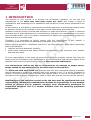
1 INTRODUCTION
The purpose of this manual is to provide the knowledge necessary for the use and
maintenance of the Mitre saw with table stand Art. 0275 and create a sense of
responsibility and knowledge of the capabilities and limitations of the device entrusted to the
operator.
As the machine is entrusted to experienced and skilled operators, the following machine must
be perfectly known by the operator if you want it to be used safely and effectively.
Operators must be properly trained and prepared, so make sure that this manual is read and
consulted by the staff responsible for commissioning, operation and maintenance of the Mitre
saw with table stand. This is to make all operations the safest and most effective possible for
those who carry out these tasks.
Therefore, it is imperative to strictly comply with the requirements in this manual, a
necessary condition for safe and satisfactory operation of the machine.
Before starting operation, installation and use of the Mitre saw with table stand, authorized
staff must therefore:
read this technical document carefully;
know which protections and safety devices are available on the machines, their location
and how they work.
m
o
c
.i
It is the responsibility of the buyer to ensure that users are properly trained, that they are
aware of all the information and instructions in this document and that they are aware of the
potential risks that exist while working with the Mitre saw with table stand.
v
r
The manufacturer waives any and all responsibility for damage to people and/or
things caused by non-observance of the instructions in this manual.
The Mitre saw with table stand was designed and built with mechanical guards and safety
devices designed to protect the operator/user from possible injury. It is strictly forbidden to
modify or remove guards, safety devices and caution labels. If you do so temporarily (for
example, for the purposes of cleaning or repair), make sure that no one can use the machine.
e
f
Modifications to the machines carried out by the user must be considered their sole
responsibility, therefore the manufacturer declines all responsibility for any damage
caused to persons and/or property resulting from maintenance performed by
unqualified personnel and in a manner different from the operating procedures
shown below.
Page 5 of 44
MACHINES AND
ACCESSORIES
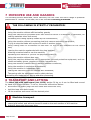
Graphic representation of safety, operational and risk warnings
The following boxes are designed to attract the attention of the reader / user for the proper
and safe use of the machine:
Attention
This highlights behavioural rules to prevent damage to the machine and/or the occurrence of
dangerous situations.
m
o
Residual Risks
This highlights the presence of dangers that cause residual risks to which the operator must
pay attention in order to avoid injury or damage to property.
1.1 Preface
c
.i
For safe and easy operation of the Mitre saw with table stand, this manual must be read
carefully in order to acquire the necessary knowledge. In other words, durability and
performance are strictly dependent on how it is used.
Follow the instructions contained herein, in addition to the general precautions to be observed
while working. Even if the operator is already familiar with the use of lifting equipment, it is
necessary to:
Acquire full knowledge of the lifting platform.
Read this manual carefully to understand: operation, safety devices and all necessary
precautions. All this is to allow safe use of the machine.
Wear appropriate clothing for the job.
The operator must wear appropriate clothing to prevent the occurrence of unforeseen
accidents.
Take proper care of the lifting platform.
v
r
e
f
Machine operation
The machine must only be used by qualified personnel trained to use the machine by
authorized personnel.
Page 6 of 44
MACHINES
AND
ACCESSORIES
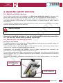
2 SAFETY WARNINGS
2.1 General safety regulations
Accident
There is always a risk of injury during cutting operations due to accidental contact of
body parts with the moving tool, flying debris from the workpiece, tool breakage or
ejection of a badly blocked workpiece.
There is no "intrinsic" means of safety, just as there is no worker who, while careful,
can "always" avoid an accident. Therefore, DO NOT underestimate the risks associated
with using the machine and concentrate on the work in progress.
Risks related to Using the Machine
m
o
c
.i
Despite the implementation of all safety devices for safe use of the machine, it is necessary
take note of all the requirements for the prevention of the accidents reported in various parts
of this manual.
v
r
Risks related to Using the Machine
Every person who is responsible for the use and maintenance of the machine should have first
read the instruction manual, particularly the chapter on safety information.
It is recommended that the plant safety manager get written confirmation of the above.
e
f
Risks associated with using the Machine
During all work phases with the machine, you should proceed with great caution in order
to avoid damage to persons, to the property or to the machine itself.
Please use the machine only for its expected uses.
Don't tamper with the safety devices equipping the machine.
Operator Protection
Before starting any work on the machine, the operator must wear the appropriate personal
protective equipment (PPE) such as gloves and eye protection (see section 6.3 of this
manual).
Page 7 of 44
MACHINES AND
ACCESSORIES
1. Always check the efficiency and integrity of the machine.
2. Before connecting the machine to the mains, make sure that the blade is not damaged
or badly worn. Make sure that the switch is in the neutral position.
3. Do not start the machine in an enclosed or poorly ventilated area, or in the presence of
a flammable and/or explosive atmosphere. Do not use the machine in damp and/or wet
locations, or those exposed to rain or humidity.
It is prohibited to install and use the machine outdoors.
4. User advance, check that the bearing surface of the machinery results flat, of suitable
strength and of sufficient ergonomics: for this purpose made with the aid of a
workbench.
5. Secure the workpiece. Use the vice on the machine to keep the workpiece stable.
6. Avoid starting accidentally.
7. Before starting the machine, get used to ensuring that no remaining maintenance and
service keys are inserted.
8. Connect dust extraction equipment. Make sure a vacuum is connected to the machine,
for the suction of dust and chips produced.
9. Keep the workplace tidy and free from obstruction; disorder causes accidents.
10.Make sure that your work environment is forbidden to children, strangers and animals.
11.Do not perform tasks on the machine other than those for which it was designed. Only
use the machine in the manner in which it was intended, as described in this instruction
manual.
In particular, do not use the mitre saw to cut material other than wood!
12.Before starting work, inspect the piece and remove any foreign material.
13.Remain balanced whilst working.
14.Work areas must be well lit.
15.Always wear eye protection and protective gloves while working. If dust is produced,
use the appropriate masks.
16.Wear appropriate clothing. Loose clothing, dangling jewellery, long hair, etc., can get
caught in the moving parts or the disc, causing irreparable injury.
17.Do not leave the machine until the disc has completely stopped. For this purpose, only
use the stop controls to stop the machine.
18.Do not slow down or stop the disc with your hands or other objects.
Allow the disc to stop on its own!
19.Take proper care of the cutting tools. Cutting tools must be kept intact and clean to
ensure the best possible performance.
20.Never use blades that are less than 2.7 mm thick.
21.Never use the blades for materials other than wood.
22.Replace worn and/or damaged parts, check that the repairs and protections work
properly before operating. If necessary, have the machine checked by the service
support personnel. Use only original spare parts.
23.Unplug the power cord of the machine from the power outlet when:
the machine is not being operated;
it is left unattended;
performing maintenance or registration, because the machine does not work
properly;
the power cable is damaged;
v
r
c
.i
e
f
Page 8 of 44
m
o
MACHINES
AND
ACCESSORIES
replacing the disc;
it is being moved or transported;
during cleaning operations.
24.Do not use the machine in areas with a risk of fire and/or explosion.
25.It is recommended that users of this publication, for maintenance and repair, have a
basic knowledge of the mechanical principles and procedures inherent in repair
technique.
26. The company safety officer is required to make sure that machine operators
have read and understood this manual in its entirety.
27. The company safety manager is responsible for monitoring the company's risk
status according to Legislative Decree no. 81/08 and subsequent modifications
and amendments.
m
o
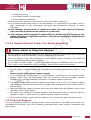
2.2 2.1 General Electric Power Tool Safety Standards
c
.i
Risks related to Using the Machine
1. Do not modify the electrical system in any way. Any attempt in this regard may jeopardize
the operation of electrical devices, causing malfunction or accident.
2. Work carried out in the electrical system of the machine must, therefore, be carried out
only by qualified and authorized personnel.
3. If one hears unusual noises, or feels something strange, immediately stop the machine.
Then carry out an inspection and, if necessary, perform any repairs as required.
v
r
1. Ensure supply voltage complies with the label and technical specifications (230 V / 50
Hz).
Never use any other type of power supply!
2. It is necessary to use a device for the automatic interruption of the electric power
supply, which is to be coordinated with the machine's electrical system. (double
isolation
). For more detailed information, contact a trusted electrician.
e
f
3. The mains power outlet should be bipolar grounded 10/16 A, 250 V), extension cables
must have sections that are the same or greater than the sections of the power cable of
the machine.
4. Make sure that the power cord does not come into contact with hot objects, wet or oiled
surfaces, and/or sharp edges.
5. The power cord should be checked regularly and before each use to check for signs of
damage or wear. If these are not in good condition, replace the cable.
6. Do not use the power cord to lift the machine or to remove the plug from the socket.
2.3 Technical Support
For any problems or concerns, please contact, without hesitation, the dealer from whom you
purchased the machine, who has competent and specialized staff, specific equipment and
spare parts.
Page 9 of 44
MACHINES AND
ACCESSORIES
2.4 Other provisions
It is forbidden to tamper with safety devices
The first thing to do when starting work is to check the presence and integrity of the
protections and the operation of the safety devices.
If any defect is encountered do not use the Mitre saw with table!!
m
o
Even more so, it is strictly forbidden to modify or remove guards, safety devices,
labels and indication signs.
v
r
c
.i
e
f
Page 10 of 44
MACHINES
AND
ACCESSORIES
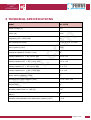
3 TECHNICAL SPECIFICATIONS
Model
Art. 0275
Rated voltage (V)
230
m
o
Power (W)
1800
Frequency (80 - 16000 Hz)
50
Disc dimensions (mm)
315 x 30 x 3.0 Z40
c
.i
Motor speed (r/min)
Peripheral speed of the disc (m/s)
Cutting capacity 0° ÷ 90° (mm) HxL
v
r
Cutting capacity 45° ÷ 90° (mm) HxL
Cutting capacity 0° ÷ 45° (mm) HxL
e
f
Cutting capacity 45° ÷ 45° (mm) HxL
Upper cutting capacity (mm)
4000
56
100 x 170
100 x 118
67 x 170
62 x 118
57
Dimensions in open position (mm)
575 x 700 x 730
Weight (kg)
26
Acoustic power level LwA (dB (A))
105
Acoustic pressure level at operator's workstation L pA
94
(dB(A))
Vibration transmitted to the hand-arm system (m/s2)
< 2.5
Page 11 of 44
MACHINES AND
ACCESSORIES
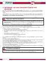
4 INTENDED USE AND DESCRIPTION OF THE
MACHINE
The Mitre saw with table stand (Art. 0275) is only used for dry cutting of wooden planks
and/or boards, within the limits recommended by the Manufacturer and the safety and health
norms.
Other types of use, or the extension of use beyond that envisaged, does not correspond to
the designation attributed by the manufacturer, and therefore the latter cannot accept any
responsibility for any damage resulting therefrom.
m
o
Improper machine operation
The machine was designed and manufactured for a specific use, different uses and noncompliance with technical parameters established by the Manufacturer may be hazardous
to the operator.
In particular, it is absolutely forbidden to cut non-wood materials.
c
.i
The Mitre saw with table stand (Art. 0275) can perform vertical cuts with disc inclination ±
45°, also the support table can be rotated right or left up by to 45°.
Refer to chapter 10 of this manual to view the operating modes of the machine in detail.
It mainly consists of the following parts:
the fixed base, with clamp for locking the workpiece;
the electric motor and the circular blade (disc) mounted on the cutting unit of the
machine;
the handle for manual operation;
the support table for using the circular bench saw.
v
r
e
f
For a detailed view of the various parts of the machine, refer to paragraph 4.1 and 4.2 of this
manual.
The motor rotates at a constant speed.
The mitre saw must be installed and used on flat supporting surfaces, with adequate
ergonomic and resistance features, such as a workbench or a base.
The mitre saw can only operate in indoor workplaces (production halls, warehouses,
woodworking areas, etc.) and in any case away from moisture and the weather.
The operating temperature range is – 5 / +50°C.
The environment must also be sufficiently illuminated so as to ensure operation in maximum
safety (at least 200 lux is recommended).
Prohibited workplaces
Do NOT use the machine in areas with are humid, wet and exposed to rain, snow or hail.
Do NOT use the machine in areas with a high risk of fire and/or explosion !
Page 12 of 44
MACHINES
AND
ACCESSORIES
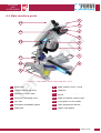
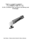
4.1 Main machine parts
1
14
2
3
13
m
o
4
12
5
c
.i
11
10
v
r
9
e
f
6
7
8
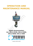
Figure 1 – Main parts of the mitre saw Art. 0275.
1
Work table
2
Closure unhooking lever
3
Buttons for bench saw
4
8
Head rotation lever / knob
9
Supports
10
Workpiece
device
clamping
adjustment
Mitre saw operating lever
11
Head inclination locking lever
5
Disc saw
12
Fixed guard on the blade
6
Automatic adjustable guard
13
Table adjustment device
7
Stabilizers
14
Upper fixed guard
Page 13 of 44
MACHINES AND
ACCESSORIES
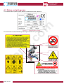
4.2 Plates and pictograms
The identification plate shown below is attached to the machine.
m
o
Figure 2 – Identification Plate.
The machine has the following warning and attention pictograms:
v
r
c
.i
e
f
Page 14 of 44
MACHINES
AND
ACCESSORIES
PLATE IN ITALIAN
PLATE IN ENGLISH
NON
DO NOT
REMOVE
RIMUOVERE
m
o
SAFETY DEVICES
I DISPOSITIVI DI
SICUREZZA
ATTENTION
ATTENZIONE
È VIETATO ESEGUIRE LAVORI SU
APPARECCHIATURE ELETTRICHE SOTTO
TENSIONE
EVENTUALI DEROGHE DEVONO ESSERE
AUTORIZZATE DAL CAPO RESPONSABILE
IN CONDIZIONI DI PARTICOLARE PERICOLO DEVE
ESSERE PRESENTE UN’ALTRA PERSONA OLTRE A CHI
ESEGUE IL LAVORO
INIZIARE I LAVORI SOLO AD AVVENUTA
ATTAZIONE DELLE MISURE DI SICUREZZA
IT IS PROHIBITED TO WORK ON LIVE ELECTRICAL
EQUIPMENT
ANY EXCEPTIONS MUST BE APPROVED BY THE HEAD
MANAGER
UNDER PARTICULARLY DANGEROUS CONDITIONS,
ANOTHER PERSON MUST BE PRESENT WHO IS NOT
PERFORMING THE WORK
ONLY BEGIN WORKING WHEN SAFETY MEASURES
HAVE BEEN IMPLEMENTED
c
.i
In accordance with Legislative Decree 81/08 on accident
prevention
In ottemperanza al Dgs.81/08 relativo alla prevenzioni
infortuni
ATTENZIONE!!
LEGGERE LE
MACCHINA
ATTENTION!!
ISTRUZIONI PRIMA DI
UTILIZZARE
LA
v
r
NON AVVICINARE LE MANI ALL’UTENSILE IN MOVIMENTO
NON AFFERRARE
ARRESTARLO
L’UTENSILE
CON
LE
MANI
PER
NON REGOLARE LA MACCHINA MENTRE è IN FUNZIONE
INDOSSARE
SEMPRE
IDONEE
PROTEZIONI
QUALI
OCCHIALI E MASCHERINE QUALORA VENGA PRODOTTA
POLVERE
SCOLLEGARE
LA
MACCHINA
DALL’ALIMENTAZIONE
ELETTRICA IN CASO DI RIPARAZIONI O REGOLAZIONI
NON INDOOSSARE INDUMENTI SVOLAZZANTI, GIOIELLI,
MACCHINA, E CAUSARE DANNI IRREPARABILI
SCOLLEGARE
LA
MACCHINA
DALL’ALIMENTAZIONE
ELETTRICA PRIMA DI ESEGUIRE MANUTENZUIONE,
REGOLAZIONI E RIPARAZIONI
e
f
READ THE INSTRUCTIONS BEFORE USING THE MACHINE
KEEP HANDS AWAY FROM THE TOOLS IN MOVEMENT
DO NOT GRAB THE TOOL WITH YOUR HANDS TO STOP IT
DO NOT ADJUST
OPERATION
ALWAYS WEAR SUITABLE PROTECTIVE EQUIPMENT SUCH
AS GOGGLES AND MASKS IF POWDER IS PRODUCED
DISCONNECT THE MACHINE FROM THE POWER SUPPLY IN
THE EVENT OF REPAIRS OR ADJUSTMENTS BEING MADE
DO NOT WEAR LOOSE CLOTHING, JEWELLERY, MACHINE,
AS IT CAN CAUSE IRREVERSIBLE DAMAGE
DISCONNECT THE MACHINE FROM THE POWER SUPPLY
BEFORE PERFORMING MAINTENANCE, REPAIRS AND
ADJUSTMENTS
THE
MACHINE
WHILE
IT
IS
IN
Page 15 of 44
MACHINES AND
ACCESSORIES
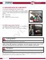
5 DESCRIPTION OF CONTROLS
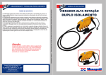
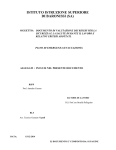
5.1 Control Buttons for bench saw
At the front of the machine, when it is closed in "Bench
Saw" mode, the active commands are two electromagnetic
buttons - Start (GREEN) and Stop (RED) located near the
handle.
15
Start button
16
Stop button
17
Button for unhooking the head
17
m
o
15
16
Figure 3 – Buttons for start/stop
and unlocking the head
c
.i
5.2 Mitre saw control button
The switch for starting the mitre saw, or activating the
disc is positioned on the control handle.
18
sustained action switch located inside the handle
e
f
v
r
Cutting hazard
18
7
Figure 4 - Start button.
It is absolutely forbidden to by-pass the safety feature constituted by the sustained action
command by locking the button in the "ON" position.
NOTE: Given the operator's workstation and the reduced overall size of the
machine, the sustained action start button is also an emergency stop switch.
Emergency
In emergency situations, immediately release the start button (18) and the handle and move
away from the machine.
Even during normal operation, to stop the rotation of the blade, release the start button (18),
it automatically returns to the raised position ("OFF").
Page 16 of 44
MACHINES
AND
ACCESSORIES
Cutting hazard
After releasing the start button (18), the blade continues to rotate by inertia.
Do not put body parts like hands and/or fingers near the moving blade!
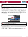
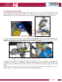
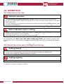
5.3 Locking the head
m
o
The machine is supplied closed, i.e. with the head attached and in "bench saw" mode. To be
able to raise the head and use the machine in mitre saw mode it is necessary to push the
bracket (19) inwards and at the same time the hook (20) backwards. After unlocking and
raising the head it is necessary to remove the black protection device on which the blade is
resting, extracting it backwards.
Note: When the hook is fully open and the head is free it pops up due to the spring on its
underside. Do NOT operate with your hands or head in the trajectory of the released head,
but stand to the side!
c
.i
19
e
f
v
r
20
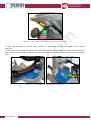
Figure 5 - Opening the head locking hook.
Removal of parts and components
All parts removed from the machine should ALWAYS be stored in a safe place to prevent them
from breaking and/or getting lost.
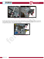
When the head is completely open it locks in the open position. In this position the adjustable
blade guard closes preventing access.
In order to use the machine in mitre saw mode it is necessary to release the head and grasp
the handle (see chap. 10 - Operation). To release the head there is a button (17 in Figure 3)
near the handle.
Page 17 of 44
MACHINES AND
ACCESSORIES
m
o
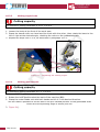
Figure 6 – Releasing the head from the open position
c
.i
To use the machine in "bench saw" mode it is necessary to lock the head in the closed
position.
To do this it is necessary to install the fixed protection device under the blade which also has
the function of pushing the safety pin and allowing the closure of the hook (20) of the head
itself.
v
r
e
f
Figure 7 – Lower protection device in position.
Page 18 of 44
MACHINES
AND
ACCESSORIES
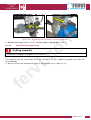
5.4 Adjustment knobs
At the front part of the machine there is a knob (8 in Figure 1) for locking the head in an
angled position relative to the base. The angle can be discovered by referring to the
graduated scale (21) positioned below the base and which is revealed by the rotation itself.
m
o
21
c
.i
8
Figure 8 – Rotation of the head.
For the inclination of the head it is necessary to rotate the lever (22) located behind the
machine anticlockwise and then grasp the work table with both hands and tilt the head by
reading the angle on the graduated scale located under the support.
v
r
e
f
22
Figure 9 – Inclination of the head.
In "bench saw" mode it is possible to adjust the depth of the cut by raising or lowering the
worktable. To do this it is necessary to loosen the screws (23) located to the right of the
handle, under the table, and the ring nut (24) on the left side of the blade, again under the
table.
Then rotate the knob (25) clockwise to lift the table and reduce the depth of the cut,
anticlockwise to lower the table and increase the cutting capacity.
Page 19 of 44
MACHINES AND
ACCESSORIES
23
24
23
25
m
o
Figure 10 – Adjusting the table height.
On the right and the left part of the support guide square (mitre saw mode) there is a slot for
the workpiece clamp. This clamp has a screw (26) for locking onto the guide and a screw (27)
to tighten the pieces in position during cutting.
c
.i
27
v
r
26
e
f
Page 20 of 44
Figure 11 – Workpiece clamp.
MACHINES
AND
ACCESSORIES
6 MACHINE SAFETY DEVICES
6.1 Electrical safety devices
In the event of malfunction or breakdown, the Mitre saw with table stand is equipped with
power cable and plug without grounding conductor, as it is equipped with double isolation.
The plug must be plugged into an appropriate outlet, the metal frame of the machine nongrounded. Extension cables must be of a section equal to or greater than the power cable of
the machine.
The line must be equipped with an automatic electric power disconnection system coordinated
with the electrical system of the machine.
m
o
Electric shock
c
.i
Improper connection of the machine’s grounding conductor can result in the risk of electric
shock.
Check with a qualified electrician if you don't understand the grounding instructions
or if you have any doubts about grounding the machine.
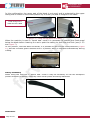
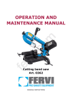
6.2 Mechanical risk safety devices
v
r
PROTECTIVE DISC CASING
The safety guards on the cutting disc are constituted by fixed casing and movable casing, as
shown in Figure 12 in "mitre saw" mode.
They have the task of preventing parts of the operator's body, particularly hands and/or
fingers, from coming into direct contact with the disc.
Furthermore, this prevents the splinters, dust or blade fragments that eventually get
separated from being thrown towards the operator's face.
The movable casing on the disc is articulated to the saw body, after being unlocked by using
the locking lever (ref. 1), it opens progressively as the blade is lowered to allow the cutting of
the workpiece.
Conversely, the blade is completely protected when it is in the resting position, i.e. when fully
raised.
e
f
Fixed casing on the
sides and behind the
blade
Movable casing under
the disc (cutting area)
Figure 12 – Disc protective casing.
Page 21 of 44
MACHINES AND
ACCESSORIES
In this configuration, the upper part of the blade is not used, and is protected by the upper
casing that is locked in the closed position by a screw (28) and is integral to the table.
Fixed casing on the
blade above the table
m
o
28
Figure 13 – Fixed casing above the table.
When the machine is used in "bench saw" mode it is necessary to position the fixed guard
below the blade before lowering it so as to push the safety pin and close the hook (see p. 5.3
and Figure 7).
In this position, with the table horizontal, it is possible to remove the fixed protection (Figure
13) but the movable guard remains and in a position which is adjusted automatically during
cutting.
v
r
c
.i
Figure 14 – Upper movable guard.
e
f
Safety accessory
When using the machine in "bench saw" mode it may be necessary to use the workpiece
pusher accessory supplied, especially when small pieces are being machined.
Figure 15 – Workpiece pusher accessory.
Stabilizers
Page 22 of 44
MACHINES
AND
ACCESSORIES
The machine is equipped with two lateral stabilizers (ref. 7 in Figure 1) to be inserted into the
specially drilled holes on the base of the machine.
m
o
Figure 16 – Workpiece pusher accessory.
6.3 Personal Protective Equipment (PPE)
Use of PPE
c
.i
ALWAYS use appropriate personal protective equipment (PPE), such as:
Gloves,
Goggles or face shields;
Overalls or aprons;
Safety shoes;
Ear protection devices (ear muffs, ear plugs, etc.).
PROTECTIVE GLOVES -
e
f
v
r
PROTECT YOUR EYES - PROTECTIVE SCREEN -
PROTECTIVE CLOTHINGI - PROTECTIVE SHOES - PROTECT YOUR HEARING
Figure 17 - Personal Protective Equipment.
Page 23 of 44
MACHINES AND
ACCESSORIES
7 IMPROPER USE AND HAZARDS
The following actions described, which obviously can not cover the entire range of potential
possibilities of "misuse" of the saw, are to be considered strictly prohibited.
THE FOLLOWING IS STRICTLY PROHIBITED!
Holding the piece to be cut with your hand;
Using the machine without efficient safety guards;
Using the machine for purposes other than those for which it is designed, in particular, for
cutting materials other than wood;
Exceeding the cutting capacity stated by the manufacturer;
Using the machine without connecting dust/chip vacuum extraction equipment;
Trying to stop the blade with a piece of wood or another object;
Using cutting discs of a thickness of less than 3.2 mm or with adapters for the central
hole;
Leaving the machine unattended with the plug inserted;
Allowing untrained staff to use the machine;
Operating this machine if you are not psychophysically fit;
Using the machine without due care;
Using the machine without the use of appropriate personal protective equipment, such as:
shoes and safety gloves, goggles or shields, earmuffs etc.;
Using the machine outdoors and in adverse weather conditions;
Using the machine in explosive atmospheres;
Using the machine in inadequate light;
Letting the machine come into contact with foodstuffs;
Tampering with the equipment and/or safety devices;
Lubricating the blade before, during and after processing.
c
.i
v
r
e
f
m
o
8 TRANSPORT AND LIFTING
The Mitre saw with table stand (Art. 0275) weighs 26 kg, so it can be lifted and moved
by hand by a single operator. To do so, follow the instructions below:
disconnect the power plug from the outlet and collect the cord;
hold the base with both hands;
lift the machine and move it to the desired point.
Machine transport
All transport operations are ALWAYS performed with the machine stopped with the head
closed and locked, and without pieces of wood on the work surface of the machine.
ALWAYS disconnect the power plug.
Page 24 of 44
MACHINES
AND
ACCESSORIES
9 ASSEMBLY AND COMMISSIONING
9.1 Unpacking instructions
The Mitre saw with table stand (ART. 0275) is supplied ready for use, with a steel disc
315 x 30 x 3.0 mm and packed in a cardboard box.
Inside the package, in addition to the machine, there is a hex key, the workpiece pusher
accessory, this manual, the EC declaration of conformity.
Before disposing of packing, check no parts of the machine, including the user manual or
other documentation, are thrown away.
Also, make sure that at the time of unpacking, the machine is in perfect condition.
The manufacturer is not liable for any defects or missing parts five days after
delivery.
Standard packaging
m
o
c
.i
The packing materials (plastic bags, polystyrene, cardboard, etc.) must not be left within
reach of children as a source of potential danger.
Respect the environment! Dispose of the packaging in accordance with current legislation.
e
f
v
r
9.2 Positioning and fixing on the bench
Loss of Stability
FIX THE MITRE SAW WITH TABLE STAND ON A SURFACE THAT IS SOLID AND STRONG,
USING SUITABLE BOLTS, TO PREVENT IT FROM FALLING OVER AND SO IT DOES NOT CAUSE
VIBRATIONS.
Cleaning the work bench
Before fixing the machine in place, clean the workbench of any materials and dirt that may be
present.
Page 25 of 44
MACHINES AND
ACCESSORIES
Fix the machine on a work bench (or another support surface) which is flat, solid and strong,
using special bolts, so as to prevent accidental movement or overturning during operation,
and excessive vibration transmitted to the operator.
m
o
Figure 18 – Fastening holes on the machine.
The machine is equipped with rubber support pads capable of reducing noise and vibration.
c
.i
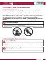
9.3 Anti-overturn stabilizers
At the sides of the machine there are anti-overturn stabilizers, these are attached to the
machine by means of screws placed at the rear of the machine.
v
r
e
f
Figure 19 – Extension of the stabilizers.
9.4 Connecting the suction system
The machine can be connected to a dust suction device.
The suction device must be pull a current of air with a
minimum speed of 20 m/s for dry dust and 28 m/s for
damp dust.
Figure 20 - Discharge duct.
It is important to respect the environment: to dispose of the shavings in compliance
with current legislation.
Page 26 of 44
MACHINES
AND
ACCESSORIES
9.5 Connecting the power plug
1. Insert the power supply plug into a double pole socket without grounding (10/16 A, 250
V).
2. Start the machine by pressing the start button and make sure that the direction of
rotation of the blade is as indicated by the arrow on the protective casing.
3. Before starting the cutting operation, check the saw as follows:
let it spin freely for at least 1 minute;
with the protections in place;
without the presence of staff.
During the test run, no operator and no other person should be within range of
the machine.
c
.i
v
r
e
f
m
o
Page 27 of 44
MACHINES AND
ACCESSORIES
10 OPERATION
10.1Instructions for Use
Machine operation
The mitre saw with table stand (Art. 0275) should only be used for cutting wood.
Do not cut metal parts, make sure there are no nails or other metal parts in the wood
being machined.
Do not cut beams of dimensions exceeding the maximum permissible cutting capacity (see
Technical Specifications).
m
o
Risk of abrasion and/or cutting
c
.i
Before using the machine, make sure that it is rigidly fixed to the workbench to prevent
unwanted movement or loss of stability.
Wear appropriate personal protective equipment (PPE).
As anticipated, the Mitre saw with table stand (Art. 0275) can perform vertical cuts,
inclined at ± 45° to the vertical and angled between -45° and +45° by rotating the support
base.
v
r
10.2Use of the mitre saw - Cutting from the top
Cutting hazard
e
f
Make sure the machine is in the correct configuration before starting operation.
Check that all guards are in place and that the safety systems are operational
Always use the grip to hold the workpiece in place.
Cutting capacity
The maximum cutting thickness is 100 x 170 mm.
To operate correctly, proceed as follows:
Page 28 of 44
MACHINES
AND
ACCESSORIES
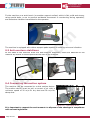
10.2.1
Making straight cuts
1. Unlock the cutting disc so that it is possible to lift the
mitre saw, moving the hook backwards.
m
o
Figure 21 – Open hook.
Pay attention to the upward displacement of the
work table when the hook leaves its housing.
2. Position the piece to be cut by placing it against the
squares, adjust the supports for locking the
workpiece, then tighten the clamp screws.
c
.i
Figure 22 – Closing the clamps.
3. Grasp the handle, push the lock button (ref. 17 in Figure 3) and press the start
switch and wait until the disc has reached its nominal speed of rotation.
4. Lower the disc towards the workpiece, in this way, the lower casing opens
automatically with the pushing of the hand.
5. Cut as required without slowing down the motor. At the end of the cut, lift the
disc, the protection device will cover it automatically.
6. At the end of the work, release the start button and wait for the blade to stop.
v
r
e
f
Cutting hazard
After releasing the switch, the disc will continue to rotate by inertia.
Do not put body parts like hands and/or fingers near the moving blade!
Page 29 of 44
MACHINES AND
ACCESSORIES
10.2.2
Making angled cuts
Cutting capacity
The maximum cutting thickness is 100 x 170 mm.
1. Loosen the knob at the front of the work area.
2. Grasp the handle with one hand and the knob with the other, then rotate the base to the
left or right at the desired angle, checking the value on the graduated scale.
3. Repeat the steps from 1 to 6, as described in paragraph 10.2.1.
21
c
.i
m
o
v
r
8
Figure 23 - Adjusting the cutting angle.
10.2.3
e
f
Making inclined cuts
Cutting capacity
The maximum cutting thickness is 67 x 170 mm.
1. Rotate the lever positioned at the back of the machine (22).
2. Grasp the motor-blade unit with both hands and tilt it in the desired direction.
This will make it possible to tilt the saw to the pre-marked position on the graduated scale
where the corresponding angle is shown (see the
3. Figure 24).
Page 30 of 44
MACHINES
AND
ACCESSORIES
m
o
22
Figure 24 – Adjusting the inclination to fixed positions.
4. Repeat the steps from 1 to 6, as described in paragraph 10.2.1.
10.2.4
c
.i
Inclined and angled cuts
Cutting capacity
The maximum cutting thickness is 62 x 118 mm.
v
r
The machine can be used with the dual inclination of the rotated turntable and with the
inclined blade.
To do this, follow the instructions given in paragraphs 10.2.2 and 10.2.3.
e
f
Page 31 of 44
MACHINES AND
ACCESSORIES
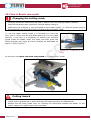
10.3Use in Bench saw mode
Changing the cutting mode
Carefully follow the instructions on how to switch from one cutting mode to another.
Make sure that the saw is perfectly vertical before closing it.
Make sure the machine is not connected to the power supply, i.e. that the power plug is
disconnected from the mains before changing the operation mode.
To use the upper cutting mode it is necessary to close the
saw, that is, move it all the way down and lock it in the closed
position. To do this, it is necessary to position the movable
guard under the blade, lower the head, and then press the
safety bracket and move the hook forward, as described on
page 17 and in Figure 7.
c
.i
m
o
Figure 25 - Close-up of the
hook
At this point the Mitre saw with table stand is in “Bench saw” mode.
v
r
e
f
Figure 26 – Closed Machine.
Cutting hazard
Make sure the machine is in the correct configuration before starting operation.
Check that all guards are in place and that the safety systems are operational
Always use the piece guide lever for pushing the workpiece towards the blade. In any
event, keep your fingers away from the blade.
Page 32 of 44
MACHINES
AND
ACCESSORIES
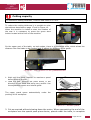
Cutting capacity
The maximum cutting thickness, in bench saw mode is 57 mm.
To reduce the cutting thickness it is possible to raise
the table as described on page 17 and in Figure 10.
When the machine is closed to start the rotation of
the saw it is necessary to press the green start
button located at the front of the machine.
m
o
Figure 27 - Saw start-up.
On the upper part of the table, on both edges, there is a graduated scale, which allows the
distance from the blade to be checked and to adjust the distance of the guide.
c
.i
v
r
e
f
Figure 28 – The 0 position on the graduated scale.
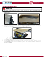
1. Wait until the blade reaches its maximum speed
before starting the cut.
2. Feed the saw, pushing the piece slowly in the
direction of the blade and being very careful. Use
the adjustable square as a lateral guide.
Figure 29 - Use of saw.
The upper guard opens automatically under the
pushing of the workpiece.
Figure 30 – Movable guard.
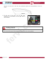
3. Cut as required without slowing down the motor. When approaching the end of the
workpiece use the special push-piece device, placed under the table, to complete
Page 33 of 44
MACHINES AND
ACCESSORIES
the cut. At the end of the cut, the protective guard will automatically cover the
blade.
m
o
4. At the end of the work, turn off the saw,
pressing the red button on the right side of
the machine.
c
.i
Figure 31 - Stopping the saw.
Cutting hazard
v
r
After releasing the switch, the disc will continue to rotate by inertia.
Do not put body parts like hands and/or fingers near the moving blade!
e
f
Page 34 of 44
MACHINES
AND
ACCESSORIES
11 MAINTENANCE
Any maintenance, except for that specifically listed in this manual should be performed by
qualified staff authorized by the manufacturer.
This manual does not elaborate information on disassembly and maintenance, as these
operations should always be carried out exclusively by Technical Assistance staff.
m
o
Electric shock
Before maintenance or checks, turn off the machine and ALWAYS unplug the plug from the
power outlet. This is so that there is no risk of electric shock.
11.1Accessories
c
.i
For routine maintenance, adjustment operations and safe use several accessories are
supplied such as:
1 a hex key for the blade fastening screw,
2 a workpiece pusher bar,
3 stabilizing brackets.
v
r
11.2Ordinary maintenance
ROUTINE AT THE END OF EACH PROCESSING
Regularly clean and take care of the machine to guarantee proper efficiency and a long
working life.
Use a compressor to blow off chips, sawdust and dust that has accumulated on the floor of
the machine and on the workbench at the end of each machining operation.
e
f
Working with the Air Compressor
ALWAYS wear the protective goggles when using compressed air.
Check the state of the Saw and the plates at the same time; if these are no longer legible
request replacements.
Use only a dry cloth to clean the outside of the machine.
Cleaning the Machine
DO NOT use detergents or any solvents; the plastic parts are easily damaged by chemical
agents.
Page 35 of 44
MACHINES AND
ACCESSORIES
11.3Replacing the blade
Wear PPE
ALWAYS wear suitable protective gloves (to reduce the risk of cut) when replacing the blade.
1. Remove the upper blade guards: both the fixed and the moveable guards, sliding it off the
dividing cutter.
m
o
c
.i
Figure 32 – Fixed and moveable guards.
2. Loosen the screws (23) and the ring nut (24) that hold the table in place and remove
them from the machine.
v
r
e
f
Figure 33 – Removing the table.
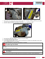
3. Unhook the blade opening the lock (20) and move it into a vertical position.
4. Lock the shaft movement of the blade using the lever to the right of the machine: pull the
lever and at the same time turn the blade by hand until the lever has been inserted into
the hole in the shaft.
Page 36 of 44
MACHINES
AND
ACCESSORIES
m
o
Figure 34 – Locked blade movement.
5. Hold down the locking lever and unscrew the bolt clockwise using the hex key provided.
The left-nut is loosened by turning it clockwise.
6. Hold the washer and then the flange and remove them from the shaft.
v
r
c
.i
e
f
Figure 35 – Removing the external flange.
7. Hold the disc with both hands to remove it from the shaft.
8. Clean the inner and outer flanges.
9. Insert the new disc, taking care to verify the direction of rotation as indicated by the arrow
on the fixed casing and on the blade.
10.To close the machine, follow the instructions in reverse.
Replacing the blade
When replacing the disc, fit one with the same dimensions. Do not use reducers/adapters on
the shaft
Do not disassemble the inner flange.
Accident
NEVER use the Mitre saw with table stand with the guards removed or partly assembled.
Page 37 of 44
MACHINES AND
ACCESSORIES
12 WAREHOUSE STORAGE
In the event that the machine should be stored and unused for some time, it must be kept in
a closed environment free of moisture to avoid damage and/or deterioration.
13 DISPOSAL OF PARTS AND MATERIALS
If the machine is to be scrapped, its parts must be disposed of differently.
Respect the Environment!
m
o
Contact a specialist centre for the collection of metallic materials.
The structure of the Mitre saw with table stand is made from steel, while some parts such
as the handle, the casing of the electric motor, etc. are made from polymeric material.
In this regard, divide the materials according to their nature, employing specialist companies
which are authorised for their disposal, in accordance with the requirements of law.
c
.i
v
r
Respect the Environment!
Dispose of tailings (shavings, sawdust, etc.) in compliance with current legislation.
14 FAULT FINDING
PROBLEM
e
f
Noisy operation
PROBABLE CAUSE
A) Damaged bearings.
B) Bearings not lubricated.
C) Disc friction
A)
B)
The motor will not C)
start.
D)
Electrical power supply.
Wiring connections
Burnt motor windings.
Broken switch.
SOLUTION
A) Contact Customer Service.
B) Lubricate.
C) Remove / replace the disc and
check sliding.
A) Check the mains power supply.
B) Check the wiring connections.
C) Contact Customer Service.
D) Contact the service department.
Poor
cutting A) Excessive pressure on A) Apply less pressure.
the workpiece.
B) Check the degree of wear of the
efficiency
or
B) Worn disc or unsuitable
disc
excessive
material.
overheating of the
C) Use a disc of different material.
disc.
C) Material too hard.
Page 38 of 44
MACHINES
AND
ACCESSORIES
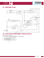
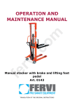
15 WIRING PLAN
m
o
v
r
c
.i
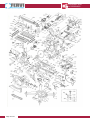
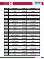
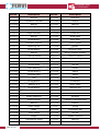
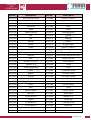
16 EXPLODED VIEW AND SPARE PARTS
e
f
Always clearly indicate:
the symbol and the serial number of the machine;
the code number of the parts;
number of parts;
exact address of your company.
Page 39 of 44
MACHINES AND
ACCESSORIES
v
r
c
.i
e
f
Page 40 of 44
m
o
MACHINES
AND
ACCESSORIES
Part No.
Description
Part No.
Description
0275/001
M8x30 Hex head screw
0275/034
Gear
0275/002
Base
0275/035
Washer
0275/003
Label
0275/036
Screw M5x30
0275/004
M6 hex nut
0275/037
Fixed guard on the blade
0275/005
Rubber feet
0275/038
Label
0275/006
M6x20 Hex head screw
0275/039
0275/007
Graduated scale (angle)
0275/040
0275/008
Rivet Ø 5
0275/041
0275/009
Positioning pin
0275/042
0275/010
Confirmation pin
0275/011
Spring
0275/012
Pin
0275/013
Guide bar
0275/014
Lever
0275/015
Switch
0275/016
Switch box cover
0275/017
Fork
0275/018
Screw M4x10
m
o
v
r
c
.i
0275/043
0275/044
0275/045
0275/046
0275/047
0275/048
Lower guard
Workpiece pusher
Spring
Steel ball Ø 8
Plug
M5x85 Bolt
Inclination locking plate
Screw M5x12
Plate
Pin
0275/049
Nut M5
0275/050
Blade guard
0275/051
Cable bushing
0275/052
Washer Ø 8
0275/053
Nut M8
Screw M4x25
0275/054
Lever
Screw M4x8
0275/055
Spring
Fastening bracket
0275/056
Lever
Spring
0275/057
Head locking screw
Block bracket
0275/058
Washer Ø 12
Screw M4x16
0275/059
Cable cover
Washer
0275/060
Screw M5x25
0275/028
Screw M5x16
0275/061
Rubber washer
0275/029
Plain bearing
0275/062
Nut M6
0275/030
Gear
0275/063
Rivet
0275/031
Locking knob
0275/064
Graduated scale
0275/032
Knob
0275/065
Positioning bar
0275/019
0275/020
0275/021
0275/022
0275/023
0275/024
0275/025
0275/026
0275/027
e
f
Switch box support
Washer
Page 41 of 44
MACHINES AND
ACCESSORIES
Part No.
Description
Part No.
Description
0275/033
Nut M8
0275/066
Nut M12
0275/067
Inclination indicator
0275/100
Seeger
0275/068
Washer
0275/101
Bearing
0275/069
Rotating base
0275/102
Washer Ø 5
0275/070
Screw M6x16
0275/103
Locking the head
0275/071
Angle indicator
0275/104
Screw M5
0275/072
Washer
0275/105
0275/073
Screw M5x10
0275/106
0275/074
Indicator support
0275/107
0275/075
Fastening bar
0275/108
0275/076
Screw M8x25
0275/077
Washer
0275/078
Locking handle
0275/079
Steel bracket
0275/080
Washer Ø 5
0275/081
Screw M5x8
0275/082
Plain bearing
0275/083
Screw M6x10
0275/084
Grooved plate
m
o
Metal plate
Steel plate
Screw M5x40
Handle
v
r
c
.i
0275/109
0275/110
0275/111
0275/112
0275/113
0275/114
Screw ST3x14
Wiring support bracket
Screw ST3.9x16
Cable bushing
Screw M6x12
Nut M6
0275/115
Handle
0275/116
Switch
0275/117
Switch
0275/118
Nut M5
0275/119
Condenser
Washer Ø 8
0275/120
Motor cable
Screw M8x25
0275/121
Buttons box
Washer Ø 8
0275/122
Buttons
Screw M8x8
0275/123
Cable
Guide extension
0275/124
Winding
Screw M10x20
0275/125
Transfer command cable
Washer
0275/126
Washer
Outer flange
0275/127
Spring
0275/095
Blade
0275/128
Connection bar
0275/096
Inner flange
0275/129
Nut M4
0275/097
Seeger
0275/130
Rubber localizer
0275/098
Transparent guard
0275/131
Bearing
0275/099
Washer
0275/132
Spring
0275/085
0275/086
0275/087
0275/088
0275/089
0275/090
0275/091
0275/092
0275/093
0275/094
Page 42 of 44
e
f
Rail
Screw M6x16
MACHINES
AND
ACCESSORIES
Part No.
Description
Part No.
Description
0275/133
Auto locking device
0275/166
Screw ST4.8x20
0275/134
Screw M6
0275/167
Upper housing
0275/135
Spring
0275/168
Lower housing
0275/136
Screw M4
0275/169
Label
0275/137
Head
0275/170
Rotor
0275/138
Cable bushing
0275/171
0275/139
Nut
0275/172
0275/140
Nut
0275/173
0275/141
Washer
0275/174
0275/142
Insert
0275/175
0275/143
Shaft
0275/144
Washer
0275/145
Output shaft
0275/146
Bearing
0275/147
Belt
0275/148
Screw ST3.9x12
0275/149
Washer Ø 4
0275/150
Pressure bracket
m
o
Graphite brush
Spring
Bearing
Stator
v
r
c
.i
0275/176
0275/177
0275/178
Brush holder
Screw ST4.8x72
Lower guard
Screw ST3.9x10
0275/179
Table height adjustment bar;
0275/180
Block ring nut
0275/181
Screw M6x10
0275/182
Table
0275/183
Ruler
0275/184
Graduated scale
0275/185
Dividing cutter
Spring
0275/186
Left upper guard
Motor block
0275/187
Right upper guard
Washer
0275/188
Screw ST3x10
Pulley
0275/189
Screw M6x20
Belt
0275/190
Table
Motor support
0275/191
Screw M6x12
Nut M6
0275/192
Metal plate
Screw M6x30
0275/193
Washer Ø 6
0275/161
Insert
0275/194
Guide bar
0275/162
Screw M6x12
0275/195
Locking screw
0275/163
Screw M6x30
0275/196
Guide bar
0275/164
Small pulley
0275/197
Handle
0275/165
Central closure
0275/198
Guide cover
0275/151
0275/152
0275/153
0275/154
0275/155
0275/156
0275/157
0275/158
0275/159
0275/160
e
f
Hook
Button
Page 43 of 44
MACHINES AND
ACCESSORIES
Part No.
Description
Part No.
Description
0275/199
Front cover
0275/204
Piece press plate
0275/200
Piece guide
0275/205
Screw M5
0275/201
Closing cover
0275/206
Adjustment bar
0275/202
Clamp knob
0275/207
Screw M6x16
0275/203
Clamp bracket
v
r
c
.i
e
f
Page 44 of 44
m
o