1
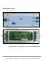
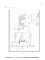
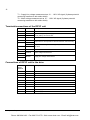
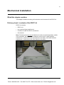
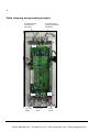
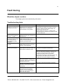
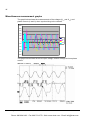
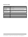
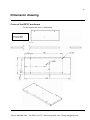
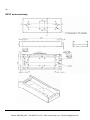
ACS800
User’s Manual
RSYC-01 Synchronizing Unit
Phone: 800.894.0412 - Fax: 888.723.4773 - Web: www.clrwtr.com - Email: [email protected]
Phone: 800.894.0412 - Fax: 888.723.4773 - Web: www.clrwtr.com - Email: [email protected]
RSYC-01 Synchronizing Unit
User’s Manual
Code: 3AFE68827370 REV A
EN
EFFECTIVE: 29.06.2007
FIDRI\EIF200
© 2007 ABB Oy. All Rights Reserved.
Phone: 800.894.0412 - Fax: 888.723.4773 - Web: www.clrwtr.com - Email: [email protected]
Phone: 800.894.0412 - Fax: 888.723.4773 - Web: www.clrwtr.com - Email: [email protected]
5
Table of contents
Table of contents............................................................................................................................ 5
Introduction to the manual ............................................................................................................ 7
What this chapter contains ............................................................................................................... 7
Compatibility..................................................................................................................................... 7
Safety instructions ............................................................................................................................ 7
Intended audience............................................................................................................................ 7
Other manuals.................................................................................................................................. 7
Description of operation and hardware ........................................................................................ 9
What this chapter contains ............................................................................................................... 9
Intended use of the RSYC unit ......................................................................................................... 9
Operation ......................................................................................................................................... 9
Overall view of the unit ................................................................................................................... 10
RSYC-01 unit with cover............................................................................................................ 10
RSYC-01 unit without cover ....................................................................................................... 10
Connection diagram ....................................................................................................................... 11
Terminals/connections of the RSYC unit ........................................................................................ 12
Connections of RSYC unit to the drive ........................................................................................... 12
Mechanical installation ................................................................................................................ 13
What this chapter contains ............................................................................................................. 13
Delivery check / contents of the RSYC kit....................................................................................... 13
Mechanical installation ................................................................................................................... 14
Mounting the RSYC unit ............................................................................................................ 14
Electrical installation.................................................................................................................... 15
What this chapter contains ............................................................................................................. 15
Connection diagram ....................................................................................................................... 15
Considerations ............................................................................................................................... 15
Cable clamping and grounding example......................................................................................... 16
Start-up ......................................................................................................................................... 17
What this chapter contains ............................................................................................................. 17
Parameter settings ......................................................................................................................... 17
Checking the operation of the RSYC unit ....................................................................................... 18
Checking of the trim function and synchronization.......................................................................... 19
Final check ..................................................................................................................................... 20
Disabling the synchronization ......................................................................................................... 20
Table of contents
Phone: 800.894.0412 - Fax: 888.723.4773 - Web: www.clrwtr.com - Email: [email protected]
6
Resetting the system.......................................................................................................................20
Fault tracing...................................................................................................................................21
What this chapter contains ..............................................................................................................21
Troubleshooting hints ......................................................................................................................21
Measuring with an oscilloscope .......................................................................................................22
Miscellaneous measurement graphs ...............................................................................................24
Technical data ...............................................................................................................................25
Dimension drawing .......................................................................................................................27
Cover of the RSYC enclosure .........................................................................................................27
RSYC enclosure body .....................................................................................................................28
Table of contents
Phone: 800.894.0412 - Fax: 888.723.4773 - Web: www.clrwtr.com - Email: [email protected]
7
Introduction to the manual
What this chapter contains
This chapter includes a description of the contents of the manual. In addition it
contains information about the compatibility, safety and intended audience.
Compatibility
The manual is compatible with RSYC-01 Synchronizing Unit. The drive parameter
data refers to ACS800 Standard Control Program.
Safety instructions
Follow all safety instructions delivered with the drive.
•
Read the complete safety instructions before you install, commission, or use the
drive. The complete safety instructions are given at the beginning of the drive
Hardware Manual.
•
Read the software function specific warnings and notes before changing the
default settings of the function. For each function, the warnings and notes given
in this manual in the section describing the related user-adjustable parameters.
Intended audience
This manual is intended for the people who are responsible for installing,
commissioning, using and trouble shooting the synchronization system with the
RSYC unit. The reader is expected to have knowledge of electrical fundamentals,
electrical wiring practices, electronic components, and electrical schematic
symbols. The person in charge of testing and commissioning a system this
complicated must be an experienced professional in the field of electrotechnics.
Other manuals
Hardware Manual of the drive.
ACS800 Standard Control Program 7.x Firmware Manual (3AFE64527592
[English]).
Introduction to the manual
Phone: 800.894.0412 - Fax: 888.723.4773 - Web: www.clrwtr.com - Email: [email protected]
8
Introduction to the manual
Phone: 800.894.0412 - Fax: 888.723.4773 - Web: www.clrwtr.com - Email: [email protected]
9
Description of operation and hardware
What this chapter contains
This chapter describes the operation of a synchronization application, shows a
connection diagram and presents the RSYC unit.
Intended use of the RSYC unit
A drive equipped with the RSYC unit is designed for applications in which a large
fixed-speed motor must be started to a weak supply line. Drive starts the motor
smoothly (no high starting current as with the direct on line start) simultaneously
generating a high torque. When the nominal speed (frequency) is reached, RSYC
unit verifies the status of the supply line and the drive output and controls the
switch-over contactors that shift the connection of motor from the drive to supply
line.
Operation
The RSYC unit monitors two voltage signals, one measured from the supply line
and other from the drive output. The signals indicate the phase shift and frequency.
The unit output signal (BUFOUT, 0 …10 V) indicates the synchronization status for
the drive. When the BUFOUT signal reaches 5 volts, the supply line and the drive
output voltages are synchronic, i.e. the phasing and frequency are the same.
The drive control program constantly corrects the drive frequency reference (set to
50 Hz) on basis of the BUFOUT signal by using the Trim function. When the
synchronizing conditions are reached, i.e. the drive output and the supply line
phasing’s match and the frequencies are equal:
•
BUFOUT signal reaches 5 volts indicating “synchronic” status for the drive
application program.
•
RSYC unit gives a control pulse for the contactor control circuitry.
•
Drive control logic switches the inverter modulation (IGBT control pulses) off.
•
Contactor control circuit opens contactor K1, disconnecting the motor from drive.
•
Contactor control circuit closes contactor K2, connecting the motor to the supply
line.
Description of operation and hardware
Phone: 800.894.0412 - Fax: 888.723.4773 - Web: www.clrwtr.com - Email: [email protected]
10
Overall view of the unit
RSYC-01 unit with cover
2)
3)
1)
RSYC-01 unit without cover
4)
4)
1) +24 V DC supply for the RSYC-01 unit
2) SYNC signal (K4) and BUF OUT signal
3) Inverter output (T2) and network supply (T1) measurement transformer signals
4) Cable screen clamps.
Description of operation and hardware
Phone: 800.894.0412 - Fax: 888.723.4773 - Web: www.clrwtr.com - Email: [email protected]
11
Connection diagram
Description of operation and hardware
Phone: 800.894.0412 - Fax: 888.723.4773 - Web: www.clrwtr.com - Email: [email protected]
12
T1 – Supply line voltage measurement as 10 … 120 V AC signal (3-phase potential
measuring transformer with static shield)
T2 – Motor voltage measurement as 10 … 120 V AC signal (3-phase potential
measuring transformer with static shield)
Terminals/connections of the RSYC unit
Terminal
Name
Description
1
+24 V
2
COM
Synchronizing unit power supply from the Motor Control and I/O
board (RMIO) via terminal X23.
J1
J2
1
2
3
SYNC
COM
COM
Output 0/24 V control pulse for external contactor control circuitry
BUFOUT
Output 0 … 10 V signals indicating the synchronization status for
the drive.
INVRTR
Motor voltage measurement
MAINS
Supply line voltage measurement
J3
1
2
3
4
Connections of RSYC unit to the drive
Name
Description
3
AI1+
Synchronization status indication
4
AI1-
Synchronization status indication
5
D15
Run enable
6
D16
Not in use
7
+24 V
24 V for run enable
1
+24 V
Power supply for RSYC
2
GND
Power supply for RSYC
RMIO
board
terminal
X21
X22
X23
Description of operation and hardware
Phone: 800.894.0412 - Fax: 888.723.4773 - Web: www.clrwtr.com - Email: [email protected]
13
Mechanical installation
What this chapter contains
This chapter contains mounting rail instructions and contents of the RSYC kit.
Delivery check / contents of the RSYC kit
RSYC kit contains:
•
RSYC unit
•
two synchronizing transformers
•
8 meters of cable for RSYC connections
•
this manual.
Note: Following items are not included but must be acquired separately: switchover contactors, the relays of the contactor control circuit, cable between
transformer T1 and main circuit (and fuses for the cable), and cable between
transformer T2 and main circuit (and fuses for the cable).
Mechanical installation
Phone: 800.894.0412 - Fax: 888.723.4773 - Web: www.clrwtr.com - Email: [email protected]
14
Mechanical installation
Mounting the RSYC unit
Mount the unit by snapping the feet onto a 7.5 × 35 mm mounting rail (1) (2).
Mounting
Mechanical instalation
Phone: 800.894.0412 - Fax: 888.723.4773 - Web: www.clrwtr.com - Email: [email protected]
15
Electrical installation
What this chapter contains
This chapter contains a reference to the connection diagram and a list of items to
consider in the electrical installation.
Connection diagram
See Connection diagram on page 11.
Considerations
Follow the cabling recommendations of the drive Hardware Manual.
Leave at least 0.5 m space between the unit and the power cables and drive
module. If 0.5 m is impossible, install as far as possible.
Use shielded twisted-pair cables between the transformers and the RSYC unit.
Ground the shields with as short pigtails as possible. Cut and insulate any unused
conductors at both ends of the cables. See Connection diagram.
Use shielded twisted-pair cables between the RSYC unit and the drive. Ground the
shields at the drive module end according to the instructions given in the drive
Hardware Manual.
Use shielded twisted-pair cables between the unit and the contactor control
circuitry. Ground the shields with as short pigtails as possible.
Dimension selects the cable in between the main circuit and the synchronizing
transformers according to the main circuit voltage. Protect the cable with fuses if
necessary.
Electrical installation
Phone: 800.894.0412 - Fax: 888.723.4773 - Web: www.clrwtr.com - Email: [email protected]
16
Cable clamping and grounding example
To network supply
measurement
transformer
To inverter output
supply measurement
transformer
J3
J2
J1
+24 V DC
supply
BUF OUT
signal
SYNC
signal
Electrical installation
Phone: 800.894.0412 - Fax: 888.723.4773 - Web: www.clrwtr.com - Email: [email protected]
17
Start-up
What this chapter contains
This chapter instructs in setting the drive parameters and in checking the system.
Parameter settings
The table below instructs in parameter settings for a drive with ACS800 Standard
Control Program starting a four-pole motor (50 Hz). With these settings, the trim
control can affect ±20 rpm to final speed reference (1% of the defined maximum
speed limit). Here, the panel will be used as the external control signal interface.
That is the recommended practise at the start-up. Change later to I/O or fieldbus
control if needed. However note that analogue input AI1 and digital input DI5 are
reserved for the synchronization application.
Before starting, ensure that the contactor control circuit connection at terminal J2 of
the RSYC unit is disconnected.
For the use of control panel, see ACS800 Standard Control Program 7.x Firmware
Manual (3AFE64527592 [English]).
Setting
Parameter value
Additional information
Selecting control location and signal sources
Select external control location EXT2
into use.
11.02 = EXT2
Define control panel for source of
control commands for external control
location EXT2.
10.02 = KEYPAD
Define control panel for source of
speed reference for external control
location EXT2.
11.06 = KEYPAD
Fix rotation direction of motor to
forward.
10.03 =
FORWARD
Deactivate constant speed selections.
12.01 = Inactive
Set digital input DI5 to source for run
enable signal.
16.01 = DI5
See section Connection diagram on page 11.
Define maximum and minimum limits
for the motor speed.
20.01 = 0.00 rpm
Maximum speed must be higher than motor
nominal speed. 2000 is suitable value for a 4pole, 50 Hz motor.
Define the stop mode for the run
enable function.
20.02 = 2000.00
rpm
20.07 = COAST
Trim function can be used only with % reference
(REF2). REF2 can be given from various
interfaces. Here, control panel (KEYPAD) will be
used.
Change of direction is disabled.
The drive will cut off output voltage immediately
after run enable is switched off.
Settings of PID controller used by Trim function, Parameter group 40
Activate error value inversion.
40.05 = YES
RSYC unit feature.
Activate ACT1 for PID controller.
40.06 = ACT1
-
Start-up
Phone: 800.894.0412 - Fax: 888.723.4773 - Web: www.clrwtr.com - Email: [email protected]
18
Setting
Parameter value
Additional information
Select analogue input AI1 for actual
signal for PID controller.
40.07 = AI1
BUF OUT signal from RSYC unit, 0 … 10 V.
Below 5 V = supply line frequency exceeds drive
output frequency.
5 V = Supply line frequency and drive output
frequency are equal and phases match.
Above 5 V = supply line frequency is lower than
drive output frequency
Set minimum value for ACT1.
40.09 = 0.00%
-
Set maximum value for ACT1.
40.10 = 100.00%
-
Deactivate integration term of PID
controller.
40.13 = OFF
-
Activate Trim function and define
trimming relative to maximum speed.
40.14 = DIRECT
PID controller output is relative to maximum
speed limit (Par. 20.02).
Select parameter 40.16 for the source
of the trim reference.
40.15 = PAR
40.16
Set trim reference to 50%.
40.16 = 50.00%
Trim reference is equal to actual signal when the
synchronization conditions are valid i.e. when
AI1= 5 V. See parameter 40.07 above.
Define the maximum effect of trim (that
is added to the drive reference)
40.17 = 1.00%
-
Macro selection and motor control mode
Select factory macro.
99.02 =
FACTORY
Other macros except PID CNTRL are also
possible (PID cannot be used as the PID
controller is reserved for Trim function).
Select motor control mode.
99.04 = DTC
-
Define the motor parameters.
99.05 …99.10
See ACS800 Standard Control Program 7.x
Firmware Manual (3AFE64527592 [English]).
Checking the operation of the RSYC unit
WARNING! Read and follow the instructions in the drive Hardware Manual. Ignoring
the instructions can cause physical injury or death, or damage to the equipment.
Ensure that the drive is disconnected from the supply line and all other precautions
described in the safety instructions have been taken into consideration.
Before starting, ensure that the contactor control circuit connection at terminal J2 of
the RSYC unit is disconnected.
For the use of control panel, see ACS800 Standard Control Program 7.x Firmware
Manual (3AFE64527592 [English]).
Start-up
Phone: 800.894.0412 - Fax: 888.723.4773 - Web: www.clrwtr.com - Email: [email protected]
19
Action
Additional information
Check unit visually.
-
Set drive parameters according to instructions. However,
switch Trim function off (parameter 40.14 = OFF) for the time
being.
See Parameter settings on page 17.
Shift control panel to local control mode.
Use LOC/REM key. Letter L on first row of display
indicates local control.
Select following actual values to panel display: 01.02
SPEED, 01.03 FREQUENCY, 01.18 AI1 [V].
AI1 is the 0 … 10 V DC status signal from the
unit.
Start drive and increase speed reference until output
frequency is as close to 50 Hz as possible. Write down actual
speed and speed reference at 50 Hz output frequency.
The difference between the speed reference and
the actual speed depends on the slip which, in
turn, depends on the motor load.
Drop speed so that output frequency is 45 … 47 Hz. Ensure
that AI1 is 8 … 10 V DC.
-
Increase speed reference so that output frequency is
52 … 55 Hz. Ensure that AI1 is 0 … 1 V DC.
-
Stop the drive.
-
Checking of the trim function and synchronization
This check makes sure that the trim function affects the speed control of the drive in
the correct manner. Finding a right value for trim range adjustment (parameter
40.17) is essential for stable control and fast synchronization. Then the system
reaches the synchronization with decreasing oscillations around 50 Hz and actual
signal for Trim function (AI1) settles to approximately 5 V DC.
For the use of control panel, see ACS800 Standard Control Program 7.x Firmware
Manual (3AFE64527592 [English]).
Reserve at hand the value of the speed reference and actual speed that were
equivalent to 50 Hz output frequency (defined in the previous section). Checking
the operation of the RSYC unit on page 18.
Actions
Information
Set drive parameters according to instructions. However, switch Trim function off
(parameter 40.14 = OFF) for the time being.
See Parameter settings on page 17.
Use LOC/REM key to select remote control. The drive is now ready to be
controlled externally with the control panel.
Letter R on first row of display
indicates remote control mode of
panel.
Start drive.
-
Set speed reference to value that was equivalent to 50 Hz output frequency.
-
Check output frequency from display. If it is not 50 Hz adjust the reference in
small steps so that output frequency from display shows 50 Hz. Write down this
value again.
-
Stop drive.
-
Set trim function on (parameter 40.14 TRIM MODE = DIRECT).
The speed reference and output
frequency will now be affected by
Trim function slightly.
Start-up
Phone: 800.894.0412 - Fax: 888.723.4773 - Web: www.clrwtr.com - Email: [email protected]
20
Actions
Information
Start drive and monitor panel and RSYC status LED. The following indicates
successful Trim control loop:
- Drive accelerates to speed reference which was defined above.
- Output frequency starts oscillating around 50 Hz.
- AI1 is 2.5 V … 7 V.
- RSYC LED blinks the first time after 5 … 20 seconds.
- LED starts blinking in shorter time intervals and finally LED illuminates steady
for several seconds.
-
Increase 40.17 TRIM RANGE ADJUST slightly (e.g. 1 … 5%) if faster
synchronization is required.
Excessive value may lead to
unstable control.
Stop drive.
Final check
Action
Additional information
Connect the contactor control circuit cable (J2/SYNC) to RSYC unit.
-
Test the system and verify the operation.
-
The system will synchronize in less than 15 seconds and will remain in the
synchronization status for tens of seconds when it is properly installed and
commissioned.
Disabling the synchronization
To disable synchronization function:
•
Change the external control location in the drive application program from EXT2
to EXT1 (parameter 11.02) or switch the drive to local control mode by the
LOC/REM key of the control panel.
•
Turn operating switch S1 in the contactor control circuit to the OFF position.
Resetting the system
The relay logic can be reset to initiate another synchronizing cycle by turning the
operating switch S1 of the contactor control circuit to the OFF position and then to
ON again (1-0-1).
Start-up
Phone: 800.894.0412 - Fax: 888.723.4773 - Web: www.clrwtr.com - Email: [email protected]
21
Fault tracing
What this chapter contains
This chapter gives the troubleshooting information.
Troubleshooting hints
Trouble
Cause
Remedy
Unit operates illogically
despite all connections and
parameters are correct.
The board is affected by radiated
interference. BUF OUT signal is not
stable and as a consequence
synchronization is not possible.
Ensure all cables that connect to the RSYC unit
are shielded and shields are properly grounded.
Install an additional metal shield between the
emission source and the unit.
Change location of the unit, i.e. arrange more
space between the emission source (drive module
or motor cables) unit.
BUF OUT signal from
RSYC board is constantly
low i.e.0 … 1 V DC.
Signals from synchronizing
transformers are cross-connected at
the RSYC unit.
Check and correct connections.
Drive output frequency
remains too close to 50 Hz
and occasional short
synchronization pulses
take place.
Too small value for parameter 40.17
TRIM RANGE ADJUST. Drive
cannot control the speed (and output
frequency) loosely enough.
Increase the value of parameter 40.17.
The speed control is
unstable.
Too large value for parameter 40.17
TRIM RANGE ADJUST causes the
control to overcompensate.
Decrease the value of parameter 40.17.
Excessive motor current
peak at synchronization.
Rotor decelerates too fast and
phase difference between stator and
motor fluxes increase too much.
Make contactors operate faster if possible.
Contactors can operate simultaneously.
Connect a serial inductor (3 phase choke) to the
motor AC input during switching of change-over
contactors. Equip the choke with a by-pass
contactor (the choke does not need to be
dimensioned according to continuous current, only
the contactor). The choke must not saturate
through. See Connection diagram on page 11.
Motor flux decreases too much
during the operation of change-over
contactors. High current is needed to
remagnetize the motor.
Check and correct the transformer connection.
Supply line (motor) and drive output
are 180º out of phase due to wrong
connection of the synchronization
transformer.
Check and correct the transformer connection.
Supply line and drive output are 180º
out of phase since the phasing
between motor and supply line
differs from the phasing between
motor and drive output.
Check and change the connections.
Fault tracing
Phone: 800.894.0412 - Fax: 888.723.4773 - Web: www.clrwtr.com - Email: [email protected]
22
Measuring with an oscilloscope
Checking the supply line (MAINS) and inverter output (INVRTR) signals from the
board may be the only way to see what is actually happening if there is no SYNC
signal. There is a potential interference risk as it is possible that the probes pick-up
the interference and conduct it to the board circuits. All loops should be kept as
small as possible and measuring circuits should be routed as far away from the
drive and other cables as possible. The following figure shows the measuring points
TP3 – TPVREF and TP4 - TPVREF.
Fault tracing
Phone: 800.894.0412 - Fax: 888.723.4773 - Web: www.clrwtr.com - Email: [email protected]
23
When the signals are in synchronization, the oscilloscope shows the following
waveforms.
When there is a phase difference, the waveforms are as shown in the graphic
below.
When the frequencies are different, the signals move respective to each other. If
the “speed” is low enough, the board may generate a SYNC pulse.
Fault tracing
Phone: 800.894.0412 - Fax: 888.723.4773 - Web: www.clrwtr.com - Email: [email protected]
24
Miscellaneous measurement graphs
The graph below shows the measurements of the voltages (Uu-v and Uv-w) and
phase currents (Iu and Iw) when synchronizing to the network.
1200
1000
800
600
400
Iu
Uu-v
200
Iw
0
-200
1
96 191 286 381 476 571 666 761 856 951 1046 1141 1236 1331 1426
Uv-w
-400
-600
-800
-1000
The graph below shows the drive output voltage, network voltage and one phase
current.
Fault tracing
Phone: 800.894.0412 - Fax: 888.723.4773 - Web: www.clrwtr.com - Email: [email protected]
25
Technical data
RSYC power supply voltage
24 V DC (-5 … +5%)
RSYC power consumption
25 … 35 mA
Signal cable type
Signal cable size
Signal cable use
JAMAK by NK Cables
2
2 × (2+1) × 0.5 mm
Connection of the RSYC unit to the drive, transformers and control relays
Synchronization accuracy
-21 … +21º
Transformer cable size
Transformer cable use
Max. cross-section = 4 mm
Connection between the measuring transformers and main circuit (at drive output
and input).
Mounting rail
7.5 × 35 mm (EN50022)
Measuring transformer
e.g. 3AFE58125130, 690/43.3 V, 3 VA, 45 … 65 Hz
Primary voltage
690 V AC 45 …65 Hz
Secondary voltage
43,3 V AC 45 … 65 Hz
Power
3 VA
Winding connection
Dyn 11
Winding separation
Static screen
2
Technical data
Phone: 800.894.0412 - Fax: 888.723.4773 - Web: www.clrwtr.com - Email: [email protected]
26
Technical data
Phone: 800.894.0412 - Fax: 888.723.4773 - Web: www.clrwtr.com - Email: [email protected]
27
Dimension drawing
Cover of the RSYC enclosure
The dimensions are given in millimetres.
Dimension in mm.
1 mm = 0.039”
1” = 25.4 mm
Dimension drawing
Phone: 800.894.0412 - Fax: 888.723.4773 - Web: www.clrwtr.com - Email: [email protected]
28
RSYC enclosure body
Dimension drawing
Phone: 800.894.0412 - Fax: 888.723.4773 - Web: www.clrwtr.com - Email: [email protected]


![[ENG] EVO DSP TM 10-30 kVA User Manual v. 2.0](http://vs1.manualzilla.com/store/data/005715238_1-26b73917878f712f842422018d03a475-150x150.png)