1
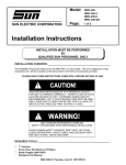
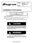
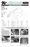
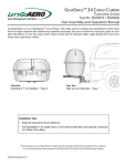
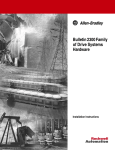
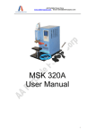
Model:
EEAC319/320A
KOOL KARE Xtreme ™
UNIT SETUP
Page:
1 of 4
Installation Instructions
INSTALLATION MUST BE PERFORMED
BY
QUALIFIED PERSONNEL ONLY
INSTALLATION OVERVIEW: ______________________________________________
The Installation Procedure listed is for the Snap-on KOOL KARE Xtreme™ (EEAC319/320A). The unit is
shipped as a fully assembled unit, with the exception of the items listed in the Parts & Accessories.
PLEASE READ THESE INSTRUCTIONS COMPLETELY BEFORE SETTING UP UNIT
PARTS & ACCESSORIES:________________________________________________
PART NUMBER
1-15080
1-19281A
1-27180
1-27280
1-05585A
1-05685A
1-07184A
1-42401A
8-1163
8-1263
EAA0275L05A
EAH0001C01A
EAH0001C02A
EAH0040L22A
TEEAC319A0
ZEEAC319A
DESCRIPTION
Adapter, Low Side
Filter Assembly, Particle
Adapter, Service, High Side
Adapter, Service, Low Side
Bottle, Disposable 8oz.
Bottle, Pump Oil Refill - EEAC319 only
Support, vibration control
Screw, 10-32 x 1.25" Hexhead
Equipment Certificate
Technician Certificate
Recovery Tank Assembly (R-134a)
Red Hose
Blue Hose (EEAC319A Only)
Blue Hose w/Vacuum Pump Port (EEAC320A Only)
Installation Instructions
User’s Manual
QTY
1
1
1
1
2
1
1
1
1
1
1
1
1
1
1
REQUIRED TOOLS: _____________________________________________________
•
•
•
•
Safety Goggles
R-134a Virgin Tank (Supplied by Customer)
Gloves
5/6" Nut driver
TEEAC319A0 (10/13/2005) REV C.
Page 2 of 4
!
THIS UNIT MUST BE PLUGGED INTO A PROPER AC OUTLET FOR UNIT
TO OPERATE CORRECTLY. REFER TO THE UNIT ID PLATE LOCATED
ON BACK OF UNIT. EXTENSION CORDS ARE NOT RECOMMENDED,
BUT IF AN EXTENSION CORD MUST BE USED, USE A CORD THAT IS
LESS THAN 50 FEET WITH A 16 AWG, OR ABOVE 50 FEET AND LESS
THAN 100 FEET WITH A 14 AWG.
!
USE STANDARD REFRIGERANT HANDLING
SAFETY PROCEDURES WHEN PERFORMING INSTALLATION
ALWAYS WEAR SAFETY GOGGLES, DON’T SPILL OR TOUCH LIQUID
REFRIGERANT, AVOID FLAMES, AND EXCESSIVE HEAT. USE ONLY IN
WELL-VENTILATED AREA.
PARTS & ACCESSORIES SETUP __________________________________________
1. Remove the Blue and Red Hoses from the box. Remember to OIL the seals on each end of the
hoses.
2. If necessary, connect the high (red) and low (blue) couplers to their respective hoses. Rotate
coupler knobs fully CCW (closed).
3. Attach other end of the blue hose to lower, blue labeled (low side) port on the back panel of the
KOOL KARE Xtreme™ unit. Dress hose down to the right side of the unit.
4. Attach other end of the red hose to upper, red labeled (high side) port on the back panel of the
KOOL KARE Xtreme™ unit. Dress hose down to the right side of the unit.
5. Find threaded insert located on cabinet above and to the right of the tank and secure hoses to
the cabinet with the hose clamp (1-07184A) and screw (1-42401A) provided.
6. Install plastic oil bottles (1-05585A) to the white caps mounted in the front of the unit.
7. Remove the User's Manual, MAC Form/Certification, Product Registration Form, and Warranty
Registration from the box. Hand these items to the Owner or Manager.
8. Remove Recovery Tank (EAA0275L05A) from its box. Remove cardboard wrap from Recovery
Tank and set on floor.
9. Remove cardboard from scale plate.
10. Check and tighten hose fittings that connect to Master Filter/Dryer.
TEEAC319A0 (10/13/2005) REV C.
Page 3 of 4
PREPARING RECOVERY TANK: __________________________________________
1. Referring to FIGURE 1, open the BLUE valve on
Recovery Tank to release ALL COMPRESSED AIR.
2. Install Particle Filter (1-19281A) on blue valve port of
Recovery Tank.
3. Gently set the Recovery Tank on the scale.
4. Rotate the tank so the valves face towards the rear of
the unit.
Blue
Hose
Particle
Filter
5. Place the strap around the Recovery Tank.
6. Install the supplied tank adapter 1-15080 on the
Particle Filter installed in step 2.
7. Attach the blue vehicle hose w/adapter to the Low side
of the tank (Adapter). Open Service Adapter by
turning fully clockwise.
FIGURE 1 RECOVERY TANK
8. Plug AC Cord to a proper 115VAC outlet. And turn-on the unit by the rear panel switch.
NOTE: In the unlikely event, the LCD screen is unreadable upon power up, adjust LCD
contrast. Refer to the user’s manual for contrast adjustment.
9. Press the Down Arrow Button until Arrow on display is pointing to “VACUUM”.
a. Press <ENTER>.
b. Press the Down arrow until desired amount of vacuum time is displayed (15 minutes).
c. Press <NEXT>.
d. Turn the front panel valve to LOW.
e. Press <START>, vacuum pump should turn ON in about 5 seconds.
10. The low side gauge shows vacuum increasing.
11. Monitor low side gauge until a minimum of 25 inches has been reached.
12. Once completed, close the Recovery Tank valve (BLUE). Close the blue Service Adapter.
13. Press <EXIT>. Close panel valve. Press <NEXT> Main Menu appears.
14. Remove the blue vehicle hose w/adapter from the tank.
NOTE: Remove the R-134a tank adapter, (1-15080) and place in the storage tray.
15. Identify the three hoses leading from the bottom of the unit. Connect the yellow hose to the tank
purge port.
16. Identify the blue hose leading from the bottom of the unit. Connect hose with the anti-blowback
valve to the Particle Filter on the blue (liquid) valve of the Recovery Tank.
17. Identify the red hose leading from the bottom of the unit. Connect hose with the anti-blowback
valve to the red (vapor) valve of the Recovery Tank.
18. Open both red and blue valves on tank. Unit is ready for operation.
Refer to the user’s manual for pre-charging tank.
Refer to next page for first time fast charge.
INSTALLATION COMPLETE
TEEAC319A0 (10/13/2005) REV C.
Page 4 of 4
PRE-CHARGING RECOVERY TANK USING GRAVITY METHOD:
NOTE: THIS PROCEDURE IS USED TO SETUP THE UNIT FOR CHARGING. RECOVERY TANK
SHOULD HAVE AT LEAST A 25” VACUUM. THIS PROCEDURE IS DONE WHEN
RECOVERY TANK IS ON THE SCALE
1. Plug unit in and turn on. Press <AMOUNTS>, then press <MORE> to read chargeable amount.
2. Be sure Recovery Tank valves (B) are closed and
tank is in vacuum on scale. Refer to FIGURE 2.
3. Disconnect the Blue hose from the Recovery Tank.
4. Disconnect and Re-Oil both of the seals on blue
service hose (C). Connect the finger tight Acme
thread connector of the blue service hose to the
Virgin Tank (A).
5. If not already done, connect the Low Side Adapter
(1-15080) to the particle filter on the blue side of the
Recovery Tank.
6. Connect the service coupler of the blue service hose
to the Low Side Adapter on the Blue Valve on the
Recovery Tank (B).
A
7. Open the blue Valve on the Recovery Tank.
8. Raise the Virgin Tank to a higher level than the
Recovery Tank. Invert the Virgin Tank (A) and open
valve.
C
9. Gravity and vacuum will transfer the liquid refrigerant
to the Recovery Tank faster than recovering it.
NOTE: THE SCALE WILL NOT START READING
UNTIL ABOUT 3 Lbs. OF REFRIGERANT HAS
“PRIMED” THE TANK.
B
NOTE: DO NOT OVER CHARGE TANK. THE SAFE
AMOUNT TO CHARGE IS AROUND 15 LBS.
10. After the desired amount of refrigerant has been
transferred, close valves on Virgin Tank first, pause
FIGURE 2 CHARGING TANK
to allow refrigerant to flow into the Recovery Tank,
then close Recovery Tank valve. Set Virgin Tank on ground upright.
11. Close service coupler (CCW) and disconnect from tanks. Remove the Low Side Adapter from
the Recovery Tank. Slowly loosen hose fitting from Virgin tank allowing vapor to escape.
12. Re-Oil seals on anti-blow back valve on the blue Hose from unit and connect to Recovery Tank.
Open both Recovery Tank valves.
13. Re-Oil seals on blue service hose. Connect the end opposite the service coupler of the Blue
hose to the Low side bulkhead fitting.
14. Unit is ready to recover and charge refrigerant.
REMEMBER TO OIL O-RINGS AND SEALS
WHEN ATTACHING HOSES OR FITTINGS
TEEAC319A0 (10/13/2005) REV C.