1
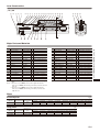
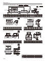
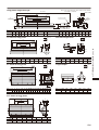
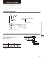
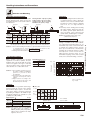
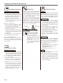
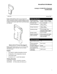
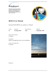
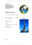
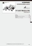
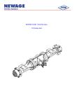
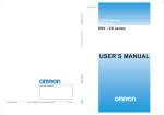
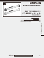
CAD drawing data catalog
is available.
ACTUATORS GENERAL CATALOG
SLIT TYPE RODLESS
CYLINDERS φ63, φ80
Features/Specifications/Order Codes
Inner Construction, Major Parts and Materials
Dimensions
Sensor Switches
Handling Instructions and Precautions
Caution
1123
1124
1125
1128
1130
Before use, be sure to read the “Safety Precautions” on p. 57.
1122
SLIT TYPE RODLESS CYLINDERS φ63, φ80
CONTENTS
RODLESS CYLINDERS
φ63,φ80
Features
Specifications
● A long stroke of up to 5000mm [196.8in.] can be manufactured. It
can also be used to make driving equipment, which could not be
done by air cylinders in the past.
● The magnet for the sensor switch is standard equipment. By
installing a sensor switch, the piston position can be easily
detected, and the space for the limit switch mounting and design
man-hours can be greatly reduced.
● Upside down installation mountings have been put into a series.
By installing the piston yoke facing downwards, the seal band is
protected, thereby increasing its durability.
φ63 [2.480in.]
Bore size
Operation type
Double acting type
Operating pressure range MPa [psi.]
0.1∼0.8 [15∼116]
Proof pressure
Operating speed range mm/s [in./sec.]
100∼1500 [3.9∼59.1] Note1
Required Note2
Lubrication
Rc3/8
Maximum stroke
mm [in.]
Rc1/2
5000
mm
1000 or less
Stroke tolerance
Rodless cylinder with sensor
0∼60 [32∼140]
Both sides (Variable cushion)
Cushion
Port size
Rodless cylinder
1.2 [174]
MPa [psi.]
Operating temperature range °C [°F]
Symbols
φ80 [3.150in.]
Air
Media
1001∼3000
3001∼5000
+2
+0
+3
+0
+4
+0
[+0.079
+0.039 ]
[+0.118
+0.039 ]
[+0.157
+0.039 ]
Notes: 1. Consult us when the cylinder speed exceeds 1500mm/s
[59.1in./sec.].
2. However, it is not required for a cylinder speed of 500mm/s
[19.7in./sec.] or less. For the recommended oil, see the
recommended oil list.
Remark: For details of sensor switches, see p.1544.
Order Codes
ORC
63 ×800 −
Rodless
cylinder
Bore size
×
Stroke
Fluoro rubber specification
Blank Standard
F
Fluoro rubber
specification
Piston specification
Blank Standard piston
L
Long piston
−
−
● Since a magnet is already standard on the rodless cylinders,
mounting a sensor switch will enable use in sensor switch
applications.
−
Number of
adapters
1
With 1
2
With 2
⋮
⋮
Lead wire length
A
1000mm [39in.]
B
3000mm [118in.]
Adapter
Blank No adapter
U
U type adapter
G
G type adapter
(onlyφ80)
(onlyφ63)
Sensor switch (For the cylinder with sensor)
Blank
No sensor switch
ZG530
2-lead wire Solid state type with indicator lamp
ZG553
3-lead wire Solid state type with indicator lamp
CS3M
2-lead wire Reed switch type with indicator lamp
CS4M
2-lead wire Reed switch type with indicator lamp
CS5M
2-lead wire Reed switch type without indicator lamp
Mounting bracket
Blank
No mounting bracket
Mount for piston mount
Blank
No mount
L
With foot mounting bracket
T
With T mount (For standard piston)
M
With M mount (For standard piston)
C
With C mount (For standard piston)
CT
With CT mount (For standard piston)
CM
With CM mount (For standard piston)
LT
With LT mount (For long piston)
CL
With CL mount (For long piston)
CLT
With CLT mount (For long piston)
●The mount for piston mount, the mounting bracket, and the adapter are included at shipping.
Bore Size and Stroke
63
Available strokes
500, 600, 700, 800, 1000
1200, 1400, 1600, 1800, 2000
100∼5000Note
80 Manufactured upon receipt of order
Remark: Non-standard strokes are available at 1mm pitch intervals. For delivery, consult us.
Note: Consult us for strokes over 5000mm.
1123
DC10∼28V
DC4.5∼28V
DC10∼30V, AC85∼115V
DC10∼30V, AC85∼115V
DC3∼30V, AC85∼115V
● Order codes for sensor switch only
Without holder ·····
With holder ···········
− ORC
Bore size
★ The order code for the
holder only is
G5-ORC Bore size .
With holder for rodless
cylinder
Lead wire length
A
1000mm [39in.]
B
3000mm [118in.]
Sensor switch
mm
Standard strokes
Bore
Number of sensor switches
(For the cylinder with sensor)
1
With 1 sensor switch
2
With 2 sensor switches
⋮
⋮
● For details of sensor switches, see p.1544.
Inner Construction
φ63,φ80
q−w
e r t
y−u i o !0 !1 !2 !3 !4 !7 !8 @0 @1 @2 @3 @4 @5
!5 !6 @6 @7
A
Section A-A'
A'
@8
@9
#0
#1
#2 #3
#4
!9
Major Parts and Materials
Number
Aluminum (anodized)
1
w End cover L Note2
K
Aluminum (anodized)
1
Parts
Remarks
Materials
Number
!8
K
Piston mount
Aluminum (anodized)
1
!9
K
Magnet
Alnico magnet
2
@0
K
Piston yoke setscrew
Alloy steel
No.
Parts
Remarks
For standard or long piston
e Inner seal band setscrew Alloy steel
K
4
4
8 pieces for a long piston type
r Inner seal band lock
K
Aluminum (anodized)
2
@1
K
Piston yoke
Aluminum (anodized)
1
For standard or long piston
t Cushion needle
K
Steel
2
@2
K
Piston axle
Aluminum (anodized)
1
For standard or long piston
@3
K
Wear ring
Polyethylene
2
Hexagon socket setscrew
y Outer seal band setscrew Alloy steel
K
4
u Cap
K
Nylon
2
@4
K
End plate
Aluminum (anodized)
2
i Outer seal band lock
K
Steel
2
@5
K
Aluminum (anodized)
2
o Lock ring
K
Zinc alloy
2
@6
K
Piston end
Mount fixing bolt
Alloy steel
2
!0 Cap ring
K
Aluminum (anodized)
2
@7
K
Mount fixing nut
Alloy steel
2
!1 Pin
K
Steel
6
@8★ Cushion gasket
K
Synthetic rubber (NBR)
2
FPM for fluoro rubber specification
!2 Cushion pipe
K
Aluminum (anodized)
2
@9
K★ Cylinder gasket
Synthetic rubber (NBR)
2
FPM for fluoro rubber specification
!3 Outer seal band
K
Stainless chrome steel
1
For standard or long piston
#0
K★ Cushion seal
Synthetic rubber (NBR)
2
FPM for fluoro rubber specification
!4 Inner seal band
K
Stainless chrome steel
1
For standard or long piston
#1
K★ Piston seal
Synthetic rubber (NBR)
2
FPM for fluoro rubber specification
!5 Cylinder barrel
K
Aluminum (anodized)
1
For standard or long piston
#2
K
Synthetic rubber (CR)
1
For standard or long piston
!6 Magnet strip
K
Rubber magnet
2
For standard or long piston
#3
K★ Scraper
Polyacetal
2
#4
K★ Bearing strip
Polyethylene
4
!7 Piston mount setscrew Alloy steel
K
Slotted countersunk head screw
2
Remark: Specify the bore size and the piston specification when ordering the
parts.
Notes: 1. The end cover of ORC63 can be used for right and left ends.
In the case of ORC80, when facing connection ports, this is the left
side one.
2. The end cover of ORC63 can be used for right and left ends.
In the case of ORC80, when facing connection ports, this is the
right side one.
Scraper holding O-ring
Hexagon socket head bolt
8 pieces for a long piston type
★: Available as a seal repair kit.
Mass
Standard piston
Bore size
mm [in.]
kg [lb.]
Zero stroke mass Additional mass for
each 1mm [0.0394in.]
(With short mount)
stroke
Additional mass of mount for piston mount, mounting bracket, and adapter
T mount
M mount
C mount
CT mount
CM mount
63 [2.480]
9.3 [20.5]
0.0080 [0.0176]
0.2 [0.4]
1.0 [2.2]
2.4 [5.3]
2.6 [5.7]
3.4 [7.5]
0.3 [0.7]
1.7 [3.7]
1.7 [3.7]
80 [3.150]
16.1 [35.5]
0.0128 [0.0282]
0.6 [1.3]
1.2 [2.6]
4.3 [9.5]
4.9 [10.8]
5.5 [12.1]
0.6 [1.3]
2.9 [6.4]
3.3 [7.3]
Long piston
Bore size
mm [in.]
Foot mounting bracket U type adapter G type adapter
kg [lb.]
Zero stroke mass Additional mass for
each 1mm [0.0394in.]
(With long mount)
stroke
Additional mass of mount for piston mount, mounting bracket, and adapter
LT mount
CL mount
63 [2.480]
13.9 [30.6]
0.0080 [0.0176]
0.7 [1.5]
5.2 [11.5]
CLT mount Foot mounting bracket U type adapter G type adapter
5.9 [13.0]
0.3 [0.7]
1.7 [3.7]
1.7 [3.7]
80 [3.150]
23.2 [51.2]
0.0128 [0.0282]
1.2 [2.6]
8.8 [19.4]
10.0 [22.1]
0.6 [1.3]
2.9 [6.4]
3.3 [7.3]
1124
SLIT TYPE RODLESS CYLINDERS φ63, φ80
Materials
q End cover R Note1
K
No.
Dimensions
(mm)
Standard piston, short mount type
Bore size ×
ORC
Note : The connection port can be located on the bottom.
For details, consult us.
Stroke
A+Stroke
B
ORC- Bore size
Stroke
C
D
X
2-φP
E
I
Y
2-Cushion needle
8-R
Mounting thread
J
M
K
H
□T
φU
L
N
O
Connection port
□S
G
Code
Bore
mm [in.]
B
C
D
E
G
H
I
J
K
L
M
N
O
P
R
S
T
U
X
Y
63 [2.480] 430
215
220
180
90
82
53
30
19
83
78
68
20
4-Rc3/8
9
M8×1.25 Depth20
106
78
88
8
10
80 [3.150] 520
260
280
240
120
102
66
32
20
101
95
83
25
2-Rc1/2
11
M10×1.5 Depth25
132
96
112
10
13
T mount for standard piston
CT mount for standard piston
ORC-ST
CC
C
TC
TJ
TJ
TK
CS
TT
4-φTQ
TE
TI
4-φTQ
TE
TI
TT
A
Code
Bore
mm [in.]
C
TC
TE
TI
TJ
TK
TQ
TT
Code
Bore
mm [in.]
CC
CS
TE
TI
TJ
TQ
TT
63 [2.480]
220
208
130
80
60
89
9
7
63 [2.480]
208
123
130
80
60
9
7
80 [3.150]
280
268
180
100
75
108
11
8
80 [3.150]
268
150
180
100
75
11
8
CM mount for standard piston
MC
MI
4-φMQ
MH
MR
CU
CT
MH
MX
Movable range
MK
MM
MR
MX
MJ
MX
MJ
MT
ME
MI
4-φMQ
ME
MX
MT
MC
MX
ORC-SM
MX
Movable range
M mount for standard piston
MC
ME
MH
MI
MJ
MK
MM
MQ
MR
MT
MX
Code
Bore
mm [in.]
MC
ME
MH
MI
MQ
MR
MT
MX
63 [2.480] 120
100
48
90
70
100
70
9
10
6
10
63 [2.480]
134 104.5 120
100
48
90
9
10
6
10
80 [3.150] 150
125
60
110
85
122
86
11
13
8
12
80 [3.150]
163
125
60
110
11
13
8
12
D
I
Code
Bore
mm [in.]
C mount for standard piston
CT
CU
128
150
ORC-CS
CC
D
I
2-φP
CH
CM
CG
M
CI
L
CF
K
CL
J
CK
E
CJ
Code
Bore
mm [in.]
M
P CC CF CG CH CI CJ CK CL CM
63 [2.480] 180 90 30 19 83 78 68
E
J
K
L
9 208 62 71 82 15°77 117 112 102
80 [3.150] 240 120 32 20 101 95 83 11 268 78 88 102 15°96 143 137 125
1125
Note: The connection port can be located on the bottom.
For details, consult us.
Long piston, long mount type
LA+Stroke
LB
ORC-LONG
2-φP
LC
LD
X
I
Y
8-R
Mounting
thread
J
2-Cushion needle
H
□T
φU
K
LE
M
N
L
O
Connection port
□S
G
Code
Bore
mm [in.]
G
H
I
J
K
L
M
N
O
P
R
S
T
U
X
Y
LA
LB
LC
LD
LE
63 [2.480]
82
53
30
19
83
78
68
20
4-Rc3/8
9
M8×1.25 Depth20
106
78
88
8
10
730
365
480
400
200
80 [3.150] 102
66
32
20
101
95
83
25
2-Rc1/2
11
M10×1.5 Depth25
132
96
112
10
13
820
410
560
480
240
LT mount for long piston
Foot mounting bracket
ORC-LT
ORC-FOOT
LC
LG
8-φTQ
TI
AF
AG
AD
4-φAP
AE
Code
Bore
mm [in.]
LC
LF
LG
TE
TI
TJ
TK
TQ
TT
Code
Bore
mm [in.]
AD
AE
AF
AG
AH
AP
AT
63 [2.480]
480
260
468
130
80
60
89
9
7
63 [2.480]
30
104
48
15
57
11
40
80 [3.150]
560
360
548
180
100
75
108
11
8
80 [3.150]
35
130
60
17.5
72
14
50
CL mount for long piston
U type adapter
ORC-CL
2-φP
LG
LD
ORC-U
I
LE
CG
M
CI
L
UB
K
UK
UJ
CM
CF
CH
CK
CL
J
4-φUD
UC
UF
UG
CJ
Code
Bore
mm [in.]
Code
Bore
mm [in.]
UB
UC
UD
UF
UG
UJ
UK
62 71 82 15° 77 117 112 102 400 200 468
63 [2.480]
190
210
11
95
114
57
10
80 [3.150] 32 20 101 95 83 11 78 88 102 15° 96 143 137 125 480 240 548
80 [3.150]
235
260
14
120
144
72
12
I
J
K
L
M
63 [2.480] 30 19 83 78 68
P CF CG CH CI CJ CK CL CM LD LE LG
9
CLT mount for long piston
LG
8-φTQ
LF
TI
TJ
CS
TT
TE
Code
Bore
mm [in.]
CS
LF
LG
TE
TI
TJ
TQ
TT
63 [2.480]
123
260
468
130
80
60
9
7
80 [3.150]
150
360
548
180
100
75
11
8
1126
SLIT TYPE RODLESS CYLINDERS φ63, φ80
TK
AT
TT
TJ
AH
LF
TE
Dimensions
(mm)
φ 80)
G type adapter (onlyφ
GF
GG
GA
GK
GM
GJ
GH
GL
4-φGC
GB
GD
GE
Model GA
GB
GC
GD
GF
GG
GH
GJ
GK
GL
ORC80 260 235
14
120 200 144
72
12
72
40
120 144
1127
GE
GM
SENSOR SWITCHES
φ63,φ80
Since a magnet is already standard equipment on the each size’s
rodless cylinder, mounting a sensor switch will enable use in sensor
switch applications.
Order Codes for Sensor Switch
Without holder······
− ORC
With holder···········
Bore size
Holder for rodless cylinder
● Order code for holder only
● For φ 63 and φ 80 sensor switch mounting
Lead wire length
A
1000mm [39in.]
B
3000mm [118in.]
G5−ORC
CS4M
Reed switch type
CS5M
Reed switch type
SLIT TYPE RODLESS CYLINDERS φ63, φ80
Sensor switch
For bore sizes φ63 andφ80
ZG530
2-lead wire Solid state type with indicator lamp
ZG553
3-lead wire Solid state type with indicator lamp
CS3M
Reed switch type
with indicator lamp
Bore size
63:For φ63 [2.480in.]
80:For φ80 [3.150in.]
DC10∼28V
DC4.5∼28V
DC10∼30V
AC85∼115V
with indicator lamp
DC10∼30V
AC85∼115V
without indicator lamp DC3∼30V
AC85∼115V
● For details of sensor switches, see p.1544.
Sensor Switch Operating Range, Response Differential, and Maximum Sensing Location
● Operating range
The distance the piston travels in one direction, while the switch
is in the ON position. The center of the operating range is
approximately the maximum sensing location.
● Response differential
The distance between the point where the piston turns the
switch ON and the point where the switch is turned OFF as the
piston travels in the opposite direction.
ON
Magnet
OFF
R
C (Response differential)
OFF
ON
R
● Maximum sensing location
Sensor switch model
Bore size
Operating range:R
ZG530, ZG553
mm [in.]
C (Response differential)
CS□M
63 [2.480]
80 [3.150]
63 [2.480]
80 [3.150]
9.2∼15.3
21∼34
11.7∼19.5
15∼29
[0.362∼0.602] [0.461∼0.768] [0.591∼1.142] [0.827∼1.339]
Response differential: C
1.0 [0.039] or less
3 [0.118]
Maximum sensing locationNote
11 [0.433]
11 [0.433]
Maximum sensing location
Note: This is the length measured from the switch’s opposite end side to the
lead wire.
1128
Mounting Location of Sensor Switch
φ63 [2.480in.],φ80 [3.150in.]
When the sensor switch is mounted in the locations shown below (the figures in the tables are reference values), the magnet comes to the
maximum sensing location of the sensor switch at the end of the stroke.
10
A
Sensor switch
16
Sensor holder
C
22
B
D
Mounting screw
Code
Pis
spe ton
cific
atio
n
Bore
C
A
D
Long
piston
Standard
piston
63
[2.480]
215
[8.46]
365
[14.37]
124
[4.88]
56
80
274
[10.79] [3.15] [2.20]
80
[3.150]
260
[10.24]
410
[16.14]
149
[5.87]
100 68
299
[11.77] [3.94] [2.68]
1129
Long
piston
B
Standard
piston
mm [in.]
● Loosening the sensor holder mounting screw allows the
sensor switch to be moved along the switch mounting groove
on the cylinder body.
● Tighten the mounting screw with a tightening torque of
0.2N·m [1.8in·lbf].
Handling Instructions and Precautions
Selection and Mounting
Mounting
Allowable load and moment
Mp=Fp×r1
1. While any mounting direction is allowed, we
recommend that the rodless cylinder be
installed so that it faces downward when
mounting in locations subject to dripping
water or oil, etc., or to large amounts of
dust.
2. Avoid any electric welding after mounting
the rodless cylinder. Current may flow into
the cylinder, generate sparks between the
inner seal band, outer seal band, and
cylinder barrel, and damage the seal band.
Pitching moment:Mp=Fp×r1 [N·m]
Rolling moment:Mr=Fr×r2 [N·m]
Yawing moment:My=Fy×r3 [N·m]
Maximum load capacity:W [N]
My=Fy×r3
Mr=Fr×r2
W
Fp
Fy
Bore size
mm [in.]
63
[2.480]
80
[3.150]
r3
r1
r2
Fr
Standard piston
Mp
Mr
My
N·m [ft·lbf] N·m [ft·lbf] N·m [ft·lbf]
23.5
7.8
196
[17.3]
[5.8]
[144.6]
353
[260.4]
15.7
[11.6]
47.1
[34.7]
Long piston
W
Mp
Mr
My
N [lbf.] N·m [ft·lbf] N·m [ft·lbf] N·m [ft·lbf]
73.6
15.7
441.3
1618
[54.3]
[11.6]
[363.7] [325.5]
2354
[529.2]
706.1
[520.8]
137.3
[101.3]
31.4
[23.2]
W
N [lbf.]
1618
[363.7]
Caution: Avoid applying strong shocks to the
cylinder barrel’s slit portion.
Intermediate stop control
2354
[529.2]
Since for structural reasons external air
leakage is inevitable for the rodless cylinder,
use of all port block 3-position valves, etc., for
intermediate stop control could result in failure
to maintain the stopping position, and the
piston speed could not be controlled when
restarting. We recommend, therefore, doublesided pressure control circuits that use
PAB-connection 3-position valves, etc. For
intermediate stopping control under constant
loads, such as vertical mountings, consult us.
Remark: The inclined angle of the piston mount when applying the maximum moment in
the rolling direction should be a total of 3 degrees or less for both swing directions.
Cautions: 1. The moment including the inertial force generated when the load is moved
or stopped must not exceed the values in the above table. For the
mass and piston speed, see the Cushioning capacity .
2. Rolling moment: Mr should not be applied as much as possible.
Cushioning capacity
Cushioning stroke mm [in.]
Bore size Cushioning stroke
63 [2.480]
40 [1.575]
80 [3.150]
44 [1.732]
mm/s 10000
Piston speed
While variable cushions are standard
equipment on all rodless cylinders, keep the
maximum mass and speed within the ranges
shown in the graph to the right. If load and
speed exceed the ranges, install an external
shock absorber, etc., to absorb the shock.
Cautions: 1. The maximum operating speed of
the rodless cylinders is 1500mm/s
[59.1in./sec.]. Consult us when
exceeding this.
2. The mass shown in the graph is the
total mass carried by the rodless
cylinder.
3. Adjust cushions according to the
piston speed and the mass, and
absorb the impacts effectively.
5000
4000
3000
2000
Maximum operating speed
φ8
1000
0
φ6
500
400
300
3
200
100
1
2
3 4 5
10
50
100
1000
10000
kg
Mass
1mm/s = 0.0394in./sec.
1kg = 2.205lb
Adapter
R
Support span :R
Bore size
mm [in.]
Support span :R
Standard piston
Long piston
63 [2.480]
Stroke+430 [16.93]
Stroke+730 [28.74]
80 [3.150]
Stroke+520 [20.47]
Stroke+820 [32.28]
Caution: If the support span exceeds 4000mm
[157.48in.] with φ 63 [2.480in.], or
5000mm [196.85in.] with φ80 [3.150in.],
adapters must be installed in the middle
regardless of the load.
●φ63,φ83
N 3000
φ80
Load W
When the stroke is long and the load is large,
deflection might be caused on the cylinder
barrel. When support span:R exceeds the
value in the graph, it should be supported
by installing an adapter in the middle. U-type
and G-type adapters are available for φ63
[2.480in.] and φ80 [3.150in.].
2000
φ63
1000
0
1000
2000
3000
4000
Support span R
5000
6000
mm
1N = 0.2248lbf.
1mm = 0.0394in.
W
W
R
R
R
1130
SLIT TYPE RODLESS CYLINDERS φ63, φ80
Although the rodless cylinder can be used with
directly applying loads, make sure that the
load and moment do not exceed the values in
the table below.
Handling Instructions and Precautions
T mount and LT mount for φ63 and φ80
q Remove O-ring for holding the scraper and
the mount fixing bolt, and detach the short
mount which is standard equipment.
w Detach the scraper on the short mount and
attach it to the T mount or LT mount.
e Secure the T mount or LT mount to the
piston yoke with fixing bolts and install
scraper holding O-ring.
C mount, CT mount, CM mount,
CL mount and CLT mount for φ63 and φ80
Remove the mount fixing bolts, and install C
mount to the piston yoke using C mount fixing
bolts (long bolt).
The rodless cylinder is structurally incapable of
completely preventing air leakage to the
outside. Nevertheless, particles adhering to
the inner seal band are the most common
cause of initial-staged air leakages, and this
type of failure is easily remedied.
First, loosen the outer seal band setscrews,
remove the outer seal band, and apply approx.
0.1MPa [15psi.] of air pressure to the rodless
cylinder. Next, insert a cleaning tool inside the
cylinder barrel slit and then, while pressing
down the inner seal band and moving it along
the slit, use air to blow off the particles.
Cleaning tool
Inner seal band
25
M mount for φ63 and φ80
q Remove scraper holding O-ring and the
mount fixing bolt, and detach the short
mount which is standard equipment.
w Detach the scraper on the short mount and
reattach it to the M mount.
e Insert the pins into the M mount and
assemble onto the piston yoke and secure
it with fixing bolts, and install the scraper
holding O-ring.
r Align the grooves on the mount plate to the
pin, and place the mount on the pin.
General precautions
63
Assembling the piston mount
Maintenance
80
Assembling instructions
40
Cautions: 1. Always use protective glasses.
2. When performing maintenance, use
the special cleaning tool. Use of a
screwdriver or other tool could
damage the inner seal band or
cylinder barrel.
3. If the above maintenance fails to stop
the air leakage, follow instructions in
the user’s manual to perform a
cylinder overhaul.
Piping
Always thoroughly blow off (use compressed
air) the tubing before connecting it to the
rodless cylinder. Entering chips, sealing tape,
rust, etc., generated during piping work could
result in air leaks or other defective operation.
Atmosphere
1. If using in locations subject to dripping
water, dripping oil, etc., or to large amounts
of dust, the band may break or the life of
the seals could be shortened. Use a cover
to protect the unit or install with the mount
facing downward.
2. Do not engage in electric welding close to
the rodless cylinder. The welding spatters
could damage the outer seal band.
3. The product cannot be used when the
media or ambient atmosphere contains any
of the substances listed below.
Organic solvents, phosphate ester type
hydraulic oil, sulphur dioxide, chlorine gas,
or acids, etc.
Lubrication
Though it is possible to use without lubricating
oil when the cylinder speed is 500mm/s
[19.7in./sec.] or less, it is recommended to use
the following lubricating oils when using at a
speed of 500mm/s [19.7in./sec.] or more.
Recommended oils
Sensor switch
Handling precautions
1. The sensor switch case is a magnetic
shield type, but avoid using it in places with
strong external magnetic field and keep it
away from strong power lines or currents.
2. Do not apply more than 98N [22lbf.] tensile
force on the lead wire.
3. Avoid use in ambient chemical atmospheres.
4. Consult us regarding application in
environments subject to dripping water or
oil.
5. The ON time of the sensor switch shortens
when the piston speed is fast and the
sensor switch is installed in the middle of
the stroke. Care should be taken because
the relay etc. might not be able to follow.
ON time [ms]=(operation range mm [in.] /
piston speed mm/s [in./sec.]) × 103
1131
Idemitsu Kosan Co., Ltd. : Daphne Rockdrill 46
Showa Shell Sekiyu K.K. : Rock drill oil 32
Mobil Sekiyu K.K. : Almo 525
Others: Products equivalent to the above
Media
1. Use air for the media. For the use of any
other media, consult us.
2. Air used for the rodless cylinder should be
clean air that contains no deteriorated
compressor oil, etc. Install an air filter
(filtration of a minimum 40 µm) near the
rodless cylinder or valve to remove
collected liquid or dust. In addition, drain
the air filter periodically.