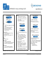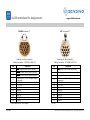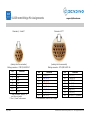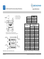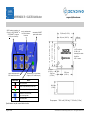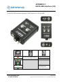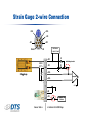
1
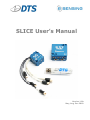
SLICE User’s Manual Version 1.0b May, Aug, Dec 2010 SLICE User’s Manual [email protected] Table of Contents 1. Contacting Technical Support ................................................................................... 4 1.1. DTS Technical Support ...................................................................................... 4 1.2. DTS Web Site .................................................................................................. 4 1.3. DTS Offices ..................................................................................................... 4 2. SLICE Overview...................................................................................................... 6 2.1. SLICE MICRO and SLICE NANO........................................................................... 6 2.2. SLICE Modular Concept ..................................................................................... 6 2.3. SLICE Basic Hardware Components..................................................................... 8 2.3.1. Base SLICE............................................................................................... 8 2.3.2. Bridge SLICE ............................................................................................ 9 2.3.3. IEPE SLICE ............................................................................................... 9 2.3.4. Digital SLICE .......................................................................................... 10 2.3.5. ACCEL SLICE .......................................................................................... 10 2.3.6. ARS SLICE.............................................................................................. 10 2.3.7. Battery SLICE ......................................................................................... 11 2.3.8. Stack Extender ....................................................................................... 11 2.3.9. End-of-Chain (EOC) Terminal .................................................................... 11 2.3.10. SLICE System Interface............................................................................ 12 2.3.11. SLICE Distributor..................................................................................... 13 2.3.12. SLICE USB Interface ................................................................................ 13 2.3.13. SLICE Ethernet Interface .......................................................................... 14 2.3.14. SLICE MICRO and NANO Connectors .......................................................... 15 2.4. Batteries ....................................................................................................... 15 2.4.1. 9.6 V Rechargeable NiMH Batteries ............................................................ 15 2.4.2. 11.1 V Rechargeable Lithium-Polymer Batteries ........................................... 16 2.5. SLICE Software .............................................................................................. 16 3. Mounting and Connecting SLICE Hardware ............................................................... 16 3.1. General Connection Guidelines ......................................................................... 16 3.2. Guidelines for High Shock and Vibration Testing.................................................. 17 3.3. SLICE Connectors and Cables........................................................................... 17 3.3.1. SLICE Connectors .................................................................................... 17 3.3.2. SLICE Cables .......................................................................................... 18 3.4. Power Requirements ....................................................................................... 19 3.5. Using the End-of-Chain (EOC) Terminal ............................................................. 20 3.6. Using the SLICE System Interface..................................................................... 21 3.7. Using the SLICE USB Interface ......................................................................... 22 3.8. Using the SLICE Ethernet Interface ................................................................... 23 3.9. Using the SLICE Distributor.............................................................................. 24 4. Sensor ID and Supported Sensor Types................................................................... 25 4.1. Sensor ID...................................................................................................... 25 4.2. Supported Sensor Types.................................................................................. 26 5. Software ............................................................................................................. 26 5.1. Basic Requirements ........................................................................................ 26 5.2. Data Collection Concepts ................................................................................. 27 5.2.1. Standalone Operation .............................................................................. 27 5.2.2. Data Collection Modes .............................................................................. 27 Version 1.0 - May 2010 2 ©DTS, Inc. - All Rights Reserved SLICE User’s Manual [email protected] 5.2.2.1. Circular Buffer Mode........................................................................... 27 5.2.2.2. Recorder Mode .................................................................................. 27 5.3. SLICEWare .................................................................................................... 27 5.3.1. Software Installation ................................................................................ 28 5.3.2. Menu Descriptions ................................................................................... 29 6. Powering Up SLICE ............................................................................................... 43 6.1. Status (STS) LED ........................................................................................... 43 6.2. Power (PWR) LED ........................................................................................... 44 Appendix A: SLICE Buyer’s Guide ............................................................................... 45 Appendix B: Base and Bridge SLICE Specifications ........................................................ 54 Appendix C: End-of-Chain (EOC) Terminal ................................................................... 60 Appendix D: SLICE System Interface .......................................................................... 61 Appendix E: SLICE Distributor .................................................................................... 64 Appendix F: SLICE USB Interface ............................................................................... 68 Appendix G: SLICE Ethernet Interface ......................................................................... 70 Appendix H: SLICE Grounding Recommendations.......................................................... 72 Appendix I: Bridge SLICE Sensor Connection Guide....................................................... 78 Appendix J: Software Reference ................................................................................. 84 Version 1.0 - May 2010 3 ©DTS, Inc. - All Rights Reserved SLICE User’s Manual [email protected] 1. Contacting Technical Support DTS is a world leader in ultra-small, low power, high shock rated, high sample rate data acquisition and sensing systems. DTS is based in Seal Beach, California, USA, just south of Los Angeles. DTS has offices in 6 times zones for fast, expert technical support. 1.1. DTS Technical Support For the fastest technical support, please contact your local DTS technical support engineer or e-mail [email protected]. 1.2. DTS Web Site For the most up to date specifications, user’s manuals and other information, please go to www.dtsweb.com. 1.3. DTS Offices United States Eastern Standard Time (EST) (GMT-5) Please call DTS North American Technical Center +1 248 427-0045 7:00 AM - 5:00 PM, Monday through Friday After hours, please e-mail [email protected] Pacific Standard Time (PST) (GMT-8) Please call DTS Corporate Headquarters +1 562 493-0158 7:00 AM - 5:00 PM, Monday through Friday After hours, please e-mail [email protected] Japan (GMT+9) Please contact DTS Japan Technical Center Rihito Shoji 9:00 AM - 5:00 PM (Japan), Monday through Friday After hours, please e-mail [email protected] Version 1.0 - May 2010 4 ©DTS, Inc. - All Rights Reserved SLICE User’s Manual [email protected] Europe (GMT+1) Please contact Dave Martin, European Regional Manager +49 17 11 286 033 (German and English language support) 8:00 AM - 5:00 PM (Germany), Monday through Friday After hours, please e-mail [email protected] Asia/Pacific (GMT+11) Please call Steve Mitchell, Asia Pacific Regional Manager +61 438 507 449 8:00 AM - 5:00 PM (Australia), Monday through Friday After hours, please e-mail [email protected] China (GMT+8) Please call Xi Tianlu, Asia Pacific Regional Manager +86 21-6386-7559 8:00 AM - 5:00 PM (China), Monday through Friday After hours, please e-mail [email protected] India (GMT+5.30) Please call Dave Martin, Regional Manager +49 17 11 286 033 8:00 AM - 5:00 PM (Europe), Monday through Friday After hours, please e-mail [email protected] Version 1.0 - May 2010 5 ©DTS, Inc. - All Rights Reserved SLICE User’s Manual [email protected] 2. SLICE Overview For a quick overview of SLICE, please see the SLICE Buyer’s Guide in Appendix A. SLICE is an ultra small, low power, high shock rated data acquisition system. SLICE is a standalone system with microprocessor, memory, sensor excitation and signal conditioning with options for built-in battery and internal sensors. Systems from 3 to hundreds of channels can be built-up in 3 channel increments. 2.1. SLICE MICRO and SLICE NANO SLICE comes in two sizes: ! SLICE MICRO (42 x 42 mm) ! SLICE NANO (26 x 31 mm) They have the exact same function and circuit boards inside. SLICE MICRO has builtin connectors; SLICE NANO has wires with connectors. 31 mm 26 mm SLICE NANO 42 mm 42 mm SLICE MICRO 2.2. SLICE Modular Concept Modular system – Plug multiple SLICEs onto Base SLICE to make a Stack ! Each SLICE “Stack” can accommodate 8 Sensor Input SLICES. Each Bridge SLICE has 3 analog input channels. You may want multiple “Stacks” if more channels are needed or placement in different locations makes sense for your application. ! Each SLICE “Stack” consists of 1 Base SLICE and up to 8 additional Sensor Input SLICEs. Version 1.0 - May 2010 6 ©DTS, Inc. - All Rights Reserved SLICE User’s Manual [email protected] Example SLICE set-up with multiple stacks: ! SLICE stacks are mounted to the device under test and chained together. ! The End-of-Chain Terminal can be connected to a trigger, battery, or other devices. ! The beginning of the chain is connected to the SLICE Interface Device, SLICE Ethernet Interface, SLICE USB Interface or directly to the PC. PC can be disconnected after arming for standalone operation. ! Up to 4 SLICE stacks can be in any one chain. ! SLICE Distributor (not shown) allows for up to 4 SLICE chains for hundreds of channel in one set-up. Many options: • Battery • Trigger input • Monitor status • Up to 4 Stacks PC provides USB control SLICE Interface Device Device Under Test Example: Crash dummy, aircraft wing, vehicle chassis, industrial machinery, bridge structure, etc. Version 1.0 - May 2010 7 ©DTS, Inc. - All Rights Reserved SLICE User’s Manual [email protected] 2.3. SLICE Basic Hardware Components Below are the basic components of a SLICE system. You will have some subset of these depending on your application or what was ordered. The table below provides an overview of the types of SLICE modules available. Some modules are only available in the MICRO or NANO version. SLICE Module Description MICRO NANO Available Base SLICE One needed for each SLICE Stack Yes Yes Now Bridge SLICE 3 channels of piezo-resistive and voltage sensor inputs. Yes Yes Now IEPE SLICE 3 channels of piezo-electric sensor inputs Yes No 4th qtr 2010 Digital SLICE 8 channels of isolated digital inputs Yes Yes 4th qtr 2010 Accel SLICE Bridge SLICE with integrated 3-axis accelerometer Yes No Now ARS SLICE Bridge SLICE with integrated 3-axis Angular Rate Sensor Yes No Now Stack Battery 2 cell LiPo battery connected to bottom of Base SLICE No Yes Now 2.3.1. Base SLICE See Appendix B for detailed specifications. You must have at least one Base SLICE for any SLICE system. The Base SLICE is at the bottom of the SLICE stack and has these components: ! Microprocessor ! 6 GB flash data memory (standard) ! USB hub ! Power conditioning ! Control signals A Base SLICE MICRO is shown below. Connector to Bridge SLICE or other input SLICEs SLICE Bus Up towards PC SLICE Bus Down to next Base SLICE Version 1.0 - May 2010 8 ©DTS, Inc. - All Rights Reserved SLICE User’s Manual 2.3.2. [email protected] Bridge SLICE See Appendix B for detailed specifications. Up to 8 Bridge SLICEs can be stacked on top of the Base SLICE. Each Bridge SLICE has these components: ! 3 channels of analog input ! Sensor excitation ! 16 bit, 100 kHz ADC, one per channel ! Software adjustable gain, anti-alias filters, offset, and shunt check ! TEDS sensor ID A Bridge SLICE MICRO is shown below. Connector to next Bridge SLICE Sensor input channels 2.3.3. IEPE SLICE Available in fourth quarter 2010 in SLICE MICRO size only. Features: ! 3 input channels ! Power: 26 VDC ! Current source: 2-4 mA Version 1.0 - May 2010 9 ©DTS, Inc. - All Rights Reserved SLICE User’s Manual 2.3.4. [email protected] Digital SLICE Available in fourth quarter 2010. Preliminary specifications: ! Supply will have isolated +5 V ! 8 isolated inputs ! Input modes supported: o CCNO - Contact closure normally open o CCNC - Contact closure normally closed o VIHL - Voltage Input High-Low o VILH - Voltage Input Low-High; 3 input channels 2.3.5. ACCEL SLICE The ACCEL SLICE has Bridge SLICE electronics with the addition of a built-in 3axis accelerometer. The following specifications apply: ! MSI Model 3038 accelerometers are used (see www.meas-spec.com) ! Options from 50 to 2000 g ! DC response Accel and ARS SLICEs can be positioned in any order in a SLICE MICRO stack ARS SLICE ACCEL SLICE 2.3.6. ARS SLICE The ARS SLICE has Bridge SLICE electronics with the addition of a built-in 3-axis angular rate sensor. The following specifications apply: ! DTS ARS are used (see http://dtsweb.com/products/esensing_angular.php) ! Options from 300 to 50000 deg/sec ! DC response Version 1.0 - May 2010 10 ©DTS, Inc. - All Rights Reserved SLICE User’s Manual 2.3.7. [email protected] Battery SLICE The Battery SLICE is connected to the bottom of the Base SLICE. It is only available in the SLICE NANO version. The Battery SLICE is only a back-up battery in case main power is lost. Specifications: ! 2 cell LiPo design, with charging directly from Base SLICE ! ~10 second run time ! Only 3.5 mm thick 2.3.8. Stack Extender The Stack Extender is only available for the SLICE NANO package. The Stack Extender allows the user to create a flatter, longer package. Stack Extender ! Example: 12 channel system ! 1 Base SLICE ! 4 Bridge SLICEs 2.3.9. End-of-Chain (EOC) Terminal See Appendix C for detailed specifications. The EOC Terminal provides the easiest method to attach a battery, trigger signal and status lamp to the SLICE system. It is ruggedized for high shock use. Maximum channels: 1 chain x 2 stacks x 8 Bridge SLICEs x 3 chan/Bridge = 48 channels Version 1.0 - May 2010 11 ©DTS, Inc. - All Rights Reserved SLICE User’s Manual [email protected] To DN port on Base SLICE MICRO or NANO Connections: ! 2 SLICE stack chain ! 9 to 15 VDC input power ! ON signal ! Status output, start record input and event input signals 2.3.10. SLICE System Interface See Appendix D for detailed specifications. The SLICE System Interface allows the connection of one SLICE chain. It is ruggedized for high shock use. Maximum channels: 1 chain x 4 stacks x 8 Bridge SLICEs x 3 chan/Bridge = 96 channels Connections: ! 1 SLICE stack chain ! USB communications ! 9 to 20 VDC input power ! ON/OFF switch ! AUX input (battery, trigger, etc.) Version 1.0 - May 2010 12 ©DTS, Inc. - All Rights Reserved SLICE User’s Manual [email protected] 2.3.11. SLICE Distributor See Appendix E for detailed specifications. The SLICE Distributor allows the connection of up to four SLICE chains. It is ruggedized for high shock use. Maximum channels: 4 chains x 4 stacks x 8 Bridge SLICEs x 3 chan/Bridge = 384 channels Connections: ! 4 SLICE stack chains ! Ethernet communications ! 9 to 20 VDC input power ! ON/OFF switch ! AUX input (battery, trigger, etc.) 2.3.12. SLICE USB Interface See Appendix F for detailed specifications. The SLICE USB Interface allows the connection of one SLICE chain. It is meant for bench-top use and is not ruggedized. Maximum channels: 1 chain x 4 stacks x 8 Bridge SLICEs x 3 chan/Bridge = 96 channels Connections: ! 1 SLICE stack chain ! USB communications ! 9 to 15 VDC input power ! ON/OFF switch ! Manual Start/Event ! AUX input (battery, trigger, etc.) Version 1.0 - May 2010 13 ©DTS, Inc. - All Rights Reserved SLICE User’s Manual [email protected] 2.3.13. SLICE Ethernet Interface See Appendix G for detailed specifications. The SLICE Ethernet Interface allows the connection of two SLICE chains. It is meant for bench-top use and is not ruggedized. Maximum channels: 2 chains x 4 stacks x 8 Bridge SLICEs x 3 chan/Bridge = 192 channels Connections: ! 2 SLICE stack chains ! Ethernet communications ! 9 to 15 VDC input power ! ON/OFF switch ! Manual Start/Event ! AUX input (battery, trigger, etc.) Version 1.0 - May 2010 14 ©DTS, Inc. - All Rights Reserved SLICE User’s Manual [email protected] 2.3.14. SLICE MICRO and NANO Connectors See Section 3 for more connector information. SLICE systems use lightweight, rugged plastic connectors with reliable, gold plated contacts. These are a MIL-STD-type pin and socket configuration where the socket is exposed, instead of the pin, which is mechanically more robust. For some bench-top units, LEMO-style as well as industry standard USB, Ethernet and SubD connectors are used. A typical SLICE rugged plastic connector is shown below. Finger actuated retention latch Exposed sockets Recessed pins 2.4. Batteries DTS offers some commercial-off-the-shelf batteries for operation of SLICE systems. Batteries must be disconnected from the SLICE system before connecting to a charger. 2.4.1. 9.6 V Rechargeable NiMH Batteries ! ! Allows up to 40 min runtime with a 6 channel SLICE System. Package of 4 batteries ensures you’ll always have back-ups ready to use. Version 1.0 - May 2010 15 ©DTS, Inc. - All Rights Reserved SLICE User’s Manual 2.4.2. [email protected] 11.1 V Rechargeable Lithium-Polymer Batteries ! Available in 3 capacities: 2200, 4400, and 6600 mAh 2.5. SLICE Software See Section 4.0 for detailed software information. The SLICEWare software application allows for easy: ! Test set-up ! Sensor database management ! Real-time sensor check-out ! Test execution ! Data download and viewing ! Data export A SLICE API (Application Programmers Interface) and LABView driver (fourth quarter 2010) are also available. Please contact technical support ([email protected]) for the latest update to your software version. 3. Mounting and Connecting SLICE Hardware This section gives details on how to connect your SLICE hardware. Choose the connection method you have from the options below for the quickest information. 3.1. General Connection Guidelines Great care should always be taken when connecting any power, switch, sensor or any other device to the SLICE system. ! DO NOT exceed the rated voltage input range for the device. Whenever possible use the power supply or battery pack supplied with your SLICE system. Version 1.0 - May 2010 16 ©DTS, Inc. - All Rights Reserved SLICE User’s Manual [email protected] ! DO NOT connect directly to vehicle power or other noisy power sources. ! ALWAYS disconnect the battery from the SLICE system before connecting to a battery charger. ! ALWAYS use SLICE NANO with a heat sink as the SLICE NANO case is very thin aluminum with very little heat sinking ability. Never use SLICE NANO mounted to a thermally non-conductive surface like wood or plastic. ! Refer to proper grounding procedures described in Appendix H. ! Check that all cables show no signs of physical damage. ! Be sure all sensors have their cable shields ungrounded at the sensor end and grounded at the SLICE input connector. 3.2. Guidelines for High Shock and Vibration Testing SLICE MICRO and SLICE NANO components can generally be used in test environments with maximum acceleration levels as high as 500 g. In some cases, SLICE NANO can be used up to 5,000 g if proper care is used. Proper mounting of the SLICE system, cables, and accessories is critical to successful testing. ! DO NOT mount SLICE components in an area where they may be directly impacted by an object. ! Use damping material whenever possible to help protect the SLICE system from excessive shock or vibration, but remember that SLICE NANO requires a heat sink. ! Be sure that connectors and wiring are properly secured. 3.3. SLICE Connectors and Cables 3.3.1. SLICE Connectors SLICE is an ultra small data acquisition system. One challenge with a small system is electrical connections. Although connectors such as Bendix, Amphenol, and LEMO are common for instrumentation, all of these are much too large to be practical for SLICE. The SLICE system uses circular plastic connectors manufactured by Omnetics Corporation (www.omnetics.com). These connectors use high-quality, machined contacts and are used in many military, aerospace and other high shock applications. Connectors are available direct from Omnetics or can be purchased from DTS. Below are the connector types used by SLICE. Version 1.0 - May 2010 17 ©DTS, Inc. - All Rights Reserved SLICE User’s Manual 3.3.2. [email protected] SLICE Cables DTS provides a number of different SLICE cable options depending on the connection needs. SLICE stack to stack connection cables are shown below. SLICE MICRO Base units can be connected together via a daisy-chain cable. SLICE NANO Base units can be connected to each other directly or via a daisychain extension cable. Version 1.0 - May 2010 18 ©DTS, Inc. - All Rights Reserved SLICE User’s Manual [email protected] 3.4. Power Requirements The SLICE system runs on DC power. To calculate the rough power needs for a particular system, use the information below: POWE R!RE QUIREMENTS! 10!V!POWER! INPUT /5! V!SENSOR!EX CITATION! IDLE! RECORDING! BASE!SLICE! 40!mA! 110!mA! BRIDGE!SLICE! ! 2!mA! 55! mA! SENSOR!LOAD!(350!o hm/5!V!SENS OR!EX CITATION!)! 0!mA! 50!mA! SINGLE!STACK!POWER!C ONSUMPTION !AT!5!!V!SENS OR! EXCITATION!! TOTAL! BASE!(QTY)! 1! BRIDGE!(QTY)! 2! SENSOR!LOAD!(%!of! 350! ohm)! 100! IDLE!C URRENT! ! 44!mA! IDLE!P OWER! ! 330! mW! RECORD!CURRENT! ! 320! mA! RECORD!POWER! ! 2400!mW ! Version 1.0 - May 2010 19 ©DTS, Inc. - All Rights Reserved SLICE User’s Manual [email protected] 3.5. Using the End-of-Chain (EOC) Terminal A diagram showing connections using the EOC Terminal is shown below. Notes: ! Although this shows a SLICE MICRO system, connections with a SLICE NANO are similar. ! The EOC Terminal is a shock rated item. ! Voltage input can be provided via the included power supply, a battery or any voltage source between 9 and 15 VDC. Warning: Do not exceed the 15 VDC input voltage range as damage may result. ! The ON terminal must be connected to the GND on the EOC Terminal for the SLICE unit to turn on. ! If you connect an LED between the STS and GND terminals, you will get a Status light when the system is armed. Version 1.0 - May 2010 20 ©DTS, Inc. - All Rights Reserved SLICE User’s Manual [email protected] To DN port on the last Base SLICE MICRO or NANO in a SLICE chain See Appendix C for detailed information on the SLICE End-of-Chain Terminal. 3.6. Using the SLICE System Interface The SLICE System Interface is similar to the EOC Terminal except it is used between the first/only SLICE Stack and the PC. See the example diagram below. Version 1.0 - May 2010 21 ©DTS, Inc. - All Rights Reserved SLICE User’s Manual [email protected] Notes: ! Although this shows a SLICE MICRO, connections with a SLICE NANO are similar. ! The SLICE System Interface is a shock rated item. ! The AUX Terminal can be used for easy connection to a battery, start record, trigger, and status signal. ! Voltage input through the SLICE System Interface can be provided via the included power supply a battery, or any voltage source between 9 and 20 VDC. Warning: Do not exceed the 20 VDC input voltage range as damage may result. ! The SLICE System Interface has a recessed ON switch. Alternately the ON signal can be connected to the GND on the EOC Terminal. ! If you connect an LED between the STS and GND terminals on the EOC Terminal you will get a Status light when the system is armed. 3.7. Using the SLICE USB Interface The SLICE USB Interface is similar to the SLICE System Interface. The main difference is that the SLICE USB Interface is designed for bench-top, non-rugged use. See the example diagram below. Version 1.0 - May 2010 22 ©DTS, Inc. - All Rights Reserved SLICE User’s Manual [email protected] Notes: ! Although this shows a SLICE MICRO, connections with a SLICE NANO are similar. ! The SLICE USB Interface is NOT a shock rated item. ! Voltage input can be with the included power supply a battery, or any voltage source between 9 and 15 VDC. Warning: Do not exceed the 15 VDC input voltage range as damage may result. ! The AUX connector is a standard D-sub HD15. This can be used to hardwire a Start Record or Event switch or monitor the Status line. 3.8. Using the SLICE Ethernet Interface The SLICE Ethernet Interface is similar to the SLICE USB Interface. The main difference is that the SLICE Ethernet Interface has an Ethernet connection to the PC instead of a USB connection. This allows for a longer communications cable between the PC and the SLICE system. The SLICE Ethernet Interface can also connect 2 SLICE chains for large system configurations. See the example diagram below. Notes: ! Although this shows a SLICE MICRO, connections with a SLICE NANO are similar. Version 1.0 - May 2010 23 ©DTS, Inc. - All Rights Reserved SLICE User’s Manual ! ! ! [email protected] The SLICE Ethernet Interface is NOT a shock rated item. Voltage input can be with the included power supply a battery, or any voltage source between 9 and 15 VDC. Warning: Do not exceed the 15 VDC input voltage range as damage may result. The AUX connector is a standard D-sub HD15. This can be used to hardwire a Start Record or Event switch or monitor the Status line. 3.9. Using the SLICE Distributor The SLICE Distributor allows for the connection of up to 4 SLICE chains and converts the communications signals from USB to Ethernet. This allows for a longer communications cable between the PC and the SLICE system. The most common application for the SLICE Distributor is for an embedded system with a high channel count as shown for the in-dummy (manikin) configuration below. SLICE Application Diagram: 42-channel integrated SLICE NANO for H3-50% Dummy Version 1.0 - May 2010 24 ©DTS, Inc. - All Rights Reserved SLICE User’s Manual [email protected] 4. Sensor ID and Supported Sensor Types This section covers basic information regarding SLICE compatible sensors and sensor ID. More detailed information regarding sensor connections can be found in Appendix I. The diagram below shows a common 4-wire bridge sensor connection to a Bridge SLICE input channel. 4.1. Sensor ID Sensor ID is also referred to as electronic ID (EID). The function of EID is for the SLICE hardware to automatically read and determine what sensor is attached to each sensor input channel. SLICE uses EID chips from Maxim IC, model DS2401 (see http://www.maximic.com/quick_view2.cfm/qv_pk/2903). To make soldering of the EID more easy, DTS provides EID microcards, which have a chip scale packaged DS2401 soldered to a circuit board with wires attached (see below). Version 1.0 - May 2010 25 ©DTS, Inc. - All Rights Reserved SLICE User’s Manual [email protected] EID “microcard” soldered to pins 4 and 6 Omnetics 7-pin Sensor Connector 4.2. Supported Sensor Types The Bridge SLICE supplies 5 VDC excitation up to 20 mA and supports many types of accelerometers, load cells, pressure sensors and other sensor types. The following general sensor types are supported: ! Full (4-wire) or half bridge (2- or 3-wire) resistive and piezo-resistive types ! Voltage input: Input range 0.1 to 4.9 V; larger range with voltage expander circuit ! Conditioned sensors with 5 V excitation and 2.5 V centered signal output The IEPE SLICE MICRO (fourth quarter 2010) will support common piezo-electric sensor types. If you have questions regarding what sensors are supported please contact [email protected] and provide the sensor manufacturer and model number if available. 5. Software This section covers software installation and use. See Appendix J for additional software reference information regarding files formats and firmware updates. 5.1. Basic Requirements SLICEWare is a Windows® based program. Minimum PC specifications are: ! ! ! ! ! Windows XP, Windows Vista, or Windows 7 32-bit. 64-bit support is coming soon 1 GHz or faster processor 2 GByte RAM minimum. More RAM is important for longer/higher sample rate data acquisition. 100 MByte disk space for Software plus storage for test data 1024 x 768 minimum screen resolution Version 1.0 - May 2010 26 ©DTS, Inc. - All Rights Reserved SLICE User’s Manual 5.2. [email protected] Data Collection Concepts This section discusses the basics of data collection with SLICE. 5.2.1. Standalone Operation SLICE is a standalone data logger. This means that once it is armed, the PC can be disconnected if desired. After receiving a Start Record or Trigger signal, the SLICE autonomously collects data, storing it to flash memory with no user interaction. After the test, the user can reconnect the PC to download the data. There is also a real-time mode in the SLICEWare software application that allows the user to check channel inputs on an oscillograph-looking screen. 5.2.2. Data Collection Modes SLICE supports two data collection modes, Circular Buffer and Recorder. 5.2.2.1. Circular Buffer Mode In circular buffer mode, the user can program SLICE to record pre-trigger data. For example, the test set-up can specify to record x seconds pretrigger and x seconds post trigger. Time Zero (T=0) is marked when the trigger signal is received. 5.2.2.2. Recorder Mode Recorder mode starts when a Start Record signal is received and continues for the time specified in the test set-up. If a trigger signal is received sometime after the Start Record, this marks the T=0 point. 5.3. SLICEWare This section discusses the basics of data collection with SLICE using the SLICEWare application. The SLICEWare software application allows for easy: ! Test set-up ! Sensor database management ! Real-time sensor check-out ! Test execution ! Data download and viewing ! Data export Version 1.0 - May 2010 27 ©DTS, Inc. - All Rights Reserved SLICE User’s Manual 5.3.1. [email protected] Software Installation Locate the installation files on the CD or flash drive provided. Double-click the “set-up.exe” file to begin installation. for each of the screens: set-up wizard, driver installation, Click installation folder and confirming installation. Version 1.0 - May 2010 28 ©DTS, Inc. - All Rights Reserved SLICE User’s Manual [email protected] You must allow the driver to be installed. You may see these screens: For Windows® Vista, click to “Install this driver software anyway.” For Windows® XP, click “Continue Anyway.” Note: Windows® will ask you to reinstall the hardware driver each time you connect the SLICE stack to a different USB port. To start SLICEWare, either double-click the 5.3.2. icon or go to: Menu Descriptions Click Prepare tab … This tab identifies the relationship between available sensors and the attached SLICE units. Sensor information can be added, removed, viewed, edited or assigned to channels on connected data acquisition hardware. Version 1.0 - May 2010 29 ©DTS, Inc. - All Rights Reserved SLICE User’s Manual [email protected] The image below highlights the different screen areas. The red boxes and type are used in this manual only (not visible in actual software). RIBBON CONTROL SENSOR LIST SENSOR DETAIL CONNECTED SENSORS STATUS BAR Click anywhere on a line in the Sensor List to show the Sensor Details for that sensor. SENSOR LIST SENSOR DETAIL Version 1.0 - May 2010 30 ©DTS, Inc. - All Rights Reserved SLICE User’s Manual [email protected] Prepare Tab Groupings Current Sensor Manual Sensor Assignment Sensor ID Current Sensor ! Add: Will add a blank Sensor Details field to all for creating a new sensor entry. ! Delete: Deletes the sensor that is highlighted in the sensor list. ! Undo Edit: Reverts all edits made in the sensor details fields. ! Read ID: Reads the EID from the channel selected in the Connected Sensor list. The returned ID value will be populated in the Sensor ID field for the sensor that is highlighted in the sensor list. ! Measure Bridge: Measures a sensors bridge resistance from the channel selected in the Connected Sensor list. The returned bridge resistance will be populated in the Bridge resistance (ohms) field for the sensor that is highlighted in the sensor list. ! Save: Saves edits made in the Sensor Detail area. Manual Sensor Assignment ! For sensors connectors without an EID. ! You cannot un-assign or overwrite an auto-assigned channel. ! Assign: After highlighting a sensor in the Sensor List and highlighting an un-assigned channel in the Connected Sensors area, use this to assign the sensor. ! Un-assign: Remove the highlighted channel in the Connected Sensors area. ! Apply: Commits the sensor set-up information to SLICE. ! Note: A sensor that is manually applied should not have a value in the Sensor ID field and the SLICE should not have an EID installed on the connector. If the Sensor ID field is populated or an EID exists on the channel, the sensor will need to be re-applied after switching away from and then back to the Prepare tab. Version 1.0 - May 2010 31 ©DTS, Inc. - All Rights Reserved SLICE User’s Manual [email protected] Sensor ID ! Refresh: The sensor IDs are read when the software is started or when a SLICE is rebooted. If sensor connections are switched, choosing refresh will read the connected IDs on the current channels. Sensor Details General Calibration History Attributes Options General ! Serial Number: Used to identify the sensor. Can be any unique identifier. The sensor list is sorted by default with the serial number. ! Comment: User field can be any text entry. ! Manufacturer: Not enabled as of 200910. ! Model: Not enabled as of 200910. ! Sensor ID: Enter or “READ ID” to populate. Attributes ! Full Scale: The maximum expected value the sensor will be subjected to. ! Units: The Engineering Units of the sensor. ! Sensitivity: o When Proportional to Excitation is checked: This value is the calibrated sensitivity in mV/V/EU. o When Proportional to Excitation is un-checked: This value is the calibrated sensitivity in mV/EU. ! Initial EU: Typically left at 0.00. This entry may be used to insert an engineering value to the starting point of the recorded sensor. ! Excitation: Leave at 5.0. Adjustment is not enabled as of 200910. Version 1.0 - May 2010 32 ©DTS, Inc. - All Rights Reserved SLICE User’s Manual [email protected] Calibration History ! This field is automatically updated whenever a new sensitivity is applied to the sensor attributes. You cannot enter directly into this field. Options ! Invert: When checked, the data will be inverted. ! Shunt Check and Bridge Resistance: When Shunt Check is checked, the sensor will have the bridge resistance measured during diagnostics and compared to the value entered in Bridge resistance. ! SW Filter: Choose the frequency of a software filter to be applied to the data when viewing. This only affects the viewed data as all data stored will be as collected with the hardware anti-alias filter. ! Zero Method (post download software zeroing): o Use Pre-Cal Zero: The Zero Measured Output (ZMO) of the sensor during calibration will be used to set the EU zero of the downloaded data. o Average Over Time: Used in conjunction with ZeroStart and ZeroEnd, the average EU value during the Start and End window will be used to Zero the collected data. The Zero Start/End window must be set to data that will be collected. If using a negative time, then the Acquire tab must include this window. o None: The actual recorded input will not be adjusted or compensated for zero level. This setting can be used to show the actual mV offset. An example may be to record a logic level signal and see the actual on/off state. o Remove Offset (hardware): When checked, this will remove the ZMO during diagnostics. This will “electrically” zero the input. o ZeroStart/End: See Zero Method!Average Over Time. o Offset Check: Used in conjunction with Limit Low/High during diagnostics. When checked, the ZMO is measured and compared the Low/High limits as a pass/fail criteria during diagnostics. Step-by-Step Procedure to Add a New Sensor 1. On the PREPARE tab, click the “Add” button in the “Current Sensor” button group Version 1.0 - May 2010 33 ©DTS, Inc. - All Rights Reserved SLICE User’s Manual [email protected] 2. Edit the Sensor Details Field 3. Select “Save” in the “Current Sensor” button group Connect SLICE … Connect the USB and power up the SLICE system… Version 1.0 - May 2010 34 ©DTS, Inc. - All Rights Reserved SLICE User’s Manual [email protected] SLICE hardware appears on right hand side … Click Diagnostics tab … This tab ensures that the connected hardware is operating normally. Hardware diagnostics include checks for battery level, excitation voltage, noise and expected offset. Version 1.0 - May 2010 35 ©DTS, Inc. - All Rights Reserved SLICE User’s Manual [email protected] SLICEWare configures any connected channels … Detailed calibration results for all channels … Version 1.0 - May 2010 36 ©DTS, Inc. - All Rights Reserved SLICE User’s Manual [email protected] Click Real-time tab … This tab shows data input to the attached SLICE hardware in real-time. It is a useful tool for establishing confidence in the current hardware configuration prior to data collection. 1 g roll tests … Version 1.0 - May 2010 37 ©DTS, Inc. - All Rights Reserved SLICE User’s Manual [email protected] Real-time with X, Y and Z … Click Acquire tab … This tab configures and controls the data acquisition process. The user enters the test name, description, sample rate, acquisition mode (circular buffer or recorder mode), pre- and post-trigger times and then prepares the system for data acquisition with the arm command. After the test is completed, the user can use the download command to view the data. Version 1.0 - May 2010 38 ©DTS, Inc. - All Rights Reserved SLICE User’s Manual [email protected] Enter sampling rates and pre-post test times etc … System ARMed … Version 1.0 - May 2010 39 ©DTS, Inc. - All Rights Reserved SLICE User’s Manual [email protected] System triggered and acquiring data … Downloading data … Version 1.0 - May 2010 40 ©DTS, Inc. - All Rights Reserved SLICE User’s Manual [email protected] Click Review tab … This tab displays collected data. Previously downloaded tests can be viewed and examined on a per-channel basis. Dynamic “zoom” selection … Version 1.0 - May 2010 41 ©DTS, Inc. - All Rights Reserved SLICE User’s Manual [email protected] Click Data tab … This tab provides export options for collected data. Export options include CSV, ISO and DIAdem formats. Export options for CSV, ISO and DIAdem formats … Version 1.0 - May 2010 42 ©DTS, Inc. - All Rights Reserved SLICE User’s Manual [email protected] 6. Powering Up SLICE This section covers what to expect when powering up a SLICE system and running a test. The LEDs on the Base SLICE indicate the status of the system. 6.1. Status (STS) LED Action Result Power up Communicating with PC Recording Data (Recorder Mode) -or- Armed (Circular Buffer) Armed in Recorder Mode Unit received Event Idle The status LED is red, green or blue. At system power up, the LED cycles from red to green to blue followed immediately by the power LED boot-up sequence. The status LED indicates communication and arm status. ! When the unit is not armed, the status LED will blink green when handling a command from the PC. ! For Recorder Mode o When the unit is first armed, the LED will go solid blue to indicate that it is waiting for the START RECORD signal but not taking data. o When it receives the START RECORD signal, the LED will turn green to indicate that it is actively recording data. o The LED will turn off when data collection has completed. o If an EVENT signal is received while the unit is recording data, the LED will turn red and then turn off when data collection has completed. ! For Circular Buffer Mode o When the unit is armed, the LED will go solid green to indicate that it is collecting data and waiting for the EVENT signal. o When an EVENT signal is received the LED will turn red and then turn off when data collection has completed. Version 1.0 - May 2010 43 ©DTS, Inc. - All Rights Reserved SLICE User’s Manual [email protected] 6.2. Power (PWR) LED Result (not armed) Action Power up Connected to USB power Only Connected to external power – power is OK Connected to external power – power is low The power LED is red, green or blue. ! At power up, the LED cycles from red to green to blue immediately after the status LED has completed its boot-up sequence. ! When USB is connected, the LED will turn blue. ! With OK external power, the LED will turn green. ! With low external power, the LED will turn red. ! These transitions do not happen if the unit is armed. Version 1.0 - May 2010 44 ©DTS, Inc. - All Rights Reserved APPENDIX A ‐ SLICE Buyer's Guide 1. CHOOSE SLICE™ MICRO OR SLICE™ NANO 2. DEFINE SENSOR NEEDS BASE SLICE (1 REQUIRED PER STACK) Microprocessor 8 G on‐board FLASH memory; 6G for data storage Status controls Connection to PC and additional stacks Available in MICRO and NANO MIX AND MATCH SELECT ANY COMBINATION UP TO 24 CHANNELS PER STACK BRIDGE SLICE (3 channels) SLICE MICRO 3 channel SLICES to create system STACK Connectors built into case enclosure For use with your sensors: ‐ Strain gage ‐ Wheatstone bridge ‐ Voltage based ‐ MEMS piezo‐resistive Available in MICRO and NANO 42 x 42 mm footprint Rugged enclosure perfect for high stress environment ARS SLICE (3 channels) SLICEs available with embedded sensors Internal 3‐axis angular rate sensor Identical electronics as SLICE NANO Ranges from 300 to 50k deg/sec Available in MICRO ONLY SLICE NANO 3 channel SLICEs to create system STACK Connectors via factory installed cable Internal 3‐axis accelerometer 26 x 31 mm footprint Ranges from 50 to 2000 g Recommended for embedded applications Available in MICRO ONLY REV: 3 MAY 2010 ACCEL SLICE (3 channels) SLICE Buyer's Guide 3. DETERMINE NUMBER OF CHANNELS NEEDED Each SLICE STACK consists of 1 BASE SLICE and up to 8 individual 3 channel SENSOR INPUT SLICEs; maximum of 24 channels per STACK; up to 384 chan‐ nels per system 4. CONNECT MULTIPLE SLICE™ STACKS S‐C‐MDC: SLICE MICRO CHAIN CABLE 12‐pin to 12‐pin locking connector Data, power, and control signals SLICE STACKS can be daisy‐chained for larger channel systems or for place‐ ment at different locations BRIDGE SLICE NANO Module ‐Up to 8 per STACK ‐Maximum 24 ch per STACK S‐C‐NDC: SLICE NANO CHAIN CABLE BASE SLICE NANO Module 1 per STACK 12‐pin to 12‐socket locking connector Data, power, and control signals For connections longer than 8 inches BRIDGE SLICE MICRO Module ‐Up to 8 per STACK ‐Maximum 24 ch per STACK BASE SLICE MICRO Module Connections less than 8 inches 1 per STACK REV: 3 MAY 2010 Connections longer than 8 inches SLICE Buyer's Guide 5. SLICE CONNECTION OPTIONS 6. BATTERY OPTIONS SLICE NANO STACK BATTERY S‐EOC: SLICE END OF CHAIN USB Communication 7 to 15 VDC power input Supports up to 4 STACKS in daisy‐chained configuration S‐SSI: SLICE SYSTEM INTERFACE USB Communication 9 to 20 VDC power input Supports up to 4 STACKS in daisy‐chained configuration Recommended for multi‐stack configura‐ tions Charges whenever input power is connected to NANO BASE ~15 min from complete discharge to full charge (10.5 VDC, 100 mA, at input connector on NANO BASE RECHARGEABLE 9.6 V NiMH BATTERIES Allows up to 40 min runtime with 6 channel SLICE System Package of 4 batteries ensures you’ll always have back‐ups ready to use RECHARGEABLE 11.1 VDC LiPo BATTERIES Available in 3 capacities: ‐ 2200 mAh ‐ 4400 mAh ‐ 6600 mAh S‐DB: SLICE DISTRIBUTOR 10 V POWER INPUT/5 V SENSOR EXCITATION IDLE RECORDING BASE SLICE 40 mA 110 mA BRIDGE SLICE 2 mA 55 mA SENSOR LOAD (350 ohm/5 V SENSOR EXCITATION ) 0 mA 50 mA SINGLE STACK POWER CONSUMPTION AT 5 V SENSOR EXCITATION TOTAL Ethernet communication BASE (QTY) 1 9 to 20 VDC power input BRIDGE (QTY) 2 Supports up to 16 STACKS in 4 daisy‐ chained configuration SENSOR LOAD (% of 350 ohm) 100 Recommended for large configurations IDLE CURRENT 44 mA IDLE POWER 330 mW RECORD CURRENT 320 mA RECORD POWER 2400 mW REV: 3 MAY 2010 POWER REQUIREMENTS SLICE Buyer's Guide CABLE KIT OPTIONS: BASE CABLE KIT SLICEWare SOFTWARE SM‐K‐BASE and SN‐K‐BASE CABLE KIT includes: Qty 1. End‐of‐Chain Terminal Qty 1. Power supply and cable Qty 1. USB cable Qty 1. Event/trigger cable TEST ARTICLE CONNECTIONS FOR: ‐ ON SIGNAL ‐ 7‐15 VDC POWER INPUT ‐ STATUS ‐ START RECORD ‐ EVENT/TRIGGER S‐C‐MSC: USB CABLE START/RECORD BUTTON 9 V, 3.3 A POWER SUPPLY S‐EOC: END‐OF‐CHAIN TERMINAL REV: 3 MAY 2010 SLICE Buyer's Guide CABLE KIT OPTIONS: SSI CABLE KIT SLICEWare SOFTWARE SM‐K‐SSI and SN‐K‐SSI CABLE KIT includes: Qty 1. System Interface Qty 1. SSI Aux Terminal Qty 1. Power supply and cable Qty 1. USB cable Qty 1. Event/trigger cable TEST ARTICLE USB CABLE 15 V, 4 A POWER SUPPLY SSI AUX TERMINAL S‐C‐MDC CABLE REV: 3 MAY 2010 CONNECTIONS FOR: ‐ ON SIGNAL ‐ 9‐20 VDC POWER INPUT ‐ STATUS ‐ START RECORD ‐ EVENT/TRIGGER SLICE TECHNICAL SPECIFICATIONS BASE SLICE MICRO BASE SLICE NANO POWER ‐ 7‐15 VDC input voltage to entire stack via BASE ‐ 100 mA maximum current draw ‐ Reverse current protection ‐ Remote power control input for turn‐ ing unit on/off BRIDGE SLICE MICRO BRIDGE SLICE NANO REV: 3 MAY 2010 ‐ 2.5 or 5.0 V excitation via one 20 mA cur‐ rent limited source per channel *voltage set at factory ‐ ±2.4 V input range (2.5 V center) ‐ DC to 40 kHz bandwidth ‐ 1.0 to 1280 gain COMMUNICATION ‐ USB from BASE (Stack) to PC and module to module ‐ Auto offset range = 100% of effective input ‐ 16‐bit SAR, one ADC per channel ‐ DTS software using Windows XP, Vista TRIGGER ‐ Contact closure ‐ Software adjustable, 5‐pole Butterworth, low‐pass, anti‐alias filter (1 Hz—40 kHz) DATA STORAGE ‐ 6 Gbyte non‐volatile flash ‐ 1/2 bridge and shunt emulation support ‐ 120K samples/sec/channel maximum ‐ 120K samples/sec/channel maximum ‐ Recorder or circular buffer mode ENVIRONMENT ‐ 0° to 50° C operating temp ‐ 120 mA maximum current draw (depends significantly on sensor load ‐ Rated to 500g, 4 msec half‐sine SYSTEM ‐ One BASE supports a maximum cur‐ rent draw of 1 A total per stack ‐ Sensor excitation shuts down when not recording THREE INTERNAL SEN‐ SORS (MICRO ONLY) ‐ 3‐axis accelerometers ‐ Exceeds SAEJ211 response ‐ Available range; 50, 100, 200, 2000 g ‐ 65 mA maximum current draw THREE INTERNAL SEN‐ ‐ 3‐axis angular rate sensors ‐ Available ranges; 300, 1500, 8k, 50k deg/sec ‐ 75 mA maximum current draw ACCEL SLICE BACKUP BATTERY ‐ Charges whenever sufficient input STACK BATTERY THREE DIFFERENTIAL, PROGRAMMABLE SEN‐ SOR CHANNELS ‐ ~15 minutes from complete discharge to full charge (10.5 VDC, 100 mA, at input connector on BASE) ‐ Discharge rates: ~16 seconds at 1 A ~ 2 minutes at 400 mA ARS SLICE SLICE TECHNICAL SPECIFICATIONS SLICE™ MICRO and SLICE™ NANO S‐MCS‐07 SENSOR CONNECTOR (DAS SIDE) S‐MCS‐12: CHAIN CONNECTOR S‐MCP‐07‐ID SENSOR CONNECTOR (SENSOR SIDE) S‐MCP‐12: CHAIN CONNECTOR SLICE™ NANO S‐MCS‐16 S‐MCP‐16‐ID SENSOR CONNECTOR (SN‐BR‐3) SENSOR CONNECTOR (SENSOR SIDE) REV: 3 MAY 2010 SLICE MICRO DIMENSIONAL SPECIFICATIONS REV: 3 MAY 2010 SLICE NANO DIMENSIONAL SPECIFICATIONS REV: 3 MAY 2010 APPENDIX B - Base and Bridge SLICE SLICE MICRO Base SLICE NANO Base Power: - 7-15 VDC input voltage to entire stack via Base - 100 mA maximum current draw - Reverse current protection - Remote power control input for turning unit on/off Communication: - USB from Base (Stack) to PC and module to module - DTS software using Windows® XP, Vista Trigger: - Contact closure Data Storage: - 6 Gbyte non-volatile flash - 120k samples/sec/channel maximum - Recorder or circular buffer mode Environment: - 0 to 50°C operating temperature - Rated to 500 g, 4 msec half-sine Specifications may be revised without notice. April 2010 [email protected] System: - One Base supports a maximum current draw of 1 A total per stack - Sensor excitation shuts down when not recording - Exceeds SAEJ211 response SLICE SLICE MICRO NANO SLICE MICRO Accel - 3 internal accelerometers - Options from 50 to 2000 g - 65 mA maximum current draw Bridge SLICE Bridge Three differential, programmable sensor channels: - 2.5 or 5.0 V excitation via one 20 mA current-limited source per channel (voltage set at factory) - ±2.4 V input range (2.5 V center) - DC to 40 kHz bandwidth - 1.0 to 1280 gain - Auto offset range = 100% of effective input - 16-bit SAR, one ADC per channel - Software-adjustable, 5-pole Butterworth, low-pass, anti-alias filter (1 Hz – 40 kHz) - ½ bridge and shunt emulation support - 120 mA maximum current draw (depends significantly on sensor load) MICRO ARS - 3 internal angular rate sensors - Options from 300 deg/sec to 50000 deg/sec - 75 mA maximum current draw SLICE NANO Stack Battery - Charges whenever input power is connected to the Base - ~15 minutes from complete discharge to full charge (10.5 VDC, 100 mA, at input connector on Base) - Discharge rates: ~16 seconds at 1 A ~2 minutes at 400 mA Drawings not to scale. ©Diversified Technical Systems, Inc. - All Rights Reserved SLICE NANO Base Pin Assignments [email protected] DOWN connector** 3 7 10 12 1 1 4 8 4 11 8 11 3 7 10 12 (looking into the connector) (looking into the connector) Mating connector: DTS P/N S-MCP-12 Mating connector: DTS P/N S-MCS-12 Pin Function Pin Function 1 On (contact closure input to ground) 1 On (contact closure input to ground) 2 Start (contact closure input to ground) 2 Start (contact closure input to ground) Event (contact closure input to ground) Status output (5 V via 10K with respect to ground) 7–15 VDC 7–15 VDC Ground Ground USB_PWR USB_DP USB_DM Ground 3 Event (contact closure input to ground) Status output (5 V via 10K with respect to ground) 7–15 VDC 7–15 VDC Ground Ground USB_PWR USB_DP USB_DM Ground 3 4 5 6 7 8 9 10 11 12 ** Both cables are 10 cm in length July 2009 UP* connector** 4 5 6 7 8 9 10 11 12 * to PC ©Diversified Technical Systems, Inc. - All Rights Reserved SLICE NANO Bridge Pin Assignments [email protected] Channels 1-3*** Channels 1, 2 and 3* 1 4 9 1 2 16 6 7 10 13 3 5 5 14 (looking into the connector) (looking into the connector) Mating connector: DTS P/N S-MCP-07 Mating connector: DTS P/N S-MCP-16 Pin 1 2 3 4 5** 6** 7** Function + Sig - Sig + Ex + ID - Ex - ID Shield * Three connectors; cables 6, 10 and 14 cm in length ** Pins 5, 6 and 7 are common July 2009 Pin 1 2 3 4 5 6 7 8 Pin Function 9 10 11 12 13 14 15 16 + Sig (Ch 1) + ID (Ch 1) - Sig (Ch 2) + Sig (Ch 2) - Sig (Ch 1) + Ex (Ch 1) - Ex (Ch 1) + Ex (Ch 2) Function + ID (Ch 2) + Sig (Ch 3) + Ex (Ch 3) - Ex (Ch 3) - Ex (Ch 2) - Sig (Ch 3) + ID (Ch 3) - ID (Ch 1, 2, 3)/Shield *** One connector; cable 10 cm in length ©Diversified Technical Systems, Inc. - All Rights Reserved SLICE NANO Mechanical Specifications 90° cable clearance B C A = 26 mm (1.024 in) B = 20.75 mm (0.817 in) C = 2.62 mm (0.103 in) D = 31 mm (1.220 in) Cables C A Ø3.2 mm (0.125 in) mounting thru holes x2 Accepts M2.5 (loose fit); 4-40 (free fit); M3 (tight fit) 5.5 mm (0.217 in) 4.0 mm (0.157 in) Specifications may be revised without notice. June 2009 Weight Lid Bridge (1 conn) Bridge (3 conn) Base Battery Total Stack Height mm (inch) D B [email protected] 1.5 mm (0.059 in) 6.5 mm (0.256 in) 13.5 (0.531) 17.5 (0.689) 19 (0.748) 23 (0.906) 24.5 (0.965) 28.5 (1.122) 30 (1.181) 34 (1.339) 35.5 (1.398) 39.5 (1.555) 41 (1.614) 45 (1.772) 46.5 (1.831) 50.5 (1.988) 52 (2.047) 56 (2.205) 57.5 (2.264) 61.5 (2.421) 63 (2.480) 67 (2.638) ~2.6 ~12.6 ~13.8 ~14.2 ~7 grams grams grams grams grams Mounting Screw Length (min) BH or SHC M2.5*/M3** 18 22 25 30 30 35 35 40 40 45 45 50 60 60 60 60 70 70 70 70 mm mm mm mm mm mm mm mm mm mm mm mm mm mm mm mm mm mm mm mm 4-40** 3/4" 7/8" 1" 1-1/8" 1-1/8" 1-1/4" 1-3/8" 1-1/2" 1-3/4" 1-3/4" 1-3/4" 2" 2" 2-1/2" 2-1/2" 2-1/2" 2-1/2" 3" 3" 3" Torque specs: * 3.9 in-lb (0.44 Nm); ** 5.2 in-lb (0.59 Nm) ©Diversified Technical Systems, Inc. - All Rights Reserved SLICE MICRO Pin Assignments DOWN and UP* connectors for SLICE 3 1 7 10 12 4 8 11 MICRO Base [email protected] Channels 1, 2 and 3 for SLICE 2 Bridge 1 3 5 7 MICRO 6 (looking into the connector) (looking into the connector) Mating connector: DTS P/N S-MCP-12 Mating connector: DTS P/N S-MCP-07 Pin Function 1 On (contact closure input to ground) 2 Start (contact closure input to ground) 3 Event (contact closure input to ground) Status output (5 V via 10K with respect to ground) 7–15 VDC 7–15 VDC Ground Ground USB_PWR USB_DP USB_DM Ground 4 5 6 7 8 9 10 11 12 Pin 1 2 3 4 5* 6* 7* * Pins 5, 6 Function + Sig - Sig + Ex + ID - Ex - ID Shield and 7 are common * to PC July 2009 ©Diversified Technical Systems, Inc. - All Rights Reserved SLICE MICRO Mechanical Specifications A = 42 mm (1.654 in) B = 34.2 mm (1.346 in) C = 3.9 mm (0.154 in) A B C C B A Ø4.3 mm (0.169 in) mounting thru holes x2 Accepts 6-32 (loose fit); M4 (free fit); 8-32 (tight fit) Weight Lid Accel ARS Bridge Base ~9 ~33 ~33 ~25 ~28 grams grams grams grams grams Height mm (inch) 2 9 9 7 8 Specifications may be revised without notice. April 2010 (0.079) (0.354) (0.354) (0.276) (0.314) Total Stack Height mm (inch) 17 24 26 31 33 35 38 40 42 45 47 49 52 54 56 59 61 63 66 68 70 73 75 77 80 82 84 (0.67) (0.95) (1.02) (1.22) (1.30) (1.38) (1.50) (1.57) (1.65) (1.77) (1.85) (1.93) (2.05) (2.13) (2.21) (2.32) (2.40) (2.48) (2.60) (2.68) (2.76) (2.87) (2.95) (3.03) (3.15) (3.23) (3.31) [email protected] Assembly Screw Length (FH) M3* 16 20 25 30 30 35 35 40 40 45 45 45 50 50 55 55 60 60 65 65 70 70 75 75 80 80 80 mm mm mm mm mm mm mm mm mm mm mm mm mm mm mm mm mm mm mm mm mm mm mm mm mm mm mm Mounting Screw Length (min) (BH or SHC) M4** 22 30 35 35 40 40 45 45 50 50 55 55 60 60 70 70 70 70 70 80 80 80 80 90 90 90 90 mm mm mm mm mm mm mm mm mm mm mm mm mm mm mm mm mm mm mm mm mm mm mm mm mm mm mm 6-32***/8-32** 7/8" 1-1/4" 1-1/4" 1-1/2" 1-1/2" 1-5/8" 1-3/4" 1-3/4" 2" 2" 2-1/4" 2-1/4" 2-1/4" 2-1/2" 2-1/2" 2-1/2" 3" 3" 3" 3" 3" 3" 3-1/2” 3-1/2” 3-1/2” 3-1/2” 3-1/2” Torque specs: * 5.2 in-lb (0.59 Nm); ** 19.8 in-lb (2.24 Nm); *** 9.6 in-lb (1.1 Nm) ©Diversified Technical Systems, Inc. - All Rights Reserved APPENDIX C – SLICE End-of-Chain Terminal [email protected] SLICE End-of-Chain Terminal Function 26 mm (1.024 in) ON Turns on SLICE Connections Contact closure = ON to GND (continuous) If ON signal is removed and the system is not armed, the system will turn off 20.75 mm (0.817 in) 26 mm (1.024 in) If ON signal is removed and the system is armed, the system will remain on and collect data (sufficient input power permitting) V+ Power input STS Status output +V = input voltage (red) -V = GND (black) 5 V logic-level output = STS to GND Conditioned status output; LED direct drive (>20 mA) LED is on only when SLICE is collecting data 20.75 mm (0.817 in) EVNT Event input Contact closure = EVNT to GND (momentary) An EVNT signal can initiate data collection (circular buffer mode) or mark an event within the data collection window (recorder mode) STRT to DN port on SLICE MICRO or SLICE NANO Base Start record input Contact closure = STRT to GND (momentary) A STRT signal initiates data collection (recorder mode) Weight: 12 grams (without cabling) 20-30 AWG terminals. All GND terminations are common. Reverse polarity and overvoltage protection. ©Diversified Technical Systems, Inc. - All Rights Reserved APPENDIX D - SLICE System Interface [email protected] momentary ON/OFF push button switch 42 mm (1.654 in) ! 4,2 mm diam (0.165 in) x2 mounting thru holes Use M4* or 6-32** screws 38,1 mm (1.5 in) see pin assignments for AUX functions 3,9 mm (0.154 in) USB 2.0 3,9 mm (0.154 in) 34,2 mm (1.346 in) 3.5 mm/1.0 mm DC power jack; 10-15 VDC, 4 A max input 38,1 mm (1.5 in) 42 mm (1.654 in) to UP port on SLICE MICRO® or SLICE NANO®; supports <4 A via VDC power or 500 mA via USB power 34,2 mm (1.346 in) 11 mm (0.433 in) Status LED Action No input power Power input detected; system OFF Power input detected; system ON Collecting data Torque specs: * 19.8 in-lb (2.24 Nm); ** 9.6 in-lb (1.1 Nm) Specifications may be revised without notice. August 2009 ©Diversified Technical Systems, Inc. - All Rights Reserved SLICE Interface Pin Assignments [email protected] AUX connector 4 1 9 5 13 16 10 14 (looking into the connector) Mating connector: DTS P/N 13000-30160 Pin 1 2 3 4 5 6 7 8 December 2010 Function ON; contact closure input to ground START; contact closure input to ground EVENT; contact closure input to ground STATUS LED output; 4-5 V, 10 mA max, relative to ground CHARGE output; 10-18 VDC, 2 A out Ground No connection Ground Pin Function 9 10 11 12 13 14 15 16 START input; 1.5-14 VDC, relative to ground +EPWR input; 10-18 VDC, 4 A* Ground Ground EVENT input; 1.5-14 VDC, relative to ground +EPWR input; 10-18 VDC, 4 A* +BAT input; 10-18 VDC, 4 A +BAT input; 10-18 VDC, 4 A * !13 V required for charging SLICE chain/stack battery ©Diversified Technical Systems, Inc. - All Rights Reserved SLICE Interface Pin Assignments (cont.) [email protected] SLICE connector 3 1 7 10 12 4 8 11 (looking into the connector) Mating connector: DTS P/N 13000-30170 Pin Function 1 On (contact closure input to ground) 2 Start (contact closure input to ground) 3 Event (contact closure input to ground) Status output (5 V via 10K with respect to ground) 7–15 VDC 7–15 VDC Ground Ground USB_PWR USB_DP USB_DM Ground 4 5 6 7 8 9 10 11 12 December 2010 ©Diversified Technical Systems, Inc. - All Rights Reserved APPENDIX E - SLICE Distributor SLICE system connectors; to UP port on SLICE MICRO® or SLICE NANO® (supports <10 A per connector) see pin assignments for AUX connector functions [email protected] momentary ON/OFF push button switch 53,98 mm (2.125 in) 49,4 mm (1.945 in) Status LED 43,99 mm (1.732 in) Optional 802.11 b/g wireless support (10-32 antenna port) 48,98 mm (1.929 in) 53,98 mm (2.125 in) see pin assignments for SYS connector functions 4,19 mm (0.165 in) 13,46 mm (0.530 in) 4,99 mm (0.197 in) ! 4,27 mm diam (0.168 in) x2 mounting thru holes Use M4* or 6-32** screws 35,94 mm (1.415 in) Action No input power Power input detected; system OFF 24,89 mm (0.98 in) Power input detected; system ON Armed in recorder mode; not collecting data Collecting data Torque specs: * 19.8 in-lb (2.24 Nm); ** 9.6 in-lb (1.1 Nm) Specifications may be revised without notice. August 2009 ©Diversified Technical Systems, Inc. - All Rights Reserved SLICE Distributor Pin Assignments [email protected] AUX connector 4 1 9 5 13 16 10 14 (looking into the connector) Mating connector: DTS P/N S-MCP-16-SDA Pin 1 2 3 4 5 6 7 8 Function /PWR_ON - Event + Event RECORD_STATUS CHARGE (2 A max) Ground Ground +ID Pin 9 10 11 12 13 14 15 16 Function START_RECORD + BAT Ground No connection CHARGE_STATUS + BAT EN_BAT_PWR Start (contact closure input to ground) 9-20 VDC in; 10 A max December 2009 ©Diversified Technical Systems, Inc. - All Rights Reserved SLICE Distributor Pin Assignments (cont.) [email protected] SYS connector 4 1 9 5 13 16 10 14 (looking into the connector) Mating connector: DTS P/N S-MCP-16-SDX Pin 1 2 3 4 5 6 7 8 December 2009 Function /PWR_ON - Event + Event RECORD_STATUS ON_STATUS Ground Ground No connection Pin 9 10 11 12 13 14 15 16 Function START_RECORD + V1 Ground Tx+ Rx+ + V1 TxRx- ©Diversified Technical Systems, Inc. - All Rights Reserved SLICE Distributor Pin Assignments (cont.) [email protected] SLICE system connectors (1, 2, 3 and 4) 3 1 7 10 12 4 8 11 (looking into the connector) Mating connector: DTS P/N S-MCP-12 Pin Function 1 On (contact closure input to ground) 2 Start (contact closure input to ground) 3 Event (contact closure input to ground) Status output (5 V via 10K with respect to ground) 7–15 VDC 7–15 VDC Ground Ground USB_PWR USB_DP USB_DM Ground 4 5 6 7 8 9 10 11 12 December 2009 ©Diversified Technical Systems, Inc. - All Rights Reserved APPENDIX F SLICE USB Interface (UI) The SLICE USB Interface connects 1 SLICE system to a PC via USB. * * Correct input power applied SLICE system is on SLICE system is recording data * You must pull out on the switch before moving—do not force. [email protected] +1 562 493 0158 March 2010 ©Diversified Technical Systems, Inc. - All Rights Reserved SLICE USB Interface (UI) SLICE (ECG.2B.312.CLL) 8 1 2 3 AUX DB15F (high density) 9 12 10 11 4 7 6 5 (panel view) Pin 1 6 11 5 10 15 Function (panel view) Pin Function 1 /ON 1 /START, CC to ground 2 /START 2 +Status out 3 /EVENT 3 /EVENT, CC to ground 4 STATUS 6 Ground 5 12.6 VDC out 7 -Status out 6 12.6 VDC out 8 Ground 7 Ground 8 Ground 9 USB power 10 USB_DP 11 USB_DM 12 Ground This is a standard USB (“B”) interface. A commercial, off-the-shelf USB cable is acceptable. 15V IN (ECG.2B.304.CLL) 4 2 3 (panel view) Pin Function 1 +Power (15 VDC) 2 -Power/Ground 3, 4 [email protected] +1 562 493 0158 1 Ground March 2010 ©Diversified Technical Systems, Inc. - All Rights Reserved APPENDIX G SLICE Ethernet Interface (EI) The SLICE Ethernet Interface connects 1 or 2 SLICE systems to a PC via Ethernet. * * Input power is over voltage Correct input power applied System boot-up System on All SLICE systems are recording data * You must pull out on the switch before moving—do not force. [email protected] +1 562 493 0158 March 2010 ©Diversified Technical Systems, Inc. - All Rights Reserved SLICE Ethernet Interface (EI) SLICE 1 / SLICE 2 (ECG.2B.312.CLL) 8 1 2 3 AUX DB15F (high density) 9 12 10 11 4 7 6 5 (panel view) Pin 1 6 11 5 10 15 Function (panel view) Pin Function 1 /ON 1 /START, CC to ground 2 /START 2 +Status out 3 /EVENT 3 /EVENT, CC to ground 4 STATUS 6 Ground 5 6.5-15 VDC out 7 -Status out 6 6.5-15 VDC out 8 Ground 7 Ground 8 Ground 9 USB power 10 USB_DP 11 USB_DM 12 Ground This is a standard Ethernet (RJ45) interface. A commercial, off-theshelf patch cable is acceptable. 15V IN (ECG.2B.304.CLL) 4 2 3 (panel view) Pin Function 1 +Power (9-15 VDC range) 2 -Power/Ground 3, 4 [email protected] +1 562 493 0158 1 Ground March 2010 ©Diversified Technical Systems, Inc. - All Rights Reserved APPENDIX H SLICE Grounding Recommendations SLICE Grounding and Shielding Overview Electromagnetic Interference (EMI), Radio Frequency Interference (RFI) and Electrostatic Discharge (ESD) can seriously degrade the performance of electronic equipment if not addressed. DTS SLICE systems contain protection f EMI/RFI/ESD for EMI/RFI/ESD, h however, many d dynamic i ttesting ti environments i t (pyrotechnics, blast) are particularly noisy and require the utmost attention to grounding and shielding practices. The following recommendations are intended to maximize protection and keep systems functioning properly in the harshest environments environments. Ground all DAS equipment, power supplies and sensor mounting fixtures whenever possible. This is an extremely important step toward ensuring the best performance from your SLICE system. • Always connect a cable from a good Earth ground to the test article, test fixture or instrumented vehicle. Not only does this help divert potentially disruptive electrical energy, it is also good safety practice. For remote testing applications, a metal ground rod driven 3 ft into the soil can be an effective Earthing device. • Ground G o nd all SLICE enclos enclosures es to the test a article ticle o or vehicle ehicle • • Install ground cables between all SLICE Stacks and the test article or vehicle. Install ground cables between electrically isolated test article/sensor mounting surfaces and the SLICE Stacks. © 2009-2010 DTS Principles of Dynamic Data Acquisition SLICE Grounding and Shielding Overview Shield sensor cables • • • Use shielded sensor cables. The shield provides a path for EMI/RFI energy to flow to the DAS ground and enclosure, thus reducing effects on sensor signals. Connect the sensor cable shield on the DAS side only to the “Shield” Shield or ground pin on the SLICE. Do not connect the shield at both ends. Connecting the sensor cable shield at both ends will cause large ground-loop currents that can increase noise or cause damage. • PC Grounding? g • • • This is more important than you might think. If the Laptop used to communicate with SLICE is powered from a source that has a significantly different ground potential than the SLICE system, communication with the SLICE can be impaired. In severe cases damage to the laptop or SLICE can occur. Either run the laptop p p on batteryy power p or use a voltmeter to make sure the AC outlet ground is not at a significantly different potential than the ground connected to the test article or vehicle. • Carefully consider routing and cable design for any high current signals to air bags, cameras, lights, etc. • • Route these cables away from sensor wiring wiring. Cross sensor wiring at 90" angles if the cables must cross. © 2009-2010 DTS Principles of Dynamic Data Acquisition Recommended Grounding Architecture Vehicle Body or Test Article Shield NOT connected here Sensor Cable Sensor Isolated metal structure such as a dummy component DAS Mounting Plate SLICE Stack Ground Cable Ground Cable to “Earth” Earth © 2009-2010 DTS Principles of Dynamic Data Acquisition Cable Installation Recommendations • Flat braided ground cable has lower impedance than typical round wires and hence makes a better ground connection. • Never assume that connections are good until you check them with an ohmmeter. Should be <1# for short runs or <5# for long runs. • Ground cables inside test dummies should be braided type with a 12gage equivalent size. • Ground cables from a test article or vehicle to the SLICE Stack should be braided strap type with a 15-gage equivalent size. • The cable from a test article or vehicle to the Earth connection should be large enough to create an a low impedance connection given the distance between Earth connection and test vehicle. 8 to 12 g gage g equivalent q is common. • If braided cable is not available, any ground wire is better than none! © 2009-2010 DTS Principles of Dynamic Data Acquisition Braided Cable • Alpha wire company makes suitable flat braided ground cable in 100 ft lengths. Similar cables from other companies are OK. • Alpha part number: 1230 SV005 • • 3/16 wide, 3/16” wide 15 15-gage gage equivalent Good for SLICE Stack grounding • Available from www.Digi-key.com: part # A1230SV-100-ND • Alpha part number: 1232 SV005 • • 3/8” wide, 12-gage equivalent Good for test article grounding • Available from www.Digi-key.com: part # A1232SV-100-ND © 2009-2010 DTS Principles of Dynamic Data Acquisition APPENDIX I SLICE Bridge Sensor Connection Guide SLICE Bridge – Sensor Interface Excitation Source • One per channel • 5-volts standard • 20 mA continuous • Short circuit safe • ESD Protected Excitation Check Circuit Basic Analog Features 1) 0-5 volt Input Rage 2) Gains of 1 to 1,280 3) True Bridge Completion Shunt Check Circuit +ex +sig -ex -sig Protection and Bridge Co ompletion Sensor 4) 60KHz Bandwidth (max) 5) ESD and d RFI P Protection t ti Differential Instrumentation Amplifier Gain 1-128 2.5V + ID Electronic ID Interface DAC used to null offset. Must zero to <2% A/D f/s. 9-poles of Butterworth filtering Multi-function Summing Amp (Gain 1 or 10) 2-pole 50 KHz Filter 5-pole 1Hz to 45 KHz Adjustable Filter 2-pole 50 KHz Filter 16-bit ADC Standard 4-wire Bridge Connection +SIG -SIG + ID +EX -EX Shield Excitation 5-volts 20 mA -ID 3 +ex -sig 5 Sensor +sig Bridge 1 2 -ex ex 7 6 4 Sensor Side " +EX 3K Half-Bridge Switch $EX 3K +SIG Amplifier $SIG Shield 2.5V $ID + ID Electronic ID Interface ! Internal to SLICE Bridge Strain Gage 3-wire Connection +SIG -SIG + ID +EX -EX Shield Excitation 5-volts 20 mA -ID 3 350# 0.1% 5 1 350# Gage 2 +EX 3K Half-Bridge Switch $EX 3K +SIG Amplifier $SIG 2.5V 7 6 4 Sensor Side " $ID + ID Electronic ID Interface ! Internal to SLICE Bridge Strain Gage 2-wire Connection +SIG -SIG + ID +EX -EX Shield Excitation 5-volts 20 mA -ID 350# 0.1% 3 5 1 350# Gage 2 +EX 3K Half-Bridge Switch $EX 3K +SIG Amplifier $SIG 2.5V 7 6 4 Sensor Side " $ID + ID Electronic ID Interface ! Internal to SLICE Bridge Measuring Large Voltages - Example Lemo Plug (5V) +EX 1 10K + + SIG 10K Amplifier _ - SIG Approx MAX External Voltage Vmax (0V) - EX External Voltage 10K 4 10K SLICE Bridge R 3 R 2 Resistance R * Sensitivity mV/V + / -20V 45.3K 99.404 + / -40V 95.3K 49.850 + / -60V 150K 32.258 * Sensitivity calculation…. ( 5 (5 + R) ) X 1000 Appendix J: Software Information Contents • 1 Overview • 2 XML Structure ♦ 2.1 <Test> ◊ 2.1.1 <Modules> ⋅ 2.1.1.1 <TriggerSampleNumbers> ⋅ 2.1.1.2 <Channels> • 2.1.1.2.1 <AnalogInputChanel> Overview The .DTS file is an XML based file that contains information about the overall test and the individual channels. Some of the information may be redundant with information stored in the binary channel header. The attributes and relationships of each XML node are described below XML Structure <Test> The Test tag is the outer most tag. It's attributes describe details common to the entire test. It contains the following attributes. Name Data type Id String Description InlineSerializedData Guid String Boolean Windows UUID string Description The name of the test, typically the same as the .DTS file name The description of the test provided by the user. A unique identifier assigned to each event <Modules> Within the Test node will be a list of modules contained within a <Modules></Modules> tag. A module corresponds to a data acquisition system - for example an entire stack. Each module will have it's own <Module> tag with the following attributes. Name AaFilterRateHz XML Structure Data type Integer Description SLICEWare_DTS_File_Format Number SerialNumber Integer String NumberOfSamples Integer UnsubsampledNumberOfSamples Integer PostTriggerSeconds Double PreTriggerSeconds Double RecordingMode String SampleRateHz Integer StartRecordSampleNumber Integer NumberOfChannels InlineSerializedData Integer Boolean The name cut off frequency of the hardware anti-alias filter used during the test A sequential number assigned to each module within the test The factory assigned serial number of the base The number of samples stored in each channel file. This will be fewer than the number of samples originally requested by the user if the data has been sub sampled or if only a portion of the data was downloaded. The total number of samples collected during data acquisition The number of seconds of recorded data that the user requested after t=0. The number of seconds of recorded data that the user requested before t=0. Either the value RecorderMode or CircularBuffer. Other values will be added in the future. The rate at which sampling occurred during data collection. The sample number at which the start signal was first detected. The value will always be 0 when RecordingMode=CircularBuffer The number of user configured channels within the module <TriggerSampleNumbers> This is a list (possibly 0 length) of trigger sample numbers. In the circular buffer case there will be one trigger sample number. In recorder mode the trigger is optional. In the case of multiple event mode, there may be more than one trigger sample number. <Channels> The Channels tag contains a list of channel elements. It should have the same number of entries as NumberOfChannels in the Module tag. The type of the child elements will depend on the type of signal conditioning SLICE used. <AnalogInputChanel> The AnalogInputChanel tag corresponds to a Bridge SLICE channel. Note: There is a typo in the tag name. Channel is misspelled. It is left for backwards compatibility. Many of the attributes indicate how the channel was configured during the test. The AnalogInputChanel element has the following properties: Name ChannelType <Modules> Data type Description String This identifies the representation of the data contained in the .BIN file. Currently this value is always expected to be SLICEWare_DTS_File_Format Number Integer Start Bridge Date String BridgeResistanceOhms Integer ChannelDescriptionString String Description String Sensitivity Double SoftwareFilter String ProportionalToExcitation Boolean IsInverted Boolean IsSubsampled Boolean ExcitationVoltage String Eu String SerialNumber String ShuntEnabled Boolean RemoveOffset Boolean ZeroMethod String ZeroAverageWindowBegin Double ZeroAverageWindowEnd Double InitialEu Double UnsubsampledSampleRateHz Integer <AnalogInputChanel> DTS.Serialization.Test+Module+AnalogInputChannel The channel number within the signal conditioning unit. In a Bridge SLICE channels are numbered 0 - 2 Currently unused Either FullBridge or HalfBridge The specified bridge resistance used during the shunt check. The user provided description for the channel The user provided description for the sensor. Currently the same as ChannelDescriptionString The sensitivity of the sensor in either mv/V/EU or mv/EU depending on ProportionalToExcitation The requested filtering to apply to this channel. Stored data is unfiltered, and this value must be used to apply proper filtering. Typical values are "1650hz" for CFC1000. Indicates if the output of this sensor is proportional to excitation. Used in conjunction with Sensitivity. (Optional) Indicates if the data should be inverted before presenting to the user. If missing, this attribute is considered 'false'. (Optional) Indicates if the data stored on disk is at a lower sample rate than the original data collection. If missing, this attribute is considered 'false'. Indicates the nominal excitation voltage. Valid values are currently Volt5 and Volt2.5. The user provided Engineering Units (EU). For example "mm", "g", or "msec2" The serial number of the sensor used with this channel Indicates if the user requested the channel be shunted during diagnostics. Indicates if the user requested hardware offset compensation be used during diagnostics. Identifies the type of software offset compensation that should be used. If the value is "UsePreCalZero" then the Pre Calibration zero value stored in the channel file should be used. If the value is "AverageOverTime" then an average value computed from the channel data should be used. If ZeroMethod=AverageOverTime this is the beginning of the window to be used for computing the average. If ZeroMethod=AverageOverTime this is the end of the window to be used for computing the average. A value provided by the user that should be subtracted from all scaled data in addition to the selected ZeroMethod The sampling rate used during data collection. Valid only if IsSubsampled=true SLICEWare_DTS_File_Format MeasuredShuntDeflectionMv Double TargetShuntDeflectionMv Double MeasuredExcitationVoltage Double FactoryExcitationVoltage Double <AnalogInputChanel> (Optional) If a shunt test was performed, the actual deflection of the shunt (Optional) If a shunt test was performed, the expected shunt deflection (Optional) The measured excitation voltage, if available. Used by SliceWARE for scaling proportional-to-excitation sensor data if "factory" excitation voltage is not available. (Optional) The factory excitation voltage, if available. Used by SliceWARE for scaling proportional-to-excitation sensor data. SLICE Base Firmware Update Procedure To update the SLICE MICRO™ or SLICE NANO™ Base firmware, you need: 1. Hardware: SLICE USB cable or SLICE SSI Cable Kit. 2. Software: ZIP file (e.g., eSensing Firmware Updater 1.06.zip) extracted on your PC. The ZIP file contains the SLICE Firmware Updater program (eSENSING_FirmwareUpdater.exe) and required support files. 3. Firmware: Firmware version (e.g., SLICEBaseFirmware_BASE_00G6.sfw) you want to install. 4. Procedure: 1. With PC on, connect the SLICE Base to the PC via USB. Base. Power-up the SLICE 2. Start the SLICE Firmware Updater (eSENSING_FirmwareUpdater.exe). screen will show the serial number of the connected Base: [email protected] +1 562 493 0158 The 24 March 2010 ©Diversified Technical Systems, Inc. - All Rights Reserved SLICE Base Firmware Update Procedure 3. Press . The SLICE LEDs will flash. SLICE will disconnect, then reconnect. The internal ID of the SLICE Base will be shown: If this does not happen after 30 seconds, close then reopen the Firmware Updater program. . Select the file (e.g., SLICEBaseFirmware_BASE_00G6.sfw) 4. Press you want to use for update. . The progress bar will show the progress of the firmware 5. Press update. When the update is complete, the SLICE Base will reboot. 6. After reboot, the serial number and new firmware version will be shown. The status bar will indicate that the firmware update was successful. [email protected] +1 562 493 0158 24 March 2010 ©Diversified Technical Systems, Inc. - All Rights Reserved