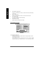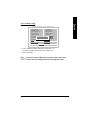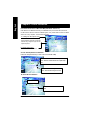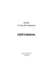
1
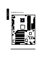
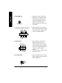
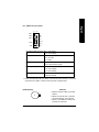
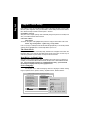
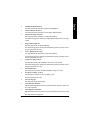
GA-8IRX
P4 Titan DDR Motherboard
USER’S MANUAL
Pentium® 4 P rocessor Motherboard
Rev. 2.0 First E dition
12M D-8I RX-2001
English
Table of Content
Item Checklist .................................................................................. 3
WARNING! ...................................................................................... 3
Chapter 1 Introduction ....................................................................... 4
Features Summary ................................................................................................ 4
GA-8IRX Motherboard Layout ............................................................................. 6
Chapter 2 Hardware Installation Process ............................................ 7
Step 1: Install the Central Processing Unit (CPU) ............................................ 8
Step 1-1 : CPU Installation ............................................................................. 8
Step 1-2 : CPU Heat Sink Installation ................................................................ 9
Step 2: Install memory modules ........................................................................ 10
Step 3: Install expansion cards .......................................................................... 11
Step 4: Connect ribbon cables, cabinet wires, and power supply ............... 12
Step 4-1 : I/O Back Panel Introduction ............................................................. 12
Step 4-2 : Connectors Introduction ................................................................. 14
Chapter 3 BIOS Setup .................................................................... 20
TheMain Menu ..................................................................................................... 20
SelectLanguage .................................................................................................. 20
Load Optimized Default ...................................................................................... 22
Save & Exit Setup ................................................................................................ 23
Chapter 4 Driver Installation ............................................................ 24
GA-8IRX Motherboard
-2 -
?
?
?
?
?
?
English
Item Checklist
The GA-8IRX motherboard
IDE cable x 1/ Floppy cable x 1
CD for motherboard driver & utility (IUCD)
GA-8IRX user’s manual
Quick PC Installation Guide
USB Cable x 1
WARNING!
Computer motherboards and expansion cards contain very delicate Integrated Circuit (IC) chips. To
protect them against damage from static electricity, y ou should follow some precautions whenever
you work on your computer.
1.
Unplug your computer w hen w orking on the inside.
2.
Use a grounded w rist strap before handling computer components. If y ou do not hav e
one, touch both of y our hands to a safely grounded object or to a metal object, such as
the pow er supply case.
Hold components by the edges and try not touch the IC chips, leads or connectors, or
other components.
Place components on a grounded antistatic pad or on the bag that came w ith the
components w henev er the components are separated from the sy stem.
Ensure that the ATX pow er supply is sw itched off before you plug in or remov e the ATX
3.
4.
5.
ow er connector on the motherboard.
Installing the motherboard to the chassis…
If the motherboard has mounting holes, but they don’t line up with the holes on the base and
there are no slots to attach the spacers, do not become alarmed y ou can still attach the spacers to
the mounting holes. Just cut the bottom portion of the spacers (the spacer may be a little hard to
cut off, so be careful of your hands). In this way y ou can still attach the motherboard to the base
without worrying about short circuits. Sometimes you may need to use the plastic springs to isolate
the screw from the motherboard PCB surface, because the circuit wire may be near by the hole. Be
careful, don’t let the screw contact any printed circuit write or parts on the PC B that are near the
fix ing hole, otherwise it may damage the board or cause board malfunctioning.
-3 -
Introduction
English
Chapter 1 Introduction
Features Summary
Form Factor
CPU
On-Board IDE
?
?
?
?
?
?
?
?
?
?
?
?
?
?
?
?
On-Board Peripherals
?
?
Chipset
Memory
I/O Control
Slots
Hardware Monitor
?
?
?
?
?
?
?
?
?
30.5cm x 22.8cm ATX size form factor, 4 layers PCB.
Socket 478 for Intel® Micro FC-PGA2 Pentium® 4 processor
Intel P entium® 4 400M Hz FSB
2nd cache depend on CPU
Chipset 82845 HOS T/AGP/Controller
82801BA(ICH2) I/ O Controller Hub
3 184-pin DDR DIMM sockets
Supports PC1600 DDR or PC2100 DDR DIMM
Supports up to 2GB DRAM (Max)
Supports only 2.5V DDR DIMM
Supports 64bit ECC type DRAM integrity mode
I T8712
1 CNR(Communication and Networking Riser) Slot
1 AGP slot 4X (1.5V) device support
6 PCI slot supports 33MHz & PCI 2. 2 compliant
An IDE controller on the Intel 82801BA PCI chipset
provides IDE HDD/CD-ROM with PIO, Bus Master (Ultra
DMA 33/ATA66/ATA100) operation modes.
Can connect up to four IDE devices
1 Floppy port supports 2 FDD with 360K, 720K,1.2M, 1.44M
and 2.88M bytes.
1 Parallel port supports Normal/EPP/ ECP mode
2 Serial ports (COMA&COMB)
4 USB ports (Rear USB x 2, Front USB x 2)
1 SC R connector
1 IrDA connector for IR
CPU/Power/ System Fan Revolution detect
CPU/Power/System Fan Control
CPU Overheat Warning
System Voltage Detect
to be continued.. ....
GA-8IRX Motherboard
-4 -
PS/2 Connector
BIOS
Additional Features
Special Features
?
?
?
?
?
?
?
?
?
?
?
?
?
?
?
?
?
Creative CT5880 Sound Chipset + Sigmatel 9708T CODEC
Line In/Line Out/Mic In/CD In/AUX_IN/Game Port
PS/2 Keyboard interface and PS/2 Mouse interface
Licensed AWARD BIOS, 4M bit x 2 FWH
Supports Dual BIOS
PS/2 Keyboard pow er on by password
PS/2 Mouse power on
External Modem w ake up
STR(Suspend-To-RAM)
Wake on LAN
AC Recovery
USB KB/Mouse wake up from S3
Supports @BIOS
Supports EasyTuneIII
Supports Multi Language
Over Voltage (DDR / AGP)
Over Clock (CPU / DDR)
Please set the CPU host frequency in accordance with your processor’s specifications.
We don’t recommend you to set the system bus frequency over the CPU’s specification
because these specific bus frequencies are not the standard specifications for C PU,
chipset and most of the peripherals. Whether your system can run under these specific
bus frequencies properly will depend on your hardware configurations, including CPU,
Chipsets,SDRAM,Cards… .etc.
-5 -
Introduction
English
On-B oard S ound
STR/DIMM_LED
CPU_FAN
KB_ MS
ATX
COMA
USB
AUX_12V
COMB
LPT1
SOCKET478
GA-8IRX
Brookdale
FLOPPY
IDE1
DDR3
PWR_FAN
CD_IN
DDR2
DDR1
AG P
IDE2
GAME
MIC_IN LINE_OUT
LINE_IN
F_AUDIO
PCI1
ICH2
AUX_IN
PCI2
AC97
PCI3
BATT ERY
P4 Titan-DDR
MAIN
BI OS
PCI4
PCI5
SYS
FAN
BAC KUP
BIOS
IT8712
CT5880
PCI6
CNR
GA-8IRX Motherboard
WOL
-6 -
CI
SCR
F_PANEL
English
GA-8IRX Motherboard Layout
IR
FRONT USB
English
Chapter 2 Hardware Installation Process
To set up your computer, you must complete the following setps:
Step 1- Install the Centr al Processing Unit ( CPU)
Step 2- Install memory modules
Step 3- Install expansion cards
Step 4- Connect ribbon cables, cabinet w ires, and power supply
Step 5- Setup BIOS softw are
Step 6- Install supporting software tools
Step4
Step1
Step 2
Step 4
Step 4
Step 4
Step3
-7 -
Hardware Installation Process
English
Step 1: Install the Central Processing Unit (CPU)
Step 1-1 CPU Installation
Pin1 indicator
Pin1indicator
CPU Top View
CPU Bottom View
Socket Actuation Lever
Pin1 indicator
1. Pull up the CP U socket lever
and up to 90-degree angle.
2. Locate Pin 1 in the socket and look
for a (golden) cut edge on the CPU
upper corner. Then insert the CPU
into the socket.
3. Press down the CPU socket
lever and finish CPU installation.
? Please make sure the CPU type is supported by the motherboard.
? If you do not match the CPU socket Pin 1 and CPU cut edge well, it will cause
improper installation. Please change the insert orientation.
GA-8IRX Motherboard
-8 -
English
Step 1-2 : CPU Heat Sink Installation
2. Hook the other end of the
cooler bracket to the CPU
socket.
1. Hook one end of the cooler
bracket to the C PU socket first.
? Please use Intel approved cooling fan.
? We recommend you to apply the thermal tape to provide better heat conduction between
your CPU and heatsink.
(The CPU cooling fan might stick to the CPU due to the hardening of the thermal paste.
During this condition if you try to remove the cooling fan, you might pull the processor out
of the CPU socket alone with the cooling fan, and might damage the processor. To avoid
this from happening, we suggest you to either use thermal tape instead of thermal paste, or
remove the cooling fan with extreme caution.)
? Make sure the CPU fan power cable is plugged in to the CPU fan connector, this completes
the installation.
? Please refer to CPU heat sink user’s manual for more detail installationprocedure.
-9 -
Hardware Installation Process
English
Step 2: Install memory modules
The motherboard has 3 dual inline memory module (DIM M) sockets, but it can only support a
maximum of 4 banks of DDR memory. DDR slot 1 uses 2 banks, DDR slot 2&3 share the remaining
2 banks. P lease refer to the follow ing tables for possible memory configurations supported. The
BIOS will automatically detects memory type and size. To install the memory module, just push it
vertically into the DIMM Slot . The DIM M module can only fit in one direction due to the notch.
Memory size can vary between sockets.
Total Memory Sizes With Unbuffered DDR DIMM
Dev ic es used on DIMM
1 DIMM x 64 / x 72
2 DIMMs x 64 / x 72
3 DIMMs x 64 / x 72
64 Mbit (2Mx 8x 4 banks)
64 Mbit (1Mx 16x 4 banks)
128 Mbit(4Mx 8x 4 banks)
128 Mbit(2Mx 16x 4 banks)
256 Mbit(8Mx 8x 4 banks)
256 Mbit(4Mx 16x 4 banks)
512 Mbit(16Mx 8x 4 banks)
512 Mbit(8Mx 16x 4 banks)
128MBytes
32 MBy tes
256MBytes
64 MBy tes
512MBytes
128MBytes
1 GBy tes
256MBytes
256MBytes
64 MBy tes
512MBytes
128MBytes
1 GBy tes
256MBytes
2 GBy tes
512MBytes
256MBytes
96 MBy tes
512MBytes
196MBytes
1 GBy tes
384MBytes
2 GBy tes
768MBytes
Notes: Double-sided x 16 DDR memory dev ices are not support by Intel 845 chipset.
DDR1
S
D
D
D
S
S
DDR2
S
S
D
X
D
X
DDR3
S
S
X
D
X
D
D:Double Sided DIMM S:Single Sided DIMM
X:Not Use
DDR
1. The DIMM slot has a notch, so the
DIMMmemory module can only fit in one direction.
2. Insert the DIMM memory module verticallyinto the
DIMM slot. Then push it down.
3. Close the plastic clip at both edges of theDIMM slots
to lock the DIMM module.
Reverse the installation steps when you wish to
remove the DIMM module.
? When STR/DIMM LED is ON, do not install/remove DIMM from socket.
? Please note that the DIMM module can only fit in one direction due to
the two notches. Wrong orientation will cause improper installation.
Please change the i nsert orientation.
GA-8IRX Motherboard
- 10 -
1. Read the related ex pansion card’s instruction document before install the expansion card into
the computer.
2. Remove your computer’s chassis cover, screws and slot bracket from the computer.
3. Press the expansion card firmly into expansion slot in motherboard.
4. Be sure the metal contacts on the card are indeed seated in the slot.
5. Replace the screw to secure the slot bracket of the expansion card.
6. Replace your computer’s chassis cover.
7. Power on the computer, if necessary, setup BIOS utility of expansion card from BIOS.
8. Install related driver from the operating system.
Please carefully pull out the small whitedraw able bar at the end of the AGP slot
when you try to install/ Uninstall the AGP
card. Please align the AGP card to the
onboard AGP slot and press firmly dow n on
the slot .M ake sure your AGP card is locked
by the small white- drawable bar.
AGP Card
Issues To Beware Of When Installing CNR
Please use standard CNR card like the one in order to avoid mechanical problem.
Standard CNR Card
- 11 -
Hardware Installation Process
English
Step 3: Install expansion cards
English
Step 4: Connect ribbon cables, cabinet wires, and power
supply
Step 4-1 : I/O Back Panel Introduction
?
?
?
?
?
? PS/2 Keyboard and PS/2 Mouse Connector
PS/2 Mouse Connector
(6 pin Female)
?This connector supports standard P S/2
keyboard and PS/2 mouse.
PS/2 K eyboard Connector
(6 pin Female)
? USB Connector
USB 0
USB 1
GA-8IRX Motherboard
?Before you connect your device(s) into USB
connector(s), please make sure your device(s)
such as USB keyboard, mouse, scanner, zip,
speaker..etc. Hav e a standard USB interface.
Also make sure your OS (Win 95 with USB
supplement, Win98, Windows 2000, Windows
ME, WinNT with SP 6) supports USB controller.
If your OS does not support USB controller,
please contact OS vendor for possible patch or
driver upgrade. For more information please
contact your OS or device(s) vendors.
- 12 -
Parallel Port
(25 pin Female)
?This connector supports 2 standard COM ports
and 1 Parallel port. Dev ice like printer can be
connected to Parallel port ; mouse and modem
etc can be connected to Serial ports.
COMA
COMB
Serial Ports (9 pin Male)
? Game /MIDI Ports
?This connector supports joystick, M IDI keyboard
and other relate audio devices.
Joystick/ MIDI (15 pin Female)
? Audio Connectors
Line O ut
Line In
MIC In
? After install onboard audio driver, you may connect
speaker to Line Out jack, micro phone to MIC In jack.
Device like C D-ROM , walkman etc can be connected
to Line-In jack.
Please note: Line Out 1: Line Out or SPDIF (The SPDIF
output is capable of providing digital audio to external
speakers or compressed AC3 data to an external Dolby
digital decoder). To enable SPDIF, simply insert SPDIF
connector into Line Out1. Line Out1 will become SPDIF
Out automatically.
To enable Four S peaker (for Creative 5880 audio only),
and Line I n will become Line Out2 to support second
pair of stereo speakers.
If you want to realize the “Four Speaker & SPDIF
“setup information in detail, please download
this manual from Gigabyte web
http://www.gigabyte.com.tw.
- 13 -
Hardware Installation Process
English
? Parallel Port and Serial Ports (COMA/COMB)
English
Step 4-2 :Connectors Introduction
A
R
B
C
D
E
Q
P
O
F
N
G
M
H
L K J I
A) CPU_FAN
J) IR/CIR
B) STR/DIMM_LED
K) SCR
C) ATX
L) WOL
D) FLOPPY
M) CI
E) IDE1/IDE2
N) BAT
F) PWR_FAN
O) AUX_IN
G) SYS_FAN
P) CD_IN
H) F_PANEL
Q) F_AUDIO
I) FRONT_USB
R) AUX_12V
GA-8IRX Motherboard
- 14 -
? This connector (ATX +12V) is
used only for CPU Core Voltage.
1 3
+12V
+12V
GND
GND
2 4
A) CPU_FAN (CPU Fan Connector)
? Please note, a proper installation of the CPU
cooler is essential to prevent the CPU from
running under abnormal condition or
damaged by overheating.The CPU fan
connector supports Max. current up to 600mA .
Sense
+12V/Control
1
GND
CPU_FAN
F) PWR_FAN (Power Fan Connector)
1
G) SYS_FAN (System Fan Connector)
GND
+12V/Control
Sense
1
C) ATX (ATX Power Con nector)
Sense
+12V/Control
GND
? AC power cord should
only be connected to
your power supply unit after ATX power
cable and other related dev ices are firmly
connected to the mainboard.
20
VCC
VCC
-5V
GND
GND
GND
PS-ON(SoftOn/Off)
GND
-12V
3.3V
+12V
5V SB (Stand by +5V)
Power Good
GND
VCC
GND
VCC
GND
3.3V
3.3V
1
- 15 -
Hardware Installation Process
English
R) AUX_12V( +12V Power Connector)
? Important Notice:
Please connect first harddisk to I DE1
and connect CDROM to IDE2.
IDE1
1
IDE2
1
D) FLOPPY (Floppy Connector)
P) CD_IN (CD Audio Line In Connector)
1
CD-R
GND
CD-L
1
O ) AUX_IN ( AUX In Connector)
L) WOL(Wake on LAN)
AUX-R
GND
AUX-L
English
E ) IDE1 / IDE2 Connector(Primary/Secondary]
1
+5V SB
GND
Signal
AUX_IN
1
GA-8IRX Motherboard
- 16 -
GND
NC
USB D3+
USB D3Power
? Be careful with the polarity of the front
panel USB connector. Check the pin
assignment while you connect the front
panel USB cable. P lease contact your
nearest dealer for optional front panel
USB cable.
Power
USB D2USB D2+
NC
GND
1
Incase speaker (L)
GND
GND
GND
Front Audio (R)
Front Audio (L)
Q) F_AUDIO (F_AUDIO Connector)
? If you want to use "Front Audio" connector,
you must move 11-12,13-14 Jumper. In order
to utilize the front audio header, your chassis
must have front audio connector. Also please
make sure the pin assigment on the cable is
the same as the pin assigment on the MB
header. To find out if the chassis you are buy
ing support front audio connector, please
contact your dealer.
Incase speaker (R)
GND
GND
+12V
MIC
Front Audio (R)
Front Audio (L) GND
1
- 17 -
Hardware Installation Process
English
I) FRONT_USB (Front USB Connector)
? Do not remove memory modules while
DIMM LED is on. It might cause short or
other unex pected damages due to the
2.5V stand by voltage. Remove memory
modules only when STR function is
disabled by jumper and AC Pow er cord is
disconnected.
STR/DIMM LED
NC
NC
DATA
NC
DATA
DATA
NC
K) SCR (Smart Card Reader Header)
? This MB supports smart card reader. To
enable smart card reader function an optional
smart card reader box is required. Please
contact your autherized distributor.
VCC
VCC
DATA
Clock
NC
GND
NC
1
NC
CIRRX
VCC
GND
NC
J) IR/CIR (IR/CIR )
1
VCC
NC
IRRX
GND
IRTX
English
B) STR/DIMM_LED
M) CI (CASE OPEN)
1
GA-8IRX Motherboard
? Make sure the pin 1 on the IR device is
aling w ith pin one the connector. To
enable the IR/ CIR function on the board,
you are required to purchase an option IR/
CIR module. For detail information please
contact y our autherized G iga-B yte
distributor.
To use IR function only, please connect IR
module to Pin1 to Pin5.
? This 2 pin connector allows y our system to
enable or disable the system alarm if the sys
tem case begin remove.
GND
Signal
- 18 -
13
14
English
H) F_PANEL (2x7 pins jumper)
RS TRST+
SPK+ 1
PW+
PWPD+
PD_GPD_Y-
SPK-
2
1
1 HD+
HD-
HD (IDE Hard Disk Active LED)
Pin 1: LED anode(+)
Pin 2: LED cathode(-)
SPK (S peaker Connector)
Pin 1: VCC(+)
Pin 2- Pin 3: NC
Pin 4: Data(-)
RST (Reset Sw itch)
Open: Normal Operation
Close: Reset H ardware System
PD+/PD_G-/PD_Y-(Power LED) Pin 1: LED anode(+)
Pin 2: LED cathode(-)
Pin 3: LED cathode(-)
PW (Soft Power Connector)
Open: Normal Operation
Close: Power On/Off
? Please connect the power LED, PC speaker, reset switch and power switch etc of your chassis
front panel to the F_PANEL connector according to the pin assignment above.
N) BAT (Battery)
CAUTION
+
? Danger of explosion if battery is incorrectly
replaced.
? Replace only with the same or equivalent
type recommended by the manufacturer.
? Dispose of used batteries according to the
manufacturer’s instructions.
- 19 -
Hardware Installation Process
English
Chapter 3 BIOS Setup
BIOS Setup is an overview of the BIOS Setup Program. The program that allows users to modify
the basic system configuration. This type of information is stored in battery-backed CMOS RAM so
that it retains the Setup information when the pow er is turned off.
ENTERING SETUP
After power on the computer, pressing <Del> immediately during POST (Power On Self Test) it will
allow you to enter Award BIOS CMOS SETUP.
GETTING HELP
Main Menu
The on-line description of the highlighted setup function is displayed at the bottom of the screen.
Status Page Setup Menu / Option Page Setup Menu
Press F1 to pop up a small help window that describes the appropriate keys to use and the possible
selections for the highlighted item. To exit the H elp Window press <E sc>.
The M ain M enu
Once y ou enter A ward BIOS CMOS Setup Utility, the Main M enu will appear on the screen. The
Main Menu allows you to select from eight setup functions and two exit choices. Use arrow keys to
select among the items and press <Enter> to accept or enter the sub-menu.
Dua l BIOS / Q-Flash Utility
After power on the computer, pressing <Del> immediately during POST (Power On Self Test) it
will allow you to enter Award BIOS CMOS SETUP, then press <F8> to enter DualBIOS/Q-Flash
utility. If you want to detail information for “DualBIOS/Q-Flash Utility “, please download
this manual from Gigabyte web http://www.gigabyte.com.tw.
Select Language
You can press <F3> to select multi language. There are 7 languages available, including
English, Japanese, French, Spanish, Germany, Simplified Chinese, Traditional Chinese.
CMOS Set up Utility-Cop yright (C) 198 4-2001 Award Software
?Standard CMOS Features
Select Language
?Advanced BIOS Features
Load Fail-Safe Defaults
?Advanced Chipset Features
Load Optimized Defaults
?IntegratedPeripherals
Set Supervisor Password
?Power Management Setup
Set UserPassword
?PnP/PCI Configurations
Save & Exit Setup
?PC Health Status
Exit Without Saving
?Frequency/VoltageControl
GA-8IRX Motherboard
- 20 -
u
English
?
Standard CMOS Features
This setup page includes all the items in standard compatible BI OS.
?
Advanced BIOS Features
This setup page includes all the items of Award special enhanced features.
?
Advanced Chipset Features
This setup page includes all the items of chipset special features.
We would not suggest you change the chipset default setting unless you really
need it.
?
Integrated Peripherals
This setup page includes all onboard peripherals.
We would not suggest you change the default setting unless you really need it.
For power End-User use only.
?
Power Management Setup
This setup page includes all the items of Green function features.
We would not suggest you change the default setting unless you really need it.
For power End-User use only.
?
PnP/PCI Configurations
This setup page includes all the configurations of PCI & PnP I SA resources.
We would not suggest you change the default setting unless you really need it.
For power End-User use only.
?
PC Health Status
This setup page is the System auto detect Temperature, voltage, fan, speed.
?
Frequency/Voltage Control
This setup page is control CPU’s clock and frequency ratio.
For power End-User use only.
?
Select Language
This setup page is select multi language.
?
Load Fail-Safe Defaults
Fail-Safe Defaults indicates the v alue of the system parameters which the sy stem w ould
be in safe configuration.
?
Load Optimized Defaults
Optimized Defaults indicates the value of the system parameters which the system w ould
be in best performance configuration.
- 21 -
BIOS Setup
English
?
Set Supervisor password
Change, set, or disable password. It allows you to limit access to the sy stem and S etup,
or just to Setup.
?
Set User password
Change, set, or disable password. It allows you to limit access to the system.
?
Save & Exit Setup
Save CMOS value settings to CMOS and exit setup.
?
Exit Without Saving
Abandon all CMOS value changes and exit setup.
Lo ad Optimize d D efault
CMOS Set up Utility-Cop yright (C) 198 4-2001 Award Software
?Standard CMOS Features
Select Language
?Advanced BIOS Features
Load Fail-Safe Defaults
?Advanced Chipset Features
Load Optimized Defaults
?IntegratedPeripherals
Set Supervisor Password
?Power Management Setup
Set UserPassword
?PnP/PCI Configurations
Save & Exit Setup
?PC Health Status
Exit Without Saving
?Frequency/VoltageControl
Load Optimized D efaults? ( Y/N)?Y
? Load Optimized Defaults
Selecting this field loads the factory defaults for B IOS and Chipset Features which the
system automatically detects.
To Load Optimized, move cursor, by pressing the arrow keys on the keyboard ,to highlight
the optimized default and press enter key then press "Y" if you decide to load this option.
GA-8IRX Motherboard
- 22 -
English
Sav e & Exit Setup
CMOS Set up Utility-Cop yright (C) 198 4-2001 Award Software
?Standard CMOS Features
Select Language
?Advanced BIOS Features
Load Fail-Safe Defaults
?Advanced Chipset Features
Load Optimized Defaults
?IntegratedPeripherals
Set Supervisor Password
?Power Management Setup
Set UserPassword
?PnP/PCI Configurations
Save & Exit Setup
SAVE to CMOS and EXIT (Y/N)?Y
?PC Health Status
Exit Without Saving
?Frequency/VoltageControl
? To save exit the BI OS setting screen press F10, and press "Y" if
you want to save setting. By typing "N" or "ESC" will take you
back to setup screen.
If you want to realize the BIOS setup information in detail, please download this manual from Gigabyte web http://www.gigabyte.com.tw.
- 23 -
BIOS Setup
English
Revision
ChapterHistory
4 Driver Intallation
Picture below are shown in Windows ME (IUCD driver version 1.9)
Insert the driver CD-title that came with your motherboard into your C D-ROM driv er, the driver
CD-title will auto start and show the installation guide. I f not, please double click the CD-ROM
device icon in "M y computer" , and execute the setup.exe.
A. Installing I ntel 845 Chipset Driver
Please install this driver as the first priority .
this item installs the chipset driv er utility that
enableds Plug-n-Plag INF support for Intel
chipset component.
B. Installing Sound Driver
Click this item to install sound driv er.
A: Intel 845 Chipset Driver Installation
Follow the setup that show ing on the scween to install the Utility.
A-1. Windows 9x/ME/2000/XP INF Update Utility
Click "Windows 9x/ME/2000/XP INF Update Utility"
item.
A-2. Intel Ultra ATA Storage Driver
Click "Intel Ultra ATA Storage Driver"item.
B: Sound Driver Installation
Revision History
1. 9
Press "Audio" icon.
1.Click "C reative CT5880 Sound Driver"
item.
GA-8IRX Motherboard
- 24 -