1
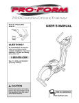
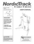
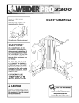
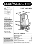
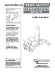
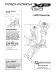
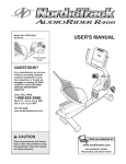
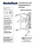
Model No. NTSA03991
Serial No.
USER’S MANUAL
The serial number is found in the
location shown below. Write the
serial number in the space above.
Serial Number Decal
QUESTIONS?
As a manufacturer, we are
committed to providing complete
customer satisfaction. If you
have questions, or if there are
missing parts, we will guarantee
complete satisfaction through
direct assistance from our factory.
TO AVOID UNNECESSARY
DELAYS, PLEASE CALL DIRECT
TO OUR TOLL-FREE CUSTOMER
HOT LINE. The trained technicians on our customer hot line
will provide immediate assistance, free of charge to you.
CUSTOMER HOT LINE:
1-888-825-2588
Mon.–Fri., 6 a.m.–6 p.m. MST
CAUTION
Read all precautions and instructions in this manual before using
this equipment. Save this manual
for future reference.
Visit our website at
www.nordictrack.com
new products, prizes,
fitness tips, and much more!
Table of Contents
Warning Decal Placement . . . . . . . . . . . . . . . . . . . . . . . . . . . . . . . . . . . . . . . . . . . . . . . . . . . . . . . . . . . . . . . 2
Important Precautions . . . . . . . . . . . . . . . . . . . . . . . . . . . . . . . . . . . . . . . . . . . . . . . . . . . . . . . . . . . . . . . . . . 3
Part Identification Chart . . . . . . . . . . . . . . . . . . . . . . . . . . . . . . . . . . . . . . . . . . . . . . . . . . . . . . . . . . . . . . . . . . 4
Assembly . . . . . . . . . . . . . . . . . . . . . . . . . . . . . . . . . . . . . . . . . . . . . . . . . . . . . . . . . . . . . . . . . . . . . . . . . . . 5
Adjustment . . . . . . . . . . . . . . . . . . . . . . . . . . . . . . . . . . . . . . . . . . . . . . . . . . . . . . . . . . . . . . . . . . . . . . . . . . 13
Using the Leg Press Accessory . . . . . . . . . . . . . . . . . . . . . . . . . . . . . . . . . . . . . . . . . . . . . . . . . . . . . . . . . . .13
Weight Resistance Chart . . . . . . . . . . . . . . . . . . . . . . . . . . . . . . . . . . . . . . . . . . . . . . . . . . . . . . . . . . . . . . . .14
Part List . . . . . . . . . . . . . . . . . . . . . . . . . . . . . . . . . . . . . . . . . . . . . . . . . . . . . . . . . . . . . . . . . . . . . . . . . . . . 14
Exploded Drawing . . . . . . . . . . . . . . . . . . . . . . . . . . . . . . . . . . . . . . . . . . . . . . . . . . . . . . . . . . . . . . . . . . . . . 15
Ordering Replacement Parts . . . . . . . . . . . . . . . . . . . . . . . . . . . . . . . . . . . . . . . . . . . . . . . . . . . . . .Back Cover
Limited Warranty . . . . . . . . . . . . . . . . . . . . . . . . . . . . . . . . . . . . . . . . . . . . . . . . . . . . . . . . . . . . . . .Back Cover
Warning Decal Placement
The warning decal shown above has been
attached to the leg press accessory in the location
shown. If the decal is missing, or if it is not legible,
please call our Customer Hot Line at the number
on the front cover for a free replacement decal.
Place the new decal on the leg press accessory in
the appropriate location.
NordicTrack® is a registered trademark of ICON Health & Fitness, Inc.
2
Important Precautions
WARNING:
To reduce the risk of serious injury, read the following important precautions before using the leg press accessory.
1. Read all instructions in this manual before
using the leg press accessory.
7. Keep children under the age of 12 and pets
away from the leg press accessory at all times.
2. It is the responsibility of the owner to ensure
that all users of the leg press accessory are
informed of all precautions.
8. Make sure all parts are properly tightened
before each use of the leg press accessory.
Replace any worn parts immediately.
3. Use the leg press accessory only on a level
surface. Cover the floor or carpet beneath the
leg press accessory to protect the floor.
9. The leg press accessory is designed to hold a
maximum user weight of 300 pounds.
10. Make sure the cables remain on the pulleys at
all times. If the cables bind while you are
exercising, stop immediately and make sure
the cables are on all of the pulleys.
4. The leg press accessory is designed to be
used only when the other stations of the
weight system are not in use.
5. Always wear athletic shoes for foot protection
when exercising.
11. If you feel pain or dizziness at any time while
exercising, stop immediately and begin cooling down.
6. Keep hands and feet away from moving parts.
WARNING:
Before beginning this or any exercise program, consult your physician. This
is especially important for persons over the age of 35 or persons with pre-existing health problems.
Read all instructions before using. ICON assumes no responsibility for personal injury or property
damage sustained by or through the use of this product.
3
Part Identification Chart
Refer to the drawings below to identify small parts used in assembly. The number in parentheses by each drawing is the key number of the part, from the PART LIST in the center of this manual. Note: Some small parts
may have been pre-attached. If a part is not in the parts bag, check to see if it has been pre-attached.
1/4" x 1 1/2" Bolt (131)
3/8" Flat Washer (120)
3/8" x 2" Bolt (121)
3/8" Nylon Locknut (118)
3/8" x 2 3/4" Bolt (125)
3/8" x 3" Bolt (117)
3/8" Nylon Jam Nut (122)
3/8" x 3" Carriage Bolt (115)
1/4" Nylon Locknut (128)
3/8" x 3 1/4" Bolt (124)
5/8” x 1/4” Spacer (127)
3/8" x 3 3/4" Bolt (110)
1/4" x 3/4" Bolt (130)
3/8" x 3 3/4" Carriage Bolt (119)
3/8" x 5" Bolt (123)
4
Assembly
Make sure you have the following tools:
Make Assembly Easier for Yourself
• Two adjustable wrenches
Everything in this manual is designed to
ensure that the leg press accessory can be
assembled successfully by anyone. Before
beginning assembly, make sure to read the
information on this page; this brief introduction will save you much more time than
it takes to read it.
• One rubber mallet
• You will also need grease or petroleum jelly, a
small amount of soapy water, and clear tape or
masking tape.
Note: Assembly will be more convenient if you have
a socket set, a set of open-end or closed-end
wrenches, or a set of ratchet wrenches.
Assembly Requires Two Persons
How to Identify Parts
For your convenience and safety, assemble the leg
press accessory with the help of another person.
To help you identify the small parts used in assembly,
we have included a Part Identification Chart on page
4. Use the chart to easily identify parts during each
assembly step. Note: Some small parts may have
been pre-attached. If a part is not in the parts
bag, check to see if it has been pre-attached.
How to Unpack the Box
To make assembly as easy as possible, we have
divided the assembly process into three stages.
The parts needed for each stage are found in individual bags. Important: Wait until you begin each
stage to open the parts bag for that stage. Place
all parts of the leg press accessory in a cleared
area and remove the packing materials. Do not dispose of the packing materials until assembly is completed.
Select a Location
Because of its weight and size, the leg press accessory should be assembled in the location where it
will be used. Make sure that there is enough room to
walk around the training system as you assemble it.
How to Orient Parts
Questions?
As you assemble the leg press accessory, make
sure that all parts are oriented exactly as shown in
the drawings.
If you have questions after reading the assembly
instructions, please call our Customer Service
Department toll-free at 1-888-825-2588 Monday
through Friday, 6 a.m. until 6 p.m. Mountain Time.
Tightening Parts
Tighten all parts as you assemble them, unless
instructed to do otherwise.
5
Frame Assembly
1
118
113
1. Before beginning assembly, make sure you have
read and understood the information on page 5.
116
118
Open the parts bags labeled “FRAME ASSEMBLY”
and “PULLEY.”
101
Attach the Press Base (101) to the Base Support
(103) with the 3/8” x 3 3/4” Carriage Bolt (119) and a
3/8” Nylon Locknut (118).
103
Attach a 4” Pulley (113) and a Cable Trap (116) to the
Base Support (103) with the 3/8” x 5” Bolt (123) and a
3/8” Nylon Locknut (118).
123
119
2
2. Remove the inner cap and the four hole plugs from
the end of the stabilizer.
Stabilizer
Inner Cap
Attach the Base Support (103) to the stabilizer with
two 3/8” x 2 3/4” Bolts (125), four 3/8” Washers (120),
and two 3/8” Nylon Locknuts (118).
118
Press the inner cap into the indicated end of the Base
Support (103).
120
Hole Plugs
103
125
120
Inner Cap
3. Attach the Handles (109) to the Seat Frame (106) with
four 1/4” x 1 1/2” Bolts (131) and four 1/4” Nylon
Locknuts (128). Make sure the heads of the Bolts
are inside of the hexagonal holes in the Handles.
3
112
Press a 2” Square Inner Cap (112) into the top of the
Seat Frame (106). Make sure there are two Seat
Frame Bushings (132) in the indicated ends of the
Seat Frame.
106
128
109
132
128
131
109
131
6
132
4. Slide the Press Frame (102) through the Seat Frame
(106).
4
129
Press a 2” Square Inner Cap (112) into the indicated
end of the Press Frame (102). Press a 2” Square
Angled Cap (126) onto the other end of the Press
Frame. Make sure the Support Plate (135 [not
shown]) is inside of the 2” Square Angled Cap.
106
112
126
102
5. Attach the Press Frame (102) to the Press Base (101)
with four 3/8” x 3” Carriage Bolts (115) and four 3/8”
Nylon Locknuts (118).
5
115
115
102
118
118
101
6. Press the 2” x 3” Inner Cap (136) into the end of the
Press Base (101).
112
6
Lubricate two 3/8” x 3 1/4” Bolts (124). Attach the
Rear and Forward Press Uprights (104, 105) to the
Press Base (101) with the Bolts and two 3/8” Nylon
Locknuts (118). Note: The Rear Press Upright has
an extra hole halfway down the side. Do not overtighten the Bolts; the Press Uprights must be
able to pivot freely.
104
105
Press two 2” Square Inner Caps (112) into the Rear
and Forward Press Uprights (104, 105).
7. Lubricate two 3/8” x 3 1/4” Bolts (124). Attach the
Press Plates (108) to the Rear and Forward Press
Uprights (104, 105) with the Bolts and two 3/8” Nylon
Jam Nuts (122). Do not over tighten the Bolts; the
Press Uprights must be able to pivot freely.
124
101
Lubricate
136
118
7
124
104
108
122
7
108
105
Lubricate
8
Cable Assembly
122
8. Open the parts bag labeled “CABLE ASSEMBLY.”
120
127
Attach the Cable (133) to the indicated hole in the
Press Base (101) with a 3/8” x 3” Bolt (117), two 3/8”
Washers (120), a 5/8” x 1/4” Spacer (127), and a 3/8”
Nylon Jam Nut (122). Do not over tighten the Nylon
Jam Nut; the Cable must be able to pivot easily.
133
120
117
101
9. Wrap the Cable (133) up around a 4” Pulley (113) and
attach the Pulley and a Cable Trap (116) to the Rear
Press Upright (104) with a 3/8” x 3 3/4” Bolt (110), a
3/8” Washer (120), and a 3/8” Nylon Locknut (118).
Make sure the Cable is routed in the direction
shown.
9
110
113
133
116
120
118
10. Wrap the Cable (133) under a 4” Pulley (113) and
attach the Pulley and a Cable Trap (116) to the Base
Frame (101) with a 3/8” x 3 3/4” Bolt (110), a 3/8”
Washer (120), and a 3/8” Nylon Locknut (118). Make
sure the Cable is routed in the direction shown.
104
10
101
110
113
116
133
118
11. Insert the end of the Cable (133) between the 4”
Pulley (113) and the Cable Trap (116) assembled in
step one.
120
11
133
116
113
8
12. Wrap the Cable (133) under a 4” Pulley (113) and
attach the Pulley and a Cable Trap (116) to the welded bracket on the stabilizer with a 3/8” x 2” Bolt (121)
and a 3/8” Nylon Locknut (118).
12
113
116
121
IMPORTANT: If you are assembling the leg
press accessory and your weight system at the
same time, continue with Assembly Option A,
below. If your weight system is already assembled,
continue with Assembly Option B, on page 11.
Note: At this point, you will begin using parts from
both the leg press accessory and your weight system. Pay attention to key numbers as they will correspond to two different part lists.
Bracket
133
118
13
91
25
Assembly Option A
71
13. Locate the Pulley Bracket (91), a 1/4” Flat Washer
(71), and a 1/4” Nylon Locknut (25) that came with
your weight system. Attach the end of the Cable (133)
to the Pulley Bracket with the Flat Washer and the
Nylon Locknut.
14. Install the High Cable (73) to the stage shown at
the right as instructed in your weight system
manual. Then, substitute the following steps for
those in the manual to complete the installation of
the High Cable.
133
14
35
44
63
Wrap the High Cable (73) under a 4” Pulley (35) and
attach the Pulley and a Cable Trap (44) to the top
hole in the Pulley Bracket (91) with a 3/8” x 1 3/4”
Bolt (60) and a 3/8” Nylon Jamnut (63).
73
60
91
15. Wrap the High Cable (73) up around a 4” Pulley (35)
in the direction shown and attach the Pulley inside
the Top Frame (1) with a 3/8” x 2 1/2” Bolt (54), two
3/8” Flat Washers (55), two 5/8” x 1/2” Pulley
Bushings (42), and a 3/8” Nylon Jamnut (63).
15
73
35
63
1
55
42
55
54
9
16. Wrap the High Cable (73) around a 4” Pulley (35) in
the direction shown and attach the Pulley inside the
Top Frame (1) with a 3/8” x 2 1/2” Bolt (54), two 3/8”
Flat Washers (55), two 5/8” x 1/2” Pulley Bushings
(42), and a 3/8” Nylon Jamnut (63).
16
42
35
42
63
55
1
55
54
73
17. Thread the 1/2” Plain Nut (68) part way onto the bolt
at the end of the High Cable (73).
Place the 1 1/2” Flat Washer (40) on top of the
Weight Tube (36) and the 5 7/8” Long Bushing (76).
Tighten the bolt at the end of the High Cable (73) into
the threaded hole in the Weight Tube (36).
When all Cables (73, 72 [not shown], 133 [not shown])
are tight, tighten the 1/2” Plain Nut (68) against the
1 1/2” Flat Washer (40).
Go to the Seat And Plate Assembly section on
page 12 and continue with step 18.
10
17
73
68
40
76
36
13
Assembly Option B
73
13. Loosen the 1/2” Plain Nut (68) on the bolt at the end
of the High Cable (73). Detach the bolt from the top
of the Weight Tube (36) and the 5 7/8” Long Bushing
(76).
68
40
76
36
Remove the 1 1/2” Flat Washer (40) and the 5 7/8”
Long Bushing (76). Put them where you can easily
find them later.
14. Locate the Pulley Bracket (91) on your weight system. Detach the Pulley Bracket from the Top Frame
(1) and discard the 1/4” x 3 3/4” Bolt (92). Save the
1/4” Flat Washer (71) and the 1/4” Nylon Locknut (25).
14
92
1
Remove the 4” Pulley (35), the Cable Trap (44), the
3/8” x 1 3/4” Bolt (60), and the 3/8” Nylon Jamnut (63)
from the Pulley Bracket. Put them where you can
easily find them later.
73
91
25
71
63
Note: This step will leave a loop of the High Cable
(73) hanging from the Top Frame (1). This is required
for the next step.
15. Turn the Pulley Bracket (91) over and attach the end
of the Cable (133) to the Pulley Bracket with the 1/4”
Washer (71) and the 1/4” Nylon Locknut (25)
removed in step 14.
44
15
35
73
35
63
Wrap the loop of High Cable (73) around the 4”
Pulley (35) that was removed in step 14. Attach the
Pulley and the Cable Trap (44) to the top hole in the
Pulley Bracket (91) with the 3/8” x 1 3/4” Bolt (60)
and the 3/8” Nylon Jamnut (63) removed in step 14.
44
25
60
71
91
133
16. Replace the 1 1/2” Flat Washer (40) on top of the
Weight Tube (36).
16
73
Tighten the bolt at the end of the High Cable (73) into
the threaded hole in the Weight Tube (36).
When all Cables (73, 72 [not shown], 133 [not shown])
are tight, tighten the 1/2” Plain Nut (68) against the
1 1/2” Flat Washer (40).
Go to the Seat And Plate Assembly section on
page 12 and continue with step 18.
11
60
68
40
36
18
Seat and Plate Assembly
106
18. Open the parts bag labeled “SEAT ASSEMBLY.”
111
Attach the Seat (111) to the Seat Frame (106) with
four 1/4” x 3/4” Bolts (130).
130
19. Attach the Backrest (134) to the Seat Frame (106)
with four 1/4” x 3/4” Bolts (130).
19
134
130
106
20. Attach the Foot Press (107) to the Press Plates (108)
with two 3/8” x 3 1/4” Bolts (124), eight 3/8” Washers
(120), and two 3/8” Nylon Jam Nuts (122).
20
108
107
Note: All eight of the 3/8” Flat Washers (120) must
be between the Press Plates (108) and the welded
tube on the Foot Press (107).
124
120
120
122
12
Adjustment
The instructions below describe how the leg press accessory can be adjusted. IMPORTANT: If there is any
slack in the cables as an exercise is performed, the effectiveness of the exercise will be reduced.
Adjusting the Seat
To adjust the position of the Seat Frame (106), unscrew
the handle of the Adjustment Knob (129) until it is loose.
Pull out the handle as far as it will go and slide the Seat
Frame to the desired position. Release the handle and
engage the Adjustment Knob into one of the adjustment
holes in the Press Frame (102). Retighten the handle.
106
129
102
Using the Leg Press Accessory
To exercise with the leg press accessory, select the appropriate amount of weight from the weight stack and follow the directions below.
For the approximate weight resistance of each weight plate, see the chart on page 14.
LEG PRESS
Sit on the bench and place your feet on the plate as
shown. Press forward until your legs are fully extended.
Do not lock your knees. Return to the starting position.
Starting
Muscles affected: quadriceps, gastrocnemius
Ending
CALF PRESS
Sit on the bench and place your feet on the plate. Keep
your arms at your sides and push the plate as far as
possible with your toes, pushing up your heels. Return
to the starting position.
Muscles affected: gastrocnemius
13
Weight Resistance Chart
This chart shows the approximate weight resistance for the leg press accessory. “Top” refers to the 10 lb. top
weight. The other numbers refer to the 10 lb. weight plates. Note: The actual resistance may vary due to differences in individual weight plates as well as friction between the cables, pulleys, and weight guides.
Weight
Plates
Leg
Press
(lbs.)
Weight
Plates
Leg
Press
(lbs.)
Top
28
10
259
1
51
11
282
2
74
12
305
3
97
13
328
4
120
14
351
5
143
15
374
6
167
16
397
7
190
17
420
8
213
18
443
9
236
19
466
Part List—Model No. NTSA03991
Key No.
Qty.
101
102
103
104
105
106
107
108
109
110
111
112
113
114
115
116
117
118
119
1
1
1
1
1
1
1
2
2
2
1
4
4
2
4
4
1
13
1
Description
R0602A
Key No.
Qty.
120
121
122
123
124
125
126
127
128
129
130
131
132
133
134
135
136
#
16
1
5
1
6
2
1
1
4
1
8
4
2
1
1
1
1
1
Press Base
Press Frame
Base Support
Rear Press Upright
Forward Press Upright
Seat Frame
Foot Press
Press Plate
Handle
3/8” x 3 3/4” Bolt
Seat
2” Square Inner Cap
4” Pulley
Hand Grip
3/8” x 3” Carriage Bolt
Cable Trap
3/8” x 3” Bolt
3/8” Nylon Locknut
3/8” x 3 3/4” Carriage Bolt
Description
3/8” Washer
3/8” x 2” Bolt
3/8” Nylon Jam Nut
3/8” x 5” Bolt
3/8” x 3 1/4” Bolt
3/8” x 2 3/4” Bolt
2” Square Angle Cap
5/8” x 1/4” Spacer
1/4” Nylon Locknut
Adjustment Knob
1/4” x 3/4” Bolt
1/4” x 1 1/2” Bolt
Seat Frame Bushing
Cable
Backrest
Support Plate
2” x 3” Inner Cap
User’s Manual
Note: “#” indicates a non-illustrated part. Specifications are subject to change without notice.
14
131
114
116
109
132
113
129
128
121
1•0
130
15
118
120
113
118
118
106
128
112
119
118
116
112
103
120
123
115
132
131
109
1 16
118
114
101
125
12 0
1 13
110
102
117
1 18
118
115
122
111
134
120
120
133
127
118
135 126
112
122
124
108
104
112
116
122
105
136
124
124
133
113
107
110
120
120
124
Exploded Drawing—Model No. NTSA03991
R0602A
Ordering Replacement Parts
To order replacement parts, simply call our Customer Service Department toll-free at 1-888-825-2588, Monday
through Friday, 6 a.m. until 6 p.m. Mountain Time (excluding holidays). To help us assist you, please be prepared to give the following information:
• The MODEL NUMBER of the product (NTSA03991)
• The NAME of the product (NordicTrack® Leg Press Accessory)
• The SERIAL NUMBER of the product (see the front cover of this manual)
• The KEY NUMBER and DESCRIPTION of the part(s) (see the PART LIST and EXPLODED DRAWING on
pages 14 and 15)
Limited Warranty
WHAT IS COVERED—The entire NordicTrack® Leg Press Accessory (“Product”) is warranted to be free of all defects in material and
workmanship.
WHO IS COVERED—The original purchaser or any person receiving the Product as a gift from the original purchaser.
HOW LONG IS IT COVERED—ICON Health & Fitness, Inc. (“ICON”), warrants the product frame for five years after the date of purchase. ICON warrants all other parts for one year after the date of purchase. Labor is covered for one year.
WHAT WE DO TO CORRECT COVERED DEFECTS—We will ship to you, without charge, any replacement part or component, providing the repairs are authorized by ICON first and are performed by an ICON trained and authorized service provider, or, at our
option, we will replace the Product.
WHAT IS NOT COVERED—Any failures or damage caused by unauthorized service, misuse, accident, negligence, improper assembly or installation, alterations, modifications without our written authorization or by failure on your part to use, operate, and maintain
as set out in your User’s Manual (“Manual”).
WHAT YOU MUST DO—Always retain proof of purchase, such as your bill of sale; store, operate, and maintain the Product as specified in the Manual; notify our Customer Service Department of any defect within 10 days after discovery of the defect; as instructed, return any defected part for replacement or, if necessary, the entire product, for repair.
USER’S MANUAL—It is VERY IMPORTANT THAT YOU READ THE MANUAL before operating the Product. Remember to do the
periodic maintenance requirements specified in the Manual to assure proper operation and your continued satisfaction.
HOW TO GET PARTS AND SERVICE—Simply call our Customer Service Department at 1-888-825-2588 and tell them your name
and address and the serial number of your Product. They will tell you how to get a part replaced, or if necessary, arrange for service
where your Product is located or advise you how to ship the Product for service. Before shipping, always obtain a Return
Authorization Number (RA No.) from our Customer Service Department; securely pack your Product (save the original shipping carton if possible); put the RA No. on the outside of the carton and insure the product. Include a letter explaining the product or problem and a copy of your proof of purchase if you believe the service is covered by warranty.
ICON is not responsible or liable for indirect, special or consequential damages arising out of or in connection with the use or performance of the product or damages with respect to any economic loss, loss of property, loss of revenues or profits, loss of enjoyment or use, costs of removal, installation or other consequential damages of whatsoever nature. Some states do not allow the exclusion or limitation of incidental or consequential damages. Accordingly, the above limitation may not apply to you.
The warranty extended hereunder is in lieu of any and all other warranties and any implied warranties of merchantability or fitness
for a particular purpose is limited in its scope and duration to the terms set forth herein. Some states do not allow limitations on how
long an implied warranty lasts. Accordingly, the above limitation may not apply to you.
No one is authorized to change, modify or extend the terms of this limited warranty. This warranty gives you specific legal rights and
you may have other rights which vary from state to state.
ICON HEALTH & FITNESS, INC., 1500 S. 1000 W., LOGAN, UT 84321-9813
Part No. 186131 R0602A
Printed in Canada © 2002 ICON Health & Fitness, Inc.