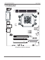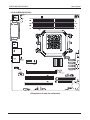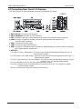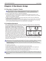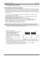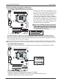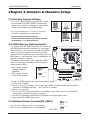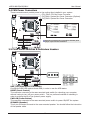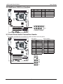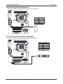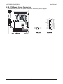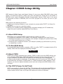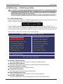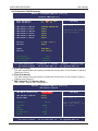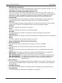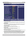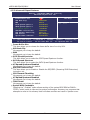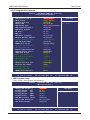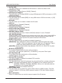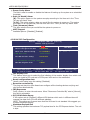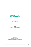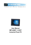
1
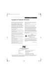
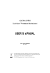
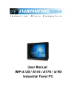
The Possible Of Impossible
nVIDIA N61P/N61S/N61V
Socket AM2 Processor Mainboard
nVIDIA MCP61 Series
User Manual
Website: http://www.jwele.com
Rev: 1.00, Aug 2007
P/N: 80ENN61PV0
Disclaimer
The intellectual property of this manual belongs to our company. The ownership of all of the
products, including accessories and software etc. belong to our company. No one is permitted to
copy, change, or translate without our written permission.
We compiled this manual based on our careful attitude, but we can not guarantee the accuracy
of the contents. This manual is purely technical documentation, without any hint or other
meanings, and we won't commit users' misunderstanding of the typesetting error.
Our products are in continuous improvement and updating, Therefore, we retain the right that
we won't give notice to the users in future.
Copyright
All of the trademark in this manual belong to their own registered company.
All of the products name is only for identification, its title belongs to its manufacturer or brand
owner.
Table of Contents
Chapter 1 Introduction ........................................................................ 3
1.1 Package Checklist ............................................................................................... 3
1.2 Specifications ...................................................................................................... 4
1.3 Mainboard Layout ............................................................................................... 5
1.3.1 nVIDIA N61(V1.0) ........................................................................................................... 5
1.3.2 nVIDIA N61(V2.0) ........................................................................................................... 6
1.4 Connecting Rear Panel I/O Devices ................................................................... 7
Chapter 2 Hardware Setup .................................................................. 8
2.1 Choosing a Computer Chassis ............................................................................. 8
2.2 Installing Mainboard ........................................................................................... 8
2.3 Installation of the CPU and CPU Cooler............................................................... 9
2.3.1 Installation of the CPU .................................................................................................... 9
2.3.2 Installation of the CPU Cooler ....................................................................................... 10
2.4 Installation of Memory Modules........................................................................ 10
2.5 Connecting Peripheral Devices.......................................................................... 11
2.5.1 Floppy and IDE Disk Drive Connectors ............................................................................ 11
2.5.2 Serial ATA Connectors ..................................................................................................... 11
2.5.3 PCI and PCI Express slots ............................................................................................... 11
Chapter 3 Jumpers & Headers Setup ................................................ 12
3.1 Checking Jumper Settings ................................................................................ 12
3.2 CMOS Memory Clearing Header ........................................................................ 12
3.3 Keyboard Power Function ................................................................................. 12
3.4 FAN Power Connectors ...................................................................................... 13
3.5 Front Panel Switches & Indicators Headers ..................................................... 13
3.6 Additional USB Port Headers ............................................................................ 14
3.7 Front Panel Audio Connection Header............................................................... 14
3.8 Internal Audio Connectors ................................................................................ 15
3.9 IR Connection Header........................................................................................ 15
3.10 ATX Power Input Connectors .......................................................................... 16
Chapter 4 BIOS Setup Utility ............................................................. 17
4.1 About BIOS Setup ................................................................................................ 17
4.2 To Run BIOS Setup .............................................................................................. 17
4.3 About CMOS............................................................................................................. 17
4.4 The POST (Power On Self Test).......................................................................... 17
4.5 BIOS Setup — CMOS Setup Utility..................................................................... 18
4.5.1 CMOS Setup Utility ........................................................................................................ 18
4.5.2 Control Keys .................................................................................................................. 19
4.5.3 Standard CMOS Features .............................................................................................. 20
4.5.4 Advanced BIOS Features ............................................................................................... 22
4.5.5 Advanced Chipset Features ........................................................................................... 24
4.5.6 Integrated Peripherals .................................................................................................. 25
4.5.7 Power Management Setup ............................................................................................ 29
4.5.8 PnP PCI Configuration ................................................................................................... 30
4.5.9 PC Health Status ............................................................................................................ 31
4.5.10 Frequency/Voltage Control ......................................................................................... 31
4.5.11 Load Fail-Safe Defaults ................................................................................................ 33
4.5.12 Load Optimized Defaults .............................................................................................. 33
4.5.13 Set Supervisor/User Password .................................................................................... 33
4.5.14 Save & Exit Setup ........................................................................................................ 34
4.5.15 Exit Without Saving ..................................................................................................... 34
Chapter 5 Driver Installation ...... ...................................................... 35
nVIDIA N61P/N61S/N61V
User Manual
Chapter 1 Introduction
1.1 Package Checklist
Thank you for choosing our product.
Please check the following packing and accessories, if there is any broken or part missing,
please contact with your franchiser.
•
•
•
•
•
•
•
HDD Cable X 1
Serial ATA Cable X 1
Rear I/O Panel X 1
User's Manual X 1
Driver/Utility CD X 1
FDD Cable X 1 (Optional)
Serial ATA Power Cable X 1 (Optional)
The items listed above are for reference only, and are subject to change without notice.
--
nVIDIA N61P/N61S/N61V
User Manual
1.2 Specifications
- Socket AM2 for AMD® AthlonTM 64/AhtlonTM 64 FX/AthlonTM 64 X2/
SempronTM Processor
- AMD 64 Architecture enables 32 and 64 bit computing
CPU
- Supports up to 1GHz Bandwidth
- Supports Hyper Transport
- Supports AMD CPU Cool 'n' Quiet Technology
Chipset
- Based on nVIDIA MCP61P/S/V chipset
Graphics
- Integrated nVIDIA Geforce 6100
- 2 x 240-pin DIMM slots support (for nVIDIA N61(V1.0) Only)
Main Memory
- 4 x 240-pin DIMM slots support (for nVIDIA N61(V2.0) Only)
- Supports Dual Channel DDRII 533/667/800MHz
- Supports Plug&Play
BIOS
- Supports Advanced Power Management ACPI
- CPU temperature, Fan speed, System Voltage monitoring
- 1 x PS/2 Keyboard port
- 1 x PS/2 Mouse port
- 1 x VGA port
- 1 x COM port
- 1 X LPT connector
- 1 x IR port (optional)
Integrate Ports - 8 x USB 2.0 ports, USB 1.1 is compliant
- 2 x SATAII 3Gb/s
- 4 x SATAII 3Gb/s supports SATA RAID 0,1,0+1 (for MCP61P chipset
only)
- 1 x IDE connector, 2 x IDE devices could be connected,
support ATA 66/100/133
- 1 x Floppy Drive, supports 360K/720K/1.2M/1.44M/2.88M floppy disk
- Onboard 6-channel/8-channel HD Audio Codec (Optional)
- Supports 16/24 bit Audio Codec
Sound
- Positioning Audio Support A3D, I3DL2
- Front Panel Jumper, provides stereo MIC port on front panel
Onboard LAN
- Onboard 10/100/1000Mb compatible LAN (Optional)
- 1 x PCI Express x16 slot (MCP61P chipset at works 16x, MCP61S
chipset at works 8x, MCP61V chipset at works 1x)
Expansion Slots - 1 x PCI Express x1 slot (for nVIDIA N61(V2.0) only)
- 2 x PCI slots
- Support PCI Bus interface v2.2 compliant
Form Factor
- Micro-ATX
--
nVIDIA N61P/N61S/N61V
User Manual
1.3 Mainboard Layout
1.3.1 nVIDIA N61(V1.0)
(This picture is only for reference)
--
nVIDIA N61P/N61S/N61V
User Manual
1.3.2 nVIDIA N61(V2.0)
(This picture is only for reference)
--
nVIDIA N61P/N61S/N61V
User Manual
1.4 Connecting Rear Panel I/O Devices
The rear I/O part of this mainboard provides the following I/O ports:
• PS/2 Mouse: Connect to PS/2 mouse.
• PS/2 Keyboard: Connect to PS/2 keyboard.
• LPT: Connect to printer or other devices that support this communication protocol.
• COM: Connect to external modem, mouse or other devices that support this
communication protocol.
• VGA: Connect to monitor input.
• LAN: Connect to Local Area Network.
• USB: Connect to USB devices such as scanner, digital speakers, monitor, mouse, keyboard,
hub, digital camera, joystick etc.
• AUDIO1:
Cen./Sub. (Center / Subwoofer): Connect to the center and subwoofer channel in the 7.1
channel audio system.
R.L./R.R. (Rear Left / Rear Right): Connect to the rear left and rear right channel in the 7.1
channel audio system.
S.L./S.R. (Surround Left / Surround Right): Connect to the surround left and surround right
channel in the 7.1 channel audio system.
Line-In: Connect to the line out from external audio sources.
Line-Out: Connect to the front left and front right channel in the 7.1-channel or regular
2-channel audio system.
Mic-In: Connect to the plug from external microphone.
--
nVIDIA N61P/N61S/N61V
User Manual
Chapter 2 Hardware Setup
2.1 Choosing a Computer Chassis
The mainboard and its component layouts illustrated in this chapter were
based mainly on model “nVIDIA N61(V1.0)”, unless specifically stated.
• Choose a chassis big enough to install this mainboard.
• As some features for this mainboard are implemented by cabling connectors on the
mainboard to indicators and switches or buttons on the chassis, make sure your chassis
supports all the features required.
• If there is possibility of adopting some more hard drives, make sure your chassis has
sufficient power and space for them.
• Most chassis have alternatives for I/O shield located at the rear panel. Make sure the I/O
shield of the chassis matches the I/O port configuration of this mainboard. You can find
an I/O shield specifically designed for this mainboard in its package.
2.2 Installing Mainboard
Most computer chassis have a base with many mounting holes to allow the mainboard to
be securely attached, and at the same time, prevent the system from short circuits. There
are two ways to attach the mainboard to the
chassis base: (1) with studs, or (2) with spacers.
Basically, the best way to attach the board is with
studs. Only if you are unable to do this should you
attach the board with spacers. Line up the holes on
the board with the mounting holes on the chassis.
If the holes line up and there are screw holes, you
can attach the board with studs. If the holes line
up and there are only slots, you can only attach with
spacers. Take the tip of the spacers and insert them
into the slots. After doing this to all the slots, you can slide the board into position aligned
with slots. After the board has been positioned, check to make sure everything is OK before
putting the chassis back on.
Always power off the computer and unplug the AC power cord before adding or removing
any peripheral or component. Failing to do so may cause severe damage to your
mainboard and/or peripherals. Plug in the AC power cord only after you have carefully
checked everything.
To install this mainboard:
1. Locate all the screw holes on the mainboard and the chassis base.
2. Place all the studs or spacers needed on the chassis base and have them tightened.
3. Face the mainboard’s I/O ports toward the chassis’s rear panel.
4. Line up all the mainboard’s screw holes with those studs or spacers on the chassis.
5. Install the mainboard with screws and have them tightened.
To prevent shorting the PCB circuit, please REMOVE the metal studs or spacers if they are
already fastened on the chassis base and are without mounting-holes on the mainboard to
align with.
--
nVIDIA N61P/N61S/N61V
User Manual
2.3 Installation of the CPU and CPU Cooler
Before installing the CPU, please comply with the following conditions:
1. Please make sure that the mainboard supports the CPU.
2. Please take note of the one indented corner of the CPU. If you install the CPU in the wrong
direction, the CPU will not insert properly. If this occurs, please change the insert direction
of the CPU.
3. Please add an even layer of heat sink paste between the CPU and CPU cooler.
4. Please make sure the CPU cooler is installed on the CPU prior to system use, otherwise
overheating and permanent damage of the CPU may occur.
5. Please set the CPU host frequency in accordance with the processor specifications. It is not
recommended that the system bus frequency be set beyond hardware specifications since
it does not meet the required standards for the peripherals. If you wish to set the frequency beyond the proper specifications, please do so according to your hardware
specifications including the CPU, graphics card, memory, hard drive, etc.
2.3.1 Installation of the CPU
1. Unlock the socket by pressing the
lever sideways, then lift it up to a 90 .
2. Position the CPU above the socket such
that the CPU corner with the gold
triangle matches the socket corner with
a small triangle.
3. Carefully insert the CPU into the socket
until it fits place.
o
Figure 1
4. When the CPU is in place, push down
the socket lever to secure the CPU.
The lever clicks on the side tab to
indicate that it is locked.
Figure 2
Figure 3
--
nVIDIA N61P/N61S/N61V
User Manual
2.3.2 Installation of the CPU Cooler
For proper installation, please kindly refer to the instruction manuals of your CPU Cooler.
2.4 Installation of Memory Modules
This mainboard provides four 240-pin DDRII (Double Data Rate) DIMM slots, and supports
Dual Channel Memory Technology. For dual channel configuration, you always need to install
two identical (the same brand, speed, size and chip-type) memory modules in the DDRII
DIMM slots to activate Dual Channel Memory Technology. Otherwise, it will operate at single
channel mode.
To reach the performance of Dual Channel DDR2, the following rules must be obeyed:
For 2-DIMM dual-channel installation:
Populate DIMM modules of the same type and size on slots [DDR1]+[DDR2], or slots
[DDR3]+[DDR4] (for nVIDIA N61(V2.0) Only).
For 4-DIMM dual-channel installation: (for nVIDIA N61(V2.0) Only)
Populate 2 DIMM modules of the same type and size on slots [DDR1]+[DDR2], and
another 2 DIMM modules of the same type and size on slots [DDR3]+[DDR4] .
[DDR1] and [DDR2] slots are made of the same color.
[DDR3] and [DDR4] are made of another same color.
Static electricity can damage the electronic components of the computer or optional
boards. Before starting these procedures, ensure that you are discharged of static
electricity by touching a grounded metal object briefly.
To install system memory:
Notch Key
Mounting Notch
1. Power off the computer and unplug the
AC power cord before installing or
removing memory modules.
2. Locate the DIMM slot on the board.
3. Hold two edges of the DIMM module
carefully, keep away from touching its
connectors.
Rib
4. Align the notch key on the module with
Ejector
Tab
the rib on the slot.
5. Firmly press the module into the slots until the ejector tabs at both sides of the slot
automatically snap into the mounting notch. Do not force the DIMM module in with extra
force as the DIMM module only fits in one direction.
6. To remove the DIMM modules, push the two ejector tabs on the slot outward
simultaneously, and then pull out the DIMM module.
- 10 -
nVIDIA N61P/N61S/N61V
User Manual
2.5 Connecting Peripheral Devices
2.5.1 Floppy and IDE Disk Drive Connectors
Each of the IDE port connects up to
two IDE drives at Ultra ATA 66/100/133
mode by one 40-pin, 80-conductor,and
3-connector Ultra ATA/66 ribbon cables.
Connect the single end (blue connector)
at the longer length of ribbon cable to
the IDE port of this board, the other two
ends (gray and black connector) at the
shorter length of the ribbon cable to the
connectors of your hard drives.
Make sure to configure the “Master” and “Slave”
relation before connecting two drives by one
single ribbon cable. The red line on the ribbon
cable must be aligned with pin-1 on both the IDE
port and the hard-drive connector.
The FDD connector connects up to two floppy drives with a 34-wire, 2-connector floppy
cable.Connect the single end at the longer length of ribbon cable to the FDD on the board,
the two connectors on the other end to the floppy disk drives connector. Generally you need
only one floppy disk drive in your system.
The red line on the ribbon cable must be aligned with pin-1 on both the FDD port and the floppy connector.
2.5.2 Serial ATA Connectors
Each SATA connector serves as one single channel to connect one SATA device by SATA
cable.
2.5.3 PCI and PCI Express slots
Install PCI Express X16 graphics card into slot “PCIEXP1”.
Install PCI Experess X1 card into slot "PCIE". (for nVIDIA N61(V2.0) only)
Install PCI cards into slots “PCI1” and/or “PCI2”.
- 11 -
nVIDIA N61P/N61S/N61V
User Manual
Chapter 3 Jumpers & Headers Setup
3.1 Checking Jumper Settings
• For a 2-pin jumper, plug the jumper cap on both
pins will make it CLOSE (SHORT). Remove the
jumper cap, or plug it on either pin (reserved for
future use) will leave it at OPEN position.
• For 3-pin jumper, pin 1~2 or pin 2~3 can be
shorted by plugging the jumper cap in.
How to identify the PIN1 jumpers?
Please check the mainboard carefully, the PIN1
is marked by "1" or white thick line.
3.2 CMOS Memory Clearing Header
The time to clear the CMOS memory occurs when (a)
the CMOS data becomes corrupted, (b) you forgot
the supervisor or user password preset in the BIOS
menu, (c) you are unable to boot-up the system
because the CPU ratio/clock was incorrectly set in the
BIOS menu, or (d) whenever there is modification on
the CPU or memory modules.
This header uses a jumper cap to clear the CMOS
memory and have it reconfigured to the default
values stored in BIOS.
• Pins 1 and 2 shorted
(Default): Normal
operation.
• Pins 2 and 3 shorted:
Clear CMOS memory.
Normal
(Default)
1 2 3
Clear CMOS
1 2 3
JBAT or CLR _ CMOS1
To clear the CMOS memory and load in the default values:
1. Power off the system.
2. Set pin 2 and pin 3 shorted by the jumper cap. Wait for a few seconds. Set the jumper
cap back to its default settings --- pin 1 and pin 2 shorted.
3. Power on the system.
4. For incorrect CPU ratio/clock settings in the BIOS, press <Del> key to enter the BIOS
setup menu right after powering on system.
5. Set the CPU operating speed back to its default or an appropriate value.
6. Save and exit the BIOS setup menu.
3.3 Keyboard Power Function(KB_PWR1)
Pin 1-2 short: Support power on by keyboard
Pin 2-3 short: Disabled power on by keyboard
Disabled
KB_PWR1:
- 12 -
Enabled
(Default)
1 2 3
1 2 3
nVIDIA N61P/N61S/N61V
User Manual
3.4 FAN Power Connectors
These connectors each provide power to the cooling fans installed in your system.
CPU_FAN1: CPU Fan Power Connector
SYS_FAN1: System Fan Power Connector (Options)
SYS_FAN2: System Fan Power Connector
These fan connectors are not jumpers. DO NOT place
jumper caps on these connectors.
3.5 Front Panel Switches & Indicators Headers
HDD_LED (Hard Driver LED Header)
Connect the HDD LED cable to these PINs, in order to see the HDD status
RESET (Reset Control)
This connector connects to the case-mounted reset switch for rebooting your computer
without having to turn off your power switch. This is a preferred method of rebooting in
order to prolong the lift of the system’s power supply.
PWR-ON (Power Button)
This connector connects to the case-mounted power switch to power ON/OFF the system.
SPEAKER (Speaker)
This 4-pin connector connects to the case-mounted speaker. You should follow the instruction
of the speaker cable.
- 13 -
nVIDIA N61P/N61S/N61V
User Manual
3.6 Additional USB Port Headers
Pin
Pin Assignment
Pin
Pin Assignment
1
3
VCC
Data 0-
2
4
VCC
Data 1-
5
Data 0+
6
Data 1+
7
Ground
8
10
Ground
NC
9
2
10
1
FUSB1 FUSB2
,
3.7 Front Panel Audio Connection Header
This header provides the connection to audio connector at front panel.
HD Audio:
AC'97 Audio:
Pin No.
1
2
3
Definition
MIC2_L
GND
MIC2_R
4
-ACZ_DET
LINE2_L
FSENSE2
F _ AUDIO
10
No Pin
9
10
1
8
9
LINE2_R
FSENSE1
FAUDIO_JD
2
5
6
7
- 14 -
Pin No.
1
2
3
4
5
6
7
8
9
10
Definition
MIC
GND
MIC Power
NC
Line Out (R)
NC
NC
No Pin
Line Out (L)
NC
nVIDIA N61P/N61S/N61V
User Manual
3.8 Internal Audio Connectors
Connect CD-ROM or DVD-ROM audio out to the connector.
Definition
CD-L
GND
GND
CD-R
1
_
CD IN
Pin No.
1
2
3
4
3.9 IR Connection Header (Optional)
Connect the IrDA cable (if available) to this IR connector.
Pin No.
1
2
3
4
5
- 15 -
Definition
VCC
NC
IRRX
GND
IRTX
nVIDIA N61P/N61S/N61V
User Manual
3.10 ATX Power Input Connectors
This mainboard provides two power connectors to connect power supplier.
12
2
4
1
3
GND
GND
- 16 -
+ 12V
+ 12V
24
+ 3 . 3V
+ 12V
+ 12V
5VSB
PWR OK
COM
+ 5V
COM
+ 5V
COM
+ 3 . 3V
+3 . 3V
COM
+ 5V
+ 5V
+ 5V
- 5V
COM
COM
COM
PS _ ON
COM
- 12V
+ 3 . 3V
1
13
nVIDIA N61P/N61S/N61V
User Manual
Chapter 4 BIOS Setup Utility
BIOS stands for Basic Input and Output System. It was once called ROM BIOS when it was
stored in a Read-Only Memory (ROM) chip. Now manufacturers would like to store BIOS in
EEPROM which means Electrically Erasable Programmable Memory. BIOS used in this series
of mainboard is stored in EEPROM, and is the first program to run when you turn on your
computer.
BIOS performs the following functions:
1. Initializing and testing hardware in your computer (a process called "POST", for Power On
Self Test).
2. Loading and running your operating system.
3. Helping your operating system and application programs manage your PC hardware by
means of a set of routines called BIOS Run-Time Service.
4.1 About BIOS Setup
BIOS Setup is an interactive BIOS program that you need to run when:
1. Changing the hardware of your system. (For example: installing a new Hard Disk etc.)
2. Modifying the behavior of your computer. (For example: changing the system time or date,
or turning special features on or off etc.)
3. Enhancing your computer's behavior. (For example: speeding up performance by turning
on shadowing or cache)
4.2 To Run BIOS Setup
First access BIOS setup menu by pressing <DEL> key after “POST” is complete (before OS is
loaded). BIOS will then display the following message:
DEL: SETUP
4.3 About CMOS
CMOS is the memory maintained by a battery. CMOS is used to store the BIOS settings you
have selected in BIOS Setup. CMOS also maintains the internal clock. Every time you turn
on your computer, the BIOS looks into CMOS for the settings you have selected and
configures your computer accordingly. If the battery runs out of power, the CMOS data will
be lost and POST will issue a “CMOS invalid” or “CMOS checksum invalid” message. If this
happens, you have to replace the battery and check and configure the BIOS Setup for the
new start.
4.4 The POST (Power On Self Test)
POST is an acronym for Power On Self Test. This program will test all things the BIOS does
before the operating system is started. Each of POST routines is assigned a POST code, a
unique number which is sent to I/O port 080h before the routine is executed.
- 17 -
nVIDIA N61P/N61S/N61V
User Manual
4.5 BIOS Setup — CMOS Setup Utility
• In order to increase system stability and performance, our engineering staff is
constantly improving the BIOS menu. The BIOS setup screens and descriptions
illustrated in this manual are for your reference only, and may not completely
match with what you see on your screen.
• Do not change the BIOS parameters unless you fully understand its function.
4.5.1 CMOS Setup Utility
After powering up the system, the BIOS message appears on the screen, the memory count
begins, and then the following message appears on the screen:
Press DEL to enter SETUP
If this message disappears before you respond, restart the system by pressing <Ctrl> +
<Alt>+ <Del> keys, or by pressing the Reset button on computer chassis. Only when these
two methods should be fail that you restart the system by powering it off and then back on.
After pressing <Del> key, the main menu screen appears.
Phoenix - AwardBIOS CMOS Setup Utility
► Standard CMOS Features
► Frequency/Voltage Control
► Advanced BIOS Features
Load Fail-Safe Defaults
► Advanced Chipset Features
Load Optimized Defaults
► Integrated Peripherals
Set Supervisor Password
► Power Management Setup
Set User Password
► PnP/PCI Configurations
Save & Exit Setup
► PC Health Status
Exit Without Saving
Esc : Quit
F10 : Save & Exit Setup
→←
↑
↓
: Select Item
Time, Date, Hard Disk Type...
• Standard CMOS Features
This setup page includes all the items in standard compatible BIOS.
• Advanced BIOS Features
This setup page includes all the items of Award special enhanced features.
• Advanced Chipset Features
This setup page includes the Chipset features.
• Integrated Peripherals
This setup page includes all onboard peripherals.
• Power Management Setup
This setup page includes all the items of Green function features.
• PnP/PCI Configurations
This setup page includes all the configurations of PCI & PnP ISA resources.
- 18 -
nVIDIA N61P/N61S/N61V
User Manual
• PC Health Status
This setup page is the System auto detect temperature, voltage, fan, speed.
• Frequency/Voltage Control
This setup page is control CPU clock and frequency ratio.
• Load Fail-Safe Defaults
Fail-Safe Defaults indicates the value of the system parameters which the system would
be in safe configuration.
• Load Optimized Defaults
Optimized Defaults indicates the value of the system parameters which the system would
be in best performance configuration.
• Set Supervisor Password
Change, set, or disable password. It allows you to limit access to the system and Setup,
or just to Setup.
• Set User Password
Change, set, or disable password. It allows you to limit access to the system.
• Save & Exit Setup
Save CMOS value settings to CMOS and exit setup.
• Exit Without Saving
Abandon all CMOS value changes and exit setup.
4.5.2 Control Keys
Press F1 to pop up a small help window that describes the appropriate keys to use and the
possible selections for the highlighted item.
Please check the following table for the function description of each control key.
Control Key(s)
← →
/
↑/↓
+/ -/PU/PD
<Enter>
<ESC>
<F1>
<F2>
<F5>
<F6>
<F7>
<F10>
Function Description
Move cursor left or right to select Screens
Move cursor up or down to select items
To Change option for the selected items
To bring up the selected screen
Main Menu - Quit and not save changes into CMOS Status
Page Setup Menu and Option Page Setup Menu - Exit
current page and return to Main Menu
General help
Item Help
Restore the previous CMOS value from CMOS, only for
Option Page Setup Menu
Load the fail-safe default CMOS value from BIOS default
table
Load the Optimized Defaults
Save all the CMOS changes
- 19 -
nVIDIA N61P/N61S/N61V
User Manual
4.5.3 Standard CMOS Features
Phoenix - AwardBIOS CMOS Setup Utility
Standard CMOS Features
►
►
►
►
►
►
Date (mm:dd:yy)
Time (hh:mm:ss)
Mon, Jun 11 2007
13 : 19 : 44
IDE
IDE
IDE
IDE
IDE
IDE
[MAXTOR STM380215A]
[None]
[None]
[None]
[None]
[None]
Channel
Channel
Channel
Channel
Channel
Channel
0
0
2
2
3
3
Master
Slave
Master
Slave
Master
Slave
Drive A
Drive B
[1.44M, 3.5in.]
[None]
Video
Halt On
[EGA/VGA]
[All Errors]
Base Memory
Extended Memory
Total Memory
Item Help
Menu Level
►
Change the day, month,
year and century
640K
1047552K
1048576K
→←:Move
Enter:Select +/-/PU/PD:Value F10:Save
ESC:Exit F1:General Help
F5: Previous Values
F6: Fail-Safe Defaults
F7: Optimized Defaults
・ Date (mm:dd:yy)
This item sets the date you specify (usually the current date) in the format of [Month],
[Date],and [Year].
・ Time (hh:mm:ss)
This item sets the time you specify (usually the current time) in the format of [Hour],
[Minute],and [Second].
► IDE Channel 0/2/3 Master/Slave
Click <Enter> key to enter its submenu:
↑
↓
Phoenix - AwardBIOS CMOS Setup Utility
IDE Channel 0 Master
IDE HDD Auto-Detection
[Press
Enter]
Press Enter
IDE Channel 0 Master
Access Mode
[Auto]
[Auto]
Capacity
Cylinder
Head
Precomp
Landing Zone
Sector
80 GB
38309
16
0
38308
255
→←:Move
↑
↓
Enter:Select +/-/PU/PD:Value F10:Save
F5: Previous Values
F6: Fail-Safe Defaults
- 20 -
Item Help
Menu Level
►►
To auto-detect the
HDD’s size, head... on
this channel
ESC:Exit F1:General Help
F7: Optimized Defaults
nVIDIA N61P/N61S/N61V
User Manual
IDE HDD Auto-Detection
This item allows you to detect the parameters of IDE drives by pressing <Enter> key. The
parameters will be shown on the screen automatically.
IDE Channel 0 Master/Slave,SATA Channel 1~4
When set to [Auto], the BIOS will automatically check what kind of IDE or SATA hard
drive you are using. If you want to define your own drive yourself, set it to [Manual] and
make sure you fully understand the meaning of the parameters. Please refer to the
instruction manual provided by the device’s manufacturer to get the setting right.
Access Mode
This item selects the mode to access your IDE or SATA devices. Leave this item at its
default [Auto] setting to detect the access mode of your HDD automatically.
Capacity
This item displays the approximate capacity of the disk drive. Usually the size is slightly
greater than the size of a formatted disk given by a disk-checking program.
Cylinder
This item configures the numbers of cylinders.
Head
This item configures the numbers of read/write heads.
Precomp
This item displays the number of cylinders at which to change the write timing.
Landing Zone
This item displays the number of cylinders specified as the landing zone for the read/write
heads.
Sector
This item configures the numbers of sectors per track.
• Back to Standard CMOS Features Setup Menu
・ Drive A & Drive B
This item sets the type of floppy drives (usually only Drive A) installed.
・ Video
This item allows you to set the video transfer card type of the monitor.
・ Halt On
This item determines whether the system stops if an error is detected during system
boot-up.
[All Errors]: The system-boot will stop whenever the BIOS detect a non-fatal error.
[No Errors]: The system-boot will not stop for any error detected.
[All, But Keyboard]: The system-boot will stop for all errors except a keyboard error.
[All, But Diskette]: The system-boot will stop for all errors except a diskette error.
[All, But Disk/Key]: The system-boot will stop for all errors except a diskette or
keyboard error.
・ Base Memory
This item displays the amount of base memory installed in the system. The value of the
base memory is typically 640K for systems with 640K or more memory size installed on
the mainboard.
・ Extended Memory
This item displays the amount of extended memory detected during system boot-up.
・ Total Memory
This item displays the total memory available in the system.
- 21 -
nVIDIA N61P/N61S/N61V
User Manual
4.5.4 Advanced BIOS Features
Phoenix - AwardBIOS CMOS Setup Utility
Advanced BIOS Features
► Hard Disk Boot Priority
Virus Warning
CPU Internal Cache
External Cache
Quick Power On Self Test
First Boot Device
Second Boot Device
Third Boot Device
Boot Other Device
Swap Floppy Drive
Boot Up Floppy Seek
Boot Up NumLock Status
Gate A20 Option
Typematic Rate Setting
x Typematic Rate (Chars/Sec)
x Typematic Delay (Msec)
Security Option
APIC Mode
MPS Version Control For OS
OS Select For DRAM > 64MB
Full Screen LOGO Show
Small Logo(EPA) Show
Press Enter]
Enter
[Press
[Disabled]
[Enabled]
[Enabled]
[Enabled]
[CDROM]
[Hard Disk]
[LS120]
[Enabled]
[Disabled]
[Enabled]
[On]
[Fast]
[Disabled]
6
250
[Setup]
Enabled
[1.4]
[Non-OS2]
[Enabled]
[Enabled]
→←:Move
↑
↓
Enter:Select +/-/PU/PD:Value F10:Save
F5: Previous Values
F6: Fail-Safe Defaults
Item Help
Menu Level
►
ESC:Exit F1:General Help
F7: Optimized Defaults
・ Hard Disk Boot Priority
This item selects the hard disks booting priority. By pressing <Enter> key, you can enter
its submenu where the hard disks detected can be selected for the booting sequence to
boot up system.
・ Virus Warning
Allow you to choose the VIRUS Warning feature for IDE Hard Disk boot sector protection.
If this function is enabled and someone attempt to write data into this area, BIOS will
show a warning message on screen and alarm beep.
・ CPU Internal Cache
Enables or Disables the Level-1 Internal Cache memory.
Generally, this would only be Disabled for troubleshooting purposes.
・ External Cache
Enables or Disables the Level-2 External Cache memory.
Generally, this would only be Disabled for troubleshooting purposes.
・ Quick Power On Self Test
When set to [Enabled], this item speeds up the Power On Self Test (POST) after powering
on the system. The BIOS shorten or skip some check during the POST.
・ First Boot Device/Second Boot Device/Third Boot Device/Boot Other Device
Select the drive to boot first, second and third in the [First Boot Device], [Second Boot
Device], and [Third Boot Device] items respectively. The BIOS will boot the operating
system according to the sequence of the drive selected. Set [Boot Other Device] to
[Enabled] if you wish to boot from another device other than these three items.
- 22 -
nVIDIA N61P/N61S/N61V
User Manual
・ Swap Floppy Drive
If you have 2 floppy drives, you can change A to B, or change B to A.
・ Boot Up Floppy Seek
During POST, BIOS will determine if the floppy disk drive installed if choose [Enable].
・ Boot Up NumLock Status
This item defines if the keyboard Num Lock key is active when your system is started.
・ Gate A20 Option
[Normal]:
The A20 signal is controlled by keyboard controller or chipset hardware.
[Fast]: (default) The A20 signal is controlled by port 92 or chipset specific method.
・ Typematic Rate Setting
Keystrokes repeat at a rate determined by the keyboard controller. When enabled, the
typematic rate and typematic delay can be selected.
・ Typematic Rate (Chars/Sec)
Set the number of times a second to repeat a keystroke when you hold the key down.
The settings are: 6, 8, 10, 12, 15, 20, 24, and 30.
・ Typematic Delay (Msec)
Set the delay time after the key is held down before is begins to repeat the keystroke.
The settings are 250, 500, 750, and 1000.
・ Security Option
This item determines when the system will prompt for password - every time the system
boots or only when enters the BIOS setup.
[Setup]: The password is required only when accessing the BIOS Setup.
[System]: The password is required each time the computer boots up.
・ APIC MODE
This field is used to enable or disable the APIC (Advanced Programmable Interrupt
Controller). Due to compliance with PC2004 design guide, the system is able to run in
APIC mode. Enabling APIC mode will expand available IRQ resources for the system.
・ MPS Version Control For OS
This item specifies which version of MPS (Multi-Processor Specification) this mainboard
will use. Leave this item at its default setting.
・ OS Select For DRAM > 64MB
Allow OS2 to be used with >64MB or DRAM. Settings are Non-OS/2 (default) and OS2.
Set to OS/2 if using more than 64MB and running OS/2.
・ Full Screen LOGO Show
This item determines to show the full screen logo when booting.
・ Small Logo(EPA) Show
EPA Logo is the sign at the top of the screen when POST. If you don't want to show this
logo, please set "Disabled".
- 23 -
nVIDIA N61P/N61S/N61V
User Manual
4.5.5 Advanced Chipset Features
Phoenix - AwardBIOS CMOS Setup Utility
Advanced Chipset Features
Frame Buffer Size
GPU Bank Flip
PMU
PCIE Spread Spectrum
SATA Spread Spectrum
x HT Spread Spectrum
SSE/SSE2 Instructions
CPU Thermal-Throttling
TPM Control
System BIOS Cacheable
64M
[64M]
[Enabled]
[Auto]
[Disabled]
[Disabled]
Disabled
[Enabled]
[50.0 %]
[No Change]
[Disabled]
→←:Move
↑
↓
Enter:Select +/-/PU/PD:Value F10:Save
F5: Previous Values
F6: Fail-Safe Defaults
Item Help
Menu Level
►
ESC:Exit F1:General Help
F7: Optimized Defaults
・ Frame Buffer Size
This item allows you to choose the frame buffer size of on-chip VGA.
・ GPU Bank Flip
We suggest you to keep the default.
・ PMU
We suggest you to keep the default.
・ PCIE Spread Spectrum
This item allows you to select the PCIE Spread Spectrum function.
・ SATA Spread Spectrum
This item allows you to select the SATA Spread Spectrum function.
・ HT Spread Spectrum Disabled
We suggest you to keep the default.
・ SSE/SSE2 Instructions
This item allows you to Enable or Disable the SSE/SSE2 (Streaming SIMD Extensions)
instruction set.
・ CPU Thermal-Throttling
We suggest you to keep the default.
・ HT Spread Spectrum Disabled
We suggest you to keep the default.
・ TPM Control
We suggest you to keep the default.
・ System BIOS Cacheable
Selecting the “ Enabled” option allows caching of the system BIOS ROM at F0000hFFFFFh, which is able to improve the system performance. However, any programs that
attempts to write to this memory block will cause conflicts and result in system errors.
- 24 -
nVIDIA N61P/N61S/N61V
User Manual
4.5.6 Integrated Peripherals
Phoenix - AwardBIOS CMOS Setup Utility
Integrated Peripherals
► IDE Function Setup
► RAID Config
Onboard Lan Chip
OnChip USB
USB Memory Type
USB Keyboard Support
USB Mouse Support
HD Audio
MAC Lan
MAC Media Interface
Machine MAC(NV) Address
x MAC(NV) Address Input
IDE HDD Block Mode
POWER ON Function
x KB Power ON Password
x Hot Key Power ON
Onboard FDC Controller
Onboard Serial Port 1
UART Mode Select
x RxD , TxD Active
x IR Transmission Delay
x UR2 Duplex Mode
x Use IR Pins
Onboard Parallel Port
Parallel Port Mode
x EPP Mode Select
x ECP Mode Use DMA
PWRON After PWR-Fail
[Press
Enter]
Press Enter
[Press Enter]
[Enabled]
[V1.1+V2.0]
[Base Memory(640K0]
[Enabled]
[Enabled]
[Auto]
[Auto]
[Pin Strap]
[Disabled]
Press Enter
[Enabled]
[BUTTON ONLY]
Enter
Ctrl-F1
[Enabled]
[3F8/1RQ4]
[Normal]
Hi,Lo
Enabled
Half
IR-Rx2Tx2
[378/IRQ7]
[SPP]
EPP1.7
3
[Off]
→←:Move
↑
↓
Enter:Select +/-/PU/PD:Value F10:Save
F5: Previous Values
F6: Fail-Safe Defaults
Item Help
Menu Level
►
ESC:Exit F1:General Help
F7: Optimized Defaults
► IDE Function Setup
Click <Enter> key to enter its submenu:
Phoenix - AwardBIOS CMOS Setup Utility
IDE Function Setup
OnChip IDE Channel 0
Primary Master
PIO
Primary Slave
PIO
Primary Master
UDMA
Primary Slave
UDMA
IDE DMA transfer access
Serial-ATA Controller
IDE Prefetch Mode
Enabled
[Enabled]
[Auto]
[Auto]
[Auto]
[Auto]
[Enabled]
[All Enabled]
[Enabled]
→←:Move
↑
↓
Enter:Select +/-/PU/PD:Value F10:Save
F5: Previous Values
F6: Fail-Safe Defaults
- 25 -
Item Help
Menu Level
►►
ESC:Exit F1:General Help
F7: Optimized Defaults
nVIDIA N61P/N61S/N61V
►
User Manual
OnChip IDE Channel 0
The mainboard chipset contains a PCI IDE interface with support for two IDE channels.
Select “Enabled” to activate the first and/or second IDE interface. Select “Disabled” to
deactivate an interface if you are going to install a primary and/or secondary add-in IDE
interface.
Primary Master/Slave PIO
Each IDE channel supports a master device and a slave device. These four items let you
assign the kind of PIO (Programmed Input/Output) were used by the IDE devices.
Choose Auto to let the system auto detect which PIO mode is best, or select a PIO mode
from 0-4.
Primary Master/Slave UDMA
Each IDE channel supports a master device and a slave device. This mainboard supports
UltraDMA technology, which provides faster access to IDE devices. If you install a device
that supports UltraDMA, change the appropriate item on this list to Auto. You may have
to install the UltraDMA driver supplied with this mainboard in order to use an UltraDMA
device.
IDE DMA transfer access
This item allows you to enable the transfer access of the IDE DMA then burst onto the
PCI bus and nonburstable transactions do not.
Serial-ATA Controller
Available options: [Disabled] [Enabled]
IDE Prefetch Mode
The “ onboard” IDE drive interfaces supports IDE prefetch function for faster drive
access. If the interface on your drive does not support prefetching, or if you install a
primary and/or secondary add-in IDE interface, set this option to “Disabled”.
• Back to Integrated Peripherals Setup Menu
RAID Config
Click <Enter> key to enter its submenu:
Phoenix - AwardBIOS CMOS Setup Utility
RAID Config
x
x
x
x
RAID
SATA
SATA
SATA
SATA
Enable
1 Pri-Master
1 Secondary
2 Primary
2 Secondary
RAID
RAID
RAID
RAID
Disabled
[Disabled]
Disabled
Disabled
Disabled
Disabled
→←:Move
↑
↓
Enter:Select +/-/PU/PD:Value F10:Save
F5: Previous Values
F6: Fail-Safe Defaults
Item Help
Menu Level
►►
ESC:Exit F1:General Help
F7: Optimized Defaults
RAID Enable
Available options: [Disabled] [Enabled] SATA 1/2 Pri-Master/Primary/Secondary/Primary RAID
This option allows you to enable or disable SATA Primary/Secondary RAID.
This is configurable only when “RAID Enable” is set to “Enabled”.
• Back to Integrated Peripherals Setup Menu
・ Onboard Lan Chip
This option enables or disables the LAN controller.
- 26 -
nVIDIA N61P/N61S/N61V
User Manual
・ OnChip USB
This option allows you to disabled the USB function or select the mode of USB.
・ USB Memory Type
Available options: [Base Memory (640K)] [Shadow].
・ USB Keyboard Support
This item allows you to select [BIOS] for using USB keyboard in DOS environment, or [OS]
in OS environment.
・ USB Mouse Support
This item allows you to select [BIOS] for using USB mouse in DOS environment, or [OS]
in OS environment.
・ HD Audio
This item allows you to enable or disable the HD audio.
・ MAC Lan
Available options: [Disabled] [Enabled].
・ MAC Media Interface
Available options: [Disabled] [Enabled].
・ Machine MAC(NV) Address
Available options: [Disabled] [Enabled].
・ MAC(NV) Address Input
This is configurable only when “Machine MAC(NV) Address” is set to “Enabled”.
IDE HDD Block Mode
Enable this field if your IDE hard drive supports block mode. Block mode enables BIOS to
automatically detect the optimal number of block read and writes per sector that the
drive can support. It also improves the speed of access to IDE devices.
・ POWER ON Function
This item selects the way you want your system to power on.
[Password]: Use a password to power on the system, select this option then press
<Enter>. Enter your password. You can enter up to 5 characters. Type in
exactly the same password to confirm, and then press <Enter>.
[Hot KEY]: Use any of the function keys between <Ctrl+F1> to <Ctrl+F12> to power
on the system.
・ KB Power ON Password
If you select [Password],this function will be activation.
Press ‘Enter’, and input your password (1-5 characters), then press 'Enter' again.
・ Hot Key Power ON
If you select [Hot Key], this function will be activation.
Available options: Ctr-F1~F12
・ Onboard FDC Controller
This option enables or disables the onboard FDC controller.
・ Onboard Serial Port 1
This item determines which I/O addresses the onboard Serial Port controller will access.
[Auto]: The system automatically select an I/O address for the onboard Serial Port.
[3F8/IRQ4, 2F8/IRQ3, 3E8/IRQ4, 2E8/IRQ3]: Allow you to manually select an
I/O address for the onboard Serial Port.
[Disabled]: Disables the onboard Serial Port.
・ UART Mode Select
This item allows you to choose the routine IrDA protocol or ASKIR protocol. The IrDA
maximum speed is 115.2K bps; ASKIR maximum speed is 57.6K bps. Default setting is
Normal.
・ RxD , TxD Active
Active This items allows you set the transport speed of the IR devices.
- 27 -
nVIDIA N61P/N61S/N61V
User Manual
・ IR Transmission Delay
Available options: [Disabled] [Enabled]
・ UR2 Duplex Mode
This item allows user choose IR mode.
Available options: [Full], [Half]
・ Use IR Pins
Available options: [IR-Rx2Tx2] [RxD2,TxD2]
・ Onboard Parallel Port
This item specifies the I/O address used by the parallel port.
[Disabled]: This option prevents the parallel port from accessing any system resources.
When the value of this option is set to [Disabled], the printer port becomes
unavailable.
[378/IRQ7]: This option allows the parallel port to use [378/IRQ7] as its I/O port
address. The majority of parallel ports on computer systems use IRQ7
and I/O Port 378H as the standard setting.
[278/IRQ5]: This option allows the parallel port to use [278/IRQ5] as its I/O port
address.
[3BC/IRQ7]: This option allows the parallel port to use [3BC/IRQ7] as its I/O port
address.
・ Parallel Port Mode
This item specifies the parallel port mode.
[Normal]: Allow the standard parallel port mode to be used.
[SPP]: (Standard Parallel Port) Allow bi-directional parallel port operation at normal
speed.
[EPP]: (Enhanced Parallel Port) Allow bi-directional parallel port operation at maximum
speed.
[ECP]: (Extended Capabilities Port) Allow bi-directional parallel port operation at a
speed faster than the normal mode’s data transfer rate.
[ECP+EPP]: Allow parallel port operation at ECP and EPP mode.
EPP Mode Select
This item selects the EPP mode.
ECP Mode Use DMA
This item selects the DMA channel of the parallel port.
・ PWRON after PWR-Fail
This item enables your computer to automatically restart or return to its last operating
status after power returns from a power failure.
- 28 -
nVIDIA N61P/N61S/N61V
User Manual
4.5.7 Power Management Setup
Phoenix - AwardBIOS CMOS Setup Utility
Power Management Setup
ACPI Function
ACPI Suspend Type
Power Management
Video Off Method
HDD Power Down
HDD Down In Suspend
Soft-Off by PBTN
WOL(PME#) From Soft-Off
WOR(RI#) From Soft-Off
Power-On by Alarm
x Date(of Month) Alarm
x Time(hh:mm:ss) Alarm
HPET Support
Enabled
[Enabled]
S1(POS)
[User Define]
[DPMS Support]
[Disabled]
[Disabled]
[Instant-Off]
[Disabled]
[Disabled]
[Disabled]
0
0 : 0 : 0
[Disabled]
Item Help
Menu Level
►
→←:Move
Enter:Select +/-/PU/PD:Value F10:Save
ESC:Exit F1:General Help
F5: Previous Values
F6: Fail-Safe Defaults
F7: Optimized Defaults
・ ACPI Function
This item allows you to Enabled/Disabled the Advanced Configuration and Power
Management (ACPI).
・ ACPI Suspend Type
This item allows you to select ACPI Suspend Type.
・ Power Management
This option is for choose ACPI mode (or grade) etc.
↑
↓
Min Saving
Max Saving
If system activity is not detected for 1 hour, all devices except CPU will
be shut off. If this item is selected, Doze/Standby/Suspend Mode are not
available.
If system activity is not detected for 10 seconds, all devices except CPU
will be shut off.
・ Video off Method
V/HSYNC+Blank
Blank Screen
DPMS Support
This selection will cause the system to turn off the vertical and
horizontal synchronization ports and write blanks to the video
buffer.
This option only writes blanks to the video buffer.
Initial display power management signaling.( default)
・ HDD Power Down
When enabled, the hard-disk drives will power down after a set time of system inactivity.
All other devices remain active.
・ HDD Down In Suspend
This option allows you to enabled or disabled the HDD power down function in suspend
mode.
・ Soft-Off by PBTN
Pressing the power button for more than 4 seconds forces the system to enter the SoftOff state.
・ WOL (PME#) From Soft-Off
When enabled, NV LAN activity awakens the system from soft-off state.
- 29 -
nVIDIA N61P/N61S/N61V
User Manual
・ Power-On by Alarm
The field is used to enable or disable the feature of booting up the system on a scheduled
time/date.
・ Date (of Month) Alarm
[0]: This option power-on the system everyday according to the time set in the “Time
(hh:mm:ss) Alarm” item.
[1-31]: This option selects a date you would like the system to power-on. The system
will power-on on the date set, and the time set in the “Time (hh:mm:ss) Alarm” item.
・ Time (hh:mm:ss) Alarm
This item sets the time you would like the system to power-on.
・ HPET Support
Available options: [Disabled] [Enabled].
4.5.8 PnP PCI Configuration
Phoenix - AwardBIOS CMOS Setup Utility
PnP/PCI Configurations
Init Display First
Reset Configuration Data
Resources Controlled By
x IRQ Resources
PCI/VGA Palette Snoop
PCIEx
[PCIEx]
[Disabled]
[Auto(ESCD)]
Press Enter
Item Help
Menu Level
►
[Disabled]
** PCI Express relative items **
Maximum Payload Size
[4096]
→←:Move
↑
↓
Enter:Select +/-/PU/PD:Value F10:Save
F5: Previous Values
F6: Fail-Safe Defaults
ESC:Exit F1:General Help
F7: Optimized Defaults
・ Init Display First
This feature allows you to select the first initiation of the monitor display from which card
when you install a PCI card and a PCI Express VGA card on the mainboard.
・ Reset configuration data
Usually you'd better keep this setting [Disabled].
・ Resource controlled by
The plug and play bios from Award can configure all the booting devices and plug and
play devices automatically.
・ IRQ Resources
Press <Enter> to enter the sub-menu. When "Resources Controlled By" sets to [Manual],
this field is adjustable.
・ PCI/VGA Palette Snoop
If this option sets to [Enabled], different VGA devices which work in different bus will
manage the data from CPU with different palettes.
NOTE: This option can fix some issue that the VGA card is not standard .We suggest you
to keep the default setting.
・ Maximum Payload Size
This setting specifies the maximum TLP payload size for the PCI Express devices. The unit
is byte.
- 30 -
nVIDIA N61P/N61S/N61V
User Manual
4.5.9 PC Health Status
Phoenix - AwardBIOS CMOS Setup Utility
PC Health Status
Post Show Health Status
Current System Temp.
Current CPU Temperture
Current SYSFAN2 Speed
Current CPUFAN Speed
Current SYSFAN1 Speed
CPU
Vcore
+12 V
+3.3V
DIMM Vcore
CHIP Vcore
+ 5 V
VBAT(V)
5VSB(V)
Shutdown Temperature
Disabled
[Disabled]
25oC/ 78oF
39oC/102oF
0 RPM
2960 RPM
0 RPM
1.34 V
12.24 V
3.32 V
1.90 V
1.20 V
5.60 V
3.00 V
4.99 V
[Disabled]
Item Help
Menu Level
►
→←:Move
Enter:Select +/-/PU/PD:Value F10:Save
ESC:Exit F1:General Help
F5: Previous Values
F6: Fail-Safe Defaults
F7: Optimized Defaults
・ Post Show Health Status
Show the system status when post.
・ All Voltages, Fans Speed and Thermal Monitoring
These unchangeable items list the current status of the CPU and environment
temperatures, fan speeds, and system power voltage.
・ Shutdown Temperature
You can set the processor shutdown temperature here. If the processor temperature
exceeds the settings value, system will force to shutdown to protect the processor not
overheat.
↑
↓
4.5.10 Frequency/Voltage Control
Phoenix - Award WorkstationBIOS CMOS Setup Utility
Frequency/Voltage Control
► CPU Feature
► DRAM Configuration
K8<->NB HT Speed
k8<->NB HT Width
CPU Frequency
N6100 Core Frequency
PCIE Clock
Onboard Lan Boot ROM
Chipset Voltage Adjust
DIMM Voltage Adjust
CPU Voltage Adjust
BIOS Write Protect
[Press
Enter]
Press Enter
[Press Enter]
[Auto]
[Auto]
[200]
[425]
[100Mhz]
[Disabled]
[Default]
[Default]
[Default]
[Disabled]
→←:Move
↑
↓
Enter:Select +/-/PU/PD:Value F10:Save
F5: Previous Values
F6: Fail-Safe Defaults
- 31 -
Item Help
Menu Level
►
ESC:Exit F1:General Help
F7: Optimized Defaults
nVIDIA N61P/N61S/N61V
User Manual
► CPU Feature
Click <Enter> key to enter its submenu:
Phoenix - AwardBIOS CMOS Setup Utility
CPU Feature
NPT Fid control
NPT Vid control
AMD K8 Cool&Quiet control
[Auto]
Auto
[Auto]
[Disabled]
→←:Move
↑
↓
Enter:Select +/-/PU/PD:Value F10:Save
F5: Previous Values
F6: Fail-Safe Defaults
Item Help
Menu Level
►►
ESC:Exit F1:General Help
F7: Optimized Defaults
NPT Fid control
This item is for setting the CPU Fid.
NPT Vid control
This item is for setting the CPU Vid.
AMD K8 Cool&Quiet control
This option enables or disables the AMD K8 cool and quiet function.
• Back to Frequency/Voltage Control Setup Menu
・ DRAM Configuration
Click <Enter> key to enter its submenu.
You may manually set the DRAM timing parameters through its sub-items, or leave them
at their default settings according to the SPD (Serial Presence Detect) data stored in the
DRAM.
・ K8<->NB HT Speed
This item selects the LDT Bus Frequency between CPU and Chipset.
・ K8<->NB HT Width
This item selects the LDT Bus Width between CPU and Chipset.
・ CPU Frequency
This item allows you to adjust the CPU Frequency.
・ N6100 Core Frequency
This item allows you to adjust the VGA Frequency.
・ PCIE Clock
This item allows you to select the PCIE clock.
・ Onboard Lan Boot ROM
Available options: [Disabled] [Enabled]
・ Chipset Voltage Adjust
This item allows you to adjust the Chipset Voltage.
・ DIMM Voltage Adjust
This item allows you to adjust the DRAM Voltage.
・ CPU Voltage Adjust
This item allows you to adjust the CPU Voltage.
・ BIOS Write Protect
Enable: BIOS ROM Write Protect.
Disable: BIOS ROM Not Write Protect.
Incorrectly using these features may result in system instability or corruption.
Doing a overclock or overvoltage on CPU, chipsets and memory modules may
result in damages or shortened life expectancy to these components.
Please be aware that the menu items are for power users only.
- 32 -
nVIDIA N61P/N61S/N61V
User Manual
4.5.11 Load Fail-Safe Defaults
This option opens a dialog box that lets you install fail-safe defaults for all appropriate items
in the Setup Utility: Press <Y> and the <Enter> to install the defaults. Press <N> and
then <Enter> to not install the defaults. The fail-safe defaults place no great demand on
the system and are generally stable. If your system is not functioning correctly, try installing
the fail-safe defaults as a first step in getting your system working properly again. If you
only want to install fail-safe defaults for a specific option, select and display that option,
and then press <F6>.
Load Fail-Safe Defaults (Y/N)? N
4.5.12 Load Optimized Defaults
This option opens a dialog box that let you install optimized defaults for all appropriate
items in the Setup Utility. Press <Y> and then <Enter> to install the defaults. Press <N>
and then <Enter> to not install the defaults. The optimized defaults place demand on the
system that may be greater than the performance level of the components, such as the
CPU and the memory. You can cause fatal errors or instability if you install the optimized
defaults when your hardware does not support them. If you only want to install setup
defaults for a specific option, select and display that option, and then press <F7>.
Load Optimized Defaults (Y/N)? N
4.5.13 Set Supervisor/User Password
When this function is selected, the following message appears at the center of the screen
to assist you in creating a password.
Enter Password:
Type the password, up to eight characters, and press <Enter>. The password typed now
will clear any previously entered password from CMOS memory. You will be asked to
confirm the password. Type the password again and press <Enter>.
Confirm Password:
Note: Don’t forget your password. If you forget the password, you will have to
open the computer case and clear all information in the CMOS before you can start
up the system. But by doing this, you will have to reset all previously set options.
You may also press <Esc> to abort the selection.
- 33 -
nVIDIA N61P/N61S/N61V
User Manual
To disable password, just press <Enter> when you are prompted to enter password. A
message will confirm the password being disabled. Once the password is disabled, the
system will boot and you can enter BIOS Setup freely.
!
!
PASSWORD DISABLED!
Press any key to continue...
4.5.14 Save & Exit Setup
Highlight this item and press <Enter> to save the changes that you have made in the Setup
Utility and exit the Setup Utility. When the Save and Exit dialog box appears, press <Y> to
save and exit, or press <N> to return to the main menu.
SAVE to CMOS and EXIT (Y/N)? Y
4.5.15 Exit Without Saving
Highlight this item and press <Enter> to discard any changes that you have made in the
Setup Utility and exit the Setup Utility. When the Exit Without Saving dialog box appears,
press <Y> to discard changes and exit, or press <N> to return to the main menu.
Quit Without Saving (Y/N)? Y
- 34 -
nVIDIA N61P/N61S/N61V
User Manual
Chapter 5 Driver Installation
Check your package and there is Driver CD included. This CD consists of all drivers you need.
In addition, this CD also include an auto detect software which can tell you which hardware is
installed, and which drivers needed so that your system can function properly.
Insert CD into your CD-ROM drive and the menu should appear as below. If the menu does not
appear, double-click My Computer / double-click CD-ROM drive or click Start / click Run / type
X:\AUTORUN.EXE (assuming X is your CD-ROM drive).
+ Mainboard Driver installation Utility
+ Userful Software Utility
> Browse CD
Exit
(This picture is only for reference)
From the Main MENU you may make 4 selections:
1. +Mainboard Driver installation Utility: Click to enter the driver installation menu.
2. +Useful Software Utility: Click to enter the utilities installation menu.
3. >Browse CD: Click to browse the contents of this “Driver & Utility CD”.
4. Exit: Click to exit this installation menu.
- 35 -
nVIDIA N61P/N61S/N61V
User Manual
When you choose Mainboard Driver installation Utility, the drivers menu should appear as
below:
Back <-
nForce Chipset Installation Utility
Nvidia VGA Graphics Driver
LAN Driver
Audio Driver
Exit
(This picture is only for reference)
From the Drivers MENU you may make 4 selections:
1. nForce Chipset Installation Utility
2. Nvidia VGA Graphics Driver
3. LAN Driver
4. Audio Driver
- 36 -