1
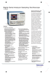
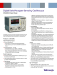
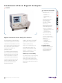
Communications Signal Analyzer
CSA8000
Features & Benefits
Automatic Communication
Measurements
–
–
–
–
–
Q-factor
Extinction Ratio
Optical Power
Signal-to-noise Ratio
Jitter
Wide Bandwidth (DC to
50 GHz with up to
12.5 GHz Trigger)
Automatic ITU/ANSI
Mask Testing
Normal, Infinite, Variable
Persistence and Color
Graded Display Modes
Intuitive User Interface
– Large Color Display (10 in.)
– MS Windows
Operating System
Modular Architecture
Fast Acquisition Rate
Excellent Signal Fidelity
(Jitter <1 ps RMS – Typical)
Digital Communications Analysis Solutions
Specifically designed for high-performance
communications applications, the CSA8000
Communications Signal Analyzer is the ideal
tool for design evaluation and manufacturing
test of datacom and telecom components,
transceiver sub-assemblies and
transmission systems.
The CSA8000 generates measurement
results, not just raw data, with time and
amplitude histograms, mask testing and
statistical measurements. It provides a
communications-tailored measurement
set that includes jitter, noise, duty cycle,
overshoot, undershoot, extinction ratio,
Q-factor, mean optical power and
amplitude measurements.
1
Optical Signal Analysis • www.tektronix.com/optical
FrameScan™
Acquisition Mode
In addition, mask testing of SDH/SONET,
Gigabit Ethernet and other standards
simplifies compliance testing.
– Isolate Data
Dependent Faults
– Examine Low-power
PRBS Signals
A large, full color display helps you to
discriminate waveform details. Colorgrading of waveform data adds a third
dimension – sample density – to your
signal acquisitions and analysis.
Applications
Modularity and Flexibility
The CSA8000 supports a large and growing
family of optical and electrical plug-in
modules. This modular architecture lets
you configure the instrument with the right
features for your application both now and
in the future.
Manufacturing/Testing for
ITU/ANSI Conformance
Designing/Verification
of Telecom and
Datacom Elements
Communications Signal Analyzer
CSA8000
The available optical modules provide complete optical test solutions for both telecom
(622 Mb/s to 40 Gb/s) and datacom (Fibre
Channel and Gigabit Ethernet) applications.
Each optical module includes all of the elements necessary for communications testing;
including an optical to electrical converter, an
average power monitor, one or more reference
receiver filters, a full bandwidth path and a
low-noise electrical sampler. In addition,
clock recovery is available as an option for all
optical modules.
The electrical plug-ins include a variety
of modules with bandwidths up to 50 GHz
and specialized features such as TDR.
High bandwidth probes are also available
for constructing a total acquisition and
measurement solution.
Superior Performance
With its industry-best horizontal stability,
trigger jitter, signal sensitivity and noise
performance, the CSA8000 ensures the
most accurate acquired signal for high-speed
optical communications testing.
The CSA8000’s multi-processor architecture,
with dedicated per channel Digital Signal
Processors (DSP), also provides industrybest waveform acquisition rates that
shorten test times.
The CSA8000’s FrameScan™ acquisition
mode can be used with a variety of BERTs
and/or protocol analyzers to isolate pattern
dependent effects in transmitters or show the
bit sequence leading up to a mask violation.
FrameScan acquisition mode also allows the
averaging of eye diagrams. This can be used
to extract a clean eye diagram from noisy
low-level signals.
2
Optical Signal Analysis • www.tektronix.com/optical
8000 Series Sampling
Oscilloscope Platform
The CSA8000 is built on Tektronix’ new
sampling oscilloscope platform that
combines familiar MS Windows-based PC
technologies with world-class waveform
acquisition technology.
This platform provides a wide array of
standard instrumentation and communications
interfaces (such as GPIB, Parallel Printer Port,
RS-232-C and USB Serial Ports and an
Ethernet LAN connection). In addition,
the platform includes several mass storage
devices (floppy disk, removable hard drive
and CD-ROM).
Finally, because the system supports an open
Windows environment, new levels of
data analysis can be done directly on the
instrument using commercially available
software packages.
Characteristics
Signal Acquisition
Acquisition Modes – Sample (normal), envelope
and average.
Number of Sampling Modules Accommodated –
Up to four, dual-channel electrical and two, singlechannel optical sampling modules.
Number of Simultaneously Acquired Inputs – Eight
channels maximum (eight electrical or two optical and
six electrical).
Vertical Systems
Horizontal System
Main and Magnification View Timebases – 1 ps/div
to 5 ms/div in 1-2-5 sequence or 1 ps increments.
Time Interval Accuracy –
Horizontal sensitivity <21 ps: 1 ps + 1% of interval.
Horizontal sensitivity ≥21 ps:
8 ps + 0.1% of interval (short-term optimized mode).
8 ps + 0.01% of interval (locked to 10 MHz mode).
Horizontal Deskew Range: –500 ps to +100 ns on any
individual channel in 1 ps increments.
Record Length – 20, 50, 100, 500, 1,000, 2,000,
4,000 samples.
Magnification Views – In addition to the main timebase, the CSA8000 supports two magnification views.
These magnifications are independently acquired
using separate timebase settings.
Maximum Trigger Rate – 200 kHz.
Trigger System
Trigger Sources –
External direct trigger.
External pre-scaled trigger.
Internal clock trigger: Internally connected to
direct trigger.
Clock recovery triggers (from optical sampling modules)
– internally connected to pre-scaled trigger.
Trigger Sensitivity –
External direct trigger output:
50 mV, DC –4 GHz (typical).
100 mV, DC –3 GHz (guaranteed).
Pre-selected trigger input:
800 mV, 2 to 3 GHz (guaranteed).
600 mV, 3 to 10 GHz (guaranteed).
1000 mV, 10 to 12, 5 GHz (typical).
Jitter –
Short-term jitter optimized mode:
1.0 ps +5 ppm (typical).
≤1.5 ps +10 ppm (max.).
Locked to 10 MHz reference:
1.6 ps +0.05 ppm of position (typical).
≤2.5 ps +0.1 ppm of position (max.).
Rise Time/Bandwidth – Determined by the sampling
modules used.
Internal Clock – Adjustable from 25 to 200 kHz
(drives TDR, internal clock output and calibrator).
Vertical Resolution – 14 bits over the sampling
modules’ dynamic range.
Trigger Level Range – ±1.0 V.
Trigger Input Range – ±1.5 V.
Trigger Holdoff – Adjustable 5 µs to 100 ms in
2 ns increments.
Communications Signal Analyzer
CSA8000
Display Features
Touchscreen Display – 10.4 in. diagonal, color.
Altitude – Operating: 3,048 m (10,000 ft.);
nonoperating: 12,190 m (40,000 ft.).
M a s k Te s t i n g
Colors – 16,777,216 (24 bits).
Electromagnetic Compatibility – 89/336/EEC.
Video Resolution – 640 horizontal by 480 vertical
displayed pixels.
Standard
Math/Measurement
System Measurements
OC-3/STM-1
155.52
OC-9
466.56
OC-12/STM-4
622.08
OC-18
933.12
The CSA8000 supports up to eight simultaneous
measurements, updated three times per second
with optional display of per measurement statistics
(min, max, mean and standard deviation).
Rate (Mb/s)
OC-1
51.84
OC-24
1244.2
Measurement Set –
Amplitude Measurements: High, Low, Amplitude, Max,
Mid, Min, Peak-to-peak, + Overshoot, – Overshoot,
Mean, Cycle Mean, RMS, Cycle RMS, AC RMS, Gain.
Timing Measurements: Rise, Fall, Period, Frequency,
+ Cross, – Cross, + Width, – Width, + Duty
Cycle, – Duty Cycle, Burst Width, Delay, Phase.
Area Measurements: Area, Cycle Area.
Eye Pattern/Optical Measurements: Extinction Ratio
(Ratio, %, dB), Eye Width, Eye Height, Crossing %, Duty
Cycle Distortion, Jitter (p-p, RMS), Noise (p-p, RMS),
Q-Factor, SNR, Average Optical Power.
OC-36
1866.2
FC-531
531.2
Cursors – Dot, vertical bar and horizontal bar cursors.
FC-1063
1062.5
Waveform Processing
Gigabit Ethernet
1250.0
Up to eight math waveforms can be defined and
displayed using the following math functions: Add,
Subtract, Multiply, Divide, Average, Differentiate,
Exponentiate, Integrate, Natural Log, Log, Magnitude,
Min, Max, Square Root and Filter.
In addition, measurement values can be utilized as
scalars in math waveform definitions.
Mask Testing – In addition to user-defined masks,
the following predefined masks are built-in:
OC-48/STM-16
2488.3
OC-192/STM-64*1
9953.3
OC-768/STM-256
39813.12
FEC 10.66 Gb/s
10664.0
FEC 42.66 Gb/s
42656.0
FC-133
132.81
FC-266
265.6
*1 OC192/STM-64 Mask is per ITU-T, 691 recommendation.
Power Requirements
Line-Voltage Ranges – 90 to 132 VRMS,
180 to 250 VRMS.
Line Frequency – 48 to 440 Hz.
Environmental
Temperature –
Operating: +10°C to +40°C.
Nonoperating: –22°C to +60°C.
Relative Humidity –
Operating: Floppy disk and CD-ROM not installed:
20% to 80% at or below 40°C (upper limit derates
to 45% relative humidity at 40°C).
Nonoperating: 5% to 90% at or below 60°C (upper
limit de-rates to 20% relative humidity at +60°C).
Safety – UL3111-1, CSA1010.1, EN61010-1,
IEC61010-1.
Physical Characteristics
Cabinet
Dimensions
Width
Height
Depth
Weight
Net
Shipping
mm
457
343
419
kg
20.8
36.7
in.
18.0
13.5
16.5
lb.
46
81
Ordering Information
CSA8000
Communications Signal Analyzer.
Includes: User manual, quick reference card,
MS Windows 98 compatible keyboard, MS Windows
98 compatible mouse, WaveStar™ driver, touchscreen
stylus, online help, programmer online guide,
power cord.
CSA8000 Options
Option C3 – Three years of Calibration Service.
Option D1 – Calibration data report.
Option D3 – Three years of calibration data reports.
Option R3 – Extended repair warranty to three years.
Option 1K – Cart.
Option 1R – Rackmount kit (includes: hardware,
tooling and instructions for converting bench model
to rackmount configuration).
International Power Plug
Options
Option A1 – Universal Euro 220 V, 50 Hz.
Option A2 – UK 240 V, 50 Hz.
Option A3 – Australian 240 V, 50 Hz.
Option A5 – Switzerland 220 V, 50 Hz.
Option A99 – No power cord.
Option AC – China 240 V, 50 Hz.
Optical Signal Analysis • www.tektronix.com/optical 3
Communications Signal Analyzer
CSA8000
Contact Tektronix
8000 Series Sampling
Oscilloscope Optical Modules
8000 Series Sampling
Oscilloscope Electrical Modules
ASEAN Countries (65) 356-3900
80C01 Multi-rate Telecom Sampling Module with
Optional Clock Recovery – Supports waveform
compliance testing of long wavelength (1,100 to
1,650 nm) signals at 622, 2,488 and 9,953 Mb/s,
as well as general purpose testing w/up to 20 GHz
optical bandwidth.
80C02 High Performance Telecom Sampling
Module with Optional Clock Recovery –
Supports waveform compliance testing of long wavelength (1,100 to 1,650 nm) signals at 9.953 Gb/s,
as well as general purpose testing w/up to 28 GHz
optical bandwidth.
80C03 Multi-rate, High Sensitivity Datacom
Module with Optional Clock Recovery –
Supports waveform compliance testing of short and
long wavelength (700 to1,650 nm) signals at 1,063,
1,250, 2,488 and 2,500 Mb/s, as well as general
purpose testing w/up to 2.3 GHz optical bandwidth.
80C04 High-performance Telecom Sampling
Module with Optional Forward Error Correction
Clock Recovery – Supports waveform compliance
testing of long wavelength (1100 - 1650 nm)
signals at either 9.953 Gb/s or 10.664 Gb/s as
well as general purpose testing with up to 28 GHz
optical bandwidth.
80C05 40 GHz Multi-rate Telecom Sampling
Module – Supports waveform testing of long
wavelength (1530 - 1580 nm) low-powered telecom
signals at 9.953 Gb/s and 40 Gb/s with selectable
bandwidth settings of 20, 30 and 40 GHz.
80C06 50 GHz Telecom Sampling Module –
Supports waveform testing with the highest optical
bandwidth for communications signal analysis available today of long wavelength (1530 - 1580 nm)
high-powered telecom signals at 40 Gb/s rates and
50 GHz bandwidth.
80E01 – 50 GHz single-channel electrical
sampling module.
80E02 – 12.5 GHz dual-channel, low-noise electrical
sampling module.
80E03 – 20 GHz dual-channel electrical
sampling module.
80E04 – 20 GHz dual-channel electrical sampling
module with TDR.
Australia & New Zealand 61 (2) 9888-0100
Austria, Central Eastern Europe, Greece,
Turkey, Malta & Cyprus +43 2236 8092 0
Belgium +32 (2) 715 89 70
Brazil and South America 55 (11) 3741-8360
Canada 1 (800) 661-5625
Other Accessories
Denmark +45 (44) 850 700
Calibration Step Generator –
Universal Euro: Order 067-1338-01.
UK: Order 067-1338-02.
Australian: Order 067-1338-03.
North American: Order 067-1338-04.
Switzerland: Order 067-1338-05.
Japanese: Order 067-1338-06.
SIU800 Static Isolation Unit – Order SIU800.
Sampling Module Extender Cable (1 meter) –
Order 012-1568-00.
Sampling Module Extender Cable (2 meter) –
Order 012-1569-00.
2X Attenuator (SMA male-to-female) –
Order 015-1001-00.
5X Attenuator (male-to-female) –
Order 015-1002-00.
Power Divider – Order 015-1014-00.
Rackmount – Order 016-1791-00.
P6209 – 4 GHz active FET probe.
P6150 – 9 GHz passive probe.
K4000 Mobile Workstation.
Finland +358 (9) 4783 400
France & North Africa +33 1 69 86 81 81
Germany +49 (221) 94 77 400
Hong Kong (852) 2585-6688
India (91) 80-2275577
Italy +39 (02) 25086 501
Japan (Sony/Tektronix Corporation) 81 (3) 3448-3111
Mexico, Central America & Caribbean 52 (5) 666-6333
The Netherlands +31 23 56 95555
Norway +47 22 07 07 00
People’s Republic of China 86 (10) 6235 1230
Poland (48) 22 251 5340
Republic of Korea 82 (2) 528-5299
South Africa (27 11) 254-8360
Spain & Portugal +34 91 372 6000
Sweden +46 8 477 65 00
Switzerland +41 (41) 729 36 40
Taiwan 886 (2) 2722-9622
United Kingdom & Eire +44 (0)1344 392000
USA 1 (800) 426-2200
For other areas, contact: Tektronix, Inc. at 1 (503) 627-1924
For the most up-to-date product information
visit our web site at www.tektronix.com
Copyright © 2001, Tektronix, Inc. All rights reserved. Tektronix products are
covered by U.S. and foreign patents, issued and pending. Information in this publication supersedes that in all previously published material. Specification and price
change privileges reserved. TEKTRONIX and TEK are registered trademarks of
Tektronix, Inc. All other trade names referenced are the service marks, trademarks
or registered trademarks of their respective companies.
08/01
4
Optical Signal Analysis • www.tektronix.com/optical
HB/XBS
85W-13499-3