1
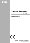
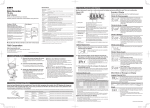
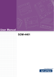
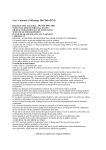
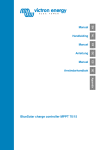
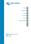
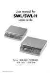
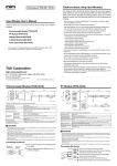
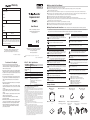
◆ Notices about this User’s Manual
Warranty
Warranty Period
12 months from date of purchase
Customer's name:
Address:
Expansion Unit
Phone No:
Date of Purchase
Dealer's name:
User’s Manual
Address:
Thank you for purchasing our product.
Carefully read this instruction manual
before using this unit.
Phone No:
Object of Repair
Main Unit
Method of Repair
Send in for Repair
● Carefully read and fully understand these instructions before using this unit.
● All rights of this User’s Manual belong to T&D Corporation. It is prohibited to use, duplicate and / or arrange a part or whole of this User’s Manual
without the permission of T&D Corporation.
● Please follow the safety precautions carefully. We cannot gurantee nor are we responsible for safety if this product is used in any manner other than was intended.
● T&D Corporation accepts no responsibility for any malfunction of and / or trouble with this product or with your computer that is caused by the improper handling of this
product and will deem such trouble or malfunction as falling outside the conditions for free repair of the attached warranty.
● Specifications, design and other contents outlined in this manual are subject to change without notice.
● On screen messages, figures or illustrations in this manual may vary slightly or be simplified from the actual messages and product.
● We sincerely hope that the contents of this manual are true and complete. If you find any information to have been omitted, or if the information within is confusing or
mistaken please, contact your retailer or T&D Corporation.
● Company names and product names are trademarks or registered trademarks of each company.
● The warranty that is included in this User’s Manual cannot be reissued, so please keep it in a safe place.
● The User’s Manual for this and all T&D products can be downloaded free of charge from our Web Site.
◆ Safety Precautions and Instructions ※ Please carefully observe the following safety measures when using our product
To prevent any loss or damage to our customers, other people and / or property, and to ensure the proper use of our products we ask that before
using our product you carefully read, understand and follow the safety rules and precautions for our products as outlined below.
DANGER
Do not take apart, repair or modify the main unit. It may cause fire,
electrocution or damage. Ask the shop where you purchased the product
or T&D Corporation to carry out any repairs.
Free repair of the unit will be carried out according to the details laid
down in this manual only if the unit has broken down under normal
usage as outlined in this user’s manual and during the stated warranty
period. Please contact your dealer about repair and present this
document when seeking repair.
If water or a foreign body enters into this unit, immediately remove the
batteries and stop using. Continued use may cause fire or electrocution.
Store all batteries, sensors and Thermo Recorder units out of the reach
of children. It is dangerous to swallow batteries.
If any smoke or strange smells are emitted from the unit, immediately
cease using it. Continued use may cause fire, electrocution.
Please be careful when you using in overly hot or cold environments,
touching the units may cause burns or frostbite.
Do not use any batteries other than AA Alkaline battery.
It may cause fire or damage.
Shimadachi 817-1, Matsumoto, Nagano 390-0852 Japan
Tel (+81)263-40-0131 Facsimile (+81)263-40-3152
Office Hours : Monday to Friday 9:00-12:00 / 13:00-17:00
This is printed on recycled paper
Shimadachi 817-1, Matsumoto, Nagano 390-0852 Japan
Tel (+81)263-40-0131 Facsimile (+81)263-40-3152
HP : http://www.tandd.com/
E-mail : [email protected]
��������������������������� �������������������������� ����
2009.04 16004224640 3rd Edition
Provisions for Free Repair
1. If the unit does not work properly despite the fact that the
customer used it properly and in line with the User's Manual, the
unit shall be repaired free of charge through the distributor from
which the unit was purchased.
2. If the customer requests free repair because of trouble within the
warranty period, bring or send the unit along with the warranty to
the dealer. A service charge may be added if a repairperson must
be sent out to the place of use for repair.
3. If you have moved after purchasing, or the product was received
as a gift, or there are some difficulties contacting the shop from
which you purchased the unit, please contact us directly for
service.
4. Free repair is not available in the following cases even though it is
within the warranty period:
1. Trouble or damage was caused by careless operation, natural
disaster, fire, public pollution, or use of a power source other than
specified.
2. If repair, adjustment, disassembly or modification of the unit
has been carried out by a person other than a T&D authorized
engineer.
3.Trouble or damage was caused by transportation, movement or
dropping of the unit after purchase.
4.Failure to submit the Warranty or failure to fill in all items
required in the Warranty.
5. The Warranty cannot be reissued.This Warranty only promises
customers free repair within the period and conditions clarified in
this Warranty. Therefore, the customer's legal rights will not be
limited by this Warranty. For further information on repair and
other service questions after the termination of the warranty
period, contact your dealer.
VR-00P1 Basic Specifications
Device Name
Compatible Devices
VR-00P1
Voltage Recorder VR-71
Preheat Output
Terminal Contact
Capacity
DC30V 100mA ON Resistance:MAX15 Ω
Battery
Dimensions
Weight
Accesories Included
in Package
AA Alkaline Battery (LR6) x 1
H57mm × W95mm × D24mm(excluding protrusions)
230g (including one AA battery)
AA Alkaline Battery (LR6) x 1
Wall Attachment Unit (TR-00K2) x 1
Connection Cables x 2 [VR-1C01 (15cm) x1 and
VR-1C10 (1m) x 1]
User's Manual (Warranty) x 1
※ This device is not waterproof.
*FCC Compliance Statement for American Users
This device complies with Part 15 of the FCC Rules.
Operation is subject to following two conditions: (1) this device may not cause harmful interference.
and (2) this device must accept any interference received, including interference that may cause
undesired operation.
NOTE: This equipment has been tested and found to comply with the limits for a Class A Digital
Device, pursuant to Part 15 of the FCC Rules. These limits are designed to provide reasonable
protection against harmful interference in a residential installation. This equipment generates, uses
and can radiate radio frequency energy and, if not installed and used in accordance with the
instructions, may cause harmful interference to radio communications.
However, there is no guarantee that interference will not occur in a particular installation. If this
equipment does cause harmful interference to radio or television reception, which can be
determined by turning the equipment off and on, the user is encouraged to try to correct the
interference by one or more of the following measures:
-- Reorient or relocate the receiving antenna.
-- Increase the separation between the equipment and receiver.
-- Connect the equipment into an outlet on a circuit different from that to which the receiver is
connected.
-- Consult the dealer or an experienced radio/TV technician for help.
Warning : This equipment has been verified to comply with the limits for a Class A personal digital
device, pursuant to Subpart B of Part 15 of FCC Rules. Only peripherals (computer input/
output devices, terminals, printers, etc.) certified or verified to comply with the Class A or
B limits may be attached to this equipment. Operation with non-certified or non-verified
personal computer and/or peripherals is likely to result in interference to radio and TV
reception. The connection of a non-shielded equipment interface cable to this equipment
will invalidate the FCC Certification of this device and may cause interference levels
which exceed the limits established by the FCC for this equipment.You are cautioned that
changes or modifications not expressly approved by party responsible for compliance
could void your authority to operate the equipment.
Distributed by MicroDAQ.com, Ltd.
CAUTION
We are not responsible for any malfunction or trouble caused by the use
of our product or by any problem caused by the malfunction of our unit.
Please be fully aware of this before using our product.
This unit is only to be used by connecting it to a Voltage Recorder.
Do not use it for any other purpose than it was designed for.
Operate the units with the latest version of [Voltage Recorder for
Windows®]. The latest version software can be downloaded from our
home page.
This product has been designed for private or industrial use only. It is not
for use in situations where strict safety precautions are necessary such
as in connection with medical equipment whether directly or indirectly.
Do not use the Expansion Unit connection cable to connect to any other
device other than the Voltage Recorder. Before disconnecting the cable,
make sure to first stop recording and then disconnect. This may cause
damage including malfunction.
Do not drop the unit, or expose the unit to a strong impact. If that
happenens to the unit, immediately remove the batteries and stop using.
Continued use may cause fire or electrocution.
Condensation may occur if the unit is moved from one environment to
another where the difference in temperature is great. Use the unit in an
enenvironment where the ambient temperature is from 0 to 50℃ and the
humidity is from 90%RH (no condensation) or less.
Pre-heat output terminal has polarity (+ / -). Do not make a mistake with
the polarities when wiring.
Preheat Output Capacity: up to DC30V 100mA
Do not connect it to anything that exceeds this specified range.
Battery terminals may provide insufficient contact due to age or vibration.
Please be careful not to lose data due to insufficient contact.
Do not use or store the unit in places such as listed below:
It may cause electrocution, fire or damage to the unit or to your computer
● Areas exposed to direct sunlight
● Areas exposed to water or high-pressure water flow
● Areas exposed to organic solvents and corrosive gas
● Areas exposed to strong magnetic fields
● Areas exposed to static electricity
● Areas near fire or exposed to excessive heat
● Areas prone to smoke, dust and dirt
Battery life depends on the measurement environment, communication
frequency, recording interval and battery quality.
Remove batteries from any unit that will not be used for a long period of
time. Batteries left in a unit not being used for a long time may leak and
cause a malfunction.
Package Contents
■ Expansion Unit VR-00P1 x 1
■ User's Manual (Warranty)
x1
■ AA Alkaline Battery x 1
■ Connection Cable
VR-1C01 (15cm) x 1
■ Wall Attachment Unit
Example of Installation using Wall Attachment
(TR-00K2 with 1 seal included)
x1
① Set the VR-71 into the
wall attachment
www.MicroDAQ.com
(603) 746-5524
■ Connection Cable
VR-1C10 (1m) x 1
② Put the seal on the back
of the wall attachment.
③ Attach to the expansion unit.
Inserting the battery
Outline of the Expansion Unit
This expansion unit includes functions that allow you to transmit a preheat signal to sensors and also allows you to simultaneously record with up to 4
VR-71 units.
When using for the first time, insert the battery as follows.Please use the following as a rough outline for when to use the [Check] button to check
the battery.
◆ Expected
* The preheat function transmits a preheat signal that is synchronized with the VR-71 recording timing to turn sensors or other devices ON and
OFF. The output timing of the ON / OFF signal can be set into the voltage recorder via your computer.
* The simultaneous recording function allows you to simultaneously record with up to 4 VR-71 units. After having made settings via your computer
to assign one of the voltage loggers as a Master Unit and the others as Slave Unit(s), connect all the loggers to the Expansion Unit. The Slave
Unit(s) will receive an output signal from the Master Unit that will call for the Slave(s) to measure / record at the same time as the Master.
Battery Life
◆ Expected
The Expansion Unit can have 1 Master and up to 3 Slave Units connected.
【FRONT】
【RIGHT SIDE】
① The Check LED will light up in the following situations.
1.When pressing the Check button (Manual output of pre-heat signal /
Checking Battery power)
2.When the preheat signal output is ON.
3.When the simultaneous recording timing is synchronized.
② Check Button
③ Slave cable connector jacks
④ Pre-heat output terminal
⑤ Master cable connector jack
At a recording interval
of over 10 minutes
At a recording
interval if 1 minute
About 1 year
About 2 months
battery life when using the simultaneous recording function
Battery Life
Part Names
【LEFT SIDE】
battery life when using the preheat function
At a recording interval
of over 1 minute
At a recording
interval of 1
second
At a recording
interval of 20 msec
About 1 year
About 2 months
About 7 days
NOTE:
・Battery life will depend on the recording environment, recording interval, communication frequency, and ambient temperature. The above
batterylife test was carried out using brand new batteries and in no way do we guarantee a battery's life.
・When using the expansion unit for simultaneous recording and the battery power is lost, the Slave will no longer be able to get the recording
signal from the Master and although the REC mark is on, recording will have been stopped. If this occurs, the data consistency may be lost.
【How to change the battery】
WARNING:The unit can only remain operating for up to 1 minute without a battery. Please replace the battery within that time.
① Loosen the 4 screws on the side and open
the case. Be careful when opening the case,
it may be fastened on a bit tight.
② Insert the battery making sure to align +/-
correctly.
③ Close the case and tighten the
screws.
Screw
How to Use
1. Making
Operational Settings
2. Connect
Settings can be made via the software [Voltage Recorder for Windows].
【Simultaneous Recording Function Settings】
① Check to make sure that the power of the main unit is ON. Settings can be made for 1 Master and up to 3 Slave Units for that Master.
→ For details, see the [Voltage Recorder User's Manual].
1.Master Unit Settings
② Using the provided communication cable, connect the VR-71 Voltage
① Connect the Voltage Recorder to your computer and make the normal
Recorder to your computer's serial port. operational settings. For details, see the [Help] Menu in the software.
→ For details, see the [Help] Menu in the software.
③ From the [Communication] Menu, select [Recording Start].
② With the Expansion Unit Settings, check the various items as listed
④ The Recording Start window will appear where you can make all
below. If using the pre-heat function, make sure to check Pre-heat.
necessary settings concerning recording.
1.Connect the Voltage Recorder and sensors to the Expansion Unit.
・Both the pre-heat function and the simultaneous recording function
will work at the same time.
【Example of a Pre-heat Connection】
��������
�������������������������
������������
By pressing the CHECK button
you can manually turn the
pre-heat output signal to ON
without having to deal with the
Voltage Recorder. Activated as
long as you are pressing.
③ By clicking the [Send Settings] button, the settings will be completed.
If you have selected a programmed recording start, by clicking the
[Send] button the unit will be put into recording waiting status.
Expansion Unit Settings
【Pre-heat Function Settings】
① Make all normal operation settings necessary to use the voltage
recorder.
→ For details, see the [Help] Menu in the software.
・When using the simultaneous recording function, make sure to not
mistake with the connection of the Master and Slave Units; a mistake
will cause the units to not operate properly.
・While using the simultaneous recording function do not disconnect
the connection cable from the Expansion Unit. If this occurs, the data
consistency may be lost. If you wish to disconnect the cable, stop
recording from the Master before disconnecting.
By pressing in on the REC button for more than 2 seconds the REC mark
< Front of Expansion Unit >
【Example of a Simultaneous Recording Connection】
① Connect the Voltage Recorder to your computer and in the Expansion
Unit Settings, check the various items as listed below.
will appear in the LCD and recording will start.
・When using the simultaneous recording function, only the Master
buttons will be active. By pressing in on the [REC /STOP] button on
the Master Unit, the Slave Unit(s) will also start or stop recording
accordingly.
・When using the Expansion Unit, the Voltage Recorder’s LCD will
show「----」before starting a recording and after a recording
session has been started will change to show the value of the previous
measurement.
② With the Expansion Unit Settings, check the various items as listed
below and set the pre-heat time or how many seconds beforehand
you wish the power to be turned ON.
③ By clicking the [Send Settings] button, the settings will be completed.
If you have selected a programmed recording start, by clicking the
[Send] button the unit will be put into recording waiting status.
・Pre-heat output terminal has polarity (+ / -). Make sure to properly
align when wiring.
3. Recording Start
NOTE:
When making settings for the date and time to start a recording under
a programmed start, make sure to take into account times when the
voltage recorder and sensor will be connected.
2.Slave Settings
◆ Manual output of
pre-heat signal
NOTE:
・By removing the Expansion Unit from a Voltage Recorder while using
the pre-heat function, the output signal to the sensor will be turned
OFF and the recording of data will become deactivated.
NOTE: For our Customers using Data Collector TR-57U and/or RTR-57U
② Make the basic operational settings. For details, see the [Help] Menu
in the software.
③ By clicking the [Send Settings] button, the settings will be completed.
If you are using a multiple number of units, repeat steps ①~③ .
Although VR-71 may be set up by the user as Master and Slave, when using Data
Collectors TR/RTR-57U to download recorded data, the Data Collector will not be able to
recognize the Master / Slave relationship.Please carry out the following operations.
If you wish to use VR-71 units in a “Master / Slave” relationship and use a Data Collector
TR/RTR57U to collect recorded data from these units, before starting a recording
If at the same time you wish to use the simultaneous recording function,
Slave Unit
continue by making the necessary settings in the [Simultaneous Recording
Function Settings]. The pre-heat function settings cannot be made via a Slave
Unit; they must be made with the Master Unit.
Master Unit
session please set the recording interval of “Slave” units to the same as that of the
“Master”
unit. After downloading “slave” data from a Data Collector TR/RTR-57U,
please use the software to make sure to set the Recording Start time for the “Slave(s)” to
the same as that of the “Master”.
Distributed by MicroDAQ.com, Ltd.
www.MicroDAQ.com
(603) 746-5524