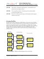
1
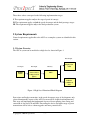
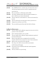
October 23, 2009
Dr. John S. Bird
School of Engineering Science,
Simon Fraser University,
Burnaby, BC, V5A 1S6
Re: ENSC 440 Functional Specifications for Auto-Splice Conductivity Analyzer
Dear Dr. Bird:
The enclosed document from Prospect1 Inc. outlines functional specification for the
Auto-Splice Conductivity Analyzer (ASCA). The aim of this project is to design a device
that uses Hall Effect Sensors to calculate magnetic field intensity in splices in overhead
transmission lines. It can then be used to analyze the imbalance of current in strands of an
ACSR (Aluminum Conductor Steel Reinforced) overhead wire. Attached LEDs and LCD
display on the device will help the user identify the extent of damage present in the
splice.
The functional specifications mentioned in this document provide a set of high-level
standards and requirements for the ASCA device’s functionality for both the proof-ofconcept and product phases. The management team along with test and design engineers
will make use of this document in research and development activities.
Prospect1 Inc. consists of four enthusiastic and hard working fourth year Engineering
Science students: Amir Najafzadeh, Sam Hoque, Milad Moezzie and Zhouhao Cui. We
are very excited about the opportunity this project may hold in lessening the failure rates
of automatic splices in overhead distribution systems. Please feel welcome to contact us
if you have any questions or concerns by phone at (778) 229-9190 or by e-mail at
[email protected]
Sincerely yours,
Amir NajafZadeh
CEO Prospect1 Inc.
Enclosure: Functional Specifications for Auto-Splice Conductivity Analyzer
Copyright ©, 2009 Prospect1 Inc.
-1-
Functional Specifications for
Auto-Splice Conductivity Analyzer
Project Team:
Amir Najafzadeh
Sam Hoque
Mlad Moezzie
Zhouhao Cui
Contact Person:
Amir Najafzadeh
[email protected]
Submitted to:
Dr. John Bird
Steve Whitmore
Jason Lee
School of Engineering Science
Simon Fraser University
Issued date:
October 23, 2009
Revision:
1.3
Copyright ©, 2009 Prospect1 Inc.
-2-
Executive Summary
Overhead transmission cables are a standard mean of distributing electricity to homes.
The wires in a transmission line are connected with one another via metal clamps referred
to as automatic splices or auto-splices. There is a growing concern over the failure rate of
these auto-splices due to corrosion. This limits conductivity and also lessens the current
passage area throughout the wire. An overhead wire in such a condition may eventually
break and the live wire may fall on the ground. In addition to loss of power and electricity
transmission, this introduces risk of electrocution and fire [1]! A live cable on the ground
is a serious safety concern. Currently there is no specific solution for this splice issue.
Prospect1 Inc. has come up with an idea and a technology to overcome this safety issue.
As splices age, Aluminum components oxidize to form an insulating barrier thereby
increasing their resistance and causing a current imbalance in cables’ strands [2]. We
concentrated our effort on the study of this current imbalance and the resulting magnetic
field around the cables’ strands and came up with ASCA – a device that uses Hall Effect
Sensors to measure this change in magnetic field intensity to monitor failure in splices.
Development of the ASCA device is divided in to two phases. Upon completion of the
first phase, the device will be able to obtain data regarding magnetic field intensity
around live wire utilizing the Hall Effect Sensors and store them at the MCU.
In the second phase, this data will then be displayed on the LCD along with an LED
indicator. During this phase, the casing of the device will also be prepared and the
product will reach completion.
This document presents the functional specifications of the ASCA device. The main
focus here is to outline the functional specifications of the proof of concept prototype for
ASCA. This document also mentions some future functionality that can possibility be
added to the final commercial product as an upgrade later.
.
Copyright ©, 2009 Prospect1 Inc.
-3-
Table of Contents
Executive Summary........................................................................................ 3
List of Figures ................................................................................................. 5
Glossary .......................................................................................................... 5
1. Introduction................................................................................................. 6
1.1 Scope ..................................................................................................... 6
1.2 Intended Audience................................................................................. 6
1.3 Classification ......................................................................................... 6
2 System Requirements .................................................................................. 7
2.1 System Overview .................................................................................. 7
2.2 General Requirements ........................................................................... 8
2.3 Physical Requirements .......................................................................... 8
2.4 Electrical Requirements ........................................................................ 9
2.5 Mechanical Requirements ................................................................... 10
2.6 Environmental Requirements.............................................................. 10
2.7 Standards ............................................................................................. 10
2.8 Reliability and Durability.................................................................... 11
2.9 Safety Requirements............................................................................ 11
2.10 Performance Requirements ............................................................... 11
2.11 Usability Requirements ..................................................................... 12
3 User Documentation .................................................................................. 12
4 System Test Plan........................................................................................ 13
5 Conclusion ................................................................................................. 14
6 References.................................................................................................. 15
Copyright ©, 2009 Prospect1 Inc.
-4-
List of Figures
Figure 1: High-Level Functional Block Diagram...........................................7
Figure 2: High-Level Block Diagram for System Test Plan.........................13
Glossary
ASCA
Auto-Splice Conductivity Analyzer
LCD
Liquid Crystal Display
LED
Light Emitting Diode
MCU
Arduino Duemilanove Micro Controller
User
Certified Technicians/Electricians who are authorized to
perform maintenance and testing on overhead
transmission lines
Hot Stick
An insulated rod usually made of fiber glass. It can be of
extendable length [3]
ANSI
American National Standards Institute
CGSB
Canadian General Standards Board
CSA
Canadian Standards Association
NERC
North American Electric Reliability Corporation
IEC
International Electrotechnical Commission
RoHS
Restriction of the Use of Certain Hazardous Substances
in Electrical and Electronic Equipment Regulations
MTBF
Mean time between failures
Copyright ©, 2009 Prospect1 Inc.
-5-
1. Introduction
Auto-Splice Conductivity Analyzer (ASCA) is designed to determine current imbalance
in overhead transmission line cables. From the resulting magnetic field around the cables’
strands, this imbalance can be found, and used to verify if the splice is faulty. The device
has an LCD on it, which shows the intensity of the magnetic field around the splice.
There are also a couple of LEDs on the device, which lets the user know if the intensity
of the magnetic field is within range or out of range. ASCA can be attached to the wire as
a slide-on device to obtain data. The requirements for the ASCA device, as proposed by
Prospect1 Inc. are described in this functional specification.
1.1 Scope
This document lists all the functional requirements that must be met by a functional
ASCA. These listed requirements will guide various design phases later. It also serves as
a basis for Design Specification later.
1.2 Intended Audience
The document is intended for the use of all Prospect1 Inc. members. It will also serve as a
tool to the project manager who shall use it to evaluate progress throughout the different
development phases. It will also serve as a guide to him to comply with necessary
manufacturing and usability standards. Design engineers shall follow this document to
meet overall design requirements from production to implementation of device. Test
engineers shall use this document to assess the match in functionality between the actual
device and the guidelines outlined here. Marketing department may also use this
document to develop marketing materials and identify similarities in features (if any)
with competitor’s products.
1.3 Classification
Throughout this document, the following convention shall be used to denote functional
requirements:
[FSn-p] <“A functional requirement”>
This format of representation is compatible with the CSA requirements of referencing.
Here, n is the functional requirement reference number and p is the priority of the
functional requirement denoted by one of the three values: I, II or III. [5]
Copyright ©, 2009 Prospect1 Inc.
-6-
These three values correspond to the following implementation stages:
I. The requirement applies only to the stage of proof-of-concept.
II. The requirement applies to both the proof-of-concept and the final prototype stages.
III. The requirement applies only to the final production system.
2 System Requirements
General requirements applicable to the ASCA as a complete system are identified in this
section.
2.1 System Overview
The ASCA system can be modeled at a high-level as shown in Figure 1.
Data Output
User Input
Data Input
On/Off
Switch
Hall Effect
Sensors detect
voltage level in
Splices
Memory
Data is
displayed on
LCD
Data is stored in
MCU
LED
indicates
condition of
data
Figure 1: High-Level Functional Block Diagram
Due to time and budget constraints, in the proof-of-concept stage of development, only
selected functionality aspects of the ASCA system will be designed and implemented.
This stage will implement the fundamental aspects of data capturing, data storing and
extraction of data via LCD and LED. Fine tuning the device for higher range of power
transmission will be left as a future upgrade and more potential sales.
Copyright ©, 2009 Prospect1 Inc.
-7-
The device is turned on by pushing the ‘On/Off’ switch by the user. Once turned on, it
will be attached to a hot stick and elevated to a height in line with the splice on a
transmission wire. Then the device will be put on the splice through the opening and slid
along its length. At this time, raw data will be captured by the two Hall Effect sensors [4]
and recorded in the memory. Attempt is made to have the sensors located close enough to
the wire within mechanical constraints. This will assure significant reduction in noise
signal as well as accurate data accumulation. The data is then stored, in small blocks, in a
buffer in the Processor Memory. The user then uses the hot stick to bring the ASCA
device down. Once it is back in hand, the user presses the ‘View Data’ button to observe
captured data. This is when stored data is displayed on the LCD along with an LED
indicator. There are three LEDs on the device and they represent the following:
- Green LED: Data is within optimal range
- Red LED: Data is out of range
- Blue LED: Data is irrelevant or there is insufficient data
2.2 General Requirements
[FS1-II]
The ASCA device shall have an idle state in which no data is captured or
displayed on the LCD. This idle state is when the device is turned off
[FS2-II]
The system shall activate when the ‘On/Off’ switch is turned ‘On’
[FS3-II]
Sensors and connection wires shall be minimally intrusive to the user
[FS4-III]
The internal construction of the device shall be modular, allowing for
substitution/addition of features in future models
[FS5-III]
The device must be mountable onto a hot stick
[FS6-II]
The device shall be battery powered
[FS7-III]
The suggested retail price of the device shall be under CDN$300
2.3 Physical Requirements
[FS8-III]
The device shall be fabricated with a hard cover box to protect the
components and electronics from possible damage
[FS9-III]
The hard cover protection shall be made of durable plastic material which
has some degree of heat resistance
Copyright ©, 2009 Prospect1 Inc.
-8-
[FS10-II]
Due to Hall Effect Sensor’s sensitivity range, the distance between the 2
walls (the inner diameter) where the sensors are mounted must not be
greater than 3cm
[FS11-II]
The system shall have an LCD display and three LEDs
[FS12-III]
The switches and buttons shall be placed reasonably and intuitively, so
that it is difficult to press buttons unintentionally
[FS13-III]
The device must have a hook attached to it, so that it can be mounted by a
hot stick
[FS14-III]
The device shall not have any sharp edges in order to protect the user
[FS15-III]
Weight of device shall not exceed 1.0 kg
[FS16-III]
The system shall be protected from small static shocks and bumps
2.4 Electrical Requirements
[FS17-II]
The power supply shall be sufficient to support necessary power needed to
operate the sensors and the MCU
[FS18-II]
Power consumption shall be as low as possible
[FS19-II]
The power supply shall be sufficient to support simultaneous operation of
the entire internal circuitry
[FS20-II]
Batteries along with the power consumption of the circuit shall be
designed so that the device can operate for at least 14 hours continuously
[FS21-III]
Batteries in the system shall be easily replaceable
[FS22-I]
Key voltage nodes shall be easily accessible for measurement,
troubleshooting and debugging
[FS23-III]
Device may be used in conjunction with other electrical equipments
without interference
[FS24-III]
The device will have no exposed wiring
Copyright ©, 2009 Prospect1 Inc.
-9-
2.5 Mechanical Requirements
[FS25-III]
The mechanical components of the ASCA device shall not be visually or
physically obtrusive
[FS26-III]
The device casing shall be durable and robust to withstand repetitive
rigorous outdoor use
[FS27-III]
User interface shall include clearly marked pushbuttons
2.6 Environmental Requirements
[FS28-III]
The analyzer shall operate normally within an elevation range from sea
level to 2000 meter above sea level
[FS29-III]
The device shall operate between temperatures of - 40 degrees Celsius to
80 degrees Celsius
[FS30-III]
The device shall operate between 0% to 60% relative humidity
[FS31-III]
Operational environment is an outdoor overhead transmission wire line
[FS32-II]
The system will produce virtually no noise while active or inactive
[FS33-II]
Noise produced during operation will be minimized and below 50dB
[FS34-I]
All components will be connected to the main device with silver solder as
opposed to traditional tin/lead type of solder
[FS35-II]
Vibration will not adversely effect the operation of the device
2.7 Standards
[FS36-III]
The device shall conform to CGSB-44.232-2002 standards [9]
[FS37-III]
The device shall conform to ANSI standards
[FS38-III]
The device shall meet CSA requirement CSA-ISO 9241-5-00 [10]
[FS39-III]
The device shall conform to IEC 62369-1 standards
[FS40-III]
The device shall meet NERC standards
[FS41-III]
All components of the device shall be RoHS compliant
Copyright ©, 2009 Prospect1 Inc.
- 10 -
2.8 Reliability and Durability
[FS42-III]
The device shall be durable enough to withstand day-to-day physical
treatment and harsh environment
[FS43-III]
The device shall be serviceable by trained technicians
[FS44-III]
Regular service intervals shall be at least yearly
[FS45-III]
The user interface shall be resistant to breakage under normal operating
conditions
[FS46-III]
The MTBF of the chair shall be no less than 20,000 hours
[FS47-III]
System performance shall not degrade from normal use
[FS48-III]
The system will have a lifespan of at least 3 years of normal use
2.9 Safety Requirements
[FS49-III]
The device shall be covered with a smooth insulating layer, thus it would
not cause bodily harm to user
[FS50-III]
The electronic and mechanical components along with the power
connections shall remain in an enclosure
[FS51-II]
It shall not cause fire hazard in case of malfunction
[FS52-II]
The device shall not spontaneously combust
[FS53-III]
The display and user interface shall not be a strain to the eyes of users
[FS54-II]
Signal emissions from the device shall not interfere with other electronics
[FS55-II]
The system should not provide any static shock when touched
2.10 Performance Requirements
[FS56-III]
The manual On/Off button on the device shall respond to the user
instantaneous
[FS57-III]
The device shall retrieve data from the splice 10 times every second
[FS58-III]
The device shall return the result of the condition of the splice within 1ms
Copyright ©, 2009 Prospect1 Inc.
- 11 -
[FS59-II]
The total time taken for data retrieval and data analysis and display of the
result is less than 2 seconds
[FS60-II]
Data Storage unit shall be accessible by the microcontroller or other
memory reading devices at all times
[FS61-III]
Size of Data Storage unit shall be sufficient for at least 14 hours of normal
operation
2.11 Usability Requirements
[FS62-II]
The device shall reset itself after it is turned on
[FS63-III]
The device shall have an interface for external connection with a PC for
diagnostic purposes
[FS64-III]
Device shall be pre-configured with necessary adjustments and technical
setups before delivering it to the end user
[FS65-III]
The device shall have clear and proper labeling
[FS66-III]
The system shall be intuitive to use
[FS67-III]
The device firmware shall be upgradeable by a service person
3 User Documentation
[FS68-III]
User documentation shall include a website with general and technical
support information
[FS69-III]
A user manual may be written in different languages including English.
The user manual shall be written for users with minimal knowledge
[FS70-III]
A detailed installation guide for technicians and vendors shall be created
[FS71-III]
Both the user manual and the installation guide will be available on the
company website
[FS72-III]
A detailed list of parts used for the device shall be created
Copyright ©, 2009 Prospect1 Inc.
- 12 -
[FS73-III]
There will be a ‘Frequently Asked Questions’ section both in the user
manual and on the company website
[FS74-III]
To ensure quality assurance, a detailed copy of the warranty shall be
provided along with the device
[FS75-III]
Prosect1 Inc. shall also provide copies of all documents on the company
website for easy access
4 System Test Plan
In order for the system to function in a reliable manner, it is necessary to test it during
different stages of design and implementation, prototype building and manufacturing. To
avoid errors, the general test plan is to test each module as it is built, and to retest the
modules upon integration into the complete unit. From designing this device to building a
prototype, the tests associated with various stages can be divided in to three main
categories. For this project, they will be named as unit testing, constituent testing and
prototype testing.
Unit Testing
Test
Individual
Module
Test
Individual
Module
Constituent Testing
Test Integrated
Module of
System
Test Integrated
Module of
System
Test
Individual
Module
Test
Individual
Module
Prototype Testing
Test Integrated
Module of
System
Complete
System Test by
Designer
Complete
System Test by
Potential User
Figure 2: High-Level Block Diagram for System Test Plan
Copyright ©, 2009 Prospect1 Inc.
- 13 -
Unit testing refers to the test of each and every unit and element in the design. This is
done on both the hardware and software segments. These tests ensure that the design and
internal components are functioning in a desired manner. Also, at this stage of
testing, boundary conditions are taken into consideration. This can assure a hassle free
integration later on.
Constituent testing is the second step in system testing. At this stage the design gets
divided into smaller building blocks. For example, one such small block may be the
display of output data through the combination of LCD and LED. Depending on the data
stored at the MCU, the output signal will show a specific display on the LCD and
accordingly an LED light will flash. Other such blocks that may need testing can include;
- obtaining differential data through the Hall Effect sensors,
- storing data at MCU
- extracting data from MCU, etc.
At this stage, a general overview of unit testing of each component may be reviewed
again. This can help eliminate potential errors that may arise at this stage of testing.
The last step in the system test plan is prototype testing. After the smaller blocks pass
constituent testing, they are ready for integration. Once integrated, prototype testing can
make sure that the smaller blocks put together are functioning well and are in cohesion.
At this stage, boundary conditions shall be tested in greater details again. This may give
the designers an idea on how well the functionality of the device in different conditions
matches its functional specifications. It may also be a good idea to have potential users
try the prototype before commercialization or mass production of this device is done.
Their feedback may point to any negativity in the device or lead to possible upgrades and
improvements for future.
If at any point of the building process a change in either design or raw material was
found necessary, the system shall be tested again from the stage where changes were
needed.
5 Conclusion
The functional specifications clearly outline the capabilities, features and requirements of
the Auto-Splice Conductivity Analyzer (ASCA) device. Development of a final prototype
device shall take place in two distinct phases, both of which are proceeding in parallel.
Work has already begun and it is expected that the above mentioned functional
requirements that applies to the proof-of-concept model (marked with I or II) will be
completed by the target date of December 2009.
Copyright ©, 2009 Prospect1 Inc.
- 14 -
6 References
[1] Transmission & Distribution World, “Forensic Analysis of Automatic Splices Leads
to Change”, http://tdworld.com/mag/power_forensic_analysis_automatic
[2] Ensuring the Health of Our Power Lines, “Power line and connector splice sensor”,
http://www.swri.org/3PUBS/ttoday/Summer06/PoweLines.htm
[3] TEL-O-POLE II Parts List, Hastings,
http://www.westernsafety.com/Hastings/hastingspg1.html
[4] Busse, G., Hemelrijck, D., Solodov, I., Anastasopoulos, A., Emerging Technologies
in NDT, “How Infrared has been used in the past”, pg 304-310
[5] Engineering Science 305/440, http://www.ensc.sfu.ca/~whitmore/courses/ensc305
Copyright ©, 2009 Prospect1 Inc.
- 15 -