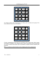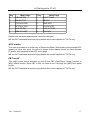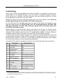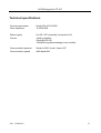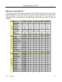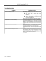
1
IK1ZYW Keypad for FT-817
IK1ZYW KEYPAD
for FT-817(ND)
User's Manual
An IK1ZYW creation.
All rights reserved.
Doc. v.20090418
1
IK1ZYW Keypad for FT-817
Table of Contents
What is it?.............................................................................................................................................3
Special thanks.......................................................................................................................................4
Disclaimer.............................................................................................................................................5
Quick start............................................................................................................................................6
Tested on...............................................................................................................................................7
How it works........................................................................................................................................8
Radio setup......................................................................................................................................8
Main Menu.......................................................................................................................................8
Main functions....................................................................................................................................10
Direct frequency dial.....................................................................................................................10
Frequency presets..........................................................................................................................10
Onboard memories.........................................................................................................................10
Mode change..................................................................................................................................11
VFO toggle....................................................................................................................................12
Split toggle.....................................................................................................................................12
Lock on/off....................................................................................................................................12
Quick tune......................................................................................................................................12
Manual tune...................................................................................................................................12
Timed tuning..................................................................................................................................13
Lazy PTT.......................................................................................................................................13
RIT on/off......................................................................................................................................13
Repeater offset direction................................................................................................................14
Extra FT-817(ND) functions..............................................................................................................15
VOX toggle....................................................................................................................................15
Meter functions..............................................................................................................................15
Power level....................................................................................................................................15
Break-in toggle..............................................................................................................................16
Scan up/down/stop.........................................................................................................................16
Menu Quick Jump..........................................................................................................................16
AGC modes....................................................................................................................................17
PBT on/off.....................................................................................................................................17
Customizing........................................................................................................................................18
Support...............................................................................................................................................20
Technical specifications......................................................................................................................21
What you would get if........................................................................................................................22
Troubleshooting..................................................................................................................................23
Microcontroller programming............................................................................................................24
Assembling.........................................................................................................................................25
Connections........................................................................................................................................27
To Keypad......................................................................................................................................27
To FT-817.......................................................................................................................................28
Cheat sheet..........................................................................................................................................29
Doc. v.20090418
2
IK1ZYW Keypad for FT-817
What is it?
The IK1ZYW Keypad for FT-817 is a wired partial remote control for the little Yaesu
transceiver. It was conceived during a 6-hour field session at 2700 m.a.s.l. for a VHF
contest in August 2008. Three functions were accessed very often, always hunting for
them through the menu: power level, meter mode and VOX toggle. Some easily accessible
presets would have helped quick QSYs to special band spots too.
A search on Internet returned few keypads for the little 817, but none that would “export”
my three most needed functions. So this project was born.
First a microcontroller had to be selected. Atmel line was chosen because their chips can
be programmed with high level languages (C and even BASIC!) and are cheap. Then I
built the simple development hardware and started to get acquantained with the μC
architecture (last I programmed was Zilog's Z80): LED blink, send VFO toggle, send
frequency information, interact with the radio.
It took 3 months of after-dinner development to produce the first version of a fully
functional FT-817 accessory. But work is still going on...
Until proven wrong, this keypad works on all series of FT-817 and FT-817ND.
What is it NOT? This keypad is not a replacement of any computer-based control
software. This keypad is not designed to work with all Yaesu radioes, altought basic
functions should be portable to FT-857's and FT-897's: direct dial, VFO toggle, on-board
presets and mode change. This keypad is not designed for use in any environment or use
case that involves direct or indirect emergency traffic handling and/or life support activities.
Doc. v.20090418
3
IK1ZYW Keypad for FT-817
Special thanks
This project has been made possible thanks to, in chronological order:
●
my Parents that bought me an experimenter's book when I was 10 and supported
me in my studies, hobbies and choices
●
my high school electronics Teachers Bruno De Stefano and Elisabetta Cuniberti,
whose passion for the subject has furthermore marked my life
●
KA7OEI that published an extensive guide to Yaesu's CAT protocol
●
my supporting Wife and curious Daughter that let me dedicate some night time to
this idea, and patiently tolerated the kitchen table invasion
●
the growing user base that showed interest and built this keypad
Doc. v.20090418
4
IK1ZYW Keypad for FT-817
Disclaimer
Important notice, read twice. Although the keypad firmware is not sending dangerous
data to the radio, the communication protocol does not use any form of checksum.
Therefore a mis-interpretation by the radio can cause unexpected results, from a CPU
crash (needing a power off-on cycle) to a complete wipe of all EEPROM data, including
configuration, software calibration/alignment1 and memories. You are strongly
encouraged to record at least all 76 “soft calibration” settings, plus any other information
stored in your radio before using this keypad2.
The 13.8Vcc line on the ACC port of FT-817 is connected to the power supply through a 10
ohm 1/16W resistor. It is not fused. Damage to the radio will occur if this line gets
shorted. Moreover the voltage on ACC port is always present, including when internal
batteries are installed and the radio powered off: don't forget to switch off your keypad, or
unplug it when not in use! If you feel uncomfortable in using this line please use a separate
9V battery to power the keypad. Otherwise use heatshrink pipes for each pin on
homemade plugs.
FT-817 stores every setting in a EEPROM. EEPROM cells have a finite number of write
cycles3, in the order of 10'000 or more. While front panel buttons probably wear out before
EEPROM cells exhaust, using an external control interface such as this keypad (as well as
any other computer software!) will increase the stress on radio internals.
No responsibility is taken for data loss or any damage to your equipment.
All trademarks belong to respective owners (Yaesu, Atmel, Icom, Microchip,...).
1 Software calibration settings are unique to every single device. If their values get lost you need to send your radio
back to Yaesu for re-alignment. These settings are accessed by pressing keys A+B+C simultaneously and then
powering up the radio. Copy them all to paper and store it in a safe place. Feel free to make several copies of your
backup.
2 This safery procedure should be undertaken even when using a CAT computer cable and a computer control
software. The danger is not in the keypad but in the potential misinterpretation of data by the FT817.
3 A “write cycle” includes a modification of a bit/byte. Reading settings does not count towards the write limit given
by the technology chosen by Yaesu designers.
Doc. v.20090418
5
IK1ZYW Keypad for FT-817
Quick start
While it is worth reading this document to the end, I understand you might want to start
using your keypad as soon as possible. Follow the following steps in order to get started.
Steps 1 to 4 can be done before your keypad is built or in your possession.
1. Do NOT connect the keypad to the radio, YET
2. Turn on your FT-817, long press the [F] button, navigate to “14 CAT RATE” using
the [SEL] rotary switch and set it to 4800 baud. Long press [F] again to store this
setting.
3. Turn off the transceiver
4. (Optional but strongly recommended) Record the soft calibration settings that are
exclusive for your piece of equipment. Keep [A] [B] and [C] buttons pressed while
turning on the FT-817. Browse through all setting using [SEL] rotary switch and
record on paper their value. Make copies of the paper and put them in the safe.
Turn off the FT-817 as usual.
5. Remove ALL power sources including the internal battery, if your keypad does not
carry an on/off switch
6. Connect the keypad to the rear ACC socket. Be gentle and patient, do not force it
7. Looking at the keypad LED (if installed) apply power to the radio and keypad (ie
switch on the power supply and the on/off switch if installed): the LED should blink.
The green status LED (if installed) should lit too.
8. Switch on your FT-817 and go to VFO A
9. Press the “A” button on keypad and observe the change in VFO (if your firmware
carries this function)
10. Enjoy
Doc. v.20090418
6
IK1ZYW Keypad for FT-817
Tested on...
This keypad has been developed on a FT817ND/I (Italian version) with serial number
5H00xxxx. The keypad firmware uses both CAT commands from the User's Manual and
Internet pages detailing the extended command set for FT817 serial number 1D21.
Given the combination above there are good chances that this keypad will work on all
FT817(ND) worldwide. Reports of working keypad on your flavour of FT817 are welcome.
Doc. v.20090418
7
IK1ZYW Keypad for FT-817
How it works
This keypad is operated through the 4x4 matrix keyboard. Several functions are
programmed in the microcontroller and are accessible via one or more key press, as
detailed further down.
The keypad waits for a key press, that initiates a command input sequence; the green LED
is lit (if installed). Each key press is confirmed by a short blink of the red LED (if installed)
and the green LED goes off when the keypad is waiting for further input before sending
data to the radio. Once the sequence is complete the keypad microprocessor sends the
appropriate command to the radio, which should react accordingly4 and the green LED
lights up.
Each key press is subject to 50 milliseconds of debounce and 200 milliseconds of repeat
delay. Keeping a key pressed longer than 250 milliseconds is equivalent to a second
press. These values have been found to be a reasonable compromise between dial speed
and dial accuracy.
In order to minimize RFI and data corruption, it is suggested to operate the keypad when
the radio is in receive mode and idle (not operating it through its front panel
buttons/switches).
Please note that because of memory constraints of the chip used, not all functions can be
programmed in, therefore some operations described below will not apply to your version.
Refer to the shipping notes that accompanied your chip (or firmware) to know what your
keypad is able to do.
Radio setup
The keypad firmware communicates with the FT817 at 4800 baud, the lowest possible
data rate in order to minimize communication errors. On the radio press “F” button for
about one second, navigate to menu #14 “CAT rate”, set display to show 4800, long-press
“F” again to store the value5. You're ready to go.
NB: the ACC port of your FT817 must be free in order to use this keypad, or use a “Y”
splitter commercially available.
Main Menu
At power up and after a command sequence has been submitted to the radio, the keypad
sits in the Main Menu. As soon as the keypad is powered it blinks the LED.
Assuming that your keypad looks like this:
4 Not all setting changes might have a corresponding display symbol on the radio, or might not be displayed in the
current radio state (i.e. Enabling VOX in CW mode, changing the TX meter function, ...).
5 The longest command sequence requires the exchange of 12 bytes. At 38400 baud the data transmission would take
0,4ms while at 4800 baud it takes an incredibly slow 3ms: better safe than sorry!
Doc. v.20090418
8
IK1ZYW Keypad for FT-817
1
2
3 A
4
5
6 B
7
8
9 C
#
0
*
D
An example of Main Menu assignments is as follows (this is actually the keymap of the
freely available firmware from the website):
1
2
3
VFO
A/B
4
5
6
Meter
mode
7
8
9
Power
cycle
Mode
change
0
Presets
VOX
on/off
Controls corresponding to keys A-B-C-D are effective with a single press. Mode change
and presets (if available on your keypad version) expect a second key press that specifies
your choice. Numeric keys require up to six presses to complete the direct frequency dial
sequence.
NB: if you ordered a custom firmware, refer to shipping notes for key assignment!
Doc. v.20090418
9
IK1ZYW Keypad for FT-817
Main functions
These functions should be supported by most Yaesu devices that conform to FT-817(ND)
CAT specifications. A combination of them can be factory loaded in the keypad firmware
(see “Customizing” below).
Direct frequency dial
Frequencies have to be inserted specifying all leading zeroes (hundreds of MHz, tens of
MHz and MHz). Direct frequency dial always begins with a digit key press. Starting with
numbers 0, 1 and 4 will probably result in valid frequencies, but there is no control over it:
an invalid frequency will be sent to the radio, that will simply ignore it. Frequencies outside
the specified radio receive coverage are invalid (see your FT817 datasheet/user manual),
thus ignored.
Direct frequency dial can be prematurely ended by pressing a non-digit key. The
microprocessor will add trailing zeroes for you and send the command to the FT817.
Some dial examples:
Type
QSYs to
007000
7.000 MHz
007* or 007A or 007C or ...
7.000 MHz
014200
14.200 MHz
0142# or ...
14.200 MHz
145500
145.500 MHz
1455B or ..
145.500 MHz
4322# or ...
432.200 MHz
221000
Ignored (221.0 MHz)
070100
Ignored (70.1 MHz)
Frequency presets
This function has been obsoleted by “Onboard memories”.
Onboard memories
Up to 15 onboard frequency/mode memories can be programmed in the keypad firmware.
The frequency/mode information is read from the currently selected VFO (or whatever is
currently in use, i.e. what is shown on the display) and stored in a permanent memory area
of the keypad. Presets will survive keypad power off and long term storage since they are
stored in EEPROM cells.
In order to program an onboard memory you have to press “#” followed by “*” and then
the key corresponding to the desired memory location. Once the memory location is
Doc. v.20090418
10
IK1ZYW Keypad for FT-817
written the keypad turns on the LED with a longer flash (twice as a key press).
Onboard memories are accessed with two key strokes: “#” + key. , where “key” is the one
chosen during the programming process. Since the “*” key is used for programming, you
cannot assign it a value (actually you can, but you'll not be able to retrieve it).
Note that after pressing “#” the green LED goes off (if installed) until a memory is written
or sent to the radio.
Keypad memories are written to the currently selected VFO. First the frequency is sent,
then mode is set and frequency sent again. This process should avoid setting an invalid
mode in the broadcast band (WFM only), that would hang the FT817 requiring removal of
power.
When programming your own chips, be aware that EEPROM area is not initialized,
therefore do not recall onboard memories unless you have programmed them!
Chips sent by the author have their 15 onboard memories set to 14060 kHz CW.
An excercise:write a preset in location “A”
Tune to 29600 kHz FM mode. Use either front panel controls or the keypad itself.
●
press (and release) “#”, LED blinks as key is accepted
●
press (and release) “*”, LED blinks as key is accepted
●
press (and release) “A”. LED blinks as key is accepted
●
LED blinks twice as long to show the sequence has ended and data has been
stored
Now tune away and change mode.
Recall the stored onboard memory:
●
press (and release) “#”, LED blinks as key is accepted
●
press (and release) “A”, LED blinks as key is accepted
●
radio changes back to 29600 kHz FM
Mode change
This function is available with dedicated buttons on the FT817, therefore it is the preferred
candidate to be left out of the microcontroller program memory in order to fit more useful
and less accessible functions.
If your keypad firmware has the mode change function, you will access it with a press on
the “*” symbol. The second press will change the operating mode as follows:
Sequence
Changes mode to
*4
AM
*5
FM
Doc. v.20090418
11
IK1ZYW Keypad for FT-817
*6
CWR
*7
USB
*8
LSB
* + any other key
CW
Please note that this function mimics front panel buttons, so a change from/to CW/CWR
will result in automatic frequency adjustment of an amount equal to your sidetone setting.
VFO toggle
This is a single press operation on the “A” key. The radio toggles between VFO A and
VFO B. This simple control is a good way to check whether your keypad-radio setup is
working properly.
Split toggle
This is a single press operation. The radio toggles between Split mode on and off. The
change is reflected with a small “S” on the radio display.
Lock on/off
This is a single press operation. This control replicates the effect of the front panel Lock
button. The change is reflected with the “lock” symbol on the radio display.
Quick tune
This function provides a quick way to send some RF to trigger an automatic antenna tuner.
It is assumed that you and your radio are allowed to transmit on the tuned frequency. How
it works:
•
you tune or dial in the desired operating frequency
•
you make sure it is not in use (listen for a reasonable amount of time)
•
you press the “quick tune” button, and the radio will
•
switch to FM
•
send the radio to transmit on the preset antenna and the power level (you set these
in advance!) for 5 seconds (duration can be factory set)
•
return to receive in the original mode (USB, LSB, CW, ...)
Quick tune can be interrupted pressing the PTT. After the delay elapses the radio will
return to the original RX mode. Preferred key assignment is “5”.
Manual tune
This function is an alternative to “Quick tune”. How it works:
•
you tune or dial in the desired operating frequency
Doc. v.20090418
12
IK1ZYW Keypad for FT-817
•
you make sure it is not in use (listen for a reasonable amount of time)
•
you press the “Manual tune” button, and the radio will
•
•
switch to FM
•
send the radio to transmit on the preset antenna and the power level (you set these
in advance!) forever (!! no timeout !!)
you press any key and the radio will return to receive in the original mode (USB, LSB,
CW, ...)
Manual tune carrier can be interrupted pressing the PTT. But in any case you need to
press a key to restore the operating mode and bring the keypad to the idle/main menu
state. Preferred key assignment is “5”.
Timed tuning
This function provides a quick way to send some RF to trigger an automatic antenna tuner.
It is assumed that you and your radio are allowed to transmit on the tuned frequency. How
it works:
•
you tune or dial in the desired operating frequency
•
you make sure it is not in use (listen for a reasonable amount of time)
•
you press the “quick tune” button followed by another key, and the radio will
•
switch to FM
•
send the radio to transmit on the preset antenna and the power level (you set these
in advance!) for X seconds
•
return to receive in the original mode (USB, LSB, CW, ...)
The amount of seconds of transmission is chosen by the second key press, and varies
from 1 to 15 seconds in 1” steps. So “5” + “1” will key the TX for a second, while “5” +
“9” will key the TX for nine seconds, and so on.
Timed tuning can be interrupted pressing the PTT. After the delay elapses the radio will
return to the original RX mode. Preferred key assignment is “5”.
Lazy PTT
The Lazy PTT function is for heavy ragchewers, those operators that speak for minutes
before listening back for comments. Press a button, your radio goes into TX. Press again
and the PTT is electronically released. No timeout, so watch out! This is a good substitute
to VOX operation. No preferred key assigment so far.
RIT on/off
This single press control switches on and off the RIT function of [SEL] rotative switch.
Once RIT is ON you need to set it through the [SEL] front panel control.
NB: the CAT command sequence laying beside this control applies to FT817's only.
Doc. v.20090418
13
IK1ZYW Keypad for FT-817
Repeater offset direction
This is a single press operation on the “*” key. The repeater offset direction is cycled
between “-”, “+” and “simplex”. In order to simplify the firmware and limit memory
consumption, at keypad powerup the repeater offset direction is set to “negative”. The first
key press will send “negative” to the radio, so if it already is “-”. nothing will happen. A
second press will send “positive”. Third and fourth presses set simplex. A fifth press
restarts from “negative”:
+
s
s
The next repeater setting on the keypad is independent of what is set on the radio.
Doc. v.20090418
14
IK1ZYW Keypad for FT-817
Extra FT-817(ND) functions
The following FT-817(ND)-only functions have been developed and tested. A combination
of them can be loaded on the chip (see “Customizing” below). Each function occupies a
different amount of program memory so it is not possible to predict how many of them will
fit.
VOX toggle
This is a single press operation on the “D” key. The VOX setting is toggled between on
and off. This function is active independently of your current operating mode, but the new
VOX status will be available (and shown on the display) only when using “voice” modes.
Please note that this command requires an interactive communication between the keypad
and the radio. In order to minimize communication errors, the microcontroller has been
programmed to introduce up to 200ms of combined delays. Once the LED blinks, meaning
that the key press has been read, wait 200ms before expecting a change on the radio. If
nothing happens for one second, try the command again. If nothing ever happens please
contact the Support.
NB: the CAT command sequence laying beside this control applies to FT817's only.
Meter functions
The FT817 can measure output power, SWR, ALC level and modulation level. A single
press on the “B” key will cycle between these 4 settings, as if the function was accessed
on the front panel menu. The meter operating mode will be shown only when the radio is
set to transmit.
Please note that this command requires an interactive communication between the keypad
and the radio. In order to minimize communication errors, the microcontroller has been
programmed to introduce up to 200ms of combined delays. Once the LED blinks, meaning
that the key press has been read, wait 200ms before expecting a change on the radio. If
nothing happens for one second, try the command again. If nothing ever happens please
contact the Support.
NB: the CAT command sequence laying beside this control applies to FT817's only.
Power level
The FT817 has 4 power levels. A single press on the “C” key will cycle downwards
between these 4 settings, as if the function was accessed on the front panel menu. The
change is visible on the radio display.
Please note that this command requires an interactive communication between the keypad
and the radio. In order to minimize communication errors, the microcontroller has been
programmed to introduce up to 200ms of combined delays. Once the LED blinks, meaning
that the key press has been read, wait 200ms before expecting a change on the radio. If
nothing happens for one second, try the command again. If nothing ever happens please
contact the Support.
Doc. v.20090418
15
IK1ZYW Keypad for FT-817
NB: the CAT command sequence laying beside this control applies to FT817's only.
Break-in toggle
The “BK” setting is toggled between on and off. This function is active independently of
your current operating mode, but the new BK status will be available only in CW/CWR
modes.
Please note that this command requires an interactive communication between the keypad
and the radio. In order to minimize communication errors, the microcontroller has been
programmed to introduce up to 200ms of combined delays. Once the LED blinks, meaning
that the key press has been read, wait 200ms before expecting a change on the radio. If
nothing happens for one second, try the command again. If nothing ever happens please
contact the Support.
NB: the CAT command sequence laying beside this control applies to FT817's only.
Scan up/down/stop
Two keypad keys can be dedicated to start a scan upwards or downwards, exactly as
done through the microphone UP/DN buttons but with a shorter start delay (no need for a
long press). A third keypad button can be used to stop the scan, but the FT817 will keep
display dots blinking as if the scan was not interrupted (14.123.45). Aborting the scan with
a short PTT or morse key press shows and restores the expected behaviour.
The following assignment has been made: “7” down, “8” stop, “9” up.
It is not possible to advance step by step as provided by the front panel SEL rotary control.
NB: the CAT command sequence laying beside this control applies to FT817's only.
Menu Quick Jump
The main reason this keypad has been created was to extend FT-817 nested menu
system and give easier access to useful and often retouched settings.
Unfortunately some parameters cannot be easily controlled with the keypad because they
are VFO and band specific (like IPO, ATT and NAR). But there is a good news: the keypad
can change the A-B-C submenu page. Instead of pressing “F” then rotating the SEL
control, you press “D” followed by the key assigned to the wanted menu page. It is
possible to have a workaround to the VFO&band specific setting barrier: menu functions
are 3 key presses away, two on the keypad and one on the FT-817.
These are the key-menu page assigments:
Doc. v.20090418
16
IK1ZYW Keypad for FT-817
Key
Menu Page
Key
Menu Page
0
A/B A=B SPL
6
IPO ATT NAR
1
MW MC TAG
7
NB AGC
2
STO RCL PMS
8
PWR MTR
3
RPT REV TON
9
VOX BK KYR
4
SCN PRI DW
A
CHG VLT DSP
5
SSM SCH ART
B
TCH DCH
Please note that these assignments cannot be changed.
NB: the CAT command sequence laying beside this control applies to FT817's only.
AGC modes
This control operates in a similar way of Power and Meter. Each press cycles through AGC
modes (off, slow, fast, auto). No action is shown on the display unless you have pressed
[F] button and navigated to the AGC menu page.
NB: the CAT command sequence laying beside this control applies to FT817's only.
PBT on/off
This single press control switches on and off the PBT (Pass Band Tuning) function of
[SEL] rotative switch. Once PBT is ON you need to set it through the [SEL] front panel
control.
NB: the CAT command sequence laying beside this control applies to FT817's only.
Doc. v.20090418
17
IK1ZYW Keypad for FT-817
Customizing
Since every FT817 owner probably has her/his own habits, it is possible to request some
customization of the keypad firmware, up to the extent of available program memory6.
Given a basic set of features, like direct frequency dial and onboard memories, all other
key assignments can be set to suit your needs.
Please be aware that some settings are both VFO and band specific and cannot be
handled by this keypad. They are IPO, ATT, NAR, tuning step.
On the other hand the following menu functions can be developed and loaded (in case
leaving something else out): DCS/CTCSS, Lock, RIT on/off and amount, NB, AGC, DW,
PRI, Scan, BK, KYR, VLT, DSP, CHG, CW keyer speed, PBT, Fast tuning, Quick tune
(for ATUs), Quick Menu Jump.
When thinking of a custom firmware, keep in mind that out of 16 keys, 13 of them can be
used for special controls. They can act as direct access to a function or as a way into a
submenu. Each submenu then has up to 16 assignments available, as long as there is
available program memory (but there is not that much memory space anyway).
A good way to request a custom firmware is to compose a priority ordered list, from most
to least needed functions. Read function descriptions above and feel free to add any of
those listed as “possible”. We will try to fit as many as possible according to your ordered
list, and we will contact you with a proposed configuration.
An example. See what one gentleman asked for and actually got after some interaction:
#
Function
Implemented
1
Scan up/down
Yes
2
Direct dial
Yes
3
Meter function
Yes
4
Power level
Yes
5
BK (break-in)
Yes
6
CW delay
Not enough memory
7
Sidetone volume
Not enough memory
8
RPT -/+/simplex
Yes
9
Onboard memories
Yes
10 VFO A/B
Yes
11 VOX
Not enough memory
12 Mode change
Not enough memory
13 Band up/down
Not possible
6 “A-B-C-D” key functions, mode change, onboard presets and direct dial, as described in this document, fill 95% of
the available program memory. This means about three more presets could be added, but not a FT817 function that
eats about 8% of program memory.
Doc. v.20090418
18
IK1ZYW Keypad for FT-817
Send me a detailed description of your needs or request at
[email protected]
(mention “keypad” in the subject line)
Doc. v.20090418
19
IK1ZYW Keypad for FT-817
Support
This keypad contains a microprocessor that runs software. Even if all efforts have been
made to produce a stable software, it can still contain bugs. Fortunately the
microprocessor chip can be reprogrammed some thousand times with a simple hardware
that connects to a computer parallel port. Updates to public firmware versions might be
released in the future and announced on the keypad home page (URL
http://spazioinwind.libero.it/ik1zyw/hardware/keypad/index.html or through a web search
engine).
If you encounter an unexpected or undocumented behavior in your keypad, please contact
me at:
[email protected]
(mention “keypad” in the subject line)
Please also consider joining the keypad reflector/mailing list at Yahoo! Groups:
http://groups.yahoo.com/group/817keypad/
If you are not equipped to program your own chip I can send a preprogrammed item at live
costs (offer subject to hardware and time availability). Feel free to add any amount of
gratification for the research&development work done. Contact information as shown
above.
Doc. v.20090418
20
IK1ZYW Keypad for FT-817
Technical specifications
Core microprocessor
Atmel ATtiny2313-20PU
Clock frequency
11.0592 MHz
Power supply
8 to 30 V DC (internally converted to 5V)
Current
14mA in stand-by
30mA @LED ON
120mA during data exchange (to be verified)
Communication protocol
Serial at 0V/5V levels, Yaesu CAT
Communication speed
4800 baud 8N2
Doc. v.20090418
21
IK1ZYW Keypad for FT-817
What you would get if...
Common Yaesu Functions
Core
Free Firmware
Public Diagram
Upgradable,
live project
Rugged, commercial product
Customizable
Supports other
Yaesu RX/RTX
Supports other
brands
Self-powered
Estimated cost
VFO A/B
VFO A=B
Direct dial
Mode change
Auto mode change
Split on/off
Repeater offset (+/-)
Quick tune
Manual tune
Timed tune
Lazy PTT
Lock on/off
RIT on/off
Freq/mode readout
Fixed presets
Onboard memories
FT-817(ND) Extensions
General
This table summarizes what other keypads for FT-817(ND) are advertised for, and how this
keypad compares to them. Since this is not a perfect world, each one is a winner and a
loser somewhere. If you know of other products I will be glad to include them in the
comparison chart (see contact info few pages back). Bold cells are unique amongst all
products.
VOX on/off
Meter mode
Power level
Set DCS/CTCSS
Set RIT amount
NB on/off
AGC mode
DW on/off
PRI on/off
Scan up/down
BK on/off
KYR on/off
VLT on/off
DSP on/off
CHG on/off
CW speed
Quick Menu Jump
PBT on/off
Fast tuning on/off
Doc. v.20090418
IK1ZYW
Atmel AVR
Yes
Yes
M.Q.
Unknown
No
No
R.M.
Unknown
No
No
IT9XXS
Microchip PIC
Yes
Yes
DH1PAX
Atmel AVR
No
Yes
Yes
No
No
No
No
No
No
No
No
n.d.
No
No
Yes
20€
IT9XXS
Yes
No
Yes
Yes
Yes
Yes
Yes
No
No
No
No
No
No
No
No
No
IT9XXS
No
No
No
No
No
No
No
No
No
No
No
No
No
No
No
No
No
No
No
No
Yes
20€
DH1PAX
No
No
Yes
No
No
No
Yes
No
No
No
No
No
No
No
No
No
DH1PAX
No
No
No
No
No
No
No
No
No
No
No
No
No
No
No
No
No
No
No
No
Yes
Yes
Yes
No
No
Probably
FT857 FT897
FT857 FT897
FT100
FT857 FT897
No
Yes
25€
IK1ZYW
Possible
Possible
Possible
Possible
No
Possible
Possible
Possible
Possible
Possible
Possible
Possible
Possible
No
Possible
Possible
IK1ZYW
Possible
Possible
Possible
Possible
Possible
Possible
Possible
Possible
Possible
Possible
Possible
Possible
Possible
Possible
Possible
Possible
Possible
Possible
Possible
Icom
Yes
55€ kit / 75€
M.Q.
No
No
Yes, smart
Yes
No
No
Yes
No
No
No
No
No
No
Yes
No
No
M.Q.
No
No
No
No
No
No
No
No
No
No
No
No
No
No
No
No
No
No
No
No
Yes
110€
R.M.
Yes
Yes
Yes, smart
Yes
No
Yes
No
Yes
Yes
No
No
No
No
No
No
Yes
R.M.
No
No
No
No
No
No
No
No
No
No
No
No
No
No
No
No
No
No
No
22
IK1ZYW Keypad for FT-817
Troubleshooting
Problem
Possible solution
LED blinks but radio does not react.
Test it with VFO A/B (key A) or any other single-press function
provided by your firmware:
● check the connecting cable
● power the 817 with an external supply, switch
everything off
● look at the LED and switch the supply ON: it should
blink
● check the voltage between pin 20 and pin 10 on the
microcontroller (should be 5V)
It has been observed that the keypad does not work if the Voltage
shown on FT817 display is less than 8V (dead int'l/ext'l batteries).
The keypad does not react when transmitting
The keypad is not designed to be RFI proof. The radiofrequency
generated when transmitting close to it may interfere with keypad
readings, and block the keypad operation. Ferrite beads and a
shielded box may reduce interference. It has been observed that
full 5W into a dummy load on the bench 30cm from the keypad do
interfere.
The keypad has drained the internal battery
Whenever a DC source is connected to the FT817 (including the
internal battery pack) there will be voltage present on the ACC
port, therefore the keypad will draw current if left plugged.
Do not store away the FT817 with the keypad attached if you have
internal batteries installed, unless your keypad has an on/off
switch.
Keypad is switched off but LED appears to be on
This effect is caused by some current flowing from the FT817 ACC
data lines (mainly TXD) into the microprocessor. A circuit
correction is being studied (as of 2009-01-21). Either do not switch
off the keypad or use a 2-way switch to interrupt both Vcc and
TXD data line. Alternatively unplug the keypad.
However no damage has been reported, neither to the FT817 nor
to the keypad.
Doc. v.20090418
23
IK1ZYW Keypad for FT-817
Microcontroller programming
This keypad has been developed and programmed using a simple parallel programmer
and avreal32 programming software.
With a brand new ATtiny2313 chip, fuses need to be changed in order to work with the
provided firmware. Using avreal32 definitions, fuses have to be set as follows (1 = off):
OSCCALs
= 68 6A
CKDIV
= 1
CKOUT
= 1
SUT
= 2
CKSEL
= F
DWEN
= 1
EESAVE
= 1
WDTON
= 1
BODLEVEL
= 7
RSTDISBL
= 1
SELFPRGEN
= 1
If you are unsure about their meaning, just change fuses in bold. Basically you need to set
external clock above 8 MHz without internal divider. Refer to ATtiny2313 Datasheet for
further information.
Please note that I am not able to help with the programming process or debugging.
Doc. v.20090418
24
IK1ZYW Keypad for FT-817
Assembling
Illustration 1: schematic diagram and wiring layout
Currently there is no physical PCB available for this keypad. PCB artwork in Eagle format
has been drawn and is available on explicit request. Anyway the circuit is so simple that it
can be assembled on veroboard/perfboard. There are also no strict ground requirements.
With respect to previous circuit version the reset button has been removed. If an on/off
switch is installed their effect would have been the same since the microprocessor is ready
in few microseconds in both cases. Provision has been made for an optional status LED
(green).
Do use a socket for the microcontroller IC so that you can re-program it one day. Or easily
replace it in case of unexpected destructive conditions.
Pay attention to LED orientation, whose cathode is towards the IC. Use short connections,
but don't go crazy with them: a 5x5cm board holds all these parts just right.
Parts list is as follows:
Quantity
Part Name
Quantity
Part Name
1
ATtiny2313-20PU
9
470 ohm ¼W
1
20 pin DIL socket
1
LED
1
11.0592 MHz XTAL
2
22pF
1
78L05
1
330nF
Doc. v.20090418
25
IK1ZYW Keypad for FT-817
1
Matrix 4x4 keypad
1
100nF
1
1m cable 3 wires +
shield
1
MiniDin8 plug
Optional parts make your keypad easier to handle and give it a more professional look:
Quantity
Part Name
Quantity
Part Name
1
DPST switch
1
8-way
male
1
4-way
male
connector for PCB
10cm
1
Box, plastic or metal
1
LED green
1
470 ohm ¼W (for the
green LED)
pin
header
1
8-way pin
female
header
1
4-way
connector
female
Heatshrink 1mm pipe
You will also need some wire, at least two different colors, a 25/30W (max) soldering iron
and some solder.
Doc. v.20090418
26
IK1ZYW Keypad for FT-817
Connections
It is strongly advised to connect the keypad to the transceiver when no power is supplied
to the radio, including internal batteries, unless you have installed an on/off switch.
Remember that whenever a DC source is connected to the FT817 (including the
internal battery pack) there will be voltage present on the ACC port, therefore the
keypad will draw current if left connected.
To Keypad
Eight wires to a 4x4 matrix keypad in the diagram are labeled according to the first
matching key in the row/column. DO verify with an ohm-meter which lines are connected
at each key press. In other words: draw the connection map of your flavour of keypad
before connecting it to the chip.
As a starting point, “my” matrix keypad has, from left to right, columns in ascending order
then rows in ascending order: C1, C2, C3, CA, R1, R4, R7, R*. These go to pin 12 (C1) to
pin 19 (R*). But your hardware keypad might be different.
Illustration 1: contact layout on one
keypad
I have found that 8-way pin headers produce a clean and sturdy connection between the
keypad and the circuit.
Doc. v.20090418
27
IK1ZYW Keypad for FT-817
To FT-817
Depending on your choice of powering the keypad through the ACC port or an external
battery, you need a cable with four or three wires respectively. I suggest using a shielded
cable with three or two wires respectively.
Use a 4-way PCB connector to easily remove the connecting cable from the circuit.
Alternatively you can mount a 4-way panel socket and use a matching plug on one cable
end.
Towards the FT-817 cable end you need a MiniDin8 plug. Soldering into these requires a
steady hand, some level of magnification and a thin iron tip. Get hold of some heatshrink
pipe to protect your joints afterwards. Check with an ohm-meter for shorts between pins
before using the cable. Good luck and remember I am not responsible for your faults.
There are commercially available cables with MiniDin8 plugs, namely for an old Apple
computer application. Sun SPARC stations keyboards also used them (but some plug
modification is required). These cables offer the safety and ruggedness of a molded plug.
Doc. v.20090418
28
IK1ZYW Keypad for FT-817
Cheat sheet
This page shows preferred key mapping for some controls. This is a sample and does not
reflect any actual firmware.
Standard Yaesu Functions
4
5
AM
FM
6
0
7
8
non-numeric
*
Other
CWR USB LSB
CW
1
4
#
0-9
A-D
#
0-9
*
Direct Dial
0-9
A-D
#
Recall Memory
Write
Memory
*
A
5
5
5
D
Repeater
-/+/no
VFO A/B
QuickTune
Manual Tune
Any
Lazy PTT
Any
TimedTune
+
s
s
FT-817(ND) Functions
B
C
D
D
6
7
8
9
Meter
Power
VOX
BK
0-9
AB
Scan ⇓
Scan ⇔
Scan ⇑
Menu Quick Jump
NB: your firmware carries a subset of these functions!
Doc. v.20090418
29