1
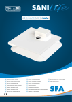
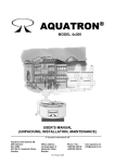
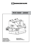
USER’S MANUAL
UNPACKING, INSTALLATION,
MAINTENANCE
4x100, 4x200 och 4x300
AQUATRON®
AQUATRON INTERNATIONAL AB
www.aquatron.se
Telefon: +46 21 560 20
E-post: [email protected]
1
© Aquatron International
1. INTRODUCTION
The liquid is flushed to a separator where urine and water is separated from faeces and paper. The
liquid will then pass through an Ultra Violet unit and may thereafter be infiltrated into the ground or
into a suitable receptacle. The solid waste is being composted in a Bio Chamber. If so wished,
composting worms may be added in order to accelerate the composting process.
1. The Aquatron System uses standard toilet fixtures.
2. When the toilet is flushed, the contents of the bowl are transported
to the Aquatron Separator where approximately 98% of the liquid is
separated by using the momentum of the flushing water (centrifugal
force and gravity). The Aquatron Separator needs no mechanical
parts.
3. The solid waste (paper and feces) falls down into the Bio Composting Chamber where it is composted by bacteria and, if desired, by
worms. If using worms, the volume of the solid waste will be reduced
by approximately 95%. The need for emptying and handling the compost is therefore reduced to a minimum. Optimal temperature for the
composting is (54-77 degrees Fahrenheit), a temperature level recommended for year-round inhabited
homes. The composting process is free from odor and insects because the Bio-Composting Chamber is ventilated and the small amount
of liquid following the paper
down into the Bio-Composting Chamber is removed by a drain at the
base of the BioComposting Chamber.
4. With high treatment requirements flowing liquid waste to a UV unit
where it is exposed to ultraviolet light which kills bacteria and viruses
or phosphorus trap to the
highest environmental discharge standards. The liquid is then equivalent to the gray water (Bathing, Washing, Wash) and can be discharged as per gray water standards. The system can also be installed without the UV-unit/phosphorus trap.
I congratulate you to your environment Aquatron toilet system!
Our experience from many satisfied customers for over 20 years is that
properly installed and properly maintained Aquatron system works satisfactorily
for many years to delight of residents and guests.
Anders Welen
Executive Director,
Aquatron International AB
IMPORTANT!
For optimal functionality it is very important that this installation manual and the maintenance instructions are being followed closely. In case of problems please
contact the main supplier.
AQUATRON INTERNATIONAL AB
www.aquatron.se
Telefon: +46 21 560 20
E-post: [email protected]
2
© Aquatron International
TECHNICAL SPECIFICATIONS
Toilets
Optional Standard toilet or urine separating toilets.
When using a normal flush, three toilets can be connected to the
same Aquatron system and eight of the larger Aquatron 4x300
PLUMBING
Pipe length: Toilet to the separator, is at least 32 inches and
maximum is 200 feet.
Pipe Slope (cases): the tube 1 yard closest to the separator is
usually about 5% (2 inches)
and the additional length of 1%, according to plumbing standards.
Pipe Dimensions: toilet pipes standard DIA. 4 inches, pipe out 2-4 inches, ventilation 2-4
inches.
INFILTRATION OR IRRIGATION (LEECHFIELD)
Aquatron connected to an approved greywater (Bathing, Washing, Wash)- infiltration.
Requirements: 2-septic tank + infiltration. We give advice and sell greywater solutions
that suit all types of land and environmental requirements.
MATERIAL
Aquatron is made from recyclable polyethylene plastic and glass-reinforced polyester.
LIFESPAN
Since everything is made of plastic; the estimated lifespan of at least 50 years.
MAINTENANCE
When the Aquatron system is installed requires minimal maintenance, keep in mind,
however, that you take a look on a monthly or quarterly basis depending on the model.
Multiple users have a history of trouble free operation and excellent composting using the
4x200 systems.
Calculate the time between emptying:
Aquatron 50, 2x50 90 and 6-15 months
Aquatron Wagon 12-24 months
Aquatron 4x100, 4x200 and 4x300 (section) 12-72 months
POWER CONSUMPTION
None; unless using a UV unit.
UV UNIT
Two UV tubes. If one of the tubes fails, it activates an alarm signal.
Power consumption:
30W
PHOSPHORUS TRAP
Inlet and outlet 2” diameter. Height of inlet/outlet center: 9 inches.
Included in delivery: Polonite R 100 Lbs. phosphorus binding clay,
pH test, scoop.
AQUATRON INTERNATIONAL AB
www.aquatron.se
Telefon: +46 21 560 20
E-post: [email protected]
3
© Aquatron International
2. UNPACKING
The following parts are packed into the Bio Chamber: Separator, hose clip to fix the Separator parts together,
Wire-ring, a branch to be attached to the Bio Chamber outlet, a connection pipe between the Separator and
branch, , turning pole and, provided the UV unit is included in the delivery, a UV unit and a Waterseal to be attached to the UV
unit (For pitch changes of inlet pipes a special angled coupler double socket is provided. A mosquito net for the top of the vent
pipe is also being included.
3. PREPARATION
To install the AQUATRON toilet system you will need the following material in addition to the WC.
Components marked with an asterisk (*) are included in the shipment. Other items are to be purchased locally if necessary.
PIPES:
WC – Separator
4” Angled coupler double socket (*)
4” Pipes
2” Connecting pipe (*)
2” Soil pipe single branch (*)
2” Coupler double socket 90o bend (*)
Soil pipe bend socket
Amount depending on installation
Soil pipe single branch for 3-4”
(=#) vent pipes
For 4% change of inlet pipe pitch
Inlet pipes as needed
For the fluid outlet of the Separator
For the fluid outlet of the Bio Chamber
Connecting the two pipes above
UV unit – Grey Water
Waterseal (*)
2” Coupler double sockets
2” Pipes
P-waterseal, part of the UV unit
Amount depending on installation
Outlet pipes as needed
MISCELLANEOUS:
Course bark grinds approx. 50 litres (10-12 litres per compartment),
Or Aquatron drainage module
(purchase separately) Grounded 230 V outlet for the UV unit,
Material for platform and consoles,
2-4" pipe and coupler sockets for vent pipe (WC ventilation),
45o bend to be installed at inlet in the UV unit if a pump is installed between
Bio Chamber and UV unit.
Separator – UV unit
4. INSTALLATION
4" Bend x 90º to WC
4” Coupler double sockets
4” x #” x 45o
OF THE AQUATRON SYSTEM
Arrangement of the Bio Chamber
4.1.1 Build a platform for the Bio Chamber. For platform, see Figure 3. Place the Bio Chamber steadily on the platform.
4.1.2 Check the compartment where the system is to be installed. If low pressure occurs (e g if an oilburner
is installed), a separate room must be built for the Bio Chamber. The room must have a ventilator to
the outside air and the door should be sealed by a strip seal.
4.1.3 The Aquatron system should be installed in a frost free compartement where:
- optimal composting temperature is minimum 12° C (55° F),
- at year-round living or vermi composting a temperature above 15° C (60° F) is recommended,
- if necessary, insulate the compartment and install a themostat controlled electric heater.
If the system is installed in a vacation house which is closed during the winter season, special
precautions must be taken.
AQUATRON INTERNATIONAL AB
www.aquatron.se
Telefon: +46 21 560 20
E-post: [email protected]
4
© Aquatron International
INSTALLING THE SEPARATOR
4.2.1 Put together the upper and lower parts of the Separator. Check that the Wire-ring is fully pushed down into the Separator neck and that the wires are not crossed. The upper part of the Separator (Cyclone) should rest upon the Wire-ring.
Tighten the hose clip just as much as needed to keep the upper and lower parts of the Separator together. There must be
no space between the Cyclone and the Wire-ring,
4.2.2 Place the Separator on the Bio Chamber. Turn it so that the fluid outlet located in the bottom part faces towards the
outer side of the Bio Chamber; see Figure 2. Turn the upper part of the Separator towards the pipe coming from the WC.
Tighten the hose clip.
4.2.3 The Separator must be installed in a vertical position.
The threads should be
about 10 mm inward bent.
Adjustment flat, adjustment the
critical separatorn very simpler.
(Accessories)
NOTE:
To Aquatron Separator should only toilet connected to ensure the good separation. A dripping Wash basin drains make
the water go so slowly that the separation could be worse.
There are many installations where everything is connected to the separator, but this requires careful monitoring of the
compost from becoming too wet. Connecting the wires from the BDT system should be done after Aquatron system.
AQUATRON INTERNATIONAL AB
www.aquatron.se
Telefon: +46 21 560 20
E-post: [email protected]
© Aquatron International
5
4.3 INSTALLING THE UV UNIT
4.3.1 The UV unit should be positioned in such a way that the waste water from the Separator and the Bio Chamber can flow freely into the UV unit. It is recommended that the UV unit is placed on consoles fixed on to the wall, alternatively the UV unit may be
placed on small platform.
Make certain that the aluminium lid is positioned in such a way that it can be removed for accessing the UV fixture when replacing
burned-out UV light tubes, for inspection, cleaning of the interior of the UV Unit etc.
4.3.2 The UV unit must have its bottom surface horizontally installed.
4.3.3 The 2” Waterseal should be installed underneath the UV unit.
4.3.4 The UV unit should be connected to a 230 V grounded outlet.
4.3.5 Germicidal UV-C light tubes are made by:
- PHILIPS, type TUV 15
Platform for UV unit
Material:
(all measurements in millimetres)
1. Sideboards, 4 items
A: 95 x 20 x 300, 3 items
B: 60 x 20 x 300, 1 item
2. Legs, 4 items
80 x 80 x 120
3. Sideboard lowered 55 mm
To provide space for a 50 mm pipe from
the outlet underneath the UV unit
WARNING!
Do not expose your eyes or skin
to direct UV light.
AQUATRON INTERNATIONAL AB
www.aquatron.se
Telefon: +46 21 560 20
E-post: [email protected]
© Aquatron International
6
PHOSFORUS TRAP
A phosphorus filter is a complement to a biological treatment, such as a sand filter. Normally Aquatron systems includes a phosphorus trap or UV unit, depending on local environmental protection selects the best match.
With phosphorus trap will obtain a high level of protection along with an approved infiltration / sand filter (under the
Swedisch Environmental Protection Betraying NFS 2006:7).
A normal phosphorus trap is 10 times larger and considerably more expensive to buy and exchange of phosphorusbinding material (must have mobile crane for a change of material).
Then only the flush water goes through the phosphorus trap volume can be
reduced by 90%. The optimum is to have a high concentration of urine as possible (where all the phosphorus is) and
avoid as much plain water as possible when the only leach out the phosphor binding material.
If you have trouble getting to drop from Biotank drainage to phosphorus trap, you can ignore that lead the small
amount of flush water coming from drainage by phosphorus trap where only about 2% of the water that goes down
that road.
There is usually a disadvantage to have very low-flush toilets, then it becomes easy to stop in the tubes and paper
and faeces, which has stood still dissolve into a soup that is not possible to separate good and it ends up in
phosphorus trap and clogging the faster.
Be sure to install phosphorus trap so that it is easy to change Polonite
gravel after about a year
You can spread the use Polonite on the property and return the
phosphorus.
Polonite comes in two buckets a: 25kg
Fill the water in phosphoric trap before you pour in the Polonite.
AQUATRON INTERNATIONAL AB
www.aquatron.se
Telefon: +46 21 560 20
E-post: [email protected]
© Aquatron International
7
4.5 PIPE INSTALLATION
4.5 Pipe installation
4.5.1 Use 4” pipes between WC and Separator. For ventilation use 3-4” pipes.
4.5.2 The Separator should be connected to a 4” double socket. NOTE: The Separator must be horizontal
and its vertical line (Figure 4) perpendicular to the Bio Chamber. The inlet pipe must be fully inserted
into the socket.
4.5.3 The horizontal distance between the WC and the Separator must be minimum 1 metre and that last
metre (closest to Separator) should be pitched at 5% (5 cm), see Figure 9. At further distances the
earlier part of the pipe should have a 1% horizontal slope, or as national standards. If needed, use
the special angled coupler double socket in order to achieve the pitch transition,
NOTE: Turn the color mark of the angled coupler double socket downwards. Furthermore, check
that the inclination of the inlet pipe is smooth and that there are no depressions where fluid waste
may gather.
4.5.4 The ventilation should be installed between the WC and the Separator. The ventilation pipe should
extend above the roof.
4.5.5 If there is a large level difference between the WC-outlet and the Separator, then first install the
horizontal pipe pitched at the specified angle, and then make the necessary level adjustment with
the vertical pipe, see Figure 1.
4.5.6 The pipe installation from Separator to Bio Chamber and further on to the UV-unit/sewer is shown in
Figure 2. If needed the connecting pipe between the Separator outlet and the branch may be
shortened. The angled part of the branch which is connected to the Bio Chamber socket may be
shortened if needed. To extend the Separator outlet to the connection pipe a 12 centimetres 2" pipe
with a coupler may be included.
4.5.7 If horizontal bends are needed on the Separator inlet pipe, .
AQUATRON INTERNATIONAL AB
www.aquatron.se
Telefon: +46 21 560 20
E-post: [email protected]
© Aquatron International
8
Angled double socket for inlet pipes longer than 1 metre
Some examples of horizontal pipe bends
AQUATRON INTERNATIONAL AB
www.aquatron.se
Telefon: +46 21 560 20
E-post: [email protected]
© Aquatron International
9
VENTIALATION
4.5.7
Ventilation from Aquatron system can be placed at any position between the toilets and the separator.
Be sure to have as few bends as possible and do so grave concerns as possible to get a good draw.
If necessary, you can turn on electric fan or wind turbine.
NOTE! Do not use a vacuum-valve. The toilet ventilation must have a separate
vent pipe extending over the roof and must not be connected to the other sewer
ventilation of the house, as this may cause problems with odour and flies.
4.6 FLUSHING TEST
Ask someone to flush the WC with water only and check how much water is entering into the Bio Chamber.
If correctly installed, when flushing with water only, a maximum of 0.5 decilitres should go that way. If too
much water enters into the Bio Chamber there are two explanations:
4.6.1 If the water enters the Bio Chamber at the beginning of the flushing the velocity of the incoming
fluid is too high and the pitch is too large – decrease the pitch of the inlet pipe.
4.6.2 If the water enters the Bio Chamber at the end of the flushing the velocity of the incoming fluid is too
low and the pitch is too small – increase the pitch of the inlet pipe.
5. COMPOSTING
5.1 Start up
Drainage of the Bio Chamber: Spread a 4-6 centimetre course bark grinds layer (NOTE: Not peat moss!) into each composting
compartment of the Bio Chamber. The bark grinds should be evenly spread at the bottom of each compartment.
Add some compost from the garden in order to insert microorganisms by this the composting process will get a more rapid start.
AQUATRON INTERNATIONAL AB
www.aquatron.se
Telefon: +46 21 560 20
E-post: [email protected]
© Aquatron International
10
6.2 PUMP SOLUTION
Pump can be used to save the installation height or when the building sewer is located higher than Aquatron system fluid outlet.
Over the years we found that Saniflo pump Sanivite is reliable and easy to use.
The pump installed between the Bio Chamber outlet and phosphorus trap or UV unit inlet.
NOTE: To avoid that the liquid to splash on fluorescent lamps and fittings, a 45 ° pipe bend mounted inside the UV unit inlet. Pipe
bend towards the UV unit bottom. A reduction of between 40 mm and 50 mm purchased separately as well as 45 ° pipe bend.
Sanivite pump
AQUATRON INTERNATIONAL AB
www.aquatron.se
Telefon: +46 21 560 20
E-post: [email protected]
© Aquatron International
11
8. ERROR CHECKLIST
TYPE OF ERROR
8.1 Wet bio-bed -
CAUSE
Bad drainage
MEASURE
Check that the drainage holes are not blocked and that
the drainage layer is in accordance with the manual,
- Too much water
A: Check that the Separator was installed horizontally in the Bio
Chamber and that its vertical line is perpendicular to the Bio
Chamber.
B: Check that the Wire-ring is positioned correctly and
that the wires do not stick to the inside of the the
Separator neck. The wires should be slightly bent
towards the middle of the Separator neck, see
C: Check that the cyclone is fully pushed down into the
Separator neck and it rests firmly on the Wire-ring.
D: Check pitch of the inlet pipe. At too large pitch, fluid
enters the Bio Chamber at beginning of the flushing; at too low
pitch, fluid enters the Bio Chamber at the end of the flushing.
E: Repair the WC.
- Leaking WC
- When flushing there is
a surge or after flushing
there is still a small
string of fluid or batches
of fluid entering the
Separator
Check the pitching of the inlet pipe. It must have a smooth
slope and no depressions where fluid waste may gather,
- Wet bio-bed
See above.
- Wrong ventilation
A: The ventilation pipe is too short, it does not extend
over the roof.
B: The ventilation is coupled together with the other
sewer ventilation of the house.
C: Backflow? See Item 4.1.2. NOTE: A vacuum-valve
must not be used.
D: Check the waterseal to assure that no odour is coming
from the sewer system.
8.3 Odour when windy
- Air is pressed into
the ventilation the roof.
The ventilation pipe does not extend high enough above
It must be lengthened. Mount a vane on the ventilation pipe.
8.4 Stoppage in the
Separator
- A too high pyramid
of paper has been built
up in the Bio Chamber
Tilt the pyramid with a suitable tool, alternatively turn the
composting chamber slightly or switch to the next
compartment if needed.
- The wires in the Wirering of the Separator
are bent or crossed
Straighten the wires.
- The inlet of the
separator is not fully
inserted into the socket
Adjust,.
8.5 Stoppage in the
fluid outlet of
the Separator
- The flushing water is
entering the Separator
at too high speed
The pipe between WC and Separator has a too
large inclination. See Items 4.5.3, 4.5.5 and 4.6.
8.6 Stoppage in the
fluid outlet of the
system
- Sediments or foreign
objects in the fluid
outlet
Check that the fluid is not stopped in the UV unit or
in the waterseal underneath it. Clean the UV unit and
the waterseal from sediments and foreign objects.
8.7 Flies in the
Bio Chamber
- Wet bio-bed
See Items 8.1 and 8.2 above.
Spray the inside of the Bio Chamber with an appropriate
insecticide
8.2 Odour in the room
AQUATRON INTERNATIONAL AB
www.aquatron.se
Telefon: +46 21 560 20
E-post: [email protected]
© Aquatron International
12