1
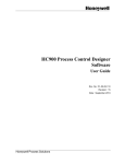
Wireless Pressure Transmitter User Manual Europe 868 MHz Band XYR 5000 Line 34-XY-25-51 Rev. 6 August 2012 Honeywell Process Solutions Wireless Pressure Transmitter User Manual Pressure Transmitter Models WG51x and WA51x Versions 1.70 or later ! Honeywell Process Solutions 1860 West Rose Garden Lane Phoenix, Arizona 85027 Important Information to the User ! • Changes or modifications not expressly approved by the manufacturer may void the user’s authority to operate the equipment. • This device is for mobile and fixed use only (not portable or body-worn). A separation distance of 20cm must be maintained at all times between the antenna and the body of the user and bodies of nearby persons. • If the Wireless Management Toolkit (RF Server) software is shutdown, the RS485 network MUST be physically disconnected from the PC as the serial port is no longer being controlled by the software and may disrupt communications between the Base Radio(s) and Analog/Digital Output Module(s). • This device has been designed to operate with an antenna having a maximum gain of 9 dBd. Antenna having a higher gain is strictly prohibited per regulations of Industry Canada. The required antenna impedance is 50 ohms. • To reduce potential radio interference to other users, the antenna type and its gain should be so chosen that the equivalent isotropically radiated power (EIRP) is not more than that required for successful communication. • The installer of this radio equipment must ensure that the antenna is located or pointed such that it does not emit RF field in excess of Health Canada limits for the general population; consult Safety Code 6, obtainable from Health Canada’s website www.hc-sc.gc.ca/rpb. Copyright 2009-12 by Honeywell International Inc. Rev. 6 – August 2012 While this information is presented in good faith and believed to be accurate, Honeywell disclaims the implied warranties of merchantability and fitness for a particular purpose and makes no express warranties except as may be stated in its written agreement with and for its customers. In no event is Honeywell liable to anyone for any indirect, special or consequential damages. The information and specifications in this document are subject to change without notice. Honeywell® and TotalPlant® are U.S. registered trademarks Of Honeywell International Inc. Other brand or product names are trademarks of their respective owners. Rev. 6 August 2012 User Manual I Honeywell Process Solutions Wireless Pressure Transmitter About This Document Revision Notes The following list provides notes concerning all revisions of this document. Rel ID Doc ID Date Notes 34-XY-25-51 Rlse. 0 12/03 1st issue of document. 34-XY-25-51 Rev. 1 08/06 Version 1.70 of software. 34-XY-25-51 Rev. 3 5/08 Updated dimensions 34-XY-25-51 Rev. 4 12/09 Updated performance spec, Materials of construction and Agency approval tables. 34-XY-25-51 Rev. 5 05/12 Battery updates 34-XY-25-51 Rev. 6 08/12 Battery updates & material change to 316 St.St. Contacts The following is a list of Honeywell contacts for including Internet World Wide Web, Telephone, Fax and Email. For Asia Pacific, Europe, North and South Americas Sales and Service For application assistance, current specifications, pricing, or name of the nearest Authorized Distributor, contact one of the offices below. ASIA PACIFIC EMEA NORTH AMERICA SOUTH AMERICA (TAC) Honeywell Process Solutions, Honeywell Process Solutions, Honeywell do Brasil & Cia [email protected] Phone: + 80012026455 or +44 (0)1202645583 Phone: 1-800-423-9883 Phone: +(55-11) 7266-1900 Or 1-800-343-0228 FAX: +(55-11) 7266-1905 FAX: +44 (0) 1344 655554 Email: (Sales) [email protected] Email: (Sales) [email protected] Email: (Sales) [email protected] or or or (TAC) [email protected] (TAC) [email protected] (TAC) [email protected] Australia Honeywell Limited Phone: +(61) 7-3846 1255 FAX: +(61) 7-3840 6481 Toll Free 1300-36-39-36 Toll Free Fax: 1300-36-04-70 China – PRC - Shanghai Honeywell China Inc. Phone: (86-21) 5257-4568 Fax: (86-21) 6237-2826 Singapore Honeywell Pte Ltd. Phone: +(65) 6580 3278 Fax: +(65) 6445-3033 South Korea Honeywell Korea Co Ltd Phone: +(822) 799 6114 Fax: +(822) 792 9015 II User Manual Rev. 6 August 2012 Honeywell Process Solutions Wireless Pressure Transmitter Table of Contents Section 1: Introduction ______________________________________ 1 1.1: Using This Manual 1.2: About the Device 1.3: CE Conformity 1.4: Unpacking 1.5: Software Compatibility 1 2 2 2 3 Section 2: Quick Start ______________________________________ 4 Section 3: Installation _______________________________________ 5 3.1: Mechanical Installation 3.1.1: Transmitter Positioning 3.1.2: Special Conditions for Safe Use 3.2: Testing Communications 3.2.1: Transmitter RSSI Diagnostic 3.2.2: Link Test 5 5 7 8 8 9 Section 4: General Configuration _____________________________ 13 4.1: Transmitter Displayed Messages 4.1.1: The Read-Only Sequence 4.2: Overall Configuration Menu Map 4.3: Setting the Transmitter Tag Name 4.4: Setting a User Password 4.5: Resetting All Transmitter Settings 13 13 14 14 15 15 Section 5: Configuring the RF Communications _________________ 16 5.1: RF Channel Selection 5.2: Baud Rate Selection 5.3: RF Identification (RF ID) Selection 16 16 17 Section 6: Configuring the Sampling and Transmission Rates _____ 18 6.1: Selecting the Normal Transmission Rate 6.2: Selecting the Normal Sampling Rate 6.3: Selecting the Abnormal Transmission Rate 6.4: Selecting the Abnormal Sampling Rate 6.5: Setting the Smart Rate Threshold 6.6: Selecting the Normal Upper and Lower Values 6.7: Selecting Rates, Thresholds, and Deadbands via WMT 18 19 20 21 22 23 24 Section 7: Configuring the Process Variable ____________________ 25 7.1: Selecting Units of Measure 7.2: Zeroing the Sensor 7.3: Setting a Measurement Offset 7.4: Trimming the Measurement 7.5: Entering a 22-Point Curve 25 26 26 27 27 Section 8: Maintaining the Transmitter ________________________ 28 8.1: Changing the Battery 28 Section 9: Technical Specification _____________________________ 29 Appendix A: Navigating User Menus __________________________ 32 Appendix B: Transmitter Displayed Message Definitions _________ 33 Appendix C: Transmitter Menu Map __________________________ 34 Rev. 6 August 2012 User Manual III Honeywell Process Solutions IV Wireless Pressure Transmitter User Manual Rev. 6 August 2012 Honeywell Process Solutions Wireless Pressure Transmitter Section 1: Introduction 1.1: USING THIS MANUAL This manual is designed to assist in installing, operating, and maintaining Honeywell Models WG51x and WA51x Pressure Transmitters. The manual is broken into sections as follows: Section 2: Quick Start This section summarizes what must be done in order to get the device installed, configured, and in operation quickly. However, it does not provide detailed or how-to information to perform the tasks outlined. Section 3: Installation This section explains mechanical installation considerations; such as Transmitter placement and Transmitter Mounting. Section 4: General Configuration In this section, general configuration options such as password protection and selecting a user password are discussed. Also covered, is the setting of a Transmitter tag name, resetting of all Transmitter settings, and a discussion of the various messages that are displayed on the Transmitter LCD. Section 5: Configuring the RF Communications This section covers the setup of the Transmitter RF Communications which allow the Transmitter to achieve communication with the Base Radio. Parameters discussed are the Transmitter RF ID, the RF channel setting and Baud Rate. Section 6: Configuring the Sampling and Transmission Rates This section aids the user in selecting the amount of time between each sample of the process, and the time between each transmission of this sample to the Base Radio. Also discussed is the use of setting an abnormal threshold in which sampling and transmission times may change during a period when the process variable is within the abnormal region. Section 7: Configuring the Process Variable This section helps the user in the selection of engineering units, as well as discussing the zeroing of the sensor, setting of a measurement offset, and trimming the process measurement. Section 8: Maintaining the Transmitter This section explains how the Transmitter should be cared for once it has been placed into service and how to change the battery. Section 9: Technical Specifications This section explains the technical specifications that are associated with this device such as power characteristics, accuracy, and operating characteristics. Rev. 6 August 2012 User Manual 1 Honeywell Process Solutions 1.2: ABOUT THE DEVICE Wireless Pressure Transmitter The Honeywell Pressure Transmitter is a reliable Radio Frequency (RF) transceiver coupled with an pressure sensor that can be used to monitor a variety of processes in hazardous and hard-to-reach areas. The time and expense of running wires often makes it difficult to measure parameters that have an economic impact on your plant operation, but the Pressure Transmitter allows you to quickly and accurately monitor those devices at a fraction of the cost, which gives you bigger and faster returns on your instrumentation investments. The Transmitters communicate in a secure, digital protocol over a band of frequencies from 869.4 MHz to 869.65 MHz. This data communication technique has been the backbone of the military’s secure communications protocols for many years. These devices require no wires, permits or licenses, and they are easily set up and installed right out of the box. You can use this device for long term monitoring in remote locations, for short-term data gathering on process conditions, or to quickly test the economic viability of a new installation. The purpose of this manual is to help you install and maintain your Honeywell Pressure Transmitter. BEFORE setting up and installing the Transmitter please setup and configure the Base Radio. 1.3: CE Conformity These models are in conformity with the protection requirements of European Council Directives: 89/336/EEC, the EMC Directive, Generic Immunity Standard for industrial environments, and 1999/5/EC, the Telecommunications Directive in accordance with EN 300 220-3-2000 – Electromagnetic compatibility and Radio spectrum Matters (ERM); Short Range Devices SRD); Radio equipment to be used in the 25 MHz to 1 000 MHz frequency range with power levels ranging up to 500 W; Part 3: Harmonized EN covering essential requirements under article 3.2 of the R&TTE Directive, EN 300 489-1-2005 – Electromagnetic compatibility and Radio spectrum Matters (ERM); Electromagnetic Compatibility (EMC) standard for radio equipment and services; Part 1: Common technical requirements, EN 300 489-3-2002 – Electromagnetic compatibility and Radio spectrum Matters (ERM); Electromagnetic Compatibility (EMC) standard for radio equipment and services; Part 3: Specific conditions for Short-Range Devices (SRD) operating on frequencies between 9 kHz and 40 GHz, and EN 61326-1997+A1+A2, Electrical Equipment for Measurement, Control and Laboratory Use – EMC Requirements. Conformity of this product with any other “CE Mark” Directive(s) shall not be assumed. 1.4: UNPACKING Remove the Packing List and check off the actual equipment received. If you have any questions about your shipment, please call your Honeywell Representative. Upon receipt of the shipment, inspect the container for any signs of damage in transit. Especially take note of any evidence of rough handling. Report any apparent damage immediately to the shipping agent. Please note that sometimes units are assembled with accessories when shipped. Inspect the shipment carefully if you think that something is missing. This is rare, as we take considerable care to pack units for shipment, but it does sometimes happen. Please give us a call and we may be able to resolve this matter quickly over the phone. 2 User Manual Rev. 6 August 2012 Honeywell Process Solutions Wireless Pressure Transmitter NOTE Please note that the carrier will not honor any claims for damage unless all shipping materials are saved for their examination. If damage is found during examining and removal of the contents, save the packing material and the carton. 1.5: SOFTWARE COMPATIBILITY Software for Honeywell is revised periodically. Internal device software may contain portions that are not compatible with previous versions of the Wireless Management Toolkit software. To ensure software compatibility, Wireless Management Toolkit software version 1.70.138 or later must be used. If you believe you are experiencing software compatibility issues please call your local representative or email [email protected] (e-mail). Rev. 6 August 2012 User Manual 3 Honeywell Process Solutions Wireless Pressure Transmitter Section 2: Quick Start This section summarizes what must be done in order to get the device installed, configured and in operation quickly. However, it does not provide detailed or how-to information to perform the tasks outlined. 1. Place the Transmitter in the desired location of operation. Note: Trimming and zeroing of the measurement may be necessary before the device can be placed in service. If trimming is required, perform steps 7-14 prior to placing device in service. 2. 3. Ground the Transmitter via conduit or bonding strap. Turn on the Transmitter by simultaneously pressing and holding the ENTER and NEXT buttons until the unit powers up. Set RF CHAN setting equal to the Base Radio’s RF Channel. Set BAUD RT setting equal to the Base Radio’s Baud Rate. Set RF ID number to be a unique value between 1 and 42. Select normal transmission rate. Select normal sampling rate. Select abnormal transmission rate. Select abnormal sampling rate. Set normal upper and lower values. Select engineering measurement units. Zero the sensor. Trim the sensor. 4. 5. 6. 7. 8. 9. 10. 11. 12. 13. 14. ! Warning ! If the Transmitters have been running for an extended period of time with no signal from the Base Radio (the Base Radio is off or not present), the Transmitters will only search for the Base Radio every one hour or so. Turning the Transmitters off and back on will cause them to begin searching immediately. If the “RF OFF” message is being displayed on the Transmitter LCD, perform the following: • If a “NO RF” message is being displayed on the Transmitter LCD, check the following: • • • • 4 Set the RF CHAN setting equal to the Base Radio’s RF Channel. Is the Transmitter set to the above listed settings? Is the Base Radio on? Do the Transmitter and Base Radio settings match? (See Section 5 of Transmitter and Base Radio User Manuals) Are the Base Radio and Transmitters unable to communicate due to obstructions or distance? (See Section 3.1.1: Transmitter Positioning) User Manual Rev. 6 August 2012 Honeywell Process Solutions Wireless Pressure Transmitter Section 3: Installation 3.1: Mechanical Installation In this section, mechanical installation instructions are discussed for the various setup capabilities of the Pressure Transmitter. Each Honeywell Pressure Transmitter is a rugged device which provides optimal performance when installed with careful consideration. Installation practices greatly affect the life that you can expect from your Honeywell Pressure Transmitter. ! Warning ! During installation do not apply force to the instrument housing or antenna. Use a proper wrench for all installations. Failure to use correct installation procedures can cause damage to the Base Radio. Give careful consideration to the environment where you will be installing your instrument. Avoid installations that expose the device to excess temperature, high vibration, considerable shock, or exposure to dripping condensate or corrosive materials. Also avoid installing the device in an unserviceable location. Most often these problems can be avoided with some thought at the time of installation. The practices noted below are generally recommended, but they can only act as a guideline and cannot cover all possible variations. The final installation must be made at the discretion and approval of the user. You must be the judge of the actual installation. Dimensioned mechanical drawings for aid in mechanical installation are located in Section 9: Technical Specifications 3.1.1: Transmitter Positioning Correct positioning of the Transmitter will ensure the best performance of the device. When planning the positioning of the Transmitters there are a few parameters that must be paid attention to: • The top of the Transmitter should point upwards. This is important to remember when positioning the WG51x and WA51x. For this reason, these Transmitters are usually attached to an elbow fitting coming out of the tank you are monitoring. • All Transmitters should maintain an approximate spacing of at least six feet apart from one another. Should you need to put Transmitters closer than six feet, please see Section 3.1.1.1 entitled “Technique for Close Positioning of Transmitters”. The line of sight range between a Transmitter and Base Radio is 600 m (2000 ft). Note that this range is reduced by the amount of RF Noise present, obstructions, and the material properties of the obstruction • Only place the Transmitter in ambient operating temperatures of -40°F to 185°F (-40°C to 85°C). Figure 3.1: Examples of Incorrect Transmitter Positioning Rev. 6 August 2012 Figure 3.1, shown to the left, gives examples of incorrect setups according to the previously mentioned parameters. Because there are so many setup possibilities we cannot cover them all. A correct setup would make sure that the above warnings are heeded, and that the Transmitter and Base Radio are capable of communication. The RF Placement Test section will help you to determine if you have selected the correct installation points and orientations for your application. User Manual 5 Honeywell Process Solutions 3.1.1.1: Technique for Close Positioning of Transmitters Group RF ID Range 1 1-7 2 8-14 3 15-21 4 22-28 5 29-35 6 36-42 Wireless Pressure Transmitter Transmitters may be placed closely together by carefully following this procedure. If this procedure is not followed, the communication range of the Transmitters will be significantly reduced and the Transmitters may eventually lose communication with the Base Radio entirely. This procedure is easy to implement, but please read carefully for a full understanding. The Base Radio synchronizes with the Transmitters in synch groups of 7, organized by their RF ID numbers. If you want to place two Transmitters closer than 6 feet, make sure that you have set them in different groups. Note that this only applies to Transmitters that are communicating with the same Base Radio. The groups are defined in the table to the left. For example, if two Transmitters are placed one foot apart and the first Transmitter has an RF ID number of 027, that means it is in the 4th group (22-28). The second Transmitter must have an RF ID number that is in another group (less than 22 or greater than 28). Setting the RF IDs of two closely spaced Transmitters so that the RF ID numbers are greater than 7 apart ensures that the Transmitters are in different Base Radio sync groups. This allows the closely spaced Transmitters to properly receive their synchronization signal from the Base Radio and maintain their proper communication and range. You can also ensure that closely spaced Transmitters maintain their synchronization with their Base Radio by simply assigning each of the two closely spaced Transmitters to talk to a different Base Radio. Either way, following this process will keep the Base Radio and Transmitters properly synchronized for long-term communication. 6 User Manual Rev. 6 August 2012 Honeywell Process Solutions 3.1.2: Special Conditions for Safe Use Wireless Pressure Transmitter Parts of the enclosure are non-conducting and may generate an ignitioncapable level of electrostatic charge under certain extreme conditions. The user should ensure that the equipment is not installed or used in a location where it may be subjected to external conditions (such as high-pressure steam) which might cause a build-up of electrostatic charge on nonconducting surfaces. Additionally, the equipment must be cleaned only with a damp cloth. As aluminum may be used at the accessible surface of this equipment, in the event of rare incidents, ignition sources due to impact and friction sparks could occur. This shall be considered when the Honeywell XYR5000 series Transmitters are being installed in locations that specifically require group II, category 1G equipment. The following Honeywell Transmitter types have flying leads and require installation in suitable conduit. The leads shall be terminated such that they are provided with adequate protection appropriate to the intended installation location. • • • • • WT533R-a-3G RTD Temperature Transmitter, Split Unit WT533T-a-3G T/C Temperature Transmitter WW593-3G Dual Switch Input Transmitter WI555-3G Dual 4/20mA Transmitter WI556-3G Dual 0-10V Transmitter The Sensor terminals and the Input SW terminals of the following Honeywell XYR-5000 series Transmitter types shall be installed as separate intrinsically safe circuits: • • Rev. 6 August 2012 WI555-3G Dual 4/20mA Transmitter WI556-3G Dual 0-10V Transmitter User Manual 7 Honeywell Process Solutions Wireless Pressure Transmitter 3.2: Testing Communications Remember, proper placement of the Transmitter will optimize your RF communication range and capabilities. Perhaps the best test to perform before mechanically mounting the unit is a quick hand-held test. There are two types of tests you can conduct: the RSSI (Received Signal Strength Indicator) Diagnostic and the Link Test. The RSSI Diagnostic measures the strength of the signal at the Transmitter. The Link Test measures the throughput of data sent to and from the Transmitter. The Link Test may be conducted from the Transmitter, Base Radio, or through WMT. The RSSI Diagnostic should be conducted first to determine if the Base Radio is communicating with the Transmitter. Then the Link Test may be performed to test the validity of the installation. To perform these tests you should have a good idea of where the Base Radio will be placed (for more information see Section 3 of the Base Radio User Manual). Place the Base Radio in the desired area and power on. Make sure that the Base Radio and Transmitter are on the same RF Channel and Baud Rate (See Section 5). You may also have to increment the number of Transmitters with which the Base Radio is communicating (See the Base Radio User Manual Section 4.3). Once both the Base Radio and Transmitter are set up to be on the same network, make sure communication is established by looking at the Transmitter LCD for the ‘RF OK’ message in the Read-Only Sequence (see Section 4.2.1). After communications have been established, go to Section 3.2.1 for the RSSI Diagnostic or Section 3.2.2 for the Link Test. 3.2.1: Transmitter RSSI Diagnostic The Transmitter should be placed in RSSI Diagnostic mode to determine the signal strength at the location of the equipment to be monitored. The RSSI Diagnostic, located in the Transmitter’s diagnostic menu, displays the RF signal strength in one of seven ranges. The signal strength is displayed on the LCD using a combination of ‘>’ and ‘_’ characters. Full signal strength is displayed as “> > > > > > >” while minimum signal strength is displayed as “> _ _ _ _ _ _”. If the Transmitter is not communicating with the Base Radio (i.e. NO RF), all underscore characters will be displayed (“_ _ _ _ _ _ _”). The RSSI is measured every time the Transmitter receives a message from the Base Radio. The signal strength of the received message from the Base Radio is calculated during this time. The actual signal strength in dBm for each range is shown below: > > > > > > > Less than Between Between Between Between Between Greater than -90 dBm & -85 dBm & -85 dBm -80 dBm -105 dBm & -100 dBm & -95 dBm & -105 dBm 8 -100 dBm User Manual -95 dBm -90 dBm -80 dBm Rev. 6 August 2012 Honeywell Process Solutions 3.2.1 Continued Wireless Pressure Transmitter To place the Transmitter in RSSI Diagnostic mode follow the menu map shown below in Figure 3.2. Note that the RSSI menu is under the DIAGNSE menu and not the CONFIG menu. Figure 3.2: Menu Map to RSSI Mode Now that the Transmitter is in the RSSI mode, bring the Transmitter close to the equipment you wish to monitor. Look at the LCD; notice the ‘>’ will constantly fluctuate. One should estimate an average value based on these fluctuations. The ideal signal integrity is seven arrows. Once you have verified that you are receiving a signal, you should check to make sure the Transmitter is communicating properly with the Base Radio. To do so, exit the RSSI by pressing ENTER, and then navigate to EXIT? of the diagnostic menu and return to the Operations Sequence shown in Figure 4.1 in Section 4.2. If you see a NO RF message, then you do not have satisfactory RF communication with the Base Radio. If your application allows, move the Transmitter to a different position and check again for communications. 3.2.2 Link Test The Link Test measures the wireless link performance of a Transmitter running in its normal operating mode. Messages are sent from the Transmitter to the Base Radio at a predefined interval called the Transmit Rate (see Section 6.1). Each message contains data for the previous time period (since the last transmit). The Link Test looks at the wireless performance going in both directions, from the Transmitter to the Base Radio and vice versa, and comes up with a rating. The result that appears on the display shows the determined link strength. In order to perform this test, the Transmitter must be communicating on the same channel and baud rate as the Base Radio. See Section 5 to configure communications. The Link Test may be conducted from the Transmitter, Base Radio, or through WMT. Running the Link Test from WMT is ideal for testing communications for an installation with remote or hard-to-get-to Transmitters. To conduct the Link Test from a Base Radio, see Section 3.2.2.2. To conduct the Link Test from WMT, see Section 3.2.2.3. 3.2.2.1 Conducting a Link Test from the Transmitter Rev. 6 August 2012 The Link Test is located in the Transmitter’s diagnostic menu (see Figure 3-3). User Manual 9 Honeywell Process Solutions Wireless Pressure Transmitter 3.2.2.1 Continued Figure 3.3: Transmitter Link Test Using the NEXT and ENTER buttons, navigate to Link Test, and press the ENTER button to begin the test. The Transmitter will begin to test the link in both directions (to and from the Base Radio). During this time, the word TEST will appear on the LCD display. When the test is complete, the Transmitter will display the quality of the link. Be aware that the Transmitter uses the configured Baud Rate and transmission rate to perform this test. The length of time it will take to perform this test is dependent upon how fast the device is normally transmitting. When enough messages have been observed, a link strength will be shown on the display. >>>>> indicates the strongest link, while > indicates the weakest link. The Link Test will continue to be evaluated and the rating on the screen may adjust itself. Keep in mind that the longer the Link Test runs the more data the Transmitter will have to evaluate. 3.2.2.2 Conducting a Link Test from the Base Radio The Transmitter installation site should strive to place the Transmitter in a location where it receives the highest number possible. A stronger link means less data re-transmits and better battery life. When the Link Test is conducted from a Base Radio, it measures the link strength between a selected Transmitter and the Base Radio. The Link Test data must be configured to match the communication parameters of the Transmitter from which you want to test. The Link Test is located in the Base Radio's diagnostic menu (see Figure 3.4). To conduct a Link Test from the Base Radio, Navigate to Link Test, and press the Enter button. Next enter the RF ID for the Transmitter that you want to test. Then select the Normal Transmit rate that matches that of the Transmitter. If the Transmitter is transmitting at a different rate than the one you select in this menu, your results will be invalid. Once the Normal Transmit Rate is selected, the Link Test will immediately start. The Base Radio will begin to test the link from the Transmitter. During this time, the word TEST will appear on the LCD display. When the test is complete, the Base Radio will display the quality of the link. Be aware that the length of time it takes to perform this test is dependent upon how fast the Transmitter is normally transmitting. 10 User Manual Rev. 6 August 2012 Honeywell Process Solutions Wireless Pressure Transmitter 3.2.2.2 Continued Figure 3.4: Base Radio Link Test When enough messages have been observed, a link strength will be shown on the display. >>>>> indicates the strongest link, while > indicates the weakest link. The Link Test will continue to be evaluated and the rating on the screen may adjust itself. Keep in mind that the longer the Link Test runs the more data the Transmitter will have to evaluate. The Transmitter installation site should strive to place the Transmitter in a location where it receives the highest number possible. A stronger link means less data re-transmits and better battery life. 3.2.2.3 Conducting a Link Test from WMT To conduct a Link Test from WMT, make sure that WMT is running on the PC attached to the Base Radio. Then go to the Transmitter view, and right-click on the Transmitter you want to test Received data transmission from (Figure 3-5). Select Wireless Data Loss Test… from the popup menu. The Wireless Data Loss Test window appears (Figure 3-6). The name of the Transmitter being tested appears in the title bar in parenthesis. Figure 3.5: WMT Transmitter View Rev. 6 August 2012 User Manual 11 Honeywell Process Solutions Wireless Pressure Transmitter 3.2.2.3 Continued Figure 3.6: Wireless Data Loss Test In the top of the window, you can configure the test to run for a specified amount of time. The longer the test, the more data the test will have to do an evaluation. Type the length of time that you want to run the test and click Begin to start. After the test has completed, it will restore the previously configured Transmit Rate. During the test, the communications reliability is evaluated while the Transmitter is running under normal operating conditions. As the test runs, a link strength will be shown in the lower right hand corner of the window. >>>>> indicates the strongest link, while > indicates the weakest link. The Link Test will continue to be evaluated and the rating on the screen may adjust itself for the specified amount of time. 12 User Manual Rev. 6 August 2012 Honeywell Process Solutions Wireless Pressure Transmitter Section 4: General Configuration This section discusses the generalities for configuring the Transmitter via the NEXT and ENTER buttons. The subsections are as follows: 4.1: Transmitter Displayed Messages 4.1.1: The Read-Only Sequence 4.2: The Overall Configuration Menu Map 4.3: Setting the Transmitter Tag Name 4.4: Setting a User Password 4.5: Resetting All Transmitter Settings 4.1: Transmitter Displayed Messages To turn the Transmitter on, press and hold both the NEXT and ENTER buttons for a few seconds. Upon power up, the Transmitter will display the Power-Up Sequence, and then go into the Operations Sequence. These Sequences are shown in Figure 4.1 below: NOTE During configuration and testing, keep Transmitters at least six feet from the Base Radio and other Transmitters. Figure 4.1: Transmitter Power-Up and Operations LCD Sequences 4.1.1: The Read-Only Sequence Once the Transmitter is in the Operations Sequence, a user may access the READ-ONLY Sequence without a password by simply pressing the ENTER button at any time. The Read-Only Sequence, as shown in Figure 4.2, displays extra information about the current settings of the Transmitter that are not seen during the Operations Sequence, but does not allow any changes to be made to these settings. Figure 4.2: The Read-Only Sequence Rev. 6 August 2012 User Manual 13 Honeywell Process Solutions 4.2: Overall Configuration Menu Map Wireless Pressure Transmitter A complete Transmitter Menu Map is shown in Appendix B. Below is an overall view of the configuration menu to aid the user in setting up the Transmitter for proper operation. NOTE The user must enter a four digit password to enter the CONFIG and DIAGNSE. The FACTORY menu is for factory use only. The default user password is 0000. For more information on the password see Section 4.4. Figure 4.3: Overall Configuration Menu Map 4.3: Setting the Transmitter Tag Name* Figure 4.4: Menu Map to Tag Name Setting Using Wireless Management Toolkit Each Transmitter has a user-settable Transmitter Tag Name. This tag name is displayed upon Transmitter power up, and when the Read Only Sequence is selected. The Tag Name is a 21-character string that is displayed in three separate 7-character flashes on the Transmitter LCD. The user may choose from A-Z, 0-9, a dash (“-“), and an underscore (“_”). The underscore has a special meaning to the software inside the Transmitter. For example, if you have a Tag Name that is only 5 characters long, then you do not want to wait for the rest of the 16 characters to be displayed on the LCD. So if your Tag Name was “TRAP1”, you would want to enter the Tag Name like this: “TRAP1 _ _ _ _ _ _ _ _ _ _ _ _ _ _”. If you have the Wireless Management Toolkit software this menu option will not be accessible via the Transmitter once the Transmitter detects that the software is being used (See Appendix A for more details). The tag name should be entered using the Wireless Management Toolkit software. To do so, when the software is in the Transmitter view (See Section 8.1 of the Wireless Management Toolkit User Manual), right-click the Transmitter icon and select Rename, then enter the tag name you wish the Transmitter to have. This tag name will then be downloaded to the Transmitter and can be displayed by pressing the ENTER button when the unit is in the Operations Sequence (See Section 4.1.1 of this manual) 14 * Indicates that Menu is Disabled if Wireless Management Toolkit is detected. (See Appendix A) User Manual Rev. 6 August 2012 Honeywell Process Solutions 4.4: Setting a User Password* Wireless Pressure Transmitter Each Transmitter has a password that will lock out undesired users from making changes to the Transmitter. Any user may still view some of the Transmitter settings by pressing the ENTER key during the Operations Sequence and viewing the Read-Only Sequence. The password is a four-digit password. The factory default is 0000. If you wish to select a different password, one may be entered via WMT. To do so, enter the configuration dialog box (See Appendix A). From the con- Figure 4.5: Menu Map to Password Setting figuration dialog box, click on the General tab to bring up the general information as shown in Figure 4.6. If you have the Wireless Management Toolkit software this menu option will not be accessible via the Transmitter once the Transmitter detects that the software is being used (See Appendix A for more details). You can set the Transmitter password for this device by entering a fourdigit number in the Transmitter Password field. Once a password has been entered, click OK to save and download the password to the Transmitter. Figure 4.6: Password Setting Using Wireless Management Toolkit 4.5: Resetting All Transmitter Settings NOTE Resetting the Transmitter by using the DEFAULT menu option will not reset the TRIM or OFFSET values. Rev. 6 August 2012 Please note that the password only protects the Transmitter from unauthorized configuration via the NEXT and ENTER buttons. WMT requires a user login password to gain access to all configuration parameters. However, user accounts are available and can be set with different access levels and restrictions (For more information on user accounts see the WMT User Manual Section 8.4). To reset all Transmitter settings to their default state, the user must navigate to the DEFAULT menu option in the CONFIG menu via the keypad. Once at the default menu option, pressing the ENTER button will display ‘RESET?’ on the LCD; which asks if you are sure you want to reset the device to its default configuration. You will then be prompted with ‘NO’ on the LCD. Pressing the ENTER button while ‘NO’ is being displayed will NOT reset the device. Pressing the NEXT button will display ‘YES’ on the LCD. If you press the ENTER button while ‘YES’ is being displayed the device will be reset. * Indicates that Menu is Disabled if Wireless Management Toolkit is detected. (See Appendix A) User Manual 15 Honeywell Process Solutions Wireless Pressure Transmitter Section 5: Configuring the RF Communications ! Warning ! If the Transmitters have been running for an extended period of time with no signal from the Base Radio (the Base Radio is off or not present), the Transmitters will only search for the Base Radio every one hour or so. Turning the Transmitters off and back on will cause them to begin searching immediately. 5.1: RF Channel Selection In order for the Transmitter and the Base Radio to communicate, they must be on the same RF Channel and must be transmitting at the same Baud Rate. While all Transmitters and Base Radios are set to default configurations at the factory, if any configuration differences are present the Base Radio will not be able to communicate with the Transmitters. The subsections are as follows: 5.1: RF Channel Setup 5.2: RF Baud Rate Setup 5.3: RF Identification Setup The RF Channel defines a set of frequencies on which communication takes place between the Base Radio and the Transmitter. Each RF Channel has a different set of frequencies, thus allowing the user to have multiple different wireless networks co-existing throughout the same facility. All Base Radios and Transmitters can be set to one of 4 different RF channels. The only Transmitters recognized by a particular Base Radio are the units that are on the same RF Channel as that Base Radio. This allows the user to decide which Transmitters communicate with each Base Radio. The RF Channel can be thought of as a set of walkie-talkies. If both walkie-talkies are on channel one they can communicate. If a walkietalkie is on channel one and the other is on channel two, they cannot communicate. Likewise, if two walkie-talkies are on channel one and two other walkie-talkies are on channel two, the walkie-talkies on channel one cannot hear what is being transmitted by the walkie-talkies on channel two. Figure 5.1: Menu Map to RF Channel Setting Each Transmitter comes from the factory with the RF Channel set to OFF. This means the Transmitter will not communicate to any Base Radio. To set the Transmitter for communication, first determine the channel that you want to use. Then follow the Transmitter menu map shown in Figure 5.1 to configure the RF Channel. Once in the RF Channel menu, increment it by pressing the NEXT button. When selecting this value, do not choose an RF Channel that is currently being used by other Honeywell Wireless Systems as this can cause communication problems. 5.2: Baud Rate Selection 16 The RF Baud Rate refers to the speed at which the Base Radio and Transmitters communicate. The Baud Rate is not configurable. It is set at 4.8K. This allows the Transmitter to have a fastest update rate of 5 seconds and a range of 360m to 600m (1200 ft to 2000 ft) Line of Sight. User Manual Rev. 6 August 2012 Honeywell Process Solutions 5.3: RF Identification (RF ID) Selection Wireless Pressure Transmitter Each Transmitter is identified by the Base Radio and WMT, according to the RF ID given to that particular unit. Two Transmitters on the same RF Channel CANNOT have the same RF ID (if you do not know the RF Channel, see section 5.1). When the Transmitter is in the Operations Sequence, pressing the ENTER button displays the Read-Only Sequence on the LCD. The RF of that unit will be displayed in the format: ID 3. All Transmitters in your system are set to a default RF ID number upon shipment. For example, if you have ordered a Base Radio and three Transmitters, the Transmitters will be configured to ID’s 0, 0 and 0. You must set these units to three different RF IDs between 1 and 42. The Transmitters in this example could be set to RF IDs 1, 2, and 3. First determine the RF ID’s you’d like to give each unit. Then follow the menu map shown in Figure 5.3 to configure the RF ID. The factory default is RF ID 0, which disables the RF communication of the unit. Figure 5.3: Menu Map to RF ID Setting Once you have selected the RF ID you wish to use for this particular Transmitter, exit the menus and return to the Operations Sequence. The Transmitter should now be successfully configured to the Base Radio. To check this, press ENTER while the Transmitter is in the Operations Sequence for the Read-Only Sequence to be displayed. You may see an RF SYNC message displayed on the Transmitter LCD. This means that the Transmitter and Base Radio are attempting to synchronize communications. If this is successful, the RF Status will display an RF OK message. If this is unsuccessful, the RF Status will display a NO RF message. Also notice the two small arrows on either side of the LCD; if they are fluctuating up and down, that indicates the Transmitter and Base Radio are successfully communicating. If only one or none of the arrows are moving then they are not communicating successfully. Rev. 6 August 2012 User Manual 17 Honeywell Process Solutions Wireless Pressure Transmitter Section 6: Configuring the Sampling and Transmission Rates The Pressure Transmitter is very versatile with many programmable features and can be used in numerous different applications. Because no two applications are the same, some configuration is required for each unit. This section will walk you through the initial configuration of these sample and transmit settings. The subsections are as follows: 6.1: Selecting the Normal Transmission Rate 6.2: Selecting the Normal Sampling Rate 6.3: Selecting the Abnormal Transmission Rate 6.4: Selecting the Abnormal Sampling Rate 6.5: Setting the Smart Rate Threshold 6.6: Selecting the Normal Upper and Lower Values 6.7: Selecting Rates, Thresholds, and Deadbands via the Software 6.1: Selecting the Normal Transmission Rate* The Normal Transmission Rate is the interval in which the Transmitter transmits data to the Base Radio. The Transmitter is in a “sleep” mode to save power during the operations sequence. This mode turns off most of the electronics on the unit, with the exception of the LCD, in order to preserve battery life. The Transmitter will then ‘wake up’ every Normal Sampling Period and take the necessary process value readings. The Transmitter will then transmit these readings to the Base Radio on an interval determined by the Normal Transmission Rate. In order to properly set the Normal Transmission Rate, you must first determine how often you need updates from the Transmitter. You have a selectable range of 5, 10, 15, 20, 40 seconds and 1 minute. The factory default is 10 seconds. If all of the data does not get through, the data is resent the following second. This prevents data from being lost. Figure 6.1: Menu Map to Normal Transmission Rate Setting Using Wireless Management Toolkit 18 If you have the Wireless Management Toolkit software this menu option will not be accessible via the Transmitter once the Transmitter detects that the software is being used (See Appendix A for more details). An explanation of how to select the Normal Transmission Rate using the Wireless Management Toolkit software can be found in section 6.7. * Indicates that Menu is Disabled if Wireless Management Toolkit is detected. (See Appendix A) User Manual Rev. 6 August 2012 Honeywell Process Solutions 6.2: Selecting the Normal Sampling Rate* Wireless Pressure Transmitter The Normal Sampling Rate is the interval in which the Transmitter reads the monitored process value. As previously mentioned, the Transmitter is in “sleep” mode to save power during the operations sequence. This mode turns off most of the electronics on the unit (with the exception of the LCD) in order to preserve battery life. The Transmitter will then ‘wake up’ for every Normal Sampling Period and take the necessary process value readings. Notice that the minimum speed of the Normal Sampling Rate is dependent on the Normal Transmission Rate setting selected (see Section 6.1). The Sampling Rate cannot be set slower than the Normal Sampling Rate. Thus, if you selected the Normal Transmit Rate setting to be 10 Seconds the Normal Sampling Rate must be set to 10 Seconds or faster. A complete table of these parameters is shown below. Baud Rate (communication range) (speed of updates) Normal and Abnormal Transmit Rates Normal and Abnormal Sampling Rates Figure 6.2: Incorrect Sampling Rate 4.8K 600 m (2000 ft) 5 Seconds 5 Seconds or Greater Equal to Transmit Rate or Less In order to properly set the Normal Sampling Rate determine how often updates are needed from the Transmitter when the process being monitored is operating under normal conditions. The Transmitter has a selectable range of 1-5, 10, 15, 20, 30, and 60 seconds depending on the Normal Transmission Rate. The factory default is 1 second. However, the more frequently the Transmitter wakes up to check the monitored device, the faster you will use up the battery life of the Transmitter. Figure 6.2 is an example of what happens when the Normal Sampling Rate is too slow for the process being monitored. Notice how the rise in the voltage level falls between two normal samples, and thus goes completely undetected. Figure 6.3 is an example of what happens when the Normal Sampling Rate is correctly set for the device that is being monitored. Notice how this setting makes it possible to sample the rise in the voltage level. Figure 6.3: Correct Sampling Rate Once you have decided on the proper Normal Sampling Rate select this setting from the Transmitter or through WMT. Using Wireless Management Toolkit Figure 6.4: Menu Map to Normal Sampling Rate Setting Rev. 6 August 2012 If you have the Wireless Management Toolkit software this menu option will not be accessible via the Transmitter once the Transmitter detects that the software is being used (See Appendix A for more details). An explanation of how to select the Normal Sampling Rate using the Wireless Management Toolkit software can be found in section 6.7. * Indicates that Menu is Disabled if Wireless Management Toolkit is detected. (See Appendix A) User Manual 19 Honeywell Process Solutions 6.3: Selecting the Abnormal Transmission Rate* NOTE If the device is not configured to check for abnormal process conditions using the Sampling Bands (section 6.6.2), the Abnormal Transmission Rate is not used and this section can be ignored. Wireless Pressure Transmitter The Abnormal Transmission Rate is identical to the Normal Transmission Rate with one exception. The Abnormal Transmission Rate only applies while the Transmitter is in an abnormal condition (see Section 6.6 Selecting the Normal Upper and Lower Values). This allows an increase or decrease in the frequency of information you receive depending on the operating conditions of the process being monitored. In order to properly set the Abnormal Transmission Rate, determine how often updates are needed from the Transmitter when the process being monitored is operating under normal conditions. The Transmitter has a selectable range of 5, 10, 15, 20, 40 seconds and 1 minute. Figure 6.5 is an example of how the device switches transmission rates from Normal Transmission Rate to Abnormal Transmission Rate. Note how the first abnormal transmission is sent immediately when the Normal Upper Value set point is exceeded. The next transmission will then follow this immediate transmission by 10 seconds (or whatever the Abnormal Transmission Rate is set to). The transmissions will continue at this interval until the process value drops below the Normal Upper Value set point. Once the process value drops below this set point, another transmission is sent to the Base Radio. The transmissions will then be sent at the Normal Transmission Rate of one minute (the current setting for the Normal Transmission Rate) from the time of the last abnormal transmission. Figure 6.5: Example of Abnormal Transmission Rate Setting The user should also note that the transmission time depends on the sampling rate, and when the process value is sampled. If the Normal Sampling Rate is 30 seconds, then the process value may be above the Normal Upper Value for up to 29 seconds before an abnormal condition is detected. This means that the transmission could be as late as 29 seconds after the process value exceeded the Normal Upper Value. Once you have decided the proper time for the Abnormal Transmission Rate, select this setting from the Transmitter or through WMT. Figure 6.6: Menu Map to Abnormal Transmission Rate Setting Using Wireless Management Toolkit If you have the Wireless Management Toolkit software this menu option will not be accessible via the Transmitter once the Transmitter detects that the software is being used (See Appendix A for more details). An explanation of how to select the Abnormal Transmission Rate using the Wireless Management Toolkit software can be found in section 6.7. * Indicates that Menu is Disabled if Wireless Management Toolkit is detected. (See Appendix A) 20 User Manual Rev. 6 Honeywell Process Solutions 6.4: Selecting the Abnormal Sampling Rate* NOTE Note If the device is not configured to check for abnormal process conditions using the Sampling Bands (section 6.6.2), the Abnormal Sampling rate is not used and this section can be ignored. Wireless Pressure Transmitter The Abnormal Sampling Rate is identical to the Normal Sampling Rate with one exception. The Abnormal Sampling Rate only applies while the Transmitter is in an abnormal condition (see 6.6 Selecting the Normal Upper and Lower Values). This allows an increase or decrease of the frequency of information you receive depending on the operating conditions of the process being monitored. In order to properly set the Abnormal Sampling Rate, determine how often updates are needed from the Transmitter when the process being monitored is operating under normal conditions. The Transmitter has a selectable range of 1-5, 10, 15, 20, 30 seconds and 1 minute. Figure 6.7 is an example of how the device switches sampling methods from Normal Sampling Rates to Abnormal Sampling Rates. Note how the first abnormal sample is taken a few seconds after the Normal Upper Value set point is exceeded. The next sample will then follow this sample by 5 seconds (or whatever the Abnormal Sampling Rate is set to). These samples will continue at this interval until the process value drops below the Normal Upper Value set point. Once the process value drops below this set point the sampling rate will return to the Normal Sampling Rate. Also, the Abnormal Sampling must be equal to or faster than the Abnormal Transmission Rate. The user should also note that the transmission time depends on the sample rate, and when the process variable is sampled. If the Normal Sampling Rate is 30 seconds, then the process variable may be above the Normal Upper Value for up to 29 seconds before abnormal condition is detected. This means that the transmission could be as late as 29 seconds after the process variable exceeded the Normal Upper Value. Figure 6.7: Example of Abnormal Sampling Rate Setting Once you have decided the proper time for the Abnormal Sampling Rate, select this setting from the Transmitter or through WMT. Figure 6.8: Menu Map to Abnormal Sampling Rate Setting Using Wireless Management Toolkit Rev. 6 August 2012 If you have the Wireless Management Toolkit software this menu option will not be accessible via the Transmitter once the Transmitter detects that the software is being used (See Appendix A for more details). An explanation of how to select the Abnormal Sampling Rate using the Wireless Management Toolkit software can be found in section 6.7. * Indicates that Menu is Disabled if Wireless Management Toolkit is detected. (See Appendix A) User Manual 21 Honeywell Process Solutions 6.5: Setting the Smart Rate Threshold* Wireless Pressure Transmitter The Smart Rate is a feature used to trigger radio transmission of the measured data sooner than the normal or abnormal rate specified by the user. This feature is used to construct a more accurate graph of the measured process value vs. time than is possible with the fixed transmission rates, while using less battery power. If the process value changes by more than the entered Smart Rate amount within the normal or abnormal sampling rate (whichever is active), then the process variable is transmitted immediately. The normal/abnormal transmit clock is then reset upon this transmission. If no Smart Rate amount exceeding change takes place in the next normal/abnormal sample, then the next transmission will be the normal/abnormal transmit rate period. The amount entered is in the same units as were selected by the user to be displayed on the Transmitter. If the measured process value does not change by more than the entered Smart Rate amount within the time between the sampling rates (whichever is active), then the process value is transmitted on the next transmit rate. If changes in the process value, which exceed the Smart Rate Amount, continue to occur, the process value is transmitted repeatedly. If you have the Wireless Management Toolkit software this menu option will not be accessible via the Transmitter once the Transmitter detects that the software is being used (See Appendix A for more details). The Smart Rate should be enabled using the Wireless Management Toolkit software. 1. 2. 3. 4. 5. Open the configuration dialog box (See Section 9.2 of the Wireless Management Toolkit User Manual). Click on the Sampling Rates tab to display the sampling rate information as shown in Figure 6.9. Select the Enable SmartRate check box. Enter the amount the process value needs to change, in order to trigger a transmission to be sent. Click OK to save and download the configuration changes to the Transmitter. Figure 6.9: Smart Rate Configuration Using Wireless Management Toolkit 22 * Indicates that Menu is Disabled if Wireless Management Toolkit is detected. (See Appendix A) User Manual Rev. 6 August 2012 Honeywell Process Solutions 6.6: Selecting the Normal Upper and Lower Values* Wireless Pressure Transmitter Each Transmitter is equipped with an analog input level upper and lower value. As the analog input is measured, it is compared to a set threshold value. Depending upon the setting of that value, whether it is enabled or not, and what the Time Deadband is, the Transmitter will enter an Abnormal condition as seen in Figure 6.10. The Normal Upper Value would be an indication that the analog input is ‘high’ and the Normal Lower Value would be an indication that analog input is ‘low’. Thus the normal operating condition for the analog input application would be found in between the two Normal Values. Figure 6.10: Normal Upper and Lower Value Example Figure 6.12: Condition “Chatter” Without Time Deadband Figure 6.11: Menu Map to Normal Upper and Lower Value Settings The Time Deadband refers to the number of seconds that the measured reading must stay in a certain condition before the Transmitter will actually switch to that condition. To select a proper Time Deadband consider the example in Figure 6.12. Notice that the Transmitter continues to cycle from Normal to Abnormal Conditions due to the fact that the input value is fluctuating around the 7.5 Volt Normal Upper Value. This is undesired. The addition of a few second delay before the Transmitter switches conditions will eliminate this “chatter”, as seen in Figure 6.13. Figure 6.13: Condition “Chatter” Elimination Due to Time Deadband Using Wireless Management Toolkit If you have the Wireless Management Toolkit software this menu option will not be accessible via the Transmitter once the Transmitter detects that the software is being used (See Appendix A for more details). An explanation of how to select the Abnormal Sampling Rate using the Wireless Management Toolkit software can be found in section 6.7. Rev. 6 August 2012 * Indicates that Menu is Disabled if Wireless Management Toolkit is detected. (See Appendix A) User Manual 23 Honeywell Process Solutions 6.7: Selecting Rates, Thresholds, and Deadbands via WMT Wireless Pressure Transmitter If you have the Wireless Management Toolkit software the Normal and Abnormal Sampling and Transmission menu options will not be accessible via the Transmitter once the Transmitter detects that the software is being used (See Appendix A for more details). These settings should be entered using the Wireless Management Toolkit software. To do so, enter the configuration menu (See Section 9.2 of the Wireless Management Toolkit User Manual). Once in the configuration menu click on the Sampling Rates tab to bring up the sampling rate information, as shown in Figure 6.14. To select the Normal Transmission Rate, select one of the time periods from the drop box. Next, select an Abnormal Transmission Rate in the same manner. Note that the Normal and Abnormal Transmission Rate can be the same. Once the transmission rates have been selected, the user should select the desired sampling rates. Note that the sampling rate must be equal to or faster than the associated transmit rate. For example, in Figure 6.14 the Normal Transmission Rate is set to 10 seconds and the Normal Sampling Rate is also set to 10 seconds. This is a valid configuration. Another example in Figure 6.14 is the Abnormal Transmission Rate being set to 3 seconds and the Abnormal Sampling Rate being set to 1 second. If the user incorrectly enters the Transmission and Sampling Rates, a message will be displayed explaining this to the user. The user will not be allowed to leave this screen before the setting is corrected. Figure 6.14: Sampling and Transmission Rate Selection Using the Software If you have the Wireless Management Toolkit software the Normal and Normal Upper and Lower Value menu options will not be accessible via the Transmitter once the Transmitter detects that the software is being used (See Appendix A for more details). These settings should be entered using the Wireless Management Toolkit software. To do so, enter the configuration menu (See Section 9.2 of the Wireless Management Toolkit User Manual). Once in the configuration menu click on the Sampling Bands tab to bring up the sampling band information as shown in Figure 6.15. To set a limit to the normal condition, enable the limit by clicking on the Use Input X Limit check box. Then enter the value and time deadband for the limit (for more details see Section 6.6 of this manual). Figure 6.15: Normal Upper and Lower Value Selection Using the Software 24 User Manual Rev. 6 August 2012 Honeywell Process Solutions Wireless Pressure Transmitter Section 7: Configuring the Process Variable This section helps the user in the selection of engineering units, as well as discussing the setting of a measurement offset and trimming the process measurement. The subsections are as follows: 7.1: Selecting Units of Measure 7.2: Zeroing the Sensor 7.3: Setting a Measurement Offset 7.4: Trimming the Measurement (Entering a 22-Point Curve) 7.1: Selecting Units of Measure* Pressure Units Display Characters Pounds per in2 PSI Bar BAR Millibar MBAR Pascals PASCAL Kilopascal KPASCAL Torr TORR Atmospheres ATMS Inches of water @ 4°C IN H2O Inches of Mercury IN HG Feet of Water FT H2O Millimeters of Mercury MM HG Grams / cm2 GM/SQCM Kilograms / cm2 KG/SQCM The Transmitter can be used in many different types of applications. To accommodate these various options, there are various engineering units that can be selected. To select units of measurement, follow the Transmitter menu map shown in Figure 7.1. The units are listed on the left. The factory default is PSI Figure 7.1: Menu Map to Units Setting If you have the Wireless Management Toolkit software this menu option will not be accessible via the Transmitter once the Transmitter detects that the software is being used (See Appendix A for more details). The process variable units should be entered using the Wireless Management Toolkit software. To do so, enter the configuration menu (See Section 9.2 of the Wireless Management Toolkit User Manual). Once in the configuration menu click on the General tab to bring up the general information as shown in Figure 7.2. To select the units, click the drop down box labeled Input Units. Select units you wish to use from the available list. Once a valued has been entered, click OK to save and download the configuration changes to the Transmitter. Figure 7.2: Units Selection Using Wireless Management Toolkit * Indicates that Menu is Disabled if Wireless Management Toolkit is detected. (See Appendix A) Rev. 6 User Manual 25 Honeywell Process Solutions 7.2: Zeroing the Sensor Wireless Pressure Transmitter Once the Transmitter has been placed in operation, the pressure sensor should be zeroed. To do so, apply a zero pressure condition to the Transmitter sensor. Then follow the Transmitter menu map below to the P ZERO? command. Once the correct pressure is applied select YES? and press ENTER. NOTE Zeroing the sensor will cause the Transmitter to read ‘0’ even if there are Offsets configured. Figure 7.3: Menu Map to Sensor Zero Setting 7.3: Setting a Measurement Offset For various applications, you may wish to display an offset value rather than the actual value. To enter an offset, navigate to the OFFSET command, as shown in Figure 7.4. Then enter the offset to be added or subtracted from the actual measured value. Figure 7.4: Menu Map to Offset Setting 26 User Manual Rev. 6 August 2012 Honeywell Process Solutions 7.4: Trimming the Measurement NOTE If entering a two-point trim via the NEXT and ENTER buttons, Point 2 MUST be greater than Point 1 in order for the trim to work properly. Wireless Pressure Transmitter The Transmitter interface allows you to set a two-point correction curve for the sensor. This process is often called “trimming” because the displayed value is trimmed up or down to reflect the actual value being applied. To set a trim point, take the Transmitter offline and navigate to the TRIM menu, as shown in Figure 7.5, and select the input to be trimmed. Then select the point you wish to enter. After selecting the point, you will have the option to trim the device or reset the trim. If NEW TRIM is selected, you will be prompted to enter the lower point first. Type the value and press ENTER. The Transmitter will prompt you to apply the indicated process value to the Transmitter. Apply the process value and press ENTER. Repeat the process for the higher point. After both points have been Figure 7.5 Menu Map to Trim Setting 7.5: Entering a 22-Point Curve If you have the Wireless Management Toolkit software, a 22-point sensor offset curve may be entered for the Transmitter. To do so, open the configuration menu (See Section 9.2 of the Wireless Management Toolkit User Manual). Once in the configuration menu click on the Sensor Offset tab to bring up the offset information as shown in Figure 7.6. Figure 7.6: Setting a 22-Point Curve Using Wireless Management Toolkit Rev. 6 August 2012 User Manual 27 Honeywell Process Solutions Wireless Pressure Transmitter Section 8: Maintaining the Transmitter The Transmitter is extremely easy to maintain in that it requires no periodic calibration or system checks. The Transmitter has a self diagnostic which is constantly checking the internal system. If any errors are found they are reported via the LCD, Base Radio or the software. A simple yearly visual inspection for the following is all that is needed: 8.1: Changing the Battery ! Caution ! Warning ! The replacement battery MUST be a Lithium Inorganic Battery (non-rechargeable). Size C— 3.6Volts, Tadiran TL-2200, Tadiran TL-5920, Tadiran GmbH SL-2770. 1. Caution Are there any visible corrosions, cracks or residue build-ups on the unit? • Has anything about the application changed from the original intended use? Make sure you have the correct replacement battery: 2. Power down the Transmitter by pressing and holding both the NEXT and ENTER buttons for a few seconds and then entering the password. 3. Remove the 4 set screws on the sides of the Transmitter housing with a standard screwdriver. 4. Remove the housing and locate the battery. Warning! When removing the housing do not twist or bend the green flex cable! Doing so may cause the tether to improperly seat next to the antenna and greatly reduce operable RF distances. Do not allow the housing to flop around while hanging by the tether. 5. Remove the old battery and replace it with the new battery, positive end first. Note that the positive end of the battery clip is the end with the red wire. Putting the battery in backwards will blow a fuse! 6. Replace the housing and screw the housing back on. Power up the unit by pressing and holding both the NEXT and ENTER buttons for a few seconds. ! When replacing the battery, the positive end of the battery clip is the end with the red wire. Putting the battery in backwards will blow a fuse! • Lithium Inorganic Battery (non-rechargeable) Size “C” – 3.6Volts - Tadiran TL-2200 - Tadiran TL-5920 - Tadiran GmbH SL-2770 Use of a different battery will VOID the intrinsic safety rating of this device and may result in an explosion! ! Is the Transmitter still securely fastened to the equipment being monitored? The battery will need to be changed within one month of seeing a ‘LOW BAT’ message on either the Transmitter or in WMT. This is a simple process: Explosions may result in death or serious injury. Do not remove the instrument cover or open wiring housing in explosive atmospheres when power and communications are on. Instead, power-down the Transmitter and communications, ventilate the atmosphere as much as possible, then proceed to open the instrument cover and replace the battery. ! • 7. Properly dispose of the used battery. 28 User Manual Rev. 6 August 2012 Honeywell Process Solutions Wireless Pressure Transmitter Section 9: Technical Specifications Performance Specification table Models: WG511, 512, 513, 521, 522, 523, 525, 526, 561, 562, 563, 565, 566 WA515, 516 Accuracy (linearity and hysteresis) ± 0.1% of full span over temperature Less than ± 0.1% of full span per year at 21°C (70°F) Combined Zero and Span Stability Models: WG514, 524, 564, 519, 529, 569 Reference Span (Accuracy) TDa: Reference Span (Temperature) TDt Accuracy (± % Span) (Reference — includes combined effects of linearity, hysteresis and repeatability) Terminal Based 2500 psig (172 bar) 1800 psig (124 bar) = 0.312 for Process Variable < TDa or = 0.110 for Process Variable = or > TDa Zero Temp Effect (± % Span per 50°F (28°C) = 0.30 for process variable < TDt) = 0.10 for process Variable = or > TDt Combined Zero and Span Temperature Effect: = 0.35 for process variable < TDt) = 0.15 for process Variable = or > TDt (± % Span per 50°F (28°C) Thermal Hysteresis (± % Span) = 0.75 Stability (± % Span per year) = 0.50 Materials of Construction Models: WG511, 512, 513 & WA515, 516 316 Stainless Steel Baseplate: Process wetted surfaces including sensor: 316 Stainless Steel, 316L Stainless Steel Sensor Models: WG514, 519 316 Stainless Steel Baseplate: Process wetted surfaces including sensor: 316 Stainless Steel, 17-4 PH Stainless Steel Sensor Models: WG521, 522, 523, 525, 526, 561, 562, 563, 565, 566 316 Stainless Steel Baseplate: Process wetted surfaces including sensor: 316 Stainless Steel, 316L Stainless Steel Sensor Models: WG524, 564, 529, 569 316 Stainless Steel Baseplate: Process wetted surfaces including sensor: 316 Stainless Steel, 17-4 PH Stainless Steel Sensor All Models Electronic Enclosure: Rev. 6 August 2012 Lexan® V0 Rating and UV Stable User Manual 29 Honeywell Process Solutions Wireless Pressure Transmitter Technical Specifications (continued) RF Characteristics • 869.4 MHz – 869.65 MHz Frequency Hopping Spread Spectrum, 868 MHz • Up to 600 m (2000 ft) range from Base Radio with clear line of sight • The RF module in each Transmitter is individually tested and calibrated over the full temperature range to ensure reliable wireless operation Operating Temperature Range • -40 °F to +185 °F (-40 °C to +85 °C) electronics • -4 °F to +158 °F (-20 °C to +70 °C) display (full visibility) • -40 °F to +185 °F (-40 °C to +85 °C) display (with reduced visibility) Operating Vibration and Shock Characteristics • Certified per IEC 60068-2-6 (vibration) and 2-27 (shock) Random Vibration Characteristics • Certified to withstand 6 g’s, 15 minutes per Axis from 9 – 500 Hz Electromagnetic Compatibility (CE Compliance) • Operates within specification in fields from 80 to 1,000 MHz with Field strengths to 10 V/m. Meets EN 50082-1 general immunity standard and EN 55011 compatibility emissions standard CE Conformity • These models are in conformity with the protection requirements of European Council Directives: 89/336/EEC, the EMC Directive, and 1999/5/EC, the Telecommunications Directive in accordance with EN 300 220-3-2000, EN 300 489-1-2005, EN 300 489-3-2002, and EN 61326-1997+A1+A2. Conformity of this product with any other “CE Mark” Directive(s) shall not be assumed. Industrial Certification • Rated for industrial use -40 °F to 185 °F (-40 °C to 85 °C) • FM NEMA 4X weather-proof housing. • Intrinsically Safe: ATEX • Non-Sparking, Zone 2: Ex II 3 G Ex nA IIC T6 • ATEX Intrinsically Safe “ ia “ : SIRA 06ATEX2021X II 1 G Ex ia IIC T4 (Ta = -40°C to +65°C) II 1G Ex ia IIC T4 Ga (Ta = -40°C to +65°C) Intrinsically Safe “ic“: HON 06.0201 II 3G Ex ic IIC T4 Gc (Ta = -40°C to +65°C) Dimensioned Mechanical Drawing 30 User Manual Rev. 6 August 2012 Honeywell Process Solutions Wireless Pressure Transmitter [190] 7.38 Rev. 6 August 2012 User Manual 31 Honeywell Process Solutions Wireless Pressure Transmitter Appendix A: Navigating User Menus Pressing either the NEXT or ENTER buttons located on the front of the Transmitter or Base Radio just below the Liquid Crystal Display (LCD) screen is all that is needed to navigate the respective menus. Pressing both of these buttons for one second will turn the unit on. Pressing the NEXT button at any time while the Transmitter is cycling through the normal messages causes the Transmitter to enter the setup mode. The NEXT button is then used to step through menu options, and the ENTER button is used to enter a sub menu of what is displayed on the LCD at that time. If no button is pressed within a 30 second period the unit goes back to the normal display mode. If you enter a sub menu that requires a numerical input, such as 001, the left most 0 will be blinking. This indicates that pressing the NEXT button will increment this value with each press from 0 to 9 and back to 0 again. Pressing the ENTER button will move to the next available value. If the last value is blinking, pressing ENTER will save the entered values and return from the sub menu. If both the NEXT and ENTER buttons are depressed at once, a message on the LCD displaying OFF? will appear. If both buttons are released upon appearance of this message the user will be returned to the scrolling main screen. If both buttons are not released for the duration of the OFF? message the unit will ask for a password. Upon entering the password successfully, the unit will power down and turn off. Note: If the unit is turned off while entering values in a sub menu, those values will NOT be saved. * As shown throughout the document, this mark indicates that these menu options will automatically turn off if the Wireless Management Toolkit Software is used. All changes to these Transmitter menu options should be made through software instead. This is to prevent simultaneous changes from taking place. If you wish to discontinue use of the software and want these menus re-instated, you must contact your Honeywell Sales Representative. 32 User Manual Rev. 6 August 2012 Honeywell Process Solutions Wireless Pressure Transmitter Appendix B: Transmitter Displayed Message Definitions This section covers the various messages, displayed on the Transmitter LCD, that occur during operation of the device. Operations Sequence • • RF Link Status RF OK – Transmitter and Base Radio are communicating properly RF SYNC - Transmitter and Base Radio are attempting to synchronize communications. RF OFF - Transmitter’s RF Channel is set to RF OFF NO RF - Transmitter and Base Radio have no communications Pressure Input Level XXXX.XX – Currently measured Pressure Input level Error Messages If an error is detected with the operation of the Transmitter a message will be displayed on the Transmitter LCD (a corresponding message may also appear on the Base Radio LCD). There are few types of error messages, warning and fatal. Warning messages are displayed as part of the normal cycling message sequence. These are: • • • • LOW BAT - battery should be replaced as soon as possible NO RF - can not detect Base Radio S FAULT - there is an open sensor or excitation wire detected. Also if a sensor value goes above/below logical limits. The unit will display 999999.8 for measurement (sensor fault mode); but will continue sampling and recover if the problem desists. OVERRNG - the device is measuring a value above/below sensor dependent bound values. For example the Analog Input device will report over-range if measurement is above 100% range of the Analog Input sensor. If the measurement goes above 150% full range, the unit will go into Sensor Fault mode. In over-range mode, the measurement is continued to be displayed, with the "OVERRNG" message to remind the user that the specified range of the sensor and the calibrated range of the device is being exceeded. Fatal error messages will replace the normal cycling message sequence and will flash. A fatal message indicates the Transmitter is no longer operating normally and requires repair. These are: • • • • Rev. 6 August 2012 RF ERR SEN ERR SYS ERR RF CAL - fatal error within RF communications - fatal error within the sensor electronics - fatal error within the microprocessor system - fatal error within the RF calibration system User Manual 33 Honeywell Process Solutions Wireless Pressure Transmitter Appendix C: Transmitter Menu Map 34 User Manual Rev. 6 August 2012 Honeywell Process Solutions 1860 West Rose Garden Lane Phoenix, Arizona 85027 Tel: 1-800-423-9883 or 001-215/641-3610 Email support: [email protected] www.honeywellprocess.com 34-XY-25-51 August 2012 © 2009-12 Honeywell International Inc.