1
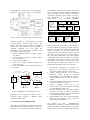
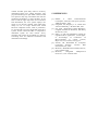
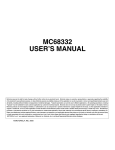
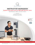
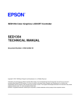
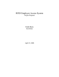
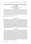
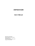
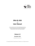
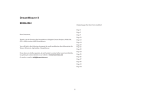
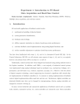
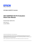
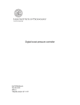
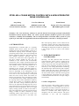
STEEL MILL CRANE MOTION CONTROL WITH A NEW INTEGRATED
DRIVE CONTROLLER
Alojz Slutej
Lars Tuve Hansson
Fetah Kolonić
ABB Ind. Systems AB
ABB Ind. Systems AB
Faculty of El. Eng. and Comp.
S-721 67 Västerås, Sweden
S-721 67 Västerås, Sweden
HR-10000 Zagreb, Croatia
Summary: The steel and heavy industry in general demand increasingly powerful and flexible
Distributed Control Systems (DCS). For cranes special attention should be given to the systems
robustness, reliability and availability. The new Integrated Drive Controller (IDC) system as a part
of DCS for steel mill crane application based on mentioned drive controller is shortly presented.
1. INTRODUCTION
Integrated Drive Controller (IDC) is a specially
designed speed control system for cranes and
another heavy duty material handling systems. It is
intended for slip-ring motors and fully supports
positioning, brake control, rotor step switching and
another application functions. The control system
also includes protective functions that are
necessary for crane motor drives application. Of
the drive systems suitable for this size (201000kW) in this electrical and environmental
situation the stator voltage controlled systems and
slip-ring motors since long has been and still is the
most suitable solution. The energy balance for a
crane drive is normally not considered as
important as the previous mentioned objectives.
The installation cost and hence the suitability are
however depending of the management of the
losses on the crane. For the crane drive that most
of its time is run in full speed up or full speed
down the losses except motors and cables are
about 4% of the motor power. The figure is similar
to the described stator voltage controlled system
for slip-ring motors and a regenerative frequency
inverter drive system or a regenerative DC-drive
system. The stator voltage controlled system has
however the important advantage that the mayor
part of the losses occurs in an external resistor, not
inside the electrical equipment. The cost for high
quality cooling systems on cranes in steel mills is
high. The regeneration of the full speed lowering
energy is based on direct connection by fully
conducting phase control thyristors of the over
synchronously running motor to the mains. The
IDC with slip-ring motors is more robust for the
momentary quality of the line voltage then another
type of AC or DC drive. Of this reason it has been
meaningful to design the new IDC for operation at
a line voltage as low as 75% of the nominal
voltage.
2. INTEGRATED DRIVE
CONTROLLER
Basically, the IDC performs Stator and Rotor
control functions. Stator control is related to the
torque control. Rotor control by optimizing the
resistance gives the motor the right characteristics.
The new drive minimizes the stator current and
sensitivity to line voltage fluctuations considering
the required torque. When lowering with a slightly
higher speed then the motors synchronous, the
motor will regenerate the energy back to the line in
the most robust manner. Then the lowering speed
is approaching the synchronous, the rotor resistor
is minimized and the direction of torque changes
electronically.
2.1. IDC configuration
The drive system, both control system as well as
power electronics, is made adaptable to meet all
requirements of today's and future crane drives in
steel production (Fig.1). The power electronics is
made in a modular form which supports the
integration into the cranes structure. The space
requirement is low, and the temperature
withstandability is high. The Control module is
generating the firing pulses to the thyristors
the MC68010, MC68020 and is binary and source
code compatible with the Motorola MC68000family. The control board comprises a number of
connectors interfacing other boards or devices.
The MC68332 is a 32-bit integrated
microcontroller
with
powerful peripheral
Measurement:
Line Voltage
Stator Current
Rotor Frequency
Local Diagnostic:
2x 7'th segment
Display
Control:
Firing pulse unit
Bridge change log.
TPU
Back
UP
Power Supply:
24Vin, 5V,+/-15V
Supervision:
QSM
MC68332
RWM
fPROM
QSP
Data Bus
Address Bus
Control Bus
Fig.1. Structure of integrated drive controller (IDC)
module by means of a conventional wire, which
limits the distance between these units to a few
meters. All control system connections are made by
optical fiber. The interfaces can be installed to
optimize installation cost and reduce the
interference. The commercially available standalone system consists of (Fig.2):
• Thyristor Module Max 600 V Mains voltage,
25 - 2000 A
• Control module - Thyristor module. (Cable
max. length L=2m)
• Control system module
• Process I/O module (Control module and
process I/O unit)
• Cabin I/O module (Control module and cabin
I/O unit))
Overriding control system
Master -Follower drive control module
Cabin I/O Module
Line
Control Module
Operators Console #2
Thyristor
Module
115 /
230 VAC
Process I/O Module
Motor
Process information, Actuators
Cabin I/O Module
Operators Console #1
Fig. 2. Configuration of stand-alone version
Optionally a rotor frequency evaluation unit is
available, which replaces a hardware pulse
transmitter on the motor.
2.2. Control system module design
The control system module is built up around the
Motorola MC68332 microcontroller unit, (Fig. 3).
The CPU core of the microcontroller is based on
Host Comm:
DDCS Prot.
Opto Link plastic
4MBaud
Service Comm:
DCB Prot.
RS 232
9.6 KBaud
P I/O Comm:
FIELD Bus Prot.
Opto Link Glass
2MBaud
CMT Comm:
DDCS Prot.
Opto Link plastic
4MBaud
Fig.3.Control system module block diagram
subsystems [6]. MCU is based on the MC68020,
the CPU instruction processing module utilize the
extensive software based for the Motorola MC68k
family. It includes an external interface and
various functions that reduce the need for external
glue logic (2 chip select lines, system protection,
test, and clock submodule). The CPU module
configuration registers allows the user to configure
and monitor the system according to the system
requirements. The system is set up by the local
operating system software after a power on reset.
Following monitoring functions are supported:
• Halt Monitor, responds to an assertion on
HALT_N on the internal bus. HALT_N is
asserted if a double bus fault is generated.
• Spurious Interrupt Monitor. If no interrupt
arbitration occurs during an interrupt
acknowledged cycle the BERR_N signal is
asserted internally, and bus error exception is
started.
• Internal Bus Monitor takes care of the response
time for all internal bus accesses.
• Software watchdog, asserts reset if the
software fails to service the software watchdog
for a designated period of time.
• Periodic Interrupt Timer, generates periodic
interrupts. The timer is used for generating
time scheduler interrupts, and the period time
is set by the application software.
• Reset Handling. The reset exception handling
routines for the different types of reset are
determined by programmer.
The process I/O and
Master/follower
communication interface is a high speed data link
based on the SDLC standard protocol [1]. The PC
based Service Tool can communicate with any
IDC connected to the bus. The PC is connected to
the RS232 interface (9.6 kBit/s) of one IDC and
communication to the other IDC's on the same bus
is easily accomplished. The messages are relayed
back and forth through that one IDC [4].
2.3. Process I/O control module design
The control module for different type of process
I/O units is built up around the Motorola
MC68302 microcontroller unit [7]. The CPU core
of the microcontroller is based on the MC68000.
The control module (Fig.4.) comprises a number
of connectors interfacing other boards or devices:
Control board, another process I/O modules and
service terminal.
the system according to the system requirements.
The main Commmunication Processor (CP) is a
RISC processor that services the three Serial
Communication Channels (SCC). Serial Direct
Memory Access channels are associated with three
full-duplex SCCs. Each channel is permanently
assigned to service the receive or transmit
operation of one of the SCCs and is always
available, regardless of the SCC protocol chosen.
A watchdog timer is used to protect against system
failures by providing a means to escape from
unexpected input conditions, external events or
programming errors. The system is set up by the
local operating system software after a power on
reset.
3. IDC SOFTWARE SUPPORT
The IDC is on line programmable and various
functions and operating modes can be selected by
fixed number of parameters. The motor control
programs are located in the control system
module, which is controlled by either a torque or a
speed reference provided locally ( stand-alone
drive system ) or by the overriding system.
Commissioning and Maintenance Tool (CMT) is
ABB’s new PC based program for IDCs. The
CMT offers the following functions:
Fig.4. Process I/O module
The MC68302 is a 32-bit Integrated
microcontroller
with
powerful
peripheral
subsystems. MCU is based on the MC68000, the
CPU instruction processing module utilize the
extensive software based for the Motorola MC68K
family. The device is especially suitable to
applications in the communications industry for a
wide variety of DCSs. The MC68302 contains an
extensive support that simplifies the job of both
the hardware and software designer. It integrates
the MC68K core with the most common
peripherals used in the well known MC68K base
system. The independent direct memory access
controller relieves the hardware design of the extra
board logic. The interrupt controller can be used in
a dedicated mode to generate interrupt
acknowledge signals without external logic. The
chip select signals and wait state logic are also
totally integrated. The module configuration
registers allows the user to configure and monitor
•
Monitoring of reference and actual values
•
Setting, changing, saving, uploading,
downloading and restoring of parameters
•
Controlling and displaying data loggers
The Process I/O basic software support and
different communication drivers are located in the
control module.
4. CONCLUSION
The crane structure normally results in a certain
distance range between the operator’s cabin and
electrical room. The new Integrated Drive
Controller (IDC) is suitable for this type of
application, as it includes main control module and
different type of remote I/O units. Besides the
standard control features it includes following
improvements: better and full control of the motor
torque down to 70% of incoming line voltage,
better heat endurance, static closed loop feedback
for more accurate speed controller and much better
man machine communication facilities. The drive
controller has no need for manual adjustment to be
able to compromise between the motors torque at
lowest expected line voltage and lowest current at
the nominal voltage. The new true feedback
without movable parts fairly utilize a necessary
information about rotor voltage frequency. The
proposed method gives quite stable values around
zero speed or unity slip, and reduces the need for
mechanical tachometer or pulse encoders. To be
able to find the right ramp times for acceleration
and deceleration, the new system employs the
torque as an internal variable. This means that
ramps are set as torque instead time based
functions. Important cranes, used in production,
are not allowed to stop for single fault in the drive
system. Of this reason the IDC is composed as
individual system for each motion. Every
particular sub-system can be linked in a superior
overriding level for industrial automation and
information interchange.
5. REFERENCES
[1] Halsall,
F.
"Data
Communications
Commputer Networks and Open Systems",
Addison-Wesley, 1992.
[2] Fitzgerald, A.E, Kingsley C. Jr, Umans S.D.
"Electric Machinery", McGraw Hill, 1991.
[3] Say, M.G. "Alternating Current Machines",
Longman Scientific & Technical, John Wiley
& Sons Inc, 1983.
[4] Slutej, A. "The new Multidrive concept for
engineered drive application", invited paper,
in
Proceedings
of
Conference
on
Microcomputers
in
control
systems,
Mipro’94, vol.2, Croatia, 1994, pp1-5.
[5] Åstrom, J.K, Wittenmark B. "Computer
Controlled
Systems",
Prentice
Hall
International, Inc, 1984.
[6] Motorola, "Embeded Control Family 68332",
User’s manual 1995.
[7] Motorola,
"Integrated
Multiprotocol
Processor ", User’s manual 1991.