1
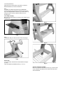
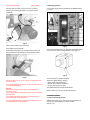
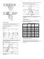
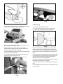
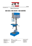
4224B
WOOD LATHE
Original:
GB
Operating Instructions
Translations:
D
Gebrauchsanleitung
F
Mode d´emploi
Walter Meier (Tool) AG
Tämperlistrasse 5
CH-8117 Fällanden
Switzerland
Phone
+41 44 806 47 48
Fax
+41 44 806 47 58
[email protected]
www.jettools.com
M-1794224BM
2012-11-21
CE-Conformity Declaration
Product: Wood Lathe
4224B
Stock Number: 1794224BM
Brand: JET
Manufacturer:
Walter Meier (Tool) AG, Tämperlistrasse 5, CH-8117 Fällanden, Switzerland
On our own responsibility we hereby declare that this product complies
with the regulations
* 2006/42/EC
* 2004/108/EC
* 2006/95/EC
* 2002/95/EC
Machinery Directive
EMC Directive (Electro Magnetic Compatibility)
Low Voltage Directive
RoHS Directive (Reduction of Hazardous Substances)
designed in consideration of the standards
** EN ISO 12100-1, EN ISO 12100-2, EN ISO 13857, EN 349, EN 953,
EN 60204-1, EN ISO 11202, EN 61000-6-4, EN 61800-3, EN 55011, EN 55014-2, EN ISO 14121-1
Technical file compiled by: Hansjörg Brunner, Product Management
2012-11-21
Eduard Schärer, General Manager
Walter Meier (Tool) AG, Tämperlistrasse 5, CH-8117 Fällanden, Switzerland
2
GB - ENGLISH
Operating Instructions
Dear Customer,
Many thanks for the confidence you have shown in us with the purchase of your new JET-machine. This manual has been
prepared for the owner and operators of a JET 4224B wood lathe to promote safety during installation, operation and
maintenance procedures. Please read and understand the information contained in these operating instructions and the
accompanying documents. To obtain maximum life and efficiency from your machine, and to use the machine safely, read this
manual thoroughly and follow instructions carefully.
…Table of Contents
1. Declaration of conformity
1. Declaration of conformity
On our own responsibility we hereby declare that this product
complies with the regulations* listed on page 2. Designed in
consideration with the standards**.
2. Warranty
3. Safety
Authorized use
General safety notes
Remaining hazards
4. Machine specifications
Machine description
Technical data
Noise emission
Contents of delivery
5. Transport and start up
Transport and installation
Assembly
Mains connection
Dust collection
Compressed air connection
Starting operation
6. Machine operation
Correct operating position
Tool selection
Speed selection
Turning between centres
Bowl turning
Sanding and Finishing
7. Setup and adjustments
Changing spindle speeds
Headstock spindle lock
Headstock spindle index
Installing work holding
Adjusting tool rest
Adjusting tailstock
Installing bed extension
Installing bed extension kit
2. Warranty
The Seller guarantees that the supplied product is free from
material defects and manufacturing faults. This warranty does
not cover any defects which are caused, either directly or
indirectly, by incorrect use, carelessness, accidental damage,
repair, inadequate maintenance or cleaning and normal wear
and tear.
Guarantee and/or warranty claims must be made within
twelve months from the date of purchase (date of invoice).
Any further claims shall be excluded.
This warranty includes all guarantee obligations of the Seller
and replaces all previous declarations and agreements
concerning warranties.
The warranty period is valid for eight hours of daily use. If this
is exceeded, the warranty period shall be reduced in
proportion to the excess use, but to no less than three
months.
Returning rejected goods requires the prior express consent
of the Seller and is at the Buyer’s risk and expense.
Further warranty details can be found in the General Terms
and Conditions (GTC). The GTC can be viewed at
www.jettools.com or can be sent by post upon request.
The Seller reserves the right to make changes to the product
and accessories at any time.
3. Safety
3.1 Authorized use
8. Maintenance and inspection
Adjusting bed clamping
Changing belt and bearings
This wood lathe is designed for turning wood only. Machining
of other materials is not permitted and may be carried out in
specific cases only after consulting with the manufacturer.
9. Trouble shooting
The workpiece must allow to safely be loaded and supported.
10. Environmental protection
The proper use also includes compliance with the operating
and maintenance instructions given in this manual.
11. Available accessories
The machine must be operated only by persons familiar with
its operation and maintenance and who are familiar with its
hazards.
The required minimum age must be observed.
The machine must only be used in a technically perfect
condition.
When working on the machine, all safety mechanisms and
covers must be mounted.
In addition to the safety requirements contained in these
operating instructions and your country’s applicable
regulations, you should observe the generally recognized
technical rules concerning the operation of woodworking
machines.
Any other use exceeds authorization.
In the event of unauthorized use of the machine, the
manufacturer renounces all liability and the responsibility is
transferred exclusively to the operator
Keep children and visitors a safe distance from the work area.
Do not operate the electric tool near inflammable liquids or
gases. Observe the fire fighting and fire alert options, for
example the fire extinguisher operation and place.
Do not use the machine in a dump environment and do not
expose it to rain or direct sunlight.
Wood dust is explosive and can also represent a risk to
health. Dust form some tropical woods in particular, and from
hardwoods like beach and oak, is classified as a carcinogenic
substance. Always use a suitable dust collection device
Before machining, remove any nails and other foreign bodies
from the workpiece.
3.2 General safety notes
Woodworking machines can be dangerous if not used
properly. Therefore the appropriate general technical rules as
well as the following notes must be observed.
Make sure to guide and hold the chisel with both hands safe
and tight during machining.
Work only with well sharpened tools.
Read and understand the entire instruction manual before
attempting assembly or operation.
Machine only stock which is chucked securely on the
machine, always check before switching the machine on.
Keep this operating instruction close by the machine,
protected from dirt and humidity, and pass it over to the new
owner if you part with the tool.
Continuous compressed air supply must be assured for
vacuum chucking.
The chucking surface must be big enough to ensure sufficient
vacuum forces.
The workpiece must be homogenous and thick enough to
avoid air leakage and pressure loss.
No changes to the machine may be made.
Daily inspect the function and existence of the safety
appliances before you start the machine.
Do not attempt operation in this case, protect the machine by
unplugging the mains cable.
If reversing spindle rotation, make sure face plate or vacuum
chuck is secured with the set screws.
Remove all loose clothing and confine long hair.
Provide workpieces with centre holes before clamping
between centres.
Before operating the machine, remove tie, rings, watches,
other jewellery, and roll up sleeves above the elbows.
Work large and unbalanced workpieces at low spindle speed
only.
Wear safety shoes, never wear leisure shoes or sandals.
When sanding, remove the tool rest from the machine.
Always wear the approved working outfit.
Workpieces with cracks may not be used.
Do not wear gloves.
Remove the chuck key or dowel pins before turning the
machine on.
Wear goggles when working
Install the machine so that there is sufficient space for safe
operation and workpiece handling.
Keep work area well lighted.
Always close the belt cover.
Specifications regarding the maximum or minimum size of the
workpiece must be observed.
The machine is designed to operate in closed rooms and
must be placed stable on firm and levelled table surface.
Test each set-up by revolving the work by hand to insure it
clears the tool rest and bed. Check setup at the lowest speed
before you increase to the operating speed.
Make sure that the power cord does not impede work and
cause people to trip.
Do not remove chips and workpiece parts until the machine is
at a standstill.
Keep the floor around the machine clean and free of scrap
material, oil and grease.
Never stop work pieces with the hand during run out.
Stay alert! Give your work undivided attention. Use common
sense. Do not operate the machine when you are tired.
Keep an ergonomic body position.
Maintain a balanced stance at all times.
Do not operate the machine under the influence of drugs,
alcohol or any medication. Be aware that medication can
change your behaviour.
Never reach into the machine while it is operating or running
down.
Never leave a running machine unattended. Before you leave
the workplace switch off the machine.
Do not attempt to engage the spindle lock pin until the spindle
has stopped.
Never take measurements on a rotating workpiece.
Do not stand on the machine.
Do not obstrukt the air flow on heat sinks of AC-drive (allow
natural cooling).
Connection and repair work on the electrical installation may
be carried out by a qualified electrician only.
(Warning: Wait five minutes for DC-bus capacitors discharge
before accessing the AC drive unit.)
Have a damaged or worn power cord replaced immediately.
Make all machine adjustments or maintenance with the
machine unplugged from the power source.
3.3 Remaining hazards
When using the machine according to regulations some
remaining hazards may still exist.
The rotating workpiece can cause injury.
Workpieces that are inhomogeneous or weak can explode
when being processed due to centrifugal force.
Only process selected woods without defects.
Unbalanced workpieces can be hazardous.
I 350mm toolrest
J Comparator support
K Live centre
L Tailstock with laser etched scale
M Tailstock with storage cavity
N Tailstock handwheel
O Powerful 3 horsepower motor
P Tool caddy with tools
Q Front-mounted controls
R Integrated vacuum system
S Remote control
T Heavy cast iron bed with precision ways
U Cast iron legs
V Ledges for shelf support
W Leveling feet
Loss off compressed air supply can be hazardous.
Injuries can occur when feeding tooling, if tool supports are
not correctly adjusted or if turning tools are blunt.
Risk of kickback. The tooling is caught by the rotating
workpiece and thrown back to the operator.
Thrown workpieces and workpiece parts can lead to injury.
Dust and noise can be health hazards. Be sure to wear
personal protection gear such as safety goggles and dust
mask. Use a suitable dust collection system.
The use of incorrect mains supply or a damaged power cord
can lead to injuries caused by electricity.
4. Machine specifications
4.1 Machine description
4.2 Technical data
Swing over bed
610mm
Swing over tool rest base
490mm
Centre distance
1067mm
Number of mechanical speeds
3
Spindle speed range L
0 - 910 rpm
Spindle speed range M
0 - 2000 rpm
Spindle speed range H
0 - 3500 rpm
Spindle nose
M33x3,5 DIN 800
Headstock spindle taper
MT 2
Spindle index lock
14x25.7°, 36x10°, 48x7.5°
Spindle hole diameter
15,8mm
Tailstock spindle taper
MT 2
Tailstock hole diameter
9,5mm
Tailstock ram travel
115mm
Centre above floor
1120mm
Overall (LxWxH)
Leg footprint (LxW)
Net weight
Mains
Output power
Reference current
Extension cord (H07RN-F):
Installation fuse protection
Isolation class
Compressed air supply
2260x710x1651mm
1600x610mm
395 kg
1~230V, PE, 50Hz
2,2 kW (3 HP) S1
12 A
3x1,5mm²
16A
I
6,5bar ( 90psi)
4.3 Noise emission
Acoustic pressure level
(EN ISO 11202):
Idling
In operation
Fig 1
A
B
C
D
E
F
G
H
Vacuum connection
98-position indexing system
Spindle lock
Sliding headstock
Belt drive access door
Digital read out
Vaccum chuck
Guard
LpA 72,5 dB(A)
LpA 78,4 dB(A)
The specified values are emission levels and are not
necessarily to be seen as safe operating levels.
As workplace conditions vary, this information is intended to
allow the user to make a better estimation of the hazards and
risks involved only.
4.4 Content of delivery
Casting legs with levelling pads
350 mm tool rest
75 mm face plate
Spur centre and tooling knockout bar
Live centre
Guard
Comparator centres
Tool caddy
Vacuum adaptor and support bracket
Vacuum chuck
Air blow gun with house
Remote ON/OFF switch
Operating tools
Assembly kit
Operating manual
Spare parts list.
Dispose of the packing in an environmentally friendly manner.
Clean all rust protected surfaces with a mild solvent.
Attach the leg stand:
At this point the headstock, tailstock and tool rest should be
removed.
The machine is heavy! Get the help of a second person.
Loosen both headstock cams (A, Fig 3) with provided wrench
to position the head along the lathe bed.
Fig 3
Remove the stop pin (B) to slide the headstock off the bed.
Carefully turn bed upside down on skid. Make sure nothing is
beneath that would scratch the bed ways. Prevent damage to
the JET-Logo plate.
Attach the leg stand with 8 hex socket cap screws, lock
washers and flat washers (A, Fig 4-1).
Fig 2
5. Transport and start up
Fig 4-1
Install leveling feet and tighten nuts against the leg (Fig 4-2).
5.1 Transport and installation
The machine is designed to operate in closed rooms and
must be placed stable on firm and levelled ground.
The machine can be bolted down if required.
For packing reasons the machine is not completely
assembled
5.2 Assembly
If you notice transport damage while unpacking, notify your
supplier immediately. Do not operate the machine!
Fig 4-2
Turn bed upside down.
Adjust the feet so that the lathe rests evenly on the floor.
Reinstall headstock, tool rest and tailstock.
Note:
If installing the 508mm bed extension Kit (#6294900E,
optional), the right leg and bed end surfaces must be flush.
If you are bolting the lathe to the floor, you need to block up
the legs by 40mm to allow sufficient clearance for the
elevating post.
Tool caddy assembly:
Mount the tool caddy with two screws and lock washers to the
left leg (Fig 5)
Fig 7-1
Fig 5
Note:
The tailstock body can also be used to store tools (Fig 6).
Fig 7-2
Fig 6
Stand shelf:
You can install an extra shelf that rests between the legs if
you wish.
There are different possibilities (see Fig 7-1 to 7-3).
Fig 7-3
Optical comparator assembly:
Mount the comparator brackets (C and D, Fig 10) to the back
of the headstock and tailstock with socket head cap screws
and lock washers.
Fig 11
Fig 8
The tailstock bracket has elongated holes, so it can be
aligned with the headstock bracket.
There are two detents that will hold the guard in place.
One is for turning and the other is for when you need the
guard up and out of the way.
The comparator allows to hold a sample workpiece for optical
reference and comparative measurement taking.
( see Fig 9-10).
Tighten the bushings (B) against the bracket with two set
screws (C).
Fig 12
Fig 9
5.3 Mains connection
Mains connection and any extension cords used must comply
with applicable regulations.
The mains voltage must comply with the information on the
machine licence plate.
The mains connection must have a
16 A surge-proof fuse.
Only use power cords marked H07RN-F
Connections and repairs to the electrical equipment may only
be carried out by qualified electricians.
5.4 Dust collection
Fig 10
Guard assembly:
Attach the guard to the bracket by inserting the rod and lifting
up on the plunger (A, Fig 11).
Use a suitable dust collection and air filtration system to avoid
high dust concentrations in the air.
5.5 Compressed air connection
To use the vacuum chuck and the blow gun, the machine
must be connected to compressed air.
Compressed air supply
6,5bar ( 90psi)
Connect blow gun hose (A, Fig 13) to the T-connector.
Connect your incoming air supply to the quick connect
coupler (B).
5.6 Starting operation
You can start the machine by pulling the red ON/OFF button
(I, Fig 15).
Fig 13
Attach vacuum adaptor (C) to hose (D).
Push adaptor into the spindle.
Install support bracket (E, Fig 14) with knurled screw. This
prevents adaptor from backing out during spindle rotation.
Fig 15
The machine will stop when you push the red ON/OFF button
(I, Fig 15) or the remote control ON/OFF button (Fig 16).
Fig 16
Fig 14
Rotate the switch (H, Fig 15) to activate or to deactivate the
vacuum air flow .
The vacuum gauge (R) shows the vacuum pressure achieved
in cmHg (80cmHg=1bar).
Turn the knob (K) to the desired RPM.
There are 3 speed ranges, offering
-“speed” (high range 0-3500 rpm)
-”general use” (medium 0-2000 rpm)
- “torque” (low range 0-970 rpm).
Caution:
Continuous compressed air supply must be assured for
vacuum chucking.
The chucking surface must be big enough to ensure sufficient
vacuum forces.
The workpiece must be homogenous and thick enough to
avoid air leakage and pressure loss.
The RPM Readout shows the spindle speed
If reversing spindle rotation, make sure face plate or vacuum
chuck is secured with the set screws.
Always support the tool on the tool rest and guide with the
palm of your hand keeping your fingers closed.
(see Fig. 18 )
Use the switch (J) to reverse the spindle direction.
6. Machine operation
6.1 Correct operating position
Skew Chisel (C, Fig 19), used to make vees, beads, etc. (Fig
21). The bevel of scew is parallel to the cut.
Fig 21
Parting tool (D, Fig 19), used to cut directly into the material,
or to make a cut off. Also used for scraping and to set
diameters.
6.3 Speed selection:
Fig 18
6.2 Tool selection
Successful wood turning does not result from high speeds,
but rather, from the correct use of turning tools.
A perfect and sharp wood turner tool is a precondition for
professional wood-turning.
Major tools:
Fig 19
Gouge (A, Fig 19), used for rapidly cut raw wood into round
stock, for turning bowls and plates, for turning beds, coves
and other detail (Fig 20).
Fig 20
Scraper (B, Fig 19), used for diameter scraping and to
reduce ridges.
Use low speeds for roughing and for large diameter work. If
vibrations occur, stop the machine and correct the cause.
See speed recommendations.
Speed recommendations
Workpiece
Diameter
mm
Roughing
RPM
General
Cutting
RPM
Finishing
RPM
< 50
1500
3200
3500
50-100
700
1600
2500
100-150
500
1100
1600
150-200
370
800
1200
200-250
300
650
1000
250-300
250
500
800
300-350
220
450
700
350-400
180
400
600
6.4 Turning between centres
With a ruler locate and mark the centre on each end.
Put a dimple in each end of the shock. Extremely hard woods
may require kerfs cut into the spur drive end of stock
(see Fig 21).
Fig 24
Fig 21
The spur drive centre locks into the cleaned spindle taper and
can be removed with the knockout rod (Fig 22)
6.5 Bowl turning
Turn outside of bowl between centres.
Turn a short tenon the size of the hole in the faceplate
(A, Fig 25). This will allow centring the workpiece.
Fig 22
Mount the centred workpiece between the spur drive centre
and the tailstock mounted live centre
Turn the tailstock hand wheel until the live centre well
penetrates the workpiece. Reverse the hand wheel by one
quarter turn and lock the tailstock spindle.
Turn the workpiece by hand to see if it rests securely between
centres and can be rotated freely.
For turning between centres the tool rest is set appr. 3mm
higher than centre line (Fig 23 and 24).
Fig 25
Mount the workpiece (A, Fig 26) directly to the face plate
using 4 wood screws (C) from the back. Be careful to use
screws short enough not to interfere with the cutting process
but long enough to hold the workpiece securely to the face
plate.
If screw mounting is not allowed at all, the work may be glued
to a backing block (D) and the backing block screwed to the
face plate. A piece of paper in the glue joint will prevent
damaging the wood when separated later.
Mount the face plate with the workpiece already attached onto
the spindle nose thread and hand tighten.
Move tailstock away, remove centre from tailstock to prevent
injury.
Turn the workpiece by hand to see if it rests securely and can
be rotated freely.
Fig 23
7. Setup and adjustments
General note:
Setup and adjustment work may only be carried out after
the machine is protected against accidental starting by
pulling the mains plug.
7.1 Changing speed range
Disconnect the machine from the power source!
Loosen the locking screw and open the belt cover.
Loosen the locking handle (A, Fig 28).
Fig 26
For face plate turning the tool rest is set slightly lower than
centre line.
Caution:
Cut with your chisel on the left side of the turning centre only.
Use left hand to control cutting edge of gouge, while right
hand swings tool handle around toward your body (Fig 27).
Fig 28
Lift up on the tensioning handle (B) to remove tension from
the poly v-belt.
You can now position the belt in the desired speed range.
Note:
“High” speed range (0 - 3500 rpm) for maximum speed.
Fig 27
“Medium” speed range (0 - 2000 rpm) for general use
Try to make one, very light continuous movement from the rim
to the bottom of the bowl to ensure a clean, sweeping curve
through the workpiece.
“Low” speed range (0 - 910 rpm) for maximum torque.
Move tool support to the exterior to re-define bottom of bowl.
6.6 Sanding and Finishing
Remove the toolrest and begin with a fine grit sandpaper (120
grit) and progress through each grit, using only light pressure.
Use power sanding techniques to avoid concentric sanding
marks.
Finish sanding with 220 grit.
Apply first coat of finish. Allow to dry before sanding again
with 320 or 400 grit sandpaper.
Turn lathe back on and make a separation cut through the
base. Stop at about dia. 80mm and use a fine tooth saw to
separate the bowl from the waste.
Apply additional finish coats and allow to dry before buffing.
Lower the tensioning handle so that the weight of the motor
provides the needed tension and tighten the locking handle.
Close and lock the belt cover.
Warning:
The AC Inverter does not require any programming. It is preprogrammed from the factory. The buttons and knob on the
inverter should not be changed.
7.2 Headstock spindle lock
Push in pin (G, Fig 29) to stop the spindle from turning.
Slide down the bracket (F) to hold in place.
7.4 Installing work holding
The faceplate is used for tuning bowls. There are a number
of holes for mounting the workpiece.
Thread the faceplate onto the spindle in a clockwise direction,
and tighten two set screws (E, Fig 31).
Fig 29
Caution:
Never press the spindle lock while the spindle is turning!
7.3 Headstock spindle index
The handwheel has 3 arrays of holes
14x25.7°, 36x10°, 48x7.5°
The spindle nose has a matching graduation scale.
Fig 31
Remove the faceplate by loosening two set screws (E).
Push in the spindle lock and use the provided open spanner
(F, Fig 32).
Loosen handle (A, Fig 30) and position bracket until indexer
pin aligns with the desired array of holes.
Fig 30
Rotate spindle by observing the spindle graduation.
Push indexer pin to engage the handwheel hole.
Screw in indexer knob to hold in place.
Caution:
Do not overtighten the indexer knob, to avoid deflection.
Release index pin before turning on the lathe.
Never press the index pin while the spindle is turning!
The indexer assembly can be removed from the lathe by
unscrewing locking handle (A).
Fig 32
Caution:
If reversing spindle rotation, always make sure face plate or
vacuum chuck is secured with the set screws.
7.5 Adjusting tool rest
Position the tool rest as close to the workpiece as possible.
Tighten handle (C, Fig 33) to lock.
Set the height to approximately 3mm above centre line.
Tighten indexable knob (D).
If tool rest post begins to slip, tighten up the hex socket cap
screw (E).
The centering pin can be knocked out to allow deep hole
drilling operations.
7.7 Installing bed extension (# 6294905E)
Have an assistant hold bed extension flush to end of lathe
bed, and insert four screws with washers (B, Fig 36).
Snug screws just enough to hold bed extension to lathe bed.
Unscrew stop bolt (A) from lathe bed and insert it into hole at
end of bed extension.
Fig 33
7.6 Adjusting tailstock
Turn the hand wheel (P, Fig 34) clockwise to move tailstock
spindle forward. Lock tailstock spindle with the indexable knob
(O).
Fig 36
Top surfaces and inside ways must be flush to allow smooth
movement of tailstockt.
Slide tailstock over joint where beds meet, so that clamping
nut is centered over joint. Lock tailstock clamping handle; this
will align the beds. (Fig 37).
Fig 34
The handle (Q) locks the tailstock in position on the bed.
The live centre can be ejected by turning the hand wheel
counter-clockwise.
To screw off the cone (R, Fig 35) the life center must be
locked against rotation with the supplied pin (S).
Fig 37
Tighten screws in extension bed.
7.8 Installing bed extension kit (# 6294900E)
Fig 35
The machined surfaces of bed end and leg must be aligned
flush.
Use a straight edge to check (Fig 38).
Fig 40
Fig 38
Install bed extension in the same manner as described in
chapter 7.7
Install elevating system to bed extension with four screws and
washers, and to lathe leg with three screws and washers (A,
Fig 39). One screw is installed from inside the leg and
secured with nylon nut (B).
For outboard turning, move the headstock to opposite end of
lathe.
To accommodate large workpieces, you can mount the bed
extension to the lower set of holes, and mount an extension
post [included with kit] to the tool rest base ( Fig 40).
Install handwheel and tighten sets crew.
Fig 39
Note: If heavy loading makes handwheel turning difficult, a
19mm wrench can be used (Fig 40).
Fig 40
For larger outboard work, a heavy outboard turning stand is
available (# 708349).
8. Maintenance and inspection
General notes:
Maintenance, cleaning and repair work may only be
carried out after the machine is protected against
accidental starting by pulling the mains plug.
Clean the machine regularly.
Remove any foreign objects from the heat sinks of AC-drive
(Do not obstruct the air flow).
Inspect the proper function of the dust collection daily.
Defective safety devices must be replaced immediately.
Repair and maintenance work on the electrical system may
only be carried out by a qualified electrician.
(Warning: Wait five minutes for DC-bus capacitors
discharge before accessing the AC drive unit!)
8.1 Adjusting bed clamping
If adjustment is needed, remove the stop bolt on end of bed.
Fig 42
Loosen and remove the clamping nut (B) and lock washer (C).
Use a wood dowel, or aluminium stock to knock spindle
towards the tailstock. (Use a material that is softer than the
spindle so you do not mushroom end of spindle).
Go only far enough to remove the belt from spindle.
Slide the headstock, tailstock or toolrest to the edge of the
bed and slightly turn the hex nut (B; Fig 41).
To reassemble reverse the procedure.
Test the clamping function and repeat if necessary.
When reinstalling clamping nut, thread it on to the spindle until
its snug. Then back off slightly and tighten the lock washer.
Note:
To remove the pulley for bearing replacement it is needed to
loosen the 2 set screws (E, Fig 43).
Fig 41
8.2 Changing belt and bearings
Changing belt and bearings can be a difficult task.
By chance, remove headstock and take into a repair
station for servicing.
Disconnect the machine from the power source.
Open the door and remove the belt from the lower pulley.
Loosen two set screws (A, Fig 42) and unscrew the
handwheel.
Fig 43
Make sure the pulleys are oriented properly after reassembly
for straight belt runnig.
9. Trouble shooting
Motor doesn’t start
*No electricitycheck mains and fuse.
*Defective switch, motor or cordconsult an electrician.
*Overload detected on AC-drive unitwait and restart machine; chose low speed range belt setting
(0-910 rpm) for better torque.
*Insufficient vacuumcheck compressed air supply
check chucking for air leakage
Machine vibrates excessively
*Stand on uneven flooradjust stand for even support.
*Workpiece is not properly centred
Fig 47
*The speed is too high
10. Environmental protection
Stock number 6294903E
Tailstock Riser Block (Fig 48)
Protect the environment.
Your appliance contains valuable materials which can be
recovered or recycled. Please leave it at a specialized
institution.
11. Available accessories
Stock number 6294905E
Bed Extension 508mm (Fig 44)
Fig 48
Stock number 708349
Heavy outboard turning stand (Fig 46)
Fig 44
Stock number 6294900E
Bed Extension Kit 508mm (Fig 45)
Fig 46
Fig 45
Stock number 6294904E
Bed Extension 1600mm with stand (Fig 47)
Stock number 709911
Face plate 75mm M33x3,5mm
Stock number 709921
Face plate 150mm M33x3,5mm
Stock number 709960
Spindle adapter M33x3,5 / 1”x 8TPI
Stock number 709942
Four toothed spur centre MT-2
Stock number 708343K
Drill chuck 13 mm, with tapered mandrell MT-2
Stock number 709960
Spindle adapter M33x3,5 / 1”x 8TPI
Stock number 708332
Face shield
Refer to the JET-Pricelist
for various tools and work holding.