1
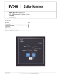
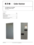
Instruction Booklet IB0162064EN
Effective January 2014
O & M Manual for the EGS Service
Entrance Automatic Transfer Switch
Contents
DescriptionPage
1.Introduction. . . . . . . . . . . . . . . . . . . . . . . . . . . . 2
2.Receiving, Handling, and Storage. . . . . . . . . . . 5
3.Equipment Description. . . . . . . . . . . . . . . . . . . 5
4.Installation and Wiring. . . . . . . . . . . . . . . . . . . . 8
5.Functional Testing. . . . . . . . . . . . . . . . . . . . . . 12
6.Adjustments . . . . . . . . . . . . . . . . . . . . . . . . . . 13
7.Maintenance and Component Replacement . 14
Instruction Booklet IB0162064EN
O & M Manual for the EGS Service
Entrance Automatic Transfer Switch
Effective January 2014
Warning
READ AND UNDERSTAND THE INSTRUCTIONS CONTAINED HEREINAFTER
BEFORE ATTEMPTING TO UNPACK, ASSEMBLE, OPERATE, OR MAINTAIN
THIS EQUIPMENT
HAZARDOUS VOLTAGES ARE PRESENT INSIDE TRANSFER SWITCH
ENCLOSURES THAT CAN CAUSE DEATH OR SEVERE PERSONAL INJURY.
FOLLOW PROPER INSTALLATION, OPERATION, AND MAINTENANCE
PROCEDURES TO AVOID THESE VOLTAGES.
THE TRANSFER SWITCH EQUIPMENT COVERED BY THIS INSTRUCTION
BOOK IS DESIGNED AND TESTED TO OPERATE WITHIN ITS NAMEPLATE
RATINGS. OPERATION OUTSIDE OF THESE RATINGS MAY CAUSE THE
EQUIPMENT TO FAIL RESULTING IN DEATH, SERIOUS BODILY INJURY,
AND/OR PROPERTY DAMAGE. ALL RESPONSIBLE PERSONNEL SHOULD
LOCATE THE DOOR MOUNTED EQUIPMENT RATINGS LABEL AND BE
FAMILIAR WITH THE INFORMATION PROVIDED ON THE LABEL. A TYPICAL
EQUIPMENT RATINGS LABEL IS SHOWN IN FIGURE 1.
Figure 1. Typical Service Entrance Rated Metered Automatic
Transfer Switch Ratings Label.
All possible contingencies that may arise during installation, operation, or maintenance, and all details and variations of this equipment do not purport to be covered by these instructions. If further
information is required by the purchaser regarding a particular installation, application, or maintenance activity, please contact an authorized Eaton sales representative or the installing contractor.
Section 1: Introduction
1.1 Preliminary Comments and Safety Precautions
This technical document is intended to cover most aspects associated with the installation, application, operation, and maintenance
of the Automatic Transfer Switch (ATS). It is provided as a guide for
authorized and qualified personnel only. Please refer to the specific
WARNING and CAUTION in Section 1.1.2 before proceeding. If further information is required by the purchaser regarding a particular
installation, application, or maintenance activity, please contact an
authorized Eaton sales representative or the installing contractor.
1.1.1 Warranty and Liability Information
No warranties, expressed or implied, including warranties of fitness
for a particular purpose of merchantability, or warranties arising from
course of dealing or usage of trade, are made regarding the information, recommendations, and descriptions contained herein. In no
event will Eaton be responsible to the purchaser or user in contract,
in tort (including negligence), strict liability, or otherwise for any special, indirect, incidental or consequential damage, or loss whatsoever, including but not limited to damage or loss of use of equipment,
plant or power system, cost of capital, loss of power, additional
expenses in the use of existing power facilities, or claims against
the purchaser or user by its customers resulting from the use of the
information and descriptions contained herein.
1.1.2 Safety Precautions
All safety codes, standards, and/or regulations must be strictly
observed in the installation, application, operation, and maintenance
of this device.
warning
THE WARNINGS AND CAUTIONS INCLUDED AS PART OF THE
PROCEDURAL STEPS IN THIS DOCUMENT ARE FOR PERSONAL SAFETY
AND PROTECTION OF EQUIPMENT FROM DAMAGE. AN EXAMPLE OF A
TYPICAL WARNING LABEL HEADING IS SHOWN ABOVE TO FAMILIARIZE
PERSONNEL WITH THE STYLE OF PRESENTATION. THIS WILL HELP TO
ENSURE THAT PERSONNEL ARE ALERT TO WARNINGS, WHICH APPEAR
THROUGHOUT THE DOCUMENT. IN ADDITION, CAUTIONS ARE ALL UPPER
CASE AND BOLDFACE.
CAUTION
READ AND UNDERSTAND THE MATERIAL PRESENTED IN THIS DOCUMENT
BEFORE ATTEMPTING INSTALLATION, APPLICATION, OPERATION, OR
MAINTENANCE OF THE EQUIPMENT. IN ADDITION, ONLY QUALIFIED
PERSONS SHOULD BE PERMITTED TO PERFORM ANY WORK ASSOCIATED
WITH THE EQUIPMENT. ANY WIRING INSTRUCTIONS PRESENTED IN THIS
DOCUMENT MUST BE FOLLOWED PRECISELY. FAILURE TO DO SO COULD
CAUSE PERMANENT EQUIPMENT DAMAGE.
2
Eaton Corporation www.eatoncanada.ca
Instruction Booklet IB0162064EN
O & M Manual for the EGS Service
Entrance Automatic Transfer Switch
Effective January 2014
1.2 General Information
1.2.1 Design Configuration
ATSs are used to protect critical electrical loads against loss of
power. The load’s utility power source is backed up by a generator
power source. An ATS is connected to both the utility and generator
power sources and supplies the load with power from one of these
two sources. In the event that power is lost from the utility power
source, the ATS transfers the load to the generator power source.
Once the utility power is restored, the load is automatically transferred back to the utility power source (Figure 2).
The Eaton Service Entrance Rated, Automatic Transfer Switch is
a rugged, compact design that combines a service entrance rated
disconnect, and ATS all in a single enclosure. The design provides
for top entry service cabling from the meter socket. A factory
wired 100 or 200A circuit breaker provides a Canadian approved
service entrance rated disconnect means. The ATS is controlled by
an Eaton RTC-100 controller or relay, and utilizes power contactors
to transfer essential loads from one power source to another
(see Figure 3). The switch’s design uses suitable mechanical and
electrical interlock switches to eliminate the possibility of connecting
the utility service to the generator output. In addition, a manual
override lever is provided for the transfer function.
Generator
Utility
warning
Do not manually transfer THE switch while under load.
Figure 3. EGSCA200ASE (200 A).
Load
Figure 2. Typical Load Transfer Switch (Contactor) Schematic.
An intelligence system initiates the transfer when the utility power
source fails or falls below a preset voltage. An engine start is then
initiated by the ATS or the generator and the ATS transfers to the
generator power source when sufficient generator voltage is available. When the utility power source is restored, the ATS automatically transfers back and the generator will shut down after a time
delay. In the event the utility power source fails and the generator
power source does not appear, the ATS remains connected to the
utility power source until the generator power source does appear.
Conversely, if connected to the generator power source and the
generator power source fails while the utility power source is still
unavailable, the ATS remains connected to the generator power
source.
ATSs automatically perform the transfer function, and include three
basic elements.
1. Main contacts to connect and disconnect the load to and from
the source of power.
2. Solenoids to make the transfer of the main contacts from source
to source.
3. Intelligence/supervisory circuits to constantly monitor the condition of the power sources and thus provide the intelligence necessary for the switch and related circuit operation.
Eaton Corporation www.eatoncanada.ca
3
Instruction Booklet IB0162064EN
O & M Manual for the EGS Service
Entrance Automatic Transfer Switch
Effective January 2014
The benefits of the SE configuration are:
•
Combined service disconnect and over-current protection in the
ATS reduces the overall equipment and installation costs.
•
Fewer components and power connections reduce maintenance
requirements.
1.5 Glossary
With respect to their use within this document and as they relate to
transfer switch and controller operation, the following terminology is
defined.
1.2.3 Load Shed Contacts
Available
Two sets of contacts are available with the transfer switches that
utilize the RTC-100 controller, and can be used to control large connected loads on the generator (i.e. air conditioners, hot tubs, etc.).
The contacts are rated for 250 Vac, 5 amps maximum. This functionality requires that Load monitoring CT’s are installed (sold separately)
Connected
1.3 Transfer Switch Catalogue Number Identification
ATS equipment catalogue numbers provide a significant amount
of relevant information pertaining to a specific piece of equipment.
The Catalogue Number Identification Table (see Table 1) provides the
required interpretation information.
Table 1. ATS Catalogue Numbering System.
E GS
Manufacturer
Eaton
Type
Generator
Switch
C = Relay
CA=RTC100
Failed or Fails
A source is defined as “failed” when it is outside of the applicable
voltage setpoint ranges for the nominal voltage and for a time
exceeding 0.5 seconds after the time delay emergency fail (TDEF)
time delays expires.
Failsafe is a feature that prevents disconnection from the only available power source and also forces a transfer or re-transfer operation
to the only available power source.
Service
Entrance
Ampere
Rating
100 or
200
Connected is defined as when the input is shorted by an external
contact or connection.
Failsafe
CA 200A SE
Transfer
Control
A source is defined as “available” when it is within its undervoltage
setpoint ranges for the nominal voltage setting.
Canadian
Service Entrance
Approved
Re-Transfer
Re-transfer is defined as a change of the load connection from the
Generator to the Utility.
Utility
Utility is the primary source (normal source, normal power source,
or normal).
Generator
1.4 Environmental and Operational Conditions
Normally, an ATS is applied indoors in an electrical equipment room.
It can also be used for normal outdoor applications (with standard
type 3R enclosure) where the equipment is subject to falling rain,
freezing temperatures, and 95% humidity (non-condensing). The
ambient temperature range for operation is between -20 and 70°C
(-4 and 158°F)..
Generator is the secondary source (generator emergency source,
emergency power source, emergency, standby, or backup source).
Utility: Failed or Fails
Utility is defined as “failed” when it is outside of its undervoltage
setpoint ranges for the nominal voltage and frequency setting.
Generator: Failed or Fails
Generator is defined as “failed” when it is outside of its undervoltage/underfrequency/overfrequency (if applicable) setpoint ranges
for the nominal voltage and frequency setting for a time exceeding
0.5 seconds after the Time Delay Emergency Fail (TDEF) time delay
expires.
Transfer
Transfer is defined as a change of the load connection from the
Utility to the Generator power source.
Unconnected
Unconnected is defined as when the input is not shorted by an
external contact or connection.
4
Eaton Corporation www.eatoncanada.ca
O & M Manual for the EGS Service
Entrance Automatic Transfer Switch
Instruction Booklet IB0162064EN
Effective January 2014
Section 2: Receiving, Handling, and
Storage
2.1 Receiving
Every effort is made to ensure that the ATS equipment arrives at
its destination undamaged and ready for installation. The packing is
designed to protect the internal components as well as the enclosure. Care should be exercised, however, to protect the equipment
from impact at all times. Do not remove the protective packaging until the equipment is at the installation site and ready to be
installed.
When the ATS equipment reaches its destination, the customer
should inspect the shipping container for any obvious signs of rough
handling and/or external damage that occurred during transportation. Record any external and internal damage for reporting to the
transportation carrier and to the Eaton sales representative, once a
thorough inspection is complete. All claims should be as specific as
possible and include the Shop Order and General Order numbers.
A shipping label affixed to the shipping container includes a variety
of equipment and customer information, such as General Order and
catalogue numbers. Make certain that this information matches the
other shipping paper information.
Each ATS enclosure is packaged in its own box. Do not discard the
packing material until the equipment is ready for installation.
Once the packaging is removed from the shipment, the enclosure
door can be opened. A plastic bag of documents will be found in
the enclosure. Important documents, such as wiring diagrams and
appropriate instruction leaflets are enclosed within the bag and
should be filed in a safe place.
2.2 Handling
As previously mentioned, ATS equipment is packaged in its own
box. Protect the equipment from impact at all times and do not
double stack. Once the equipment is at the installation site and
ready to be installed, the packaging material can be removed. Refer
to Section 4 of this manual for specific installation instructions.
2.3 Storage
Although well packaged, this equipment is not suitable for outdoor
storage. The equipment warranty will not be applicable if there
is evidence of outdoor storage. If the equipment is to be stored
indoors for any period of time, it should be stored with its protective
packaging material in place. Protect the equipment at all times from
excessive moisture, construction dirt, corrosive conditions, and other
contaminants. It is strongly suggested that the package-protected
equipment be stored in a climate-controlled environment of -20 to
70°C (-4 to 158°F), with a relative humidity of 80% or less. Do not,
under any circumstance, stack other equipment on top of an ATS
equipment enclosure, whether packaged or not.
Eaton Corporation www.eatoncanada.ca
5
Instruction Booklet IB0162064EN
Effective January 2014
O & M Manual for the EGS Service
Entrance Automatic Transfer Switch
Section 3: Equipment Description
3.1 Introduction
The Eaton metered, service entrance rated ATS is assembled and
tested at the factory. It is designed to be used in conjunction with
standby power distribution equipment to provide an alternate source
of power to critical circuits in the event that the primary power
source is interrupted.
The Advanced ATS with RTC100 control monitors both utility and
generator power sources and automatically transfers critical load
circuits between the two sources, depending on which source is
available. The utility power source is preferred and will remain connected to the switch if it is available. The Relay ATS relies on the
Generator Controller to monitor utility and generator power, and signals the relay to control ATS position.
3.2 Service Disconnect
The Service Entrance (SE) section of the ATS is used for making the
primary utility power, and neutral connections. Factory cabling from
the load side of the main circuit breaker service disconnect connects
to the utility lugs of the power contactor assembly.
(Figure 6).
3.2.1 Main Contacts
This ATS incorporates a power contactor. The main contacts connect
and disconnect the load to and from the different power sources.
The power contactor is mechanically and electrically interlocked to
prevent the two sets of main contacts from being closed simultaneously.
Figure 4. Typical Advanced 200 Ampere Interior Assembly.
3.3 RTC-100 Logic Panel on EGSCA100ASE and
EGSCA200ASE
The RTC-100 is a microprocessor-based transfer switch logic control
package. The hardware and software of the controller contain the
intelligence/supervisory circuits that constantly monitor the condition
of the power sources. It provides the intelligence necessary for the
operation of the ATS. Please refer to IB 70-8698 for complete
details.
The RTC-100 controller has an operating temperature of -20 to
70°C (-4 to 158°F).
The controller circuit board is protected by an insulating
conformal coating.
The specifications, under normal operating conditions, are as
follows:
• Tolerance for voltage sensing function: ±1% of full scale
• Tolerance for frequency sensing function: ±0.3 Hz of setting
6
Eaton Corporation www.eatoncanada.ca
Instruction Booklet IB0162064EN
O & M Manual for the EGS Service
Entrance Automatic Transfer Switch
Effective January 2014
Figure 5. Typical Basic 100 Ampere Interior
Assembly.
UC1: Utility Coil 1
UC2: Utility Coil 2
N1: Normal (utility ) 1
N2: Normal (utility) 2
USW: Utlity switch position
GSW: Generator switch position
GC1: Generator coil 1
GC2: Generator coil 2
E1: Emergency line 1
E2: Emergency line 2
L1: Load line 1
L2: Load line 2
F1: Fuse line 1 (used for utility sensing to generator)
F2: Fuse line 2 (used for utility sensing to generator)
REL: Transfer signal Relay
23, 194: Transfer signal connection from generator
Install T1 Fuse Block (provided with generator) in this position, install jumper to L1
or L2 to ensure generator battery is charging
when on utility and on generator source
Eaton Corporation www.eatoncanada.ca
7
Instruction Booklet IB0162064EN
O & M Manual for the EGS Service
Entrance Automatic Transfer Switch
Effective January 2014
4.5 Generator & Load Power Cable Connection
warning
POWER CONDUCTORS MAY HAVE VOLTAGE PRESENT THAT CAN CAUSE
SEVERE PERSONAL INJURY OR DEATH. DE-ENERGIZE ALL POWER
OR CONTROL CIRCUIT CONDUCTORS TO BE CONNECTED TO THE ATS
EQUIPMENT BEFORE BEGINNING TO WORK WITH THE CONDUCTORS AND/
OR TERMINATING THEM TO THE EQUIPMENT
CAUTION
TO HELP PREVENT COMPONENT DAMAGE OR FUTURE MALFUNCTIONS,
USE EXTREME CARE TO KEEP CONTAMINANTS OUT OF THE ATS
EQUIPMENT WHEN MAKING THE POWER CABLE CONNECTIONS.
Test all power cables prior to connection to the unit to ensure that
the conductors or cable insulation has not been damaged while
being pulled into position.
Power cables are to be connected to solderless, screw type lugs
located on the contactor assembly. Verify that the lugs supplied will
accommodate the power cables being used. Also verify that the
cables comply with all local electrical codes. Standard ATS equipment, as supplied from the factory, will accommodate the wire sizes
shown in Table 3.
Table 3. Wire Sizes for ATSs.
Transfer Switch
Amp Rating
Contactor Lug
Size Range
Number of Cables
per Phase
100
#14 - 1/0 AWG
1
200
#4 AWG - 300 MCM
1
Figure 8. Generator & Load Power Cable Connection Locations.
4.6 Wiring
CAUTION
IMPROPER POWER CABLE CONNECTIONS CAN CAUSE EXCESSIVE HEAT
AND SUBSEQUENT EQUIPMENT FAILURE.
NNote: Tighten the cable lugs to the torque identified on the label
affixed to the unit’s door.
WARNING
POWER CONDUCTORS AND control wiring MAY HAVE VOLTAGE
PRESENT THAT CAN CAUSE SEVERE PERSONAL INJURY OR DEATH.
DE-ENERGIZE ALL POWER OR CONTROL CIRCUIT CONDUCTORS BEFORE
BEGINNING TO PERFORM ANY WIRING ACTIVITY TO OR WITHIN THE ATS
EQUIPMENT.
Connect cables as follows (see Figure 10, and Table 3):
•
The generator power cables to the generator lugs on the contactor assembly.
•
The load power cables to the load lugs on the contactor assembly.
•
The generator neutral cable to the generator neutral lug on the
neutral bar assembly.
•
The load neutral cable to the load neutral lug on the neutral bar
asssembly.
•
The generator and load ground cable to the generator and load
ground lugs on the ground bar assembly.
Warning
Failure to properly connect this transfer switch per NFPA 70,
the national electric code, may result in product failure, fire,
loss of property, loss of life, ETc.
8
Eaton Corporation www.eatoncanada.ca
CAUTION
CHECK THE ATS EQUIPMENT NAMEPLATE FOR RATED VOLTAGE. IT
SHOULD BE THE SAME AS THE UTILITY AND GENERATOR LINE VOLTAGES.
OPERATING THE EQUIPMENT ON IMPROPER VOLTAGE CAN CAUSE
EQUIPMENT DAMAGE.
Instruction Booklet IB0162064EN
O & M Manual for the EGS Service
Entrance Automatic Transfer Switch
Effective January 2014
4.7 Installation
4.9 Protection
In a typical installation (see Figure 11), the generator (2) and utility
power connect to the ATS (1). Power from the utility or the gnerator (2) is fed to the main circuit breaker panel from the ATS (1). The
circuit breaker in the ATS is the service entrance disconnect for the
installation.
For Catalogue #EGSC100ASE, EGSCA100ASE, EGSC200ASE and
EGSCA200ASE
When the utility power fails, the ATS will sense the failure, the generator will start, and when sufficient generator voltage is available,
the ATS will switch. All loads will receive power from the generator.
When utility power returns, the ATS will switch all power back to
the utility source and the generator will shut down after its defined
cooled down period.
This switch is equipped with integral over-current protection.
Continuous load current not to exceed 80 percent of switch rating.
This Transfer Switch is rated for use on a circuit capable of delivering not more than 10,000 rms symmetrical amperes, 240 volts maximum.
Section 5: Functional Testing
WARNING
4.7 Generator Start Connection
The generator start contact connection terminal blocks are located
on the RTC100 controller.
NNote: Prior to making the generator start connection to the ATS, set the generator
control selector switch to the OFF position to prevent an unwanted generator start.
Control wiring, such as the generator start wires, must be run in a separate conduit
from the power cables.
A normally open and normally closed contact as well as a common
from the RTC-100 control board are wired out to this set of terminal
blocks. The RTC-100 controller initiates the start
of the generator
by closing or opening these contacts. The start signal requirements
of the generator will determine which contact is used to control the
start up. Use the proper wire size as listed by the generator set
(Genset) manufacturer
4.8 Preliminary Checks
After the ATS enclosure is installed and power cables are connected
to the equipment, thoroughly inspect the unit to ensure that no
tools were left inside and that the cabinet is free of debris. If necessary, use a vacuum cleaner to remove any and all construction or
installation debris from the equipment.
Read and understand all labels on the equipment. Review and
understand the wiring diagrams supplied with the equipment. Note
any optional accessories that may have been furnished with this unit
and review their operation.
Verify that the phase-to-phase line voltages of both the utility and
generator power sources are the same and that they match the
rated voltage as indicated on the ATS ratings label.
CAUTION
SEVERE EQUIPMENT DAMAGE CAN RESULT IF THE UNIT IS NOT APPLIED
AT PROPER VOLTAGE. DO NOT ENERGIZE THE EQUIPMENT IF THE SUPPLY
VOLTAGES DO NOT MATCH EQUIPMENT RATINGS LABEL.
YOU ARE READY TO ENERGIZE THE EQUIPMENT. VOLTAGES WITHIN THE
ENCLOSURE ARE CAPABLE OF CAUSING SEVERE PERSONAL INJURY OR
DEATH. USE EXTREME CAUTION TO AVOID CONTACT WITH ENERGIZED
EQUIPMENT.
5.1 Preliminary Checks
Step 1: Check all loads connected to the ATS to ensure that they are
ready to be energized.
5.2 Energize the Switch
Step 1: With the service entrance barrier removed use a voltmeter to
measure the line-to-line and the line-to-neutral voltages on the
line side of the circuit breaker. Confirm the utility voltage is correct then replace the service entrance barrier.
Step 2: Ensure the generator control selector switch located on the
standby generator is set to the OFF position. If so equiped,
remove the control fuse from the generator control panel to
ensure the generator does not iniate a start during this phase of
the preliminary check. Open the generator power source circuit
breaker located on the generator assembly.
Step 3: Close the service entrance disconnect circuit breaker in the
switch to connect the ATS to the utility power source voltage.
If the ATS unit is not already in the UTILITY position, and the
voltage is acceptable, the solenoid will engage and the contactor will automatically switch to the UTILITY position.
WARNING
CONTACT WITH ENERGIZED COMPONENTS WILL CAUSE ELECTRICAL
SHOCK CAPABLE OF PRODUCING SEVERE PERSONAL INJURY OR
DEATH. USE EXTREME CAUTION TO AVOID CONTACT WITH ENERGIZED
COMPONENTS WHEN USING A METER FOR VOLTAGE CHECKS.
Step 4: Replace the control fuse in the generator control panel removed
in Step 2 of Section 5.2. Position the generator control selector
switch, located on the standby generator, to the AUTOSTART
position. (It may also be labeled REMOTE START or AUTO.).
Close the generator power source circuit breaker opened in
Step 2 of Section 5.2.
Eaton Corporation www.eatoncanada.ca
9
Instruction Booklet IB0162064EN
Effective January 2014
5.3 Operational Checks
Step 1: Open the service entrance disconnect circuit breaker originally
closed in Step 3 of Section 5.2.
NOTICE
This will simulate an interruption of the utility power source.
Step 2: After a time delay (based on the generator settings), the standby
generator engine will start.
Step 3: Using a voltmeter, measure the line-to-line and line-to-neutral
voltages across the generator line terminals to ensure that the
generator emergency voltage is correct. If necessary, make
adjustments to the voltage regulator on the generator according
to the manufacturer’s recommendations to correct any voltage
deviations. The ATS will only respond to the correct voltage
from the generator power source.
Step 4: The ATS Time Delay Normal (Utility) to Emergency (Generator)
(TDNE) will begin to time after the generator engine begins to
run. After time out, the solenoid will engage and the contactor
will automatically switch from the UTILITY to the GENERATOR
position.
Step 5: Close the service entrance disconnect circuit breaker described in
Step 3 of Section 5.2.
Step 7: The ATS Time Delay Emergency (Generator) to Normal (Utility)
(TDEN) timer will begin timing, and the solenoid will engage
and automatically switch from the GENERATOR to the UTILITY
position and the generator will shut down after a cool down
period.
10
Eaton Corporation www.eatoncanada.ca
O & M Manual for the EGS Service
Entrance Automatic Transfer Switch
Instruction Booklet IB0162064EN
O & M Manual for the EGS Service
Entrance Automatic Transfer Switch
Effective January 2014
5.4 Manual Operation
Section 6: Adjustments
warning
DO NOT ATTEMPT TO MANUALLY OPERATE THE ATS WITH the utility
OR generator AVAILABLE.
6.1 General
Refer to IB01602019E, supplied with the ATS for ATC-100 Controller
adjustments and programming.
warning
HIGH VOLTAGES ARE PRESENT IN AND AROUND TRANSFER SWITCH
EQUIPMENT. BEFORE ATTEMPTING TO MANUALLY TRANSFER,
DISCONNECT THE LINE POWER FROM THE EQUIPMENT BEING SERVICED
BY OPENING AND LOCKING OUT, IF POSSIBLE, THE NEXT HIGHEST
DISCONNECT DEVICE. FAILURE TO FOLLOW THIS PROCEDURE COULD
CAUSE SEVERE PERSONAL INJURY AND/OR DEATH.
ALWAYS TURN THE utility POWER OFF AND TURN THE generator (IF
A GENERATOR) CONTROL SELECTOR SWITCH TO THE “oFF” POSITION
BEFORE ATTEMPTING A MANUAL TRANSFER.
warning
InsurE THE DEADFRONT IS INSTALLED PRIOR TO energizing the
TRANSFER SWITCH.
To Manually Operate
Step 1: Disconnect all sources of power.
Step 2: Disconnect the J7 connector from the ATC-100 controller.
Step 3: Locate the manual lever between the solenoids..
Step 4: Locate the handle used to manually transfer the switch.
Step 5: Attach the handle to the manual lever.
Step 6: Move the lever up to go to utility or move the lever down to go
to generator.
Step 7: Reconnect the power.
Step 8: If automatic operation is required, disconnect all sources of
power, reinstall the J7 connector, and reconnect the power.
Figure 9. ATS Manual Operating Lever.
Figure 10. ATS Manual Operating Handle.
Eaton Corporation www.eatoncanada.ca
11
Instruction Booklet IB0162064EN
O & M Manual for the EGS Service
Entrance Automatic Transfer Switch
Effective January 2014
Section 7: Maintenance and Component
Replacement
7.1 Introduction
WARNING
HIGH VOLTAGES ARE PRESENT IN AND AROUND TRANSFER SWITCH
EQUIPMENT. BEFORE INSPECTING OR MAINTAINING THIS EQUIPMENT,
DISCONNECT THE LINE POWER FROM THE EQUIPMENT BEING SERVICED
BY OPENING AND LOCKING OUT, IF POSSIBLE, THE NEXT HIGHEST
DISCONNECT DEVICE. FAILURE TO FOLLOW THIS PROCEDURE COULD
CAUSE SEVERE PERSONAL INJURY AND/OR DEATH.
In general, ATS equipment is designed to be relatively maintenance
free under normal usage. However, because of the variability of
application conditions and the importance placed on dependable
operation by this type of equipment, inspection and maintenance
checks should be made on a regularly scheduled basis. Since equipment maintenance will consist mainly of keeping the equipment
clean, the frequency of maintenance will depend, to a large extent,
on the cleanliness of its surroundings. If a significant amount of
dust or foreign matter is present, a more frequent maintenance
schedule should be followed.
It is suggested that visual inspections of the equipment be made on
a regular basis, not just during regularly scheduled periods. Always
be alert for an accumulation of dirt in and around the structure, loose
parts and/or hardware, cracks and/or discoloration to insulation, and
damaged or discolored components.
Figure 16 is the wiring diagram for the EGS ATS switch.
NNote: Only qualified and experienced personnel should attempt any diagnostic work
using this diagram.
7.2 Procedures
A suggested maintenance procedure to be followed is outlined in
Table 4.
Table 4. Recommended Periodic Maintenance Procedures
12
Step
Action
a. Make the transfer switch equipment safe for inspection and/or maintenance.
Disconnect the line power from the equipment being serviced by opening next highest disconnect
device. Make certain that any accessory control power is switched off.
b. Inspect the structure area for safety hazards or potential maintenance problems.
Inspect the area, especially where the contactor is installed, for any safety hazards, including personal safety and fire hazards. Exposure to certain chemical vapors can cause deterioration of the
electrical connections.
Inspect for accumulated dirt, loose hardware, or physical damage.
Examine the primary insulation for evidence of cracking or overheating. Overheating will show as
discoloration, melting, or blistering of the conductor insulation, or as pitting or melting of the conductor surfaces due to arcing.
Inspect the secondary control connections for damage, and control wiring for insulation
integrity.
c. Inspect the contactor for dust, dirt, soot, grease, moisture, or corrosion.
Remove dust, dirt, soot, grease, moisture, and corrosion contamination from the surface of the switching device using a dry, soft lint-free cloth, dry soft bristle brush, and vacuum cleaner. Do not blow
debris into the contactor. If contamination is found, look for the source and fix the problem.
d. Check for material integrity, uneven wear, discoloration, or loose hardware.
Severe material cracking will require replacement and loose hardware will need to be tightened.
e. Check the terminals and connectors for looseness or signs of overheating.
Overheating will show as discoloration, melting, or blistering of the conductor insulation.
Connections that do not have signs of looseness or overheating should not be disturbed.
f. Exercise the contactor if it is not often exercised while in operation. This will permit
the wiping action by the contacts.
If a switching device is used for frequent switching during normal operation, this step can be disregarded.
g. Return the transfer switch equipment to service.
Make certain all barriers are in place and the door is closed. Re-apply generator and utility power.
Eaton Corporation www.eatoncanada.ca
O & M Manual for the EGS Service
Entrance Automatic Transfer Switch
Instruction Booklet IB0162064EN
Effective January 2014
Figure 11. Wiring Diagram for the EGS ATS (Shown Connected to Normal Source 1- (N) Utility).
Eaton Corporation www.eatoncanada.ca
13
Instruction Booklet IB0162064EN
Effective January 2014
7.3 Maintenance Log
14
Date
Action
Example: 01/01/12
Inspected and cleaned.
Eaton Corporation www.eatoncanada.ca
O & M Manual for the EGS Service
Entrance Automatic Transfer Switch
Instruction Booklet IB0162064EN
O & M Manual for the EGS Service
Entrance Automatic Transfer Switch
Effective January 2014
7.4 Component Replacement
Certain components within the ATS are field replaceable. Table 5
lists the part numbers to use when ordering replacement components. To order replacement components, contact an authorized
Eaton Sales Representative.
Table 5. Field Replaceable Components.
Component
Part Number
ATS Model
Contactor
99-5638
100A
Contactor
99-5702
200A
RTC-100 Controller
RTC100
100/200A
Service Entrance Breaker
CSR2100 & MCBK225
100A
Service Entrance Breaker
CSR2200 & MCBK225
200A
WARNING
HIGH VOLTAGES ARE PRESENT IN AND AROUND TRANSFER SWITCH
EQUIPMENT. BEFORE ATTEMPTING TO REPLACE ANY COMPONENT,
DISCONNECT THE LINE POWER FROM THE EQUIPMENT BEING SERVICED
BY OPENING AND LOCKING OUT, IF POSSIBLE, THE NEXT HIGHEST
DISCONNECT DEVICE. FAILURE TO FOLLOW THIS PROCEDURE COULD
CAUSE SEVERE PERSONAL INJURY AND/OR DEATH.
ALWAYS TURN THE UTILITY (SOURCE 1) POWER OFF AND TURN THE
GENERATOR (SOURCE 2) CONTROL SELECTOR SWITCH TO THE “OFF”
POSITION BEFORE ATTEMPTING TO REPLACE ANY COMPONENTS.
NOTICE
Apply utility (source 1) power and place the generator control selector switch in the “AUTO” position after the component has been replaced. Test the system for proper functionality.
7.5 Troubleshooting
Table 6 contains troubleshooting information for the EGS ATS. If a
problem still exists after completing the troubleshooting procedures,
contact an authorized Eaton sales representative.
Table 6. Troubleshooting Chart.
Problem
Cause
Correction
The automatic transfer switch does not transfer to the generator.
1 The generator breaker is open.
2. The generator voltage is not acceptable.
1. Reset the generator circuit breaker.
2. Refer to the generator User’s Manual
The automatic transfer switch does not transfer to the utility.
1. The service disconnect breaker is open.
2. The utility voltage is not acceptable.
1. Reset the service disconnect breaker.
2. Wait for the utility voltage to return to normal
The generator is still running after the transfer switch transfers to the utility.
Engine cool down period.
The engine should stop after the cool down.
Eaton Corporation www.eatoncanada.ca
15
Instruction Booklet IB0162064EN
Effective January 2014
Figure 12. Dimensions and Plan View of a Service Entrance EGS (in.) (200A).
16
Eaton Corporation www.eatoncanada.ca
O & M Manual for the EGS Service
Entrance Automatic Transfer Switch
O & M Manual for the EGS Service
Entrance Automatic Transfer Switch
Instruction Booklet IB0162064EN
Effective January 2014
Notes:
Eaton Corporation www.eatoncanada.ca
17
Instruction Booklet IB0162064EN
Effective January 2014
This instruction booklet is published solely for information purposes
and should not be considered all-inclusive. If further information is
required, you should consult an authorized Eaton sales representative.
The sale of the product shown in this literature is subject to the
terms and conditions outlined in appropriate Eaton selling policies
or other contractual agreement between the parties. This literature
is not intended to and does not enlarge or add to any such contract.
The sole source governing the rights and remedies of any purchaser
of this equipment is the contract between the purchaser and Eaton.
NO WARRANTIES, EXPRESSED OR IMPLIED, INCLUDING WARRANTIES
OF FITNESS FOR A PARTICULAR PURPOSE OR MERCHANTABILITY, OR
WARRANTIES ARISING FROM COURSE OF DEALING OR USAGE OF TRADE,
ARE MADE REGARDING THE INFORMATION, RECOMMENDATIONS, AND
DESCRIPTIONS CONTAINED HEREIN. In no event will Eaton be responsible to the purchaser or user in contract, in tort (including negligence), strict liability or otherwise for any special, indirect, incidental
or consequential damage or loss whatsoever, including but not
limited to damage or loss of use of equipment, plant or power system, cost of capital, loss of power, additional expenses in the use of
existing power facilities, or claims against the purchaser or user by
its customers resulting from the use of the information, recommendations and description contained herein.
Eaton Corporation
Electrical Group
5050 Mainway
Burlington, ON L7L 5Z1
Canada
1-800-268-3578
www.eatoncanada.ca
© 2012 Eaton Corporation
All Rights Reserved
Printed in Canada
Publication No. IB.31F.01.T.K
January 2012
O & M Manual for the EGS Service
Entrance Automatic Transfer Switch