1
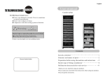
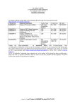
KWA-300 3D Installation and Parts Manual
LAUNCH
Spot Inspection Item Table before Installation ....... 20
Table of Contents
General Information..................................................... 1
Brief Installation Introduction..................................... 1
Precautions before Installation.................................. 1
Installation Tools........................................................ 1
Power Supply Requirement....................................... 1
Unpacking .................................................................... 2
Cabinet Box............................................................... 2
Post Box.................................................................... 2
Accessory Box........................................................... 4
Parts and Structures of Main Equipments错误!
未定
义书签。
Parts List of Main Equipments................................... 5
Structures of Main Parts.......错误!未定义书签。
Camera ................................................................. 6
Target.................................................................... 7
Wheel Clamp ........................................................ 8
Steering Wheel Holder.......................................... 9
Brake Pedal Holder............................................. 10
Overall Structure.........................................................11
Overall Structure ......................................................11
Main Unit ..................................................................11
Video Cameras and Posts........................................11
Video Cameras ....................................................11
Posts....................................................................11
Targets and Wheel Clamps ..................................... 12
Communication Cables ........................................... 12
Turntables ............................................................... 12
Steering Wheel Holder ............................................ 12
Brake Pedal Holder ................................................. 13
Installation and Adjustment...................................... 14
Main Unit Installation............................................... 14
Post Installation....................................................... 14
Checking and Adjusting According to Spot
Inspection Item Table before Installation............. 14
Confirmation of Installation Location................... 14
Post Holding........................................................ 15
Video Camera Bracket Installation...................... 15
Video Camera Installation................................... 15
Cable Wiring and Others..................................... 15
Main Unit Adjusting...............错误!未定义书签。
Calibration for Installation........................................ 15
Precautions and Solutions ....................................... 19
Common Problems and solutions in Installation ..... 19
Precautions ............................................................. 19
i
LAUNCH
KWA-300 3D Installation and Parts Manual
General Information
Installation Tools
General Information
Tools needed in 3D wheel aligner installation are:
l 5m tapeline, accuracy: 1mm;
l iron hammer, > 2kg;
l cable drilling tool, Φ8 and Φ18 drilling bits;
l monkey wrench, medium size, 20cm;
l wiring tube, 4m;
l lineation chalk;
l hexagon ring spanner, M3—M22;
l cross screw driver, medium size, 20cm and 10cm;
l installation sets (including calibration frame,
installation bolts, etc.);
l level meter, accuracy: 0.02 degree.
Special caution: All the operations in this manual
should be performed by the technical personnel
trained by Launch for KWA-300 3D wheel aligner!
Brief Installation Introduction
This installation manual is only suitable for the
installation of KWA-300 3D wheel aligner (post type)
manufactured by Launch, this type of wheel aligner
mainly includes two installation components: cabinet
and two posts. For easy use and measurement,
following four factors should be taken into consideration
during installation:
l Working height of lift when aligning;
l Horizontal distance from the center of the turntable
on the lift to the post;
l Installation height of camera;
l Distance between left and right camera.
l Only the qualified technician can operate the Wheel
Aligner.
l The operator must have knowledge of computer
application and basic theory of wheel alignment.
The post height of 3D wheel aligner is 2000mm, and the
working height of the lift is between 600~1200mm, which
can satisfies the use requirements. Correct installation is
very important to the alignment performance and the
types of the vehicle that can be aligned, please do read
this manual carefully.
Power Supply Requirement
3D wheel aligner is a precise computer system that
needs 220±10%v 50Hz power supply. Good earthing
helps to protect the equipments and persons. If power
supply cable needs to be lengthened, its load must not
be less than 6A 220V. So in order to protect electronic
products such as 3D wheel aligner, it is suggested to
use AC power supply voltage stabilizer.
Note:
Installation engineer must confirm that power
supply satisfies the requirements above-mentioned
before switching 3D wheel aligner on.
Precautions before Installation
Spot Inspection Item Table before Installation must be
provided by business personnel before installation. It is
convenient for installation engineer to learn beforehand
if the spot satisfies the use requirements of 3D wheel
aligner and then select suitable installation bracket.
Working flow:
l If there is no Spot Inspection Item Table before
Installation, please fill out another kind of the table.
l Every measurement must be marked correctly
(very important) and confirmed by technical service
personnel.
l Solve the problems met in the process of filling out
the table first and then perform the installation.
l During installation, please abide by the advices and
requirements of this manual strictly. Please contact
the technical support engineers for help if
necessary. To install 3D wheel aligner together with
lift, mark out the spot according to the Spot
Inspection Item Table before Installation, install and
adjust the lift first and then install 3D wheel aligner.
1
KWA-300 3D Installation and Parts Manual
LAUNCH
Unpacking
The transportation package of 3D wheel aligner consists
of three separated package boxes: quadrate post box,
square cabinet box and accessory box.
Cabinet Box
For unpacking of the cabinet box, please take Fig. 2.1
as reference. There are two turntables placed on the
bottom of the cabinet box, and the communication
cables and the main unit are inside the box.
Fig. 2.1
Post Box
Two posts and a set of calibration frame are packed in
one package box as shown in Fig. 2.2.
2
Unpacking
LAUNCH
KWA-300 3D Installation and Parts Manual
Unpacking
Post
立柱
Bracket
支架
Bracket Shaft
Tie Rod
支架轴
拉杆
Fig. 2.2
3
LAUNCH
KWA-300 3D Installation and Parts Manual
Unpacking
Accessory Box
Please see Fig. 2.3:
Fig. 2.3
The accessory box includes printer, housing, camera boxes, monitor, targets, wheel clamps, brake pedal holder and
steering wheel holder.
4
KWA-300 3D Installation and Parts Manual
LAUNCH
Parts List
Parts List and Main Component Structure
Parts List
No.
1
2
3
4
5
6
7
8
9
10
11
12
13
14
15
16
Part Name
KWA-300 3D wheel aligner user’s manual
KWA-300 3D wheel aligner installation and parts manual
KWA-300 illumination post assembly(left)
KWA-300 illumination post assembly(right)
KWA-300 target assembly
KWA-300 calibration frame assembly
KWA-300 cabinet assembly
Mouse(Acer),PS/2
Keyboard(windows101), Acer ultra thin PS/2 plug L<455mm ,
PHILIPS 17 inches flat panel monitor
EPSON color ink jet printer
KWA-300 3D wheel aligner main unit
Mechanical turntable
Brake panel holder
Steering wheel holder
Wheel clamp
5
Qty
1
1
1
1
4
1
1
1
1
1
1
2
1
1
4
KWA-300 3D Installation and Parts Manual
LAUNCH
Components Structures
Structures of Main Components
Camera
Fig. 3.1
Parts list of video camera:
No.
1
2
3
4
5
6
7
8
9
10
11
Part Name
Lens gland
Filter
Lens cushion
Lens sealing ring (big)
Lens sealing ring (small)
Socket pan head screw
Camera box
Video camera bracket
Cross round head screw
Video camera
Glass installation pedestal
Side cover
6
Quantity
1
1
2
1
1
2
1
1
4
1
1
1
KWA-300 3D Installation and Parts Manual
LAUNCH
Components Structures
Target
Fig. 3.2 Target
Parts List of target:
No.
1
2
3
4
5
6
7
Part Name
Front cover
Rear cover
Sealing ring
Transparent glass
PVC board
Sealing gasket
Target modes
7
Quantity
1
1
1
1
1
1
KWA-300 3D Installation and Parts Manual
LAUNCH
Components Structures
Wheel Clamp
Fig. 3.3 Wheel Clamp Structure
Parts list of wheel clamp:
No.
1
2
3
4
5
6
7
8
9
10
11
12
13
14
15
16
Part Name
Arm(right screw thread)
Right thread bar
King pin
Pin
Left thread bar
Arm(left screw thread)
Claw (A)
Bolt
Knob
Gasket
Gasket
Bolt M6 X 12
Guiding plate
Nut M20
Claw(B)
O-ring (rubber)
8
Quantity
1
1
1
1
1
1
4
1
1
4
4
4
1
1
4
4
KWA-300 3D Installation and Parts Manual
LAUNCH
Components Structures
Steering Wheel Holder
Fig. 3.4
Parts list of steering wheel holder:
No.
1
2
3
4
5
6
7
8
9
10
11
12
Part Name
Slide bar
Spring
Push plate
Open securing screw
Left support bar
Nut M8
Right support bar
Support block
Nut
Adjusting sleeve
Nut M8
Support seat
9
Quantity
1
1
1
2
1
1
1
1
1
1
1
1
KWA-300 3D Installation and Parts Manual
LAUNCH
Components Structures
Brake Pedal Holder
4
5
6
7
8
9
3
10
2
1
Fig. 3.5
Parts list of brake pedal holder:
No.
1
2
3
4
5
6
7
8
9
10
Part name
Slide bar
Spring
Push plate
Rubber handle
Support plate
Slotted pan head set screw
Knurled screw M6X25
Support block
Nut
Adjusting sleeve
10
Quantity
1
1
1
1
1
6
1
1
1
1
LAUNCH
KWA-300 3D Installation and Parts Manual
Components Structures
The fuse is connected to power supply socket. The
power supply switch is on the left side panel of cabinet.
Overall Structure
Overall Structure
The KWA-300 3D wheel aligner mainly consists of main
unit, video cameras (Fig. 4.3) and their posts (Fig. 2.2),
targets, wheel clamps, communication cables, turntables,
steering wheel holder and brake pedal holder as shown
in Fig. 4.1.
Fig. 4.2
Video Cameras and Posts
Video Cameras
There are four CCD video cameras included in
KWA-300 3D wheel aligner. They are used to capture
the images of four targets installed on wheels
respectively. These video cameras are held between two
post shells as shown in Fig.4.3. Users do not need to
perform the video cameras calibrations during the use of
3D wheel aligner because precise video cameras
calibrations have been done during the first installation.
Fig. 4.1 Overall Structure
1、 target; 2、main unit; 3、wheel clamp;
4、steering wheel holder; 5、brake pedal holder;
6、mechanical turntable; 7、wheel clamp tie belt;
Main Unit
The main unit, which is a control and operating platform,
consists of cabinet, computer, main unit interface, power
supply, etc. as shown in Fig. 4.2.
The computer assembly includes industry computer,
monitor, keyboard, mouse, printer, image acquisition,
power supply switchboard and so on. The monitor,
mouse and printer therein are placed on the upper desk
of the cabinet. The industry computer is set in the upper
compartment of the cabinet. The image acquisition and
power supply switchboard are installed inside the
industry computer. The keyboard is on the keyboard
drawer.
The power supply assembly includes power supply
leads, power supply socket, fuse and power supply
switch. The power supply socket is set below the cabinet.
Fig. 4.3
Posts
The two posts KWA-300 3D wheel aligner are used for
containing and fastening the CCD cameras and their
signal cables. The two posts are respectively mounted
on the ground by anchor bolts, and the position
relationship between the posts and the cabinet is shown
in Fig. 4.4..
Note: No matter during or after using, ensure to
prevent the posts from swaying, otherwise the
position of camera will be changed, influencing the
test result ).
11
KWA-300 3D Installation and Parts Manual
LAUNCH
Components Structures
Communication Cables
There are 4 signal cables and 2 power supply cables for
infrared light between the main unit and the cameras of
KWA-300 3D wheel aligner, which should be fixed on the
ground at first installation, and should be protected with
the bushing. Ensure to prevent the liquid from entering
the inside of the cable bushing or to avoid putting the
heavy on it, in order to prevent the bushing from being
damaged.
Turntables
Bridges
and
Transition
KWA-300 3D wheel aligner has two mechanical
turntables (standard configuration, see Fig. 4.6):
Fig. 4.4
Targets and Wheel Clamps
KWA-300 3D wheel aligner totally has 4 target-clamp
assemblies, which are key components for whole test
system, and are the objects monitored by cameras.
There are some bull-eye signs for installing the wheel on
the targets as shown in Fig. 4.5.
Fig 4.6
The turntables are placed at the front wheel positions
of the vehicle on the lift.
Use the lock pin to lock the turntable before driving the
vehicle on. Pull out the lock pin after the vehicle is
stopped and the front wheels are at the centers of the
turntables.
While testing, try your best to keep the vehicle front
wheels at the centers of the turntables.
Each turntable is equipped with a transition bridge,
which is placed between the turntable and lift, ensuring
the wheel on the turntable move reposefully.
Fig. 4.5
Whether the wheel clamps are fastened correctly or not
has the great relations with the test result. Turn the
adjusting knob to adjust the span between wheel claws
until it is proper, and then attach the clamp to the wheel
rim. Adjust the knob to make the wheel clamp fixed on
wheel rim tightly. Use the wheel clamp tie to bind the
wheel clamp and the wheel rim together.
Steering Wheel Holder
KWA-300 3D has a steering wheel holder as shown in
Fig.4.7. Use the steering wheel holder to lock the
steering wheel according to the tips on the screen.
The installation of wheel clamp is crucial to the test
result. The claws should be in even contact with the
wheel rim without touching the lead weight.
Avoid hitting during operation. Otherwise, distortion may
be caused and the test result may be influenced.
12
KWA-300 3D Installation and Parts Manual
LAUNCH
Fig. 4.7
Brake Pedal Holder
KWA-300 3D has a brake pedal holder shown in Fig. 4.8.
It is used to hold the vehicle brake pedal down to ensure
the vehicle will not move forward and backward during
testing procedure.
Fig. 4.8
13
Components Structures
LAUNCH
KWA-300 3D Installation and Parts Manual
Installation
Debugging
and
Installation and Debugging
E
F
C
D
B
2000~2500mm
Professional technical personnel are responsible for the
installation and calibration of KWA-300 3D wheel aligner.
Users need not to do these but to provide installation
conditions as follows: KWA-300 3D wheel aligner is a
type of three dimensions infrared image wheel aligner,
and it should be used indoors without strong infrared
light irradiating directly. So it is best to be installed
indoors.
2500mm
Central
Line
A
Turntable
Install the Main Unit
l Place the cabinet to a suitable place and leave
enough places for installation. Open the door on the
lower part of the cabinet, and undraw the drawer. And
you can see the User’s Manual, Parts Manual, Packing
List, etc. Please keep them well.
l Place the mouse on the top of the cabinet. Lead
the cable to the computer inside the upper compartment
of the cabinet through the hole on the back of the
cabinet.
l Unpack the packing box of the monitor, place the
related materials well and install the monitor. Lead the
cable to the computer through the hole on the back of
the cabinet. Plug the power plug into the connection
board on the lower compartment inside the cabinet.
l Unpack the packing box of printer, place the
related materials well and install the printer. Lead the
printer communication cable to the computer through the
hole on the back of the cabinet. Install the ink cartridge.
Plug the power plug of the printer power cable into the
connection board on the lower layer inside the cabinet.
l Lock the four doors of the cabinet at last. The
installation of main unit is complete.
Lift
Fig 5.1
l Confirm the lift height
For the lift with multi-level height, please select suitable
working height (from 0.6m to 1.2m) for operators to push
and pull vehicles conveniently, as well as adjust toe-in
and camber, etc. Mark at the corresponding shift
positions of the lift as the alignment height when users
operate on it each time. Measure the height between
ground and turntable center and fill it in the
corresponding column of Spot Inspection Item Table
before Installation.
l Confirm the post installation central line
Obtain two center points by measuring front and rear
widths between two lift runway rails. Connect these two
points to confirm the central line of the lift, lengthen the
line in the direction of posts.
l Confirm the post base line B
Confirm line B according to the positions of two
turntables. Make sure that this base line is parallel to
turntable central line and vertical to lift central line. The
distance between line B and the turntable central line is
2500mm.
l Confirm installation positions (C and D) of left and
right post (as shown in Fig.5.1, both point C and point D
are the points of line B, their symmetry center line is the
central line of the lift. The distance from C to D is
2000-2500mm).
l Place two posts on the ground vertically and make
the sides with wiring wholes below left and right post
face to face, drill on the ground by cable drilling tool
according to the installation holes on the post pedestals
Install the Posts
Checking and Adjusting According to Spot
Inspection Item Table before Installation
Confirm the Installation Position
The position relationship of posts and lift is shown in
Fig.5.1:
14
LAUNCH
KWA-300 3D Installation and Parts Manual
Installation and Debugging
and then install the anchor bolts. During installation
make sure that the posts are vertical to the ground and
their sides with LAUNCH labels are towards the lift.
Fix the Posts
1) Place the posts on the anchor bolts vertically;
2) Ring the bolts with plain washers, spring washers
in turn, and then screw the nuts on the bolts and tighten
them with wrench.
Line-in
hole
Line-in
hole
Install the Video Camera Bracket
Connect video camera to the top of the post by four
screws, then tighten them with wrench.
Install the Video Cameras
Fig 5.2
Install two video cameras respectively on the left and
right video camera bracket. Install left rear and left front
camera boxes on the upper and lower positions of the
left post video camera bracket. Thread the video camera
shaft through the hole of the video camera bracket and
tighten it by locking handle. In the same way, install right
rear and right front camera boxes on the upper and
lower positions of the right post video camera bracket.
Debugging of the Main Unit
l Debug the main unit before operating the wheel
aligner.
l Connect the main power cable to the power socket
(220V AC) , press down the indicator switch on the left in
the middle of the cabinet to power the main unit.
l Take out the key in the packing box of computer
and open the computer, press down the power supply
switch to start the computer. Enter the WINDOWS2000
operation system.
l Press down the power supply switch of the printer.
Print the test page to see if it is normal.
l The debugging of main unit is successful if all the
above steps are normal. Exit WINDOWS2000 and
shutdown the computer.
Cable Wiring and Others
1) Place monitor, printer, keyboard and mouse on the
proper positions of the cabinet and connect the
corresponding cables. Put the cabinet on suitable place
between left and right post.
2) Thread left front video camera cable and
illumination cable, as well as the left rear, respectively
through the left post and then use cable-locking clamp
on the top post to hold cables. Thread the other ends
through the wiring hole on the bottom of the cabinet and
connect them to the corresponding sockets on the
computer rear panel. Hold cables by cable-locking
clamps on the line-out position of the post and line-in
position of the cabinet. Connect and hold the cables of
the right post in the same way.
Calibration for Installation
Note: In normal using, please do not perform the
calibrating operations. The “left front, left rear, right
front, right rear” mentioned in this manual refers to
the orientation when the driver faces to the cameras.
15
LAUNCH
KWA-300 3D Installation and Parts Manual
Fig 5.3 Installation calibration sketch map
16
Installation and Debugging
LAUNCH
KWA-300 3D Installation and Parts Manual
Installation and Adjustment
sure all the support legs of the calibration bar are placed
steady and in the same surface. Finish the other calibration
bar installation in the same way.
1) Calibration Frame Assembling
Hold calibration support leg on calibration bar by M8
hexagon ring spanner. Attention: keep the support leg end
face close to calibration bar end face and tighten them.
When holding the other calibration support leg, please make
Holder Block
Calibration Shaft
Lock Screw
Adjusting Screw
Bracket
Fig 5.4
2) Calibration Frame Installation
Adjust alignment platform to common height that used for
vehicle alignment. Install calibration frame symmetrically on
alignment central line and make front wheel calibration bar
on turntable. In both sides of front and back calibration bar,
connect two isometric tie rods and make them close to the
end face of support legs. According to the signs on the
target, on both sides of calibration bar, install targets left
front, left back, right front and right back. Adjust the position
of calibration bar, measure the measurement terminals on
the top of support legs and make the difference between
two diagonals of calibration rectangle less than 1mm. Keep
level meter close to target surface and make the horizontal
bubble in the middle by adjusting target. At last, hold target
by turning the lock handle of target lightly and keep the
whole calibration instrument stand still. The installation
calibration sketch map is shown as Fig3.3.
Fig 5.5
4) Video Camera Holding
In the end use two M6*10 socket head screws to lock
horizontal adjustment. Tighten the lock handle and use two
M6*10 socket head screws to lock vertical adjustment.
Cover the post housing from the top, hold it by M4X6 round
head screw and seal with guarantee. Use M3*5 screw to
seal side board and seal with guarantee. Later pay attention
to prevent post and camera from strong bump to shift.
3) Video Camera Adjustment
Run 3D wheel aligner software and click pushbutton
[TARGET WATCH] in alignment testing surface. The screen
displays images observed by each camera. Adjust visual
angle, and make every target image in the center of every
visual field. Adjust focus distance to +∞, fine adjust aperture
and make gray level value in each visual field between
130~150. Hold the focus and aperture of lens by glue.
5) System Calibration:
Click pushbutton [SYSTEM CALIBRATION] in alignment
17
KWA-300 3D Installation and Parts Manual
LAUNCH
Installation and Adjustment
testing interface. When the screen reminds to input
password (provided by LAUNCH), then do it and press [OK].
Fig 5.8
Select left front target, press [TARGET CALIBRATION]
pushbutton, unscrew the lock handle lightly, and rotate the
left front target with even force to lean backward direction
according to the prompt of the icon. The screen displays the
angle that the target has rotated in real time. Reset the
target until the screen arrow reminds to rotate backwards,
stop and lock the target tightly when the angle is less than
0.1 degree.
Select left back target, press [TARGET CALIBRATION]
pushbutton, unscrew the lock handle lightly, and rotate the
left back target with even force to lean backward direction
according to the prompt of the icon. The screen displays the
angle that the target has rotated in real time. Reset the
target until the screen arrow reminds to rotate backwards,
stop and lock the target tightly when the angle is less than
0.1 degree.
Select right front target, press [TARGET CALIBRATION]
pushbutton, unscrew the lock handle lightly, and rotate the
right front target with even force to lean backward direction
according to the prompt of the icon. The screen displays the
angle that the target has rotated in real time. Reset the
target until the screen arrow reminds to rotate backwards,
stop and lock the target tightly when the angle is less than
0.1 degree.
Select right back target, press [TARGET CALIBRATION]
pushbutton, unscrew the lock handle lightly, and rotate the
right back target with even force to lean backward direction
according to the prompt of the icon. The screen displays the
angle that the target has rotated in real time. Reset the
target until the screen arrow reminds to rotate backwards,
stop and lock the target tightly when the angle is less than
0.1 degree.
Fig 5.6
a)
Camera Calibration:
Fig 5.7
Select left front camera, click [CAMERA CALIBRATION] to
calibrate it;
Select left back camera, click [CAMERA CALIBRATION] to
calibrate it;
Select right front camera, click [CAMERA CALIBRATION] to
calibrate it;
Select right back camera, click [CAMERA CALIBRATION] to
calibrate it;
b) Target Calibration:
18
LAUNCH
KWA-300 3D Installation and Parts Manual
Precautions and Solutions
Common Problems and solutions
in Installation
Can KWA-300 work with 110v working power supply?
Yes, it can. Set the switch on the back of the computer to
110v. Notice if the monitor and printer bought by user
satisfies the power.
How to do when run the software and display the
prompt of “Illegal user”?
At first examine if the watch dog is installed properly or in
poor contact. Then check if the serial number and user’s
password provided are correct. If necessary, contact with
technical service section of our company for verification.
How to do when run the software and display the
prompt of “Hardware does not exist”?
Run “Equipment Management” software in Win2000
program at first and check if there are two “domino alpha”
equipments included in Eurecard. Then examine if the
image acquisition card is loose. With the help of changing
the acquisition card’s position in PCI slot, judge it is the fault
of PCI or the acquisition card and replace it.
How to do when run the software and select “Target
Monitoring” but with no images display?
First check cables of video camera and illumination if the
connection is right and the illuminating lamp is lightened.
Secondly, check the light path. Sway target near the camera
lens and observe if there is image appears. At last check if
the camera aperture is “C” and if it is adjust the camera to
suitable position (according to the video camera adjusting
requirements in the chapter of calibration for installation).
Precautions
Calibration for installation is the base of 3D wheel
aligner, so every step of operations must be very careful.
Otherwise, test precision and equipments usage will be
affected.
Ø After calibration for installation, posts and cameras are
not permitted to move and adjust.
Ø Keep target clean;
Ø The filter on camera box is a special optical material,
so it must be kept clean and cleaned with soft lens tissue
when dirty. Avoid crushing the filter and moving the camera.
Ø
19
Precautions and Solutions
KWA-300 3D Installation and Parts Manual
LAUNCH
Appendix
Spot Inspection Item Table before Installation
Inspection Item
Installation Requirement
Height of aligning platform (vertical AH=600~1200mm
distance from ground to turntable
top )
Post standard distance (horizontal AB=2000~2540mm
distance from turntable center to
post installation base)
Distance between left and right CD=2000~2500mm
post
Height difference between front <2mm or 0.1degree
and back of aligning platform
Power supply Requirement
AC220 or 110v 5A
20
Actual Measurement
Assessment